1. Introduction
Cleanroom technology plays a crucial role in various industries, including semiconductor manufacturing, pharmaceutical production, biotechnology research, and aerospace engineering, where controlled environments are required for high-quality manufacturing. Stringent cleanliness requirements are necessary to prevent particles and other elemental or molecular contaminants from compromising sensitive processes or products. In specific cases, such as semiconductor or medical device manufacturing, vacuum is applied for a further improvement of process cleanliness and quality, or it is inevitably present, as in space applications [
1,
2]. A low volatility to prevent outgassing or evaporation is an initial requirement for all materials employed in a cleanroom environment.
Such conditions place special demands on tribology [
3,
4]. While the active surfaces of tribologically stressed components normally have the opportunity to form friction- and wear-reducing surface layers through chemical reactions with the gaseous ambient medium under atmospheric conditions, this is not possible in vacuum, where adhesion mechanisms dominate in the contact interfaces and can lead to malfunctions and the failure of tribological systems [
5]. It is furthermore well known that in particular, solid lubricants, which are often parts of grease formulations, lose their lubricating functionality without the presence of oxygen or water. Finally, additives or low-boiling oil fractions can evaporate from lubricant oils, which can result in changes in properties such as chemical stability of viscosity. Therefore, general testing techniques and technologies have been developed to address the area of vacuum tribology [
6,
7,
8].
The market for high-performance lubricants in the space, vacuum technology, cleanroom and semiconductor industries requires highly specified and well-understood materials, in particular due to the high cleanliness standards and the demand for long maintenance intervals, as the components are either difficult to access (space), or maintenance would lead to machine downtime and thus to high costs due to production losses (especially in the semiconductor industry). On the other hand, the demand for very small quantities in comparison with other industries is very characteristic. This niche is unattractive for major lubricant manufacturers that are used to supplying material multiple tons instead of grams to kilograms. As a result, the range of lubricant options is very limited, and users often have no choice but to use a commercially available standard product, to quantify the risk of failure at great expense and to plan and implement appropriate measures.
Two types of commercially available technical products dominate the field of clean and vacuum-compatible high-performance lubricants, perfluoropolyethers (PFPE) and multiple alkylated cyclopentanes (MAC). PFPE have a wide range of operating temperatures, but are virtually incompatible with additives due to the fluorinated base oils, i.e., only limited options for formulations with property-enhancing ingredients exist. In addition, they tend to degrade autocatalytically on ferrous surfaces, which drastically reduces the service life of tribological systems [
9,
10]. MAC lubricants, on the other hand, are known for long lifetimes, but are limited in the range of application temperatures due to their less inert chemical structure. Stability can be improved by the use of additives, which can, however, significantly enhance outgassing. In addition, this product group often exhibits high starting friction, which is problematic for the safe design of the drive technology [
11]. There is also a risk that the MAC oils generate hydrogen through tribochemical reactions, which can lead to premature rolling bearing failures [
12,
13].
Ionic liquids (ILs) are organic salts; they consist of cations and anions that are (partially) built up from hydrocarbon structures and that are often liquid at room temperature and below. ILs display several advantages that make them suitable as promising compounds for clean and vacuum-compatible high-performance lubricants, in particular vacuum lubricants, such as a negligible vapor pressure, a high thermal and chemical stability, and a low flammability. Their advantageous tribological properties have been reported in various scientific studies [
14,
15,
16,
17] and in the context of vacuum lubrication for space application [
11,
18,
19,
20]. Commercial interest in ILs as lubricants has been mainly limited to their use as functional additives, for example, to improve conductivity in conventional lubricants to reduce the risk of electrocorrosion. This can mainly be related to the high cost in comparison to conventional mineral oil-based lubricants. ILs used as lubricant base oils display a promising alternative to the commercially available clean vacuum lubricants due to their potential to combine the thermal and chemical stability of PFPE-based lubricants with the lifetime of MAC fluids. While the potential is evident, and a high demand for such specialty lubricants exists, the development of IL-based lubricants represents a high financial risk. Due to the extreme consequences of failure of tribological systems, a very complex risk management is carried out that involves extensive and cost-intensive test campaigns [
6]. Hence, and in particular for very new and innovative technologies, potential customers have to be convinced by good technical and scientifically sound arguments to consider the use of new products. In the tribological test chain, there is a large gap between initial model tests like the spiral orbit tribometer (SOT) [
6,
7,
8] and dedicated component testing. The transferability of the results from the highly simplified tests to the behavior of original components such as roller bearings, plain bearings, linear guides, or spindle drives is not given [
21]. This leads to major problems in the design of these construction elements and the selection of suitable material and lubricant combinations.
There is therefore an urgent need to develop an application-oriented test methodology for carrying out component or aggregate tests to evaluate the new high-performance lubricants under cleanroom and vacuum conditions. Such a multi-stage test methodology does not yet exist. Due to the storage and assembly of the components in an earth atmosphere, the tests must be carried out under both cleanroom and vacuum conditions. In addition, quick, simple tests, as well as more complex and application-related component and component tests, must be carried out as part of tribological testing.
This paper describes the systematic investigation of five ILs for use as base oils for cleanroom and vacuum lubricants, and in particular the development of a new type of component test rig and its integration into the material characterization process. In this rig, high-performance lubricants can be tested under cleanroom and vacuum conditions by replacing modular linear slideways, plain, and roller bearings as well as ball-screw drives in close proximity to the application. Initial measurement results show that the new test stand fulfills the expectations placed in it.
2. State of Research
2.1. Scientific Fundamentals of Ionic Liquids
Among the numerous publications about ionic liquids, many research papers and reviews discuss the applicability of ionic liquids as lubricants [
16,
22,
23,
24,
25]. While the beneficial lubrication properties of pure ILs are commonly highlighted, their high cost and a potential corrosion risk are typical arguments for use as lubricant additives instead [
16,
17,
26]. Indeed, most conventional applications could benefit from IL additives, but not fully exploit the potential that their specific properties offer. However, the following unique combination of features makes them very promising compounds for use in cleanroom (vacuum) high performance applications:
2.1.1. Vapor Pressure
Outgassing and evaporation are of particular concern for lubricants employed in cleanroom or vacuum applications. Firstly, volatile organic species mean a contamination risk for a clean environment, which can be particularly critical when sensitive (e.g., optical) equipment is present. In vacuum, evaporation of volatile compounds increases significantly, which can lead to vaporization either of low molecular mass fractions of an oil or functional additives—both mean a risk for the functionality of the lubricant. Ionic liquids are known for their very low vapor pressures, even at elevated temperatures [
27,
28,
29]. It is challenging to determine reliable vapor pressures, since many ILs begin to decompose before their vapor pressure is measurable [
27].
2.1.2. Thermal and Thermo-Oxidative Stability
The stability of ILs depends on the type of cations and anions, but also on their interaction. In particular, cations based on heterocyclic aromatic structures such as pyridinium, pyrrolidinium, or imidazolium are known for a high bond strength and overall stability. Less-stable cations are ammonium or phosphonium based aliphatic structures. For many ILs, the choice of anion is more critical than the choice of cation with regard to the thermal stability. In a recent study, the thermal stability of 66 ILs was compared by thermogravimetric measurements [
30]; the most stable compounds from this study contained the fluorine-containing anions bis(trifluoromethyl)sulfonylimide, tetrafluoroborate, or hexafluorophosphate with onset temperatures higher than 400 °C. A relatively high decomposition temperature can, however, provide a wrong perception of the long-term stability. Fox et al. published a long-term study where the stability of ILs over 16 weeks of oven storage at elevated temperatures was examined [
31]. During that period, the physical appearance and material properties of many tested substances changed drastically. It was shown that, in particular, the imidazolium ILs were most resistant to degradation, which is in line with the findings from other studies [
32].
2.1.3. Tribological Properties
The potential of ILs for tribological use has been widely researched, with the ILs being used both as a base fluid and as additives [
14,
15,
16,
17]. It has been shown that ILs lubricating metallic contacts can tribologically outperform commercially available fully formulated oils. The ability to react with metal surfaces under formation of a tribofilm can significantly reduce friction and wear. However, the knowledge in this field is still quite undeveloped, and it has been noted as recently as 2013 [
33] that there is still no clear understanding of the mechanism for lubrication, and selection of ionic liquids for tribological applications tends to be based on trial and error.
The use of ILs for tribological vacuum applications has been discussed in the context of the space industry [
20,
34,
35,
36]. While different cation types were discussed, it was an outcome of several studies that ILs that contained the bis(trifluoromethyl)sulfonylimide (BTA) anion showed the most advantageous properties.
2.2. Available Test Rigs
According to the current state of the art, only model test rigs are commercially available for testing tribological properties under vacuum conditions. This means that the tribological system consists of simply abstracted test specimens, such as balls, disks, or plates.
In the aerospace sector, tests on the so-called spiral orbit tribometer (SOT) are standard in the qualification phase of lubricants and coatings [
37,
38]. The spiral orbit tribometer (SOT) is a thrust bearing with only one ball and flat raceways [
8]. As in an original rolling bearing, the ball is subject to rolling, spinning, and sliding motion. This is a much more realistic bearing simulation than other tribometers that only perform unidirectional sliding.
Figure 1 shows the instrument’s internal components in detail. A single ball is loaded between two flat plates. As the lower plate rotates, the ball is driven in a nearly circular orbit. The orbit is actually an opening spiral, with the spiral’s pitch directly related to the friction coefficient. At the end of each orbit, the ball contacts the guide plate, which returns the ball to its original orbit radius. This orbit is repeatable during the entire test. A sensor measures the force exerted by the ball on the guide plate and this yields the friction coefficient. The instrument’s kinematics are well understood [
37].
For most of the orbit, the ball undergoes pure rolling with spin; however, when the ball comes into contact with the guide plate, there is a certain mechanical impact with increased sliding ratio. This region is colloquially termed by the inventors of the test bench the ‘scrub’, and the majority of lubricant degradation occurs here. An important assessment parameter in this test is lubricant degradation, which can be measured online using a gas element analyzer. Additionally, the SOT determines the friction coefficient of both the lubricated system and the non-lubricated specimens. The relative lifetimes of lubricant/material combinations correlate with full-scale ball bearing tests, and can be used to select the appropriate lubricant for an application.
In the SOT, Hertzian contact stresses between 0.50 and 5.00 GPa can be set using different normal forces and ball sizes, which corresponds to typical rolling bearing applications. Standard test plates are manufactured from 440C steel and polished to a surface roughness Ra < 0.05 microns. Typical balls used are either 12.7 mm (1/2″) or 7.14 mm (9/32″) diameter, manufactured from 400C and 52100 steel, respectively, depending upon the contact stress requirements of the particular test [
37]. The instrument is designed to operate in ultrahigh vacuum or with a cover gas. Test acceleration is achieved by limiting the lubricant amount on the ball to tens of micrograms.
In addition to the SOT test, lubricants are often tested in a ball/plate contact arrangement under oscillating sliding friction. However, as described above, this rarely corresponds to the real loading in the application. The test is therefore even more abstract than the SOT. Typical tribometers for this model test arrangement are the high-frequency, linear-oscillation (SRV) Test Machine in accordance with DIN 51834 or ASTM D7421 from Optimol Instruments [
19,
39,
40,
41] or a classical pin- or ball-on-disk test rig [
21,
38].
3. Assessment of Imidazolium-Based ILs as High-Performance Lubricants
While the excellent lubrication properties of ILs have been demonstrated, it is also known that they can exert significant corrosion on metallic surfaces, in particular in the presence of water [
42,
43,
44]. Making the molecular structure of an IL more hydrophobic could reduce water absorption and thus might reduce the corrosive impact on metals and alloys. This could, however, also impact other key properties for a lubricant, such as thermal properties, viscosity, or tribological functionality. In this investigation, five ILs that are based on an imidazolium cation and an fluoroalkyl sulfonylimide anion, but with differences in the length of the pendant alkyl groups of the imidazolium ion and the chain length of the fluoroalkyl group of the anion, were tested and compared (
Figure 2):
1-Butyl-3-Methylimidazolium Bis(trifluoromethylsulfonylimide) (BMIM BTA),
1-Octyl-3-Methylimidazolium Bis(trifluoromethylsulfonylimide) (OMIM BTA),
1-Butyl-3-Methylimidazolium Bis(pentafluoroethylsulfonylimide) (BMIM BETA),
1-Butyl-3-Methylimidazolium Bis(nonafluorobutylsulfonylimide) (BMIM BBTA) and
1-Octyl-3-Methylimidazolium Bis(trifluoromethylsulfonylimide) (OMIM BBTA)
3.1. Water Uptake
The water absorption from air is an indicator for hydrophobicity and is thus critical for the corrosion of metallic materials. Also, highly hydrophilic ILs that absorb significant amounts of water show an outgassing risk and do not fulfill cleanliness requirements for vacuum applications. For space application, a water content <1 wt % is required [
45]. It was expected that an increase in hydrocarbon group length at the imidazolium cation and an increase in fluorocarbon group length at the anion increase the hydrophobicity and reduce water absorption.
The candidate ILs were firstly dried by a bakeout in a glass flask in vacuum (100 °C, 10
−1 mbar, 24 h). Then, 1 g of each fluid was allowed to stand open in laboratory air (22 °C, 50% relative humidity), and the weight was monitored over several days until a constant level was achieved. Results are depicted in
Table 1.
The water uptake was low for all tested ILs, and a tendency towards lower water absorption could be observed. With regard to the chemical structure, it was expected that BMIM BTA behaves least hydrophobic, and OMIM BBTA the most, which is reflected in the experimental findings.
3.2. Thermal Properties
The properties at high and low temperatures were analyzed with different methods. Melting points were characterized rheologically with an Anton Paar MCR 702 rheometer. The following test conditions were applied:
- ○
Plate/plate measurement system.
- ○
Test plate size: 25 mm diameter.
- ○
Measurement gap/lubricant layer thickness: 1 mm.
- ○
Test temperature range: −20–25 °C at 1 °C/min.
- ○
Shear stress: 2 Pa.
The melting point was determined as the temperature at which a measurable rotation of the upper plate was detected. The thermal degradation was investigated with a NETZSCH Libra F1 thermo-microbalance (TGA). Samples were heated in air atmosphere from 20–700 °C at a rate of 10 °C/min; the thermal degradation was assessed as the temperature at which 2% of the original weight were lost. In addition, the long-term stability at constant temperature was analyzed. Therefore, 1 g of each fluid was stored in an oven for several weeks, and the mass loss was observed. Results are depicted in
Table 2.
Longer hydrocarbon groups in the cation and longer fluorocarbon groups in the anion increase the melting temperature due to their known tendency to crystallize. Also, and as expected, a higher susceptibility towards thermal degradation was observed with an increase in alkyl chain length. It can be seen that the range of operating temperatures would be smaller for these (more hydrophobic) ILs.
3.3. Viscosity
Viscosities and viscosity indices were determined rheologically with an Anton Paar MCR 702 rheometer. Tests at different shear rates and temperatures were performed in alignment with DIN 51810-1 [
46]; the viscosity index was calculated according to ASTM D2270-10 [
47]. The following test conditions were applied:
- ○
Plate/plate measurement system.
- ○
Test plate size: 25 mm diameter.
- ○
Measurement gap/lubricant layer thickness: 1 mm.
- ○
Test temperature range: 20–100 °C.
- ○
10 min holding time at target temperature before measurement.
- ○
Shear rate: 0/s–100/s.
Again, a behavior as expected from the chemical structures could be observed. The viscosity and the viscosity index correlate with the melting points and the hydrophobicity of the ILs.
3.4. Corrosion
Corrosion tests were carried out with SAE 52100 steel (1.3505, 100Cr6), as this is the standard material for rolling bearing parts; it is used in numerous tribological standard tests (such as SOT or SRV) and is also known to be very susceptible to corrosion. Therefore, round samples (height: 5 mm, diameter: 30 mm, surface roughness Rz: 6.3 µm) were manufactured. Samples were cleaned with acetone; afterwards, the surface was fully covered with IL. Samples were stored in a Memmert HCP 50 climate chamber for 2 weeks at 80 °C temperature and 60% relative humidity. The samples were compared visually. These tests only allowed a rough assessment (see
Table 4), since visual characterization is very objective and test results showed variation.
Test results indicate a correlation between corrosion and water absorption. While BMIM BTA had a severe corrosive impact on the steel, OMIM BBTA, in particular, showed only small signs of corrosive attack. An improved method would be required for a more detailed assessment.
3.5. Tribological Evaluation on Model Test Rigs
Parallel to the development of the new vacuum test bench, the first tests with the newly developed ionic liquids were already carried out under normal atmospheric conditions. Classic model tests on the SRV test bench [
39] and the mini-traction-machine (MTM) [
21] were used for this purpose.
First, the base fluid candidates without their thickener will be examined using an oscillating friction wear tribometer (SRV). Typically, lubricants are tested on the SRV under oscillating sliding friction, high pressure, high frequency, and small stroke in a ball/plate arrangement. The loads in the SRV represent a worst-case scenario, which probably only rarely occurs in real applications, but are regarded as a fast and consistent basis for comparing lubricants, which are also internationally recognized and standardized.
3.5.1. SRV-Test According to DIN 51834-2 [40] and ASTM D7421-1 [41]
In order to examine lubricants comparatively under model conditions in the laboratory, tests are often carried out today on the SRV oscillating friction wear test rig [
21]. In the simplest test, a 10 mm steel ball (100Cr6, hardened and polished) oscillates on a steel disk (100Cr6, hardened, lapped). This test places high demands on the lubricant to be tested, as mixed friction conditions constantly prevail due to the load collective and the oscillation movement, and the pressures are high due to the point contact.
In the SRV, the ILs provided by the project partner are used to carry out endurance runs in accordance with DIN 51834-2 (300 N load, 50 Hz vibration frequency, 1 mm stroke, 50 °C sample temperature, 2 h running time) [
40] to determine the friction and wear properties, as well as load increase runs in accordance with ASTM-D7421-1 [
41] (80 °C sample temperature) to determine the maximum load-bearing capacity. A double determination is used as the test statistic. The SRV is particularly suitable for testing these base fluids, as only a very small amount of lubricant is required for the individual test.
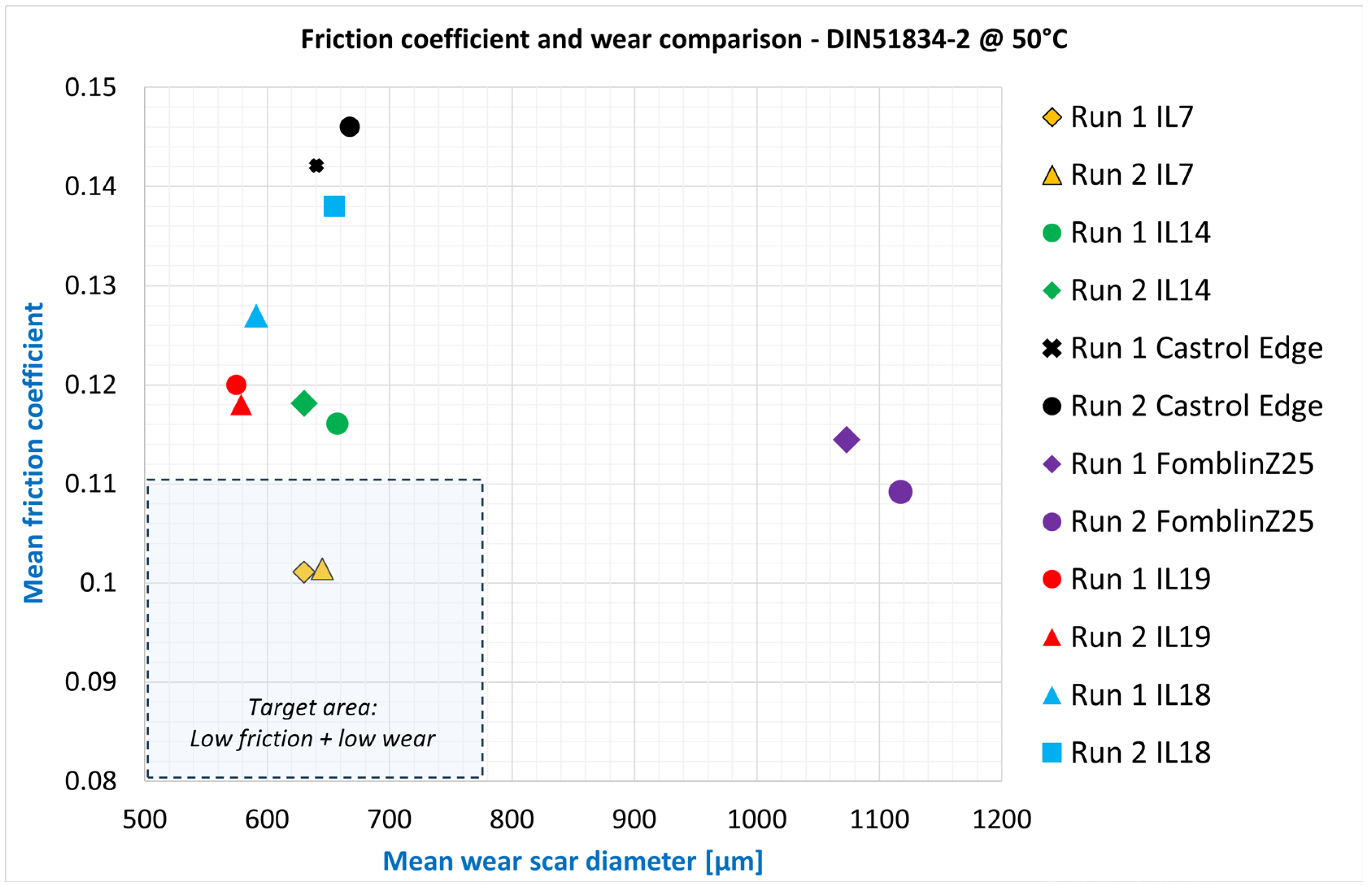
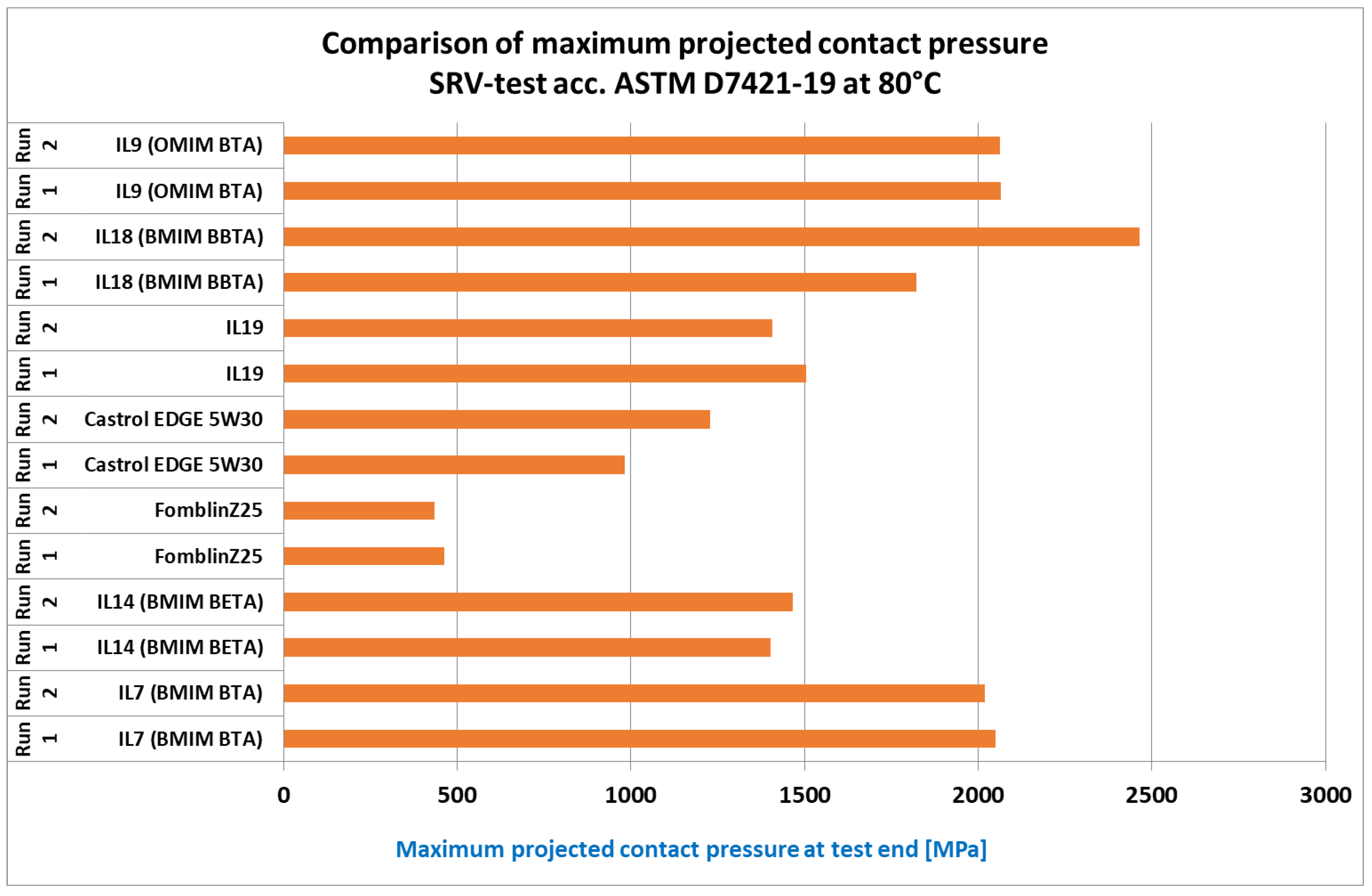
In addition to the ILs, two vacuum lubricants (a perfluoropolyether (PFPE—Fomblin Z25), a multiply alkylated cyclopentane (MAC)—Nye2001A) and a commercially available engine oil (Castrol Edge 5W30) are tested as comparative references. Ideally, the ILs are able to beat all references in the standard test. The results of these tests are shown in the following diagrams (
Figure 3 and
Figure 4).
Figure 3 shows the results from the DIN standard runs. An ideal lubricant shows a low friction level in combination with low wear (small calotte diameter) and is therefore located in the lower left area of the graph. It can already be seen here that the IL candidates examined are close to each other and can undercut both the commercially available engine oil in terms of friction and the PFPE in terms of wear. BMIM BTA, in particular, shows great potential here. The second vacuum lubricant, Nye2001A, was not able to pass this test at all, which is why it was not included in the graph.
In the ASTM load step run (
Figure 4), which particularly examines the high-pressure load-bearing capacity and protection against severe adhesive wear, similar results are shown. Here, even the weaker IL variants (e.g., OMIM BBTA, IL19) are on a par with the engine oil and shows a maximum surface pressure at least twice as high as the PFPE oil (the MAC also failed directly here again). The best IL variants exhibit maximum surface pressures of 2000 MPa (BMIM BTA, IL7)–2500 MPa (BMIM BBTA, IL18), which is equivalent to a high-quality gear oil in terms of load-bearing capacity. Due to its corrosion and temperature resistance, the project partner particularly favors variants of the BMIM BTA (IL7) sample for further development.
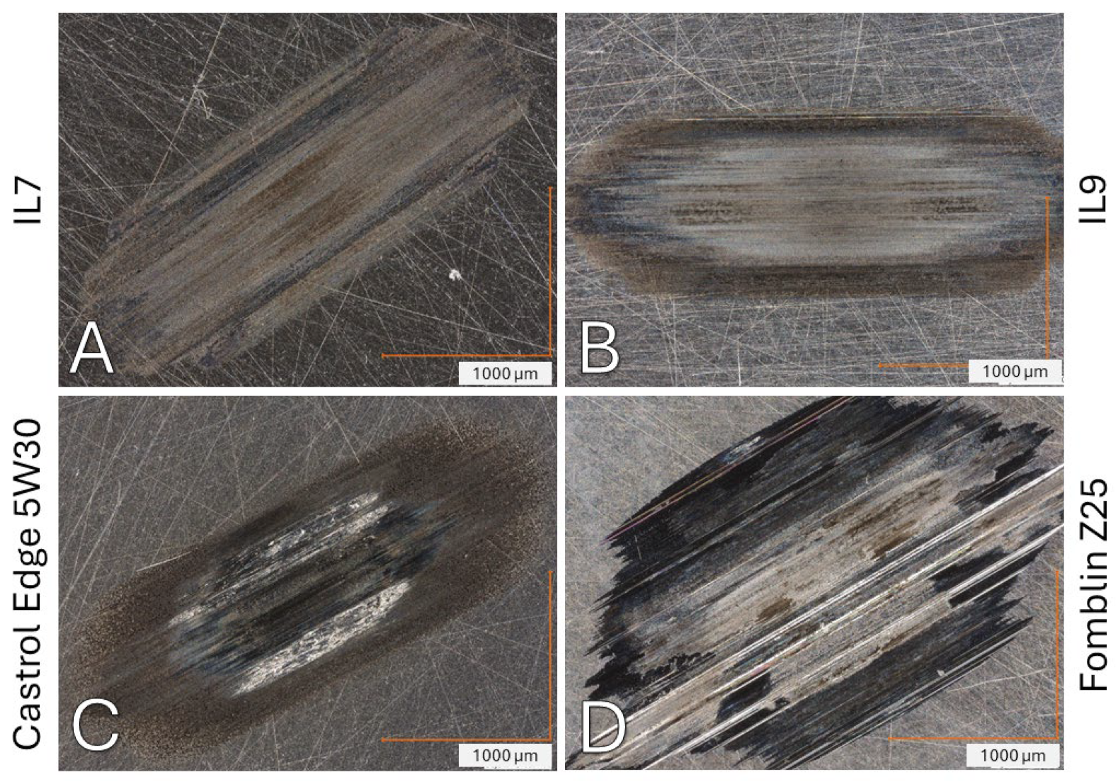
The good test values can also be seen in the microscopic images of the test specimens after the load increase run (see
Figure 5). While the engine oil and PFPE show pronounced signs of adhesive wear on the test specimens, the wear pattern of BMIM BTA and OMIM BTA is primarily characterized by a rather soft tribofilm.
For the further course of the project, repetitions of the SRV tests of the most promising IL variants with stainless steel test specimens (material 1.4125) and under a nitrogen atmosphere are planned. Both represent an approximation of the conditions present in the real system. The nitrogen atmosphere prevents reactions with the ambient oxygen, and stainless steels are often used in vacuum systems for corrosion protection purposes.
3.5.2. MTM-Tests
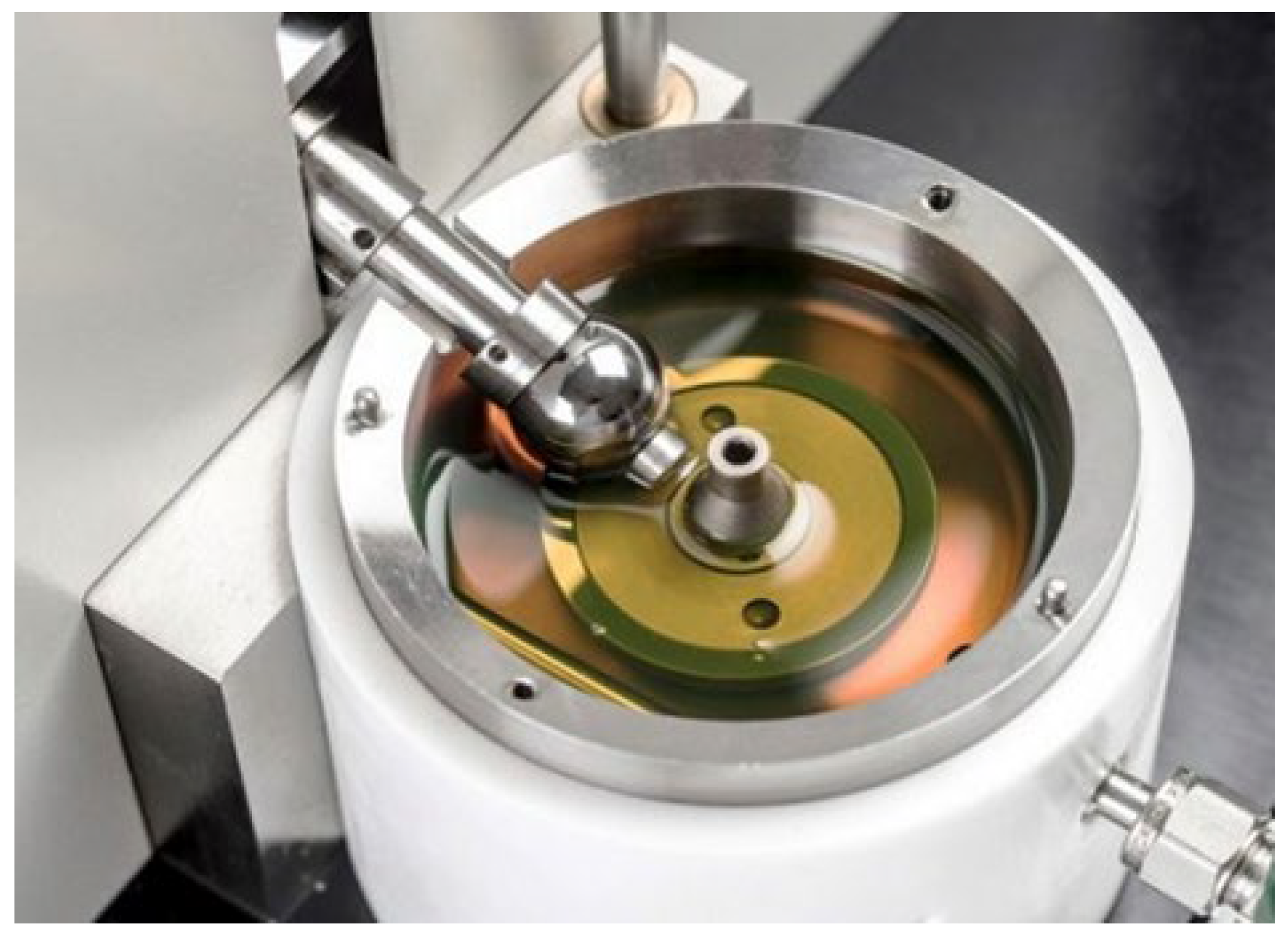
As soon as grease variants of the most promising ILs are available, these will also be tested under rolling load using a mini-traction machine (MTM, see
Figure 6). As described, many motion systems are designed as rolling systems under vacuum conditions, as the lowest possible friction and thus minimized heat input into the system can be achieved. In addition to the wear mechanisms of abrasion, adhesion, and tribo-oxidation present in the SRV tests, rolling friction also causes surface fatigue/breakdown. The plan here is to load the lubricating medium with repeated Stribeck and traction curves under 1 GPa Hertzian pressure until damage to the surfaces becomes noticeable due to increasing friction levels. The MTM tests are also to be seen as a preliminary stage or complementary to the rolling friction tests in the vacuum tribometer.
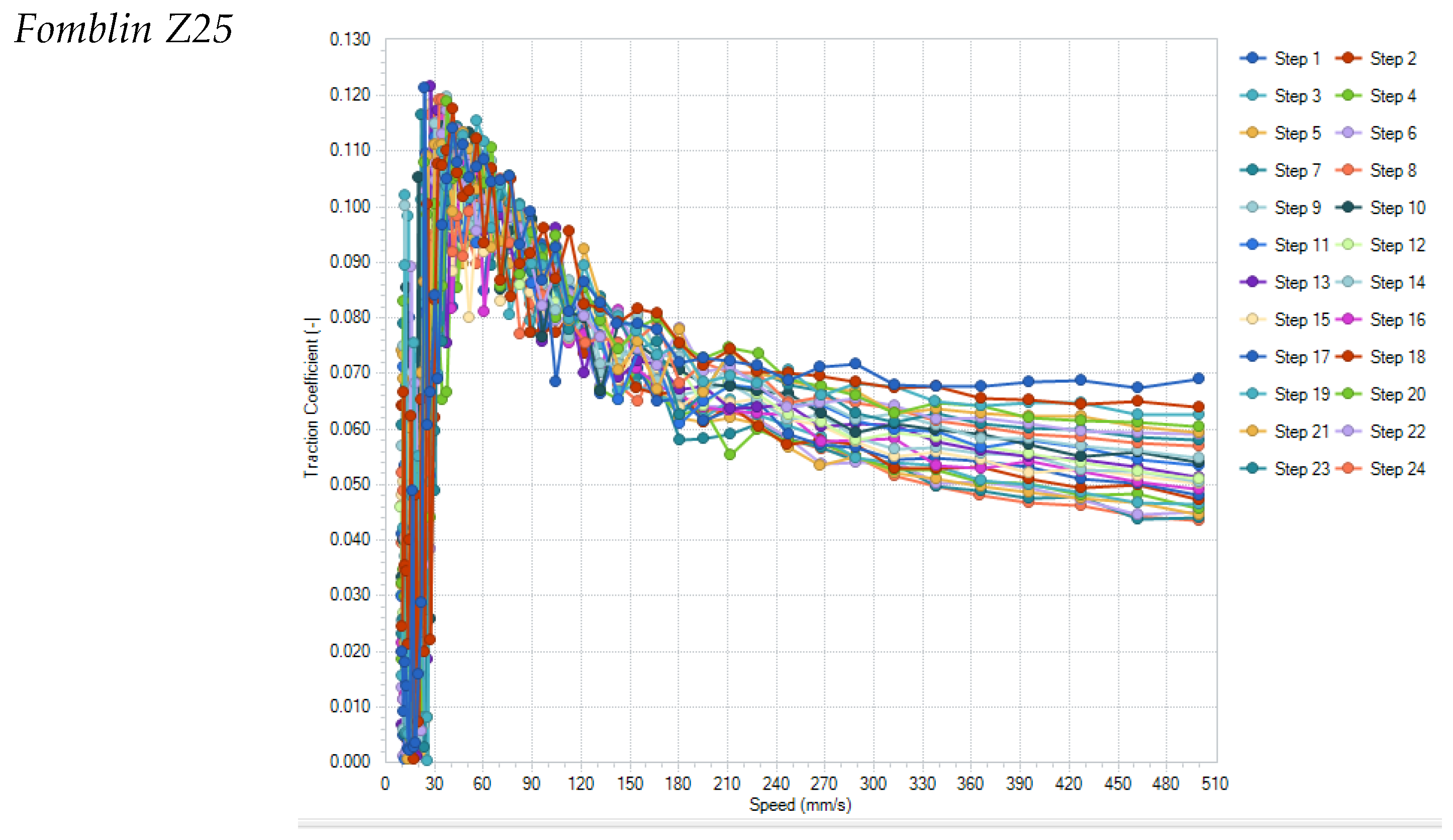
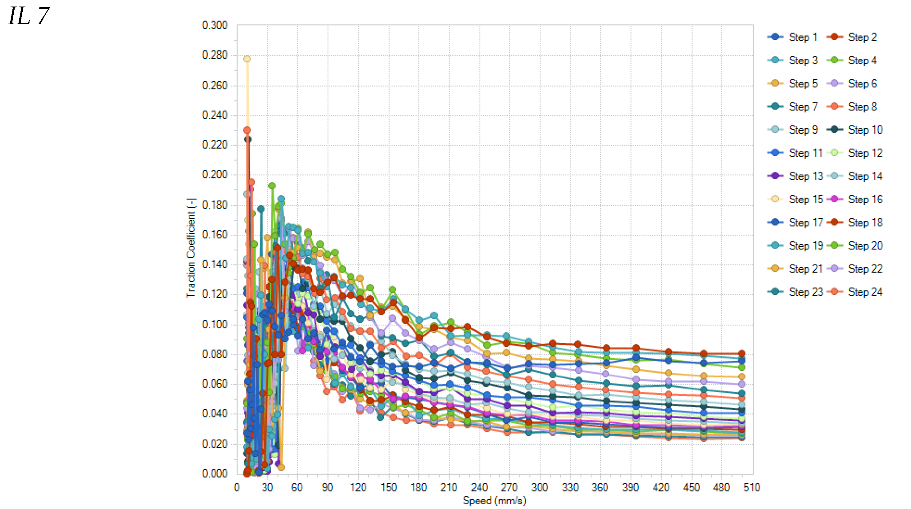
Preliminary tests of the most promising base lubricants—as used in the SRV tests—showed good results. Tests were conducted with repeated speed variation runs (so-called Stribeck tests) with 500–20 mm/s rolling speed, 1 GPa Hertzian stress, 2% Slide-Roll-Ratio, and 50 °C pot/ambient temperature. The lubricants were applied as initial lubrication of 0.25 mL on top of the AISI SAE 52100 ball-and-disc specimen.
Figure 7 shows the results of all individual runs for the samples Fomblin Z25 and IL7.
All tested lubricants were able to survive the 24 repetitions of the Stribeck curves. Noticeable is the significant change in the Stribeck curve of IL7 with increasing number of repetitions, which decrease to levels below 0.040–0.015 for speeds higher than 150 mm/s (0.07 for Fomblin), which is probably due to changes in the surface structure of the ball/disc-pairing surfaces (see
Figure 8). These show almost no smoothing wear for Fomblin but significant smoothing of the surface roughness for IL7, allowing a thinner specific lubrication film thickness and reduced friction.
3.6. Summary of Ionic Liquid Assessment
The characterization of differently modified imidazolium fluoroalkylsulfonylimide ILs revealed the impact of chemical structure on different properties that are relevant for lubricant application. It could be shown that longer hydrocarbon groups at the imidazolium cation and longer fluorocarbon groups at the sulfonylimide anion led to less water absorption and thus less corrosion on 52100 steel. On the other hand, earlier degradation as well as higher melting temperatures and viscosities resulted. The least hydrophobic compound BMIM BTA showed the best behavior during tribological characterization under ambient conditions (
Figure 9).
4. Development of a Test Methodology for the Tribological Characterization of Ionic Liquids in Vacuum and Cleanroom Applications
The aim of the project was to develop a completely new type of component test rig that closes the gap between simple category VI model tests and component or aggregate tests (category III) [
48]. For this purpose, the lubricants are tested in an interchangeable test cassette containing various design elements (
Figure 10). Specifically, these are linear plain guides, linear roller guides, plain and roller bearings, and ball-screw drives. All components are placed in an easily replaceable cassette and subjected to frictional loads against each other. This test rig is an essential component of the application-oriented test strategy for new lubricants based on ionic liquids for cleanroom and vacuum applications, which is also to be developed.
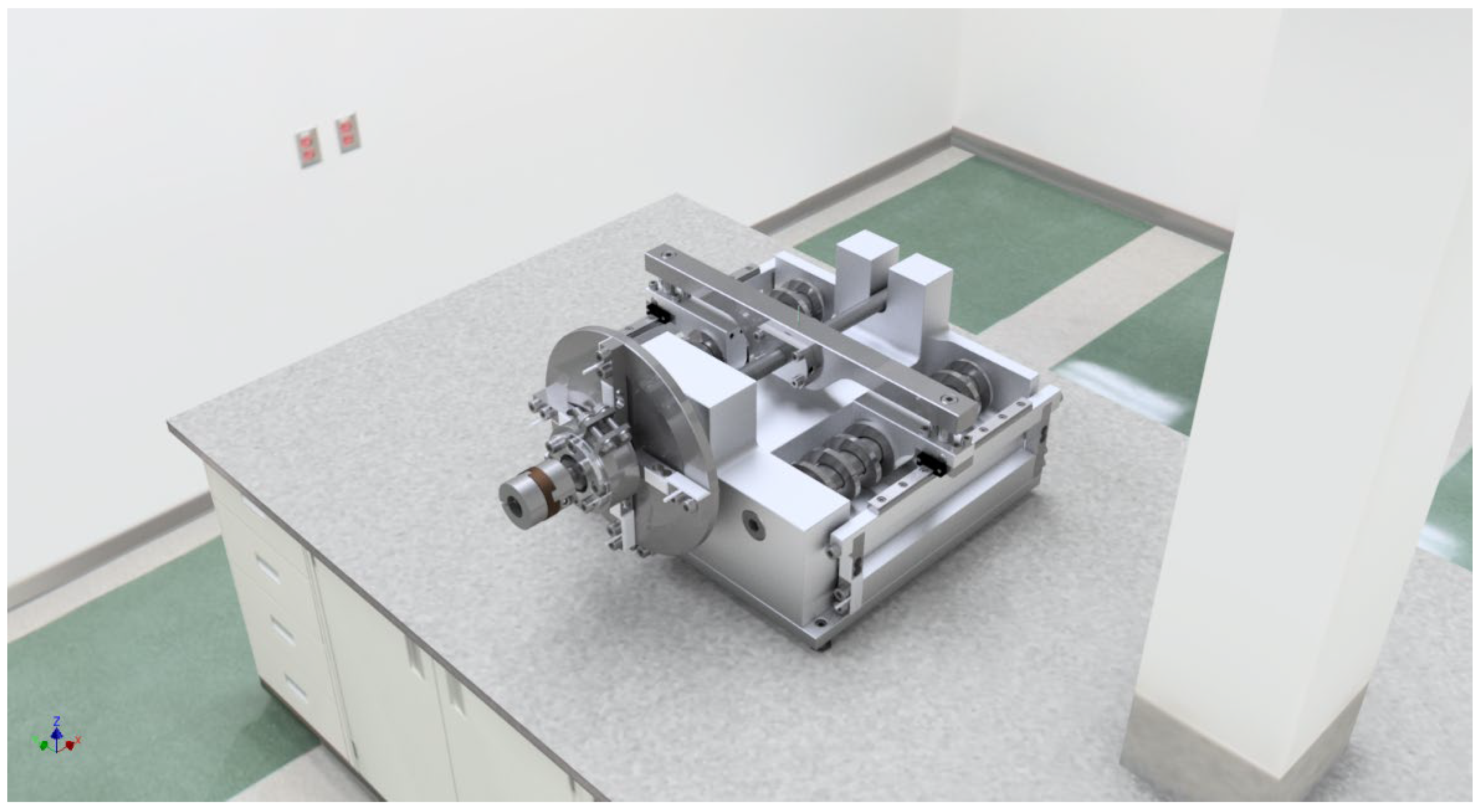
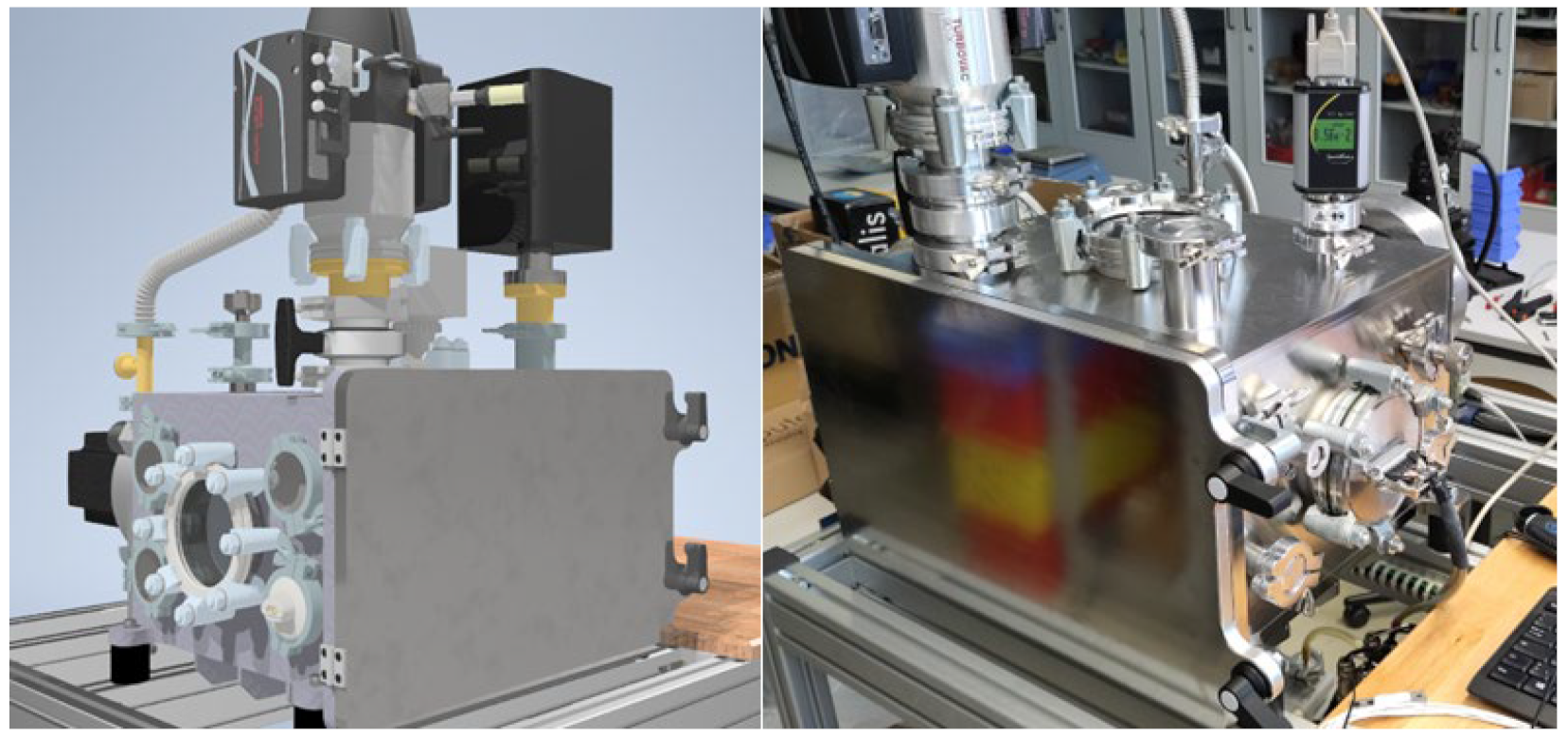
The novelty of the planned test concept is that with just one powerful servo motor as the universal main drive (attached to the chamber by a magnetic coupling), the new ionic lubricants can be tested, analyzed, and evaluated simultaneously in a vacuum in the four tribological systems. The magnetic rotary coupling makes it possible to get rid of traditional mechanical rotary feedthroughs with higher leakage rates, outgassing sealing fluids, short service lives or low maximum speeds. If only individual systems are to be evaluated, the other systems required for the force flow must be replaced by sufficiently powerful reference systems (oversized, coated elements). The particularly compact design of the test bench (
Figure 11) results from the conflicting technical requirements of testing as close as possible to the application (many different tribological systems) and, at the same time, efficiently in a high vacuum (10
−3 to 10
−6 bar), with the shortest possible evacuation times.
The solution for determining the adhesion, sliding, and rolling friction properties (efficiency, aging condition, etc.) of different lubricant/friction bearing/material combinations in the new test bench setup (in a vacuum) consists of the defined application of force and the measurement of the reaction force and temperature development using temperature sensors (IR and/or thermocouple). The recording of the tribologically important parameters for force, speed, and temperature is carried out using the measurement techniques described below, on the basis of which the high-precision measurement and mathematical analyses of the tribological systems are made possible. In this way, the main measured variable—friction—can be analyzed and evaluated with high precision by measuring the frictional force and additionally via the temperature change. This enables a direct plausibility check of this important variable.
The force application and measurement of the reaction forces should be carried out as follows:
- ○
Plain and roller bearings: Bracing of the bearing seats with a defined force to create a a contact pressure of up to 1.5 GPa or by introducing a radial force through the ball screw. The reaction force on the bearing housing is measured using strain gauge sensors.
- ○
Linear guide: Tensioning of the linear guide with a defined force to create a contact pressure of up to 1.5 GPa or by tilting the bushing. The reaction force on the guide shaft is measured using strain gauge sensors.
- ○
Spindle drive (threaded nut/ball screw): Tensioning of the spindle nuts or ball screw with a defined force (FL). The reaction force is determined by the increase in torque on the drive motor. This is determined via a reaction force measurement on the motor.
Measuring the friction of the individual systems separately in a vacuum was a considerable design and metrological challenge. For this purpose, only the friction behavior of the spindle system is measured via the motor torque. For all other systems to be tested, reaction force measurements are used as the measuring principle to analyze the forces or torques acting directly on the component.
The numerous temperature measuring points, which record the integral friction work, help to validate the complex system. Thermocouples on each testing component record the temperature development near the friction point, and an optional infrared camera documents the heat distribution. In this way, interactions between the individual tribosystems can be visualized, and possible distortions in the measurement results can be reduced.
In a further expansion stage of the test rig, it is planned to install a camera system with which the lubricant distribution and any visual changes in the lubricant can be documented directly. In addition, the lubricant distribution and also the change in the color of the lubricant are monitored with a video inspection system. An IDS camera system with customized optics is used for this purpose, as these can be integrated directly into LabView. Interval recordings can be used to create a time-lapse video after the vacuum test bench test, which runs parallel to a progress display in the measurement diagram. In this way, changes to the tribological system, such as material transfer or wear particle generation and discharge, can be assigned to specific measured variables, and the interdependencies of the tribological system can be visualized.
Various heating and cooling scenarios can be simulated to test the operating temperature range of the lubricants and the cause-and-effect relationships resulting from constant and sudden temperature changes. The temperature is controlled (heating up to approx. 120 °C) using ceramic heater cartridges placed close to the friction contacts. The temperature distribution over the individual systems could be changed using shielding plates. This approach reflects the reality of satellite systems, for example, very well. To cool the entire system, the test cartridge contains a meander which can be supplied with liquid from an external cooling or heating unit via a fluid feed-through. Cooling is also required to dissipate the frictional heat generated during high-load tests.
Another feature of the test bench is an optional connection flange for a mass spectrometer for direct gas analysis. This allows potentially occurring outgassing to be fed directly to a mass analyzer in order to detect reaction processes of the lubricant with the construction materials or under energy supply. In addition, reactants and volatile additives in the lubricant formulation can be identified directly during use and reported to the project partner for redesign of the lubricant formulation.
A special measurement and control technology based on LabView was developed for automatic measurement and evaluation, customized for the test bench and the issues at hand (
Figure 12). To ensure good signal/noise separation, high-performance DAQ modules from National Instruments, which have been tried and tested at the KTM, were used.
The test stand therefore meets our own high standard for modern tribometers, which we call “Tribometry 4.0” [
49]. The aim of “Tribometry 4.0” is to understand tribological systems instead of just producing characteristic values. The necessary digitalization is achieved by recording numerous measured variables, using camera systems and, ultimately, AI-based analysis methods.
5. First Test Results on the New Vacuum Tribometer with Original Components
The first test results with the new vacuum component test rig are described below. In the test, a test cassette with the different design elements described above is subjected to dynamic stress in continuous operation. Specifically, two angular contact ball bearings of type B7200 (material EN 1.3505), two linear roller guides (type SSEBM10-155; stainless steel), and a ball screw (type Dold 1001-204-0300 (SFU1204), materials: Spindle EN 1.1219; nut 20CrMo) driven in a closed power flow by a servo-electric motor are located outside the vacuum chamber. The components work against coil springs during the stroke movement, which results in a dynamic load on the components. Different forces can be introduced through different strokes. The frictional forces or frictional torques and temperatures of the individual components can be measured separately. The test is completed when one component fails.
In the first test, a stroke of ±35 mm was used, resulting in normal forces of max 2.1 kN. The test was started at room temperature and a vacuum of 3 × 10⁻⁵ mbar. The test duration was 20 h. Before the test, all components were dismantled, and the individual parts were cleaned in an ultrasonic bath using a multi-cycle cleaning procedure with boiling-point petrol and isopropanol. The grease quantities used were 200 µL per linear carriage, 200 µL for the spindle, and 100 µL per ball bearing. These very small quantities are necessary to keep contamination as low as possible.
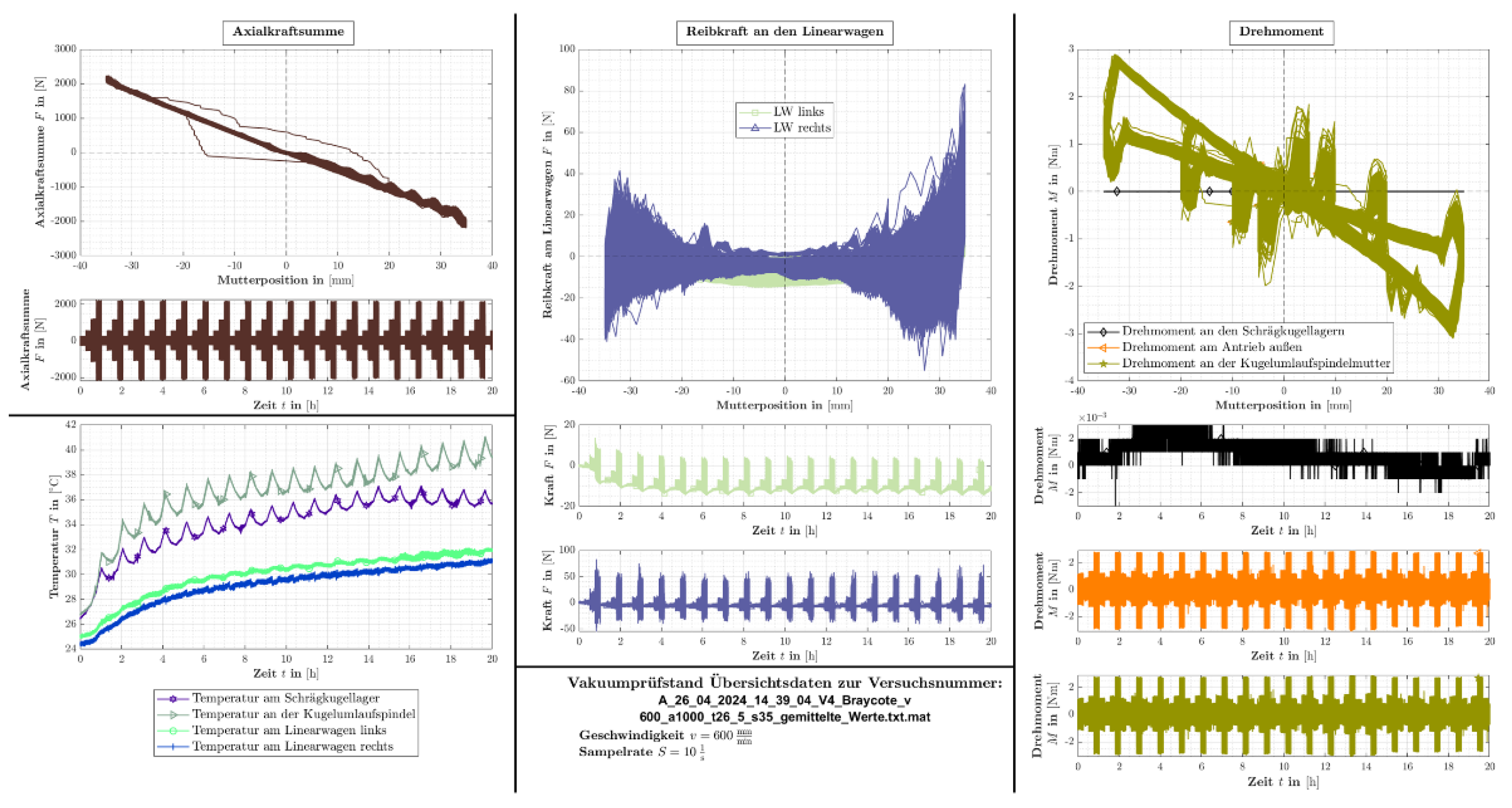
Figure 13 shows the results of all measurement channels for the Braycote lubricant. In this run, the normal force on the ball screw was increased in four stages up to ±2.1 kN. This load increase cycle was repeated 21 times within 20 h (
Figure 13, top left). The graphs at the bottom left show the temperatures of the individual components. Here, it can be seen that the temperature of the ball screw and the angular contact ball bearing are significantly higher than those of the two linear carriages. The temperature of the spindle rises again from the 16th hour, which indicates an imminent failure of this component. In contrast, the temperature of the angular contact ball bearing stabilizes, which is more indicative of normal operation. The load on the linear slide also results from the travel position. The force generates a load torque on the carriage. The friction force level on the left linear slide decreases slightly at the beginning (center, second diagram from the bottom). The friction force peaks on the right-hand linear carriage decrease slightly at the beginning, but also increase slightly again after approx. 17 h (center, bottom diagram).
Compared to the temperature measurements, the torques of the individual components and the overall drive are not as meaningful. Hardly any changes are recognizable here. The torque of the angular contact bearings (black curve, right, center) appears to decrease slightly over the test period, which correlates with the stabilization of the temperature. The torque on the spindle nut (green color) and also the total friction torque measured on the drive (orange curve) do not change.
The mass loss on the ball screw amounted to 55 mg at the end of the test. The mass of the two angular contact ball bearings decreased by 2.2 mg and 3.9 mg, respectively. Although the linear carriages were inconspicuous in terms of friction, the greatest mass losses were measured here at 106 mg (left) and 100 mg (right).
The test result shows that the spindle lubrication is the potential weak point. In a further test, the amount of grease on this component is now increased. If this is not effective, the load must be reduced, which can be achieved, for example, by increasing the size by one size.
6. Discussion, Conclusions, and Outlook
The testing of lubricants for applications in cleanrooms and under high vacuum (e.g., pharmaceuticals, aerospace, chip production) is a challenging task. The results of model tests (Cat. VI) are often not transferable to real applications, as the load collectives and boundary conditions in the components cannot be reproduced well enough. Complex aggregate tests (Cat. III) can only be carried out by a few specialized testing institutes and are extremely time-consuming and therefore expensive. As the volumes in this special niche segment are also very low, it is hardly possible to develop a cost-effective and yet application-oriented and individualized solution. The innovative vacuum test bench presented in this paper with a test cassette containing various mechanical design elements closes this gap.
For the first time, the tribological performance and characterization of high-performance lubricants based on ionic liquids can be documented, analyzed, and evaluated with high precision under cleanroom and vacuum conditions using a variety of measured variables on a universal component test bench (test class IV). The multifunctional design in combination with state-of-the-art measurement technology enables the desired transferability of the results to various practical applications.
Based on the new laboratory testing facilities now available, new types of ionic fluids are being investigated which represent a genuine alternative to the PFPE or MAC oils previously used in this area. In particular, the replacement of perfluoroorganic lubricants, materials, and coatings is urgently needed not only due to a potential restriction of PFAS-containing compounds in many of the above-mentioned areas, but also since end customers already expect PFAS-free solutions from suppliers. The physical–chemical and tribological tests presented here show that already the plain ionic liquids discussed here show the potential to outperform commercially available vacuum lubricants. The corrosive effects by ILs are a drawback that is investigated by employment of dedicated methods, and strategies for corrosion mitigation are currently elaborated. Overall, the blending of ILs offers an immense amount of fluid combinations for controlling the individual properties; the use of vacuum-compatible additives and the employment of rheological modifiers furthermore depict a huge toolbox for the development of tailor-made high-performance lubricants for all different kinds of lubricant applications that require outstanding material cleanliness.


