Article

Research on Sudden Unbalance Response of Rigid-Elastic-Oil Coupled Ball Bearings

School of Mechatronics Engineering, Henan University of Science and Technology, Luoyang 471003, China
*
Author to whom correspondence should be addressed.
Lubricants 2024, 12(5), 161; https://doi.org/10.3390/lubricants12050161
Submission received: 30 March 2024 / Revised: 26 April 2024 / Accepted: 1 May 2024 / Published: 6 May 2024

Abstract

:
(1) Background: To better understand the dynamic characteristics of a ball bearing with an elastic ring squeeze film damper (ERSFD) under sudden unbalance, a novel dynamic model was established by fully considering the coupling between the ERSFD, bearing outer ring (the journal), rotor, and disc (loading bearing); (2) Methods: An improved secant method was developed to determine the initial eccentricity values of the bearing’s outer ring and the disc. The dynamic response of the outer ring under different speed ratios, damping ratios, and mass ratios was solved using the variable-step Runge–Kutta method; (3) Results: In comparison, a low-speed ratio, high damping ratio, and low mass ratio were more conducive to suppressing the bearing vibration. When the imbalance was suddenly introduced, the displacement amplitude of the eccentricity, transmissibility, amplitude–frequency response, and the radius of the outer ring center locus increased; (4) Conclusions: This work provides a reference for further studying the nonlinear vibration of rolling bearings coupled with an ERSFD.

1. Introduction

For improved thrust-to-weight ratio and combat maneuvering, aero-engines are expected to have a low weight, low support stiffness, and wide support span. The rotor system of an aero-engine is equipped with a high-speed rolling bearing as a support device, the mechanical characteristics of which significantly influence the dynamic characteristics of the rotor system.
When subjected to unbalanced excitation proportional to the square of the rotor speed, a coupled system comprising a squeeze film damper (SFD), a high-speed rolling bearing, and a rotor with a highly nonlinear oil film force will exhibit complex nonlinear characteristics. In addition, the structure can cause a large displacement of the rotor and impact load on the main bearing under abnormal working conditions characterized by unbalanced loads, leading to intensified bearing vibration and high internal stress on the rotating parts. Excessive displacement can easily cause friction between the journal and the casing and even engine damage. Moreover, studies have shown that the rotor system of an aero-engine is easily affected by nonlinear factors such as the bearing radial clearance [1,2], number of rolling elements, time-varying stiffness [3], Hertz contact load, and channel characteristic parameters [4,5]. On the other hand, the main bearing coupled with an ERSFD can effectively suppress the unsteady response of the rotor system, though such a damper affects the dynamic performance of the main bearing [6,7]. Hence, for a more accurate prediction of the dynamic behavior of the main bearing, it is necessary to study the dynamic characteristics of a ball bearing with an ERSFD under a sudden unbalanced condition.
The vibration caused by an imbalance significantly influences the dynamic characteristics of a bearing–rotor system with a high DN value [8,9,10]. An oil film damper can attenuate the amplitude of vibration caused by residual imbalance and the external force of the casing. Many experts and scholars have studied the dynamic characteristics of an SFD–bearing–rotor system under a sudden imbalance. For example, Li et al. [11] studied the transient response characteristics of a single-disc rotor subjected to a sudden unbalance. Sun et al. [12] proposed a simulation method for the blade loss of a dual-rotor gas turbine engine considering the thermal growth effect, and the local nonlinearity of the bearings and SFD was fully considered and analyzed. Both the amplitude and final instability caused by sudden unbalance were found to increase with an increase in the sudden unbalance value [13,14]. Zhu et al. [15,16] compared, analyzed, and verified concentric and nonconcentric SFD-flexible rotor systems. The SFD had good anti-surge unbalance ability [17]; however, excessive unbalance can cause the system to produce a bistable jump, and the main resonance-type bistable phenomenon can be characterized by an amplitude jump and centroid steering. Combined with the response characteristics of the Duffing equation, Meng et al. [18] analyzed the nonlinear characteristics of the steady-state response of a flexible rotor–SFD bearing system with a centering spring. The effects of bearing parameters [19], stiffness ratio [20], unbalanced parameters [21,22], and mass ratio [23,24] on the bistable phenomenon and the size of the bistable region were analyzed and discussed. Finally, the design parameters and their combination of values within which the speed ratio could avoid or inhibit the bistable state were determined. Zhang et al. [25] studied the stability and bifurcation behavior of an SFD–sliding bearing–rotor system [24] and found the system to have steady-state periodic solutions, period-doubling bifurcation, and almost periodic motion. Gjika et al. [26] conducted theoretical analysis and experimental research on a similar system and found that the system contains subharmonic components. Xu [27] studied the dynamic characteristics of an SFD–rotor system under maneuvering flight and proved that the damper could effectively suppress transient vibration and play a role in quickly stabilizing rotor operation.
Based on an infinitely differentiable real function, Meng [28] analyzed the sudden unbalanced response of flexible rotors supported on concentric and nonconcentric SFDs. The results showed that the SFD could suppress sudden unbalance. The nonconcentric SFD outperformed the concentric one in resisting unbalance when introduced suddenly; however, it could easily produce a non-coordinated response. Based on Floquet’s theorem, nonlinear dynamics, and bifurcation theory, Heidari [29] studied the stability and bifurcation problem of the unbalanced response in rigid rotors supported by an SFD with asymmetric concentrated springs. The asymmetrically supported rotor [30] produced undesirable asynchronous vibration. In all the above studies, the influence of relevant parameters on the dynamic characteristics of rotors was considered by introducing the oil film force generated through the SFD [31,32,33,34]. The conventional SFD has a high degree of nonlinearity, which can cause the rotor system to have a multi-solution and multi-frequency vibration response, eventually leading to increased external force and periodic fatigue of the rotor. Moreover, the SFD is highly nonlinear. In addition to the selection of the elastic support stiffness [35] and SFD parameters [36], an important determining factor is the rotor unbalance [37,38], particularly the sudden unbalance caused by blade loss, which has hindered studies on problems related to SFD–bearing–rotor systems.
The ERSFD, which is an advanced version of the SFD, significantly improves the high nonlinearity of the squeeze oil film owing to elastic ring deformation and complex fluid–structure coupling. Scholars have investigated the dynamic characteristics of ERSFD–bearing–rotor systems under sudden unbalance. Han et al. [39] studied the dynamic response of an ERSFD–rotor system, and the installed ERSFD could effectively suppress the nonlinear bistable response of the SFD-supported rotor, significantly reduce the transient amplitude caused by sudden excitation, shorten the resulting transient vibration process, and avoid the “soft” jump response of the rotor. Zhou et al. [40,41] fully considered the coupling effect between the rotor and a floating ring squeeze oil film damper (FSFD) [42] and studied the inhibition effect of the FSFD on the sudden unbalanced response of the rotor system. The FSFD could better suppress the transient unbalanced response of the rotor system than the conventional oil film damper (TSFD), and the greater the floating ring mass, the better the transient unbalanced response of the rotor system. Zhang et al. [43] designed and built a rotor dynamic test platform for ERSFD to quantitatively analyze the vibration response of the rotor system during acceleration and deceleration under the condition of oil supply and no oil supply by the damper under sudden unbalanced loading. The ERSFD could effectively suppress the transient response caused by the sudden unbalance and significantly reduce the additional vibration caused by sudden unbalance. However, regardless of whether the elastic ring is fixed [39] or not [40,41,42], there will be a coupled bearing excitation, and the dynamic characteristics of the rotor are analyzed. Yang et al. [44] established an integrated dynamic model of ERSFD-ball bearing considering the bearing excitation and analyzed the effects of bearing speed and squirrel cage stiffness on the dynamic response of the journal. The results showed that an appropriate increase in bearing speed was conducive to the journal stability. Li et al. [45] established a rigid-elastic-liquid (REL) coupled ball bearing structure considering the unbalanced excitation of the rotor, and they further analyzed the influence of typical structural parameters (the bearing speed, squirrel cage stiffness, and the elastic ring flexibility coefficient) on the dynamic characteristics of the bearing’s outer ring. The results showed that compared with the traditional squeeze film damper (SFD) system, the ball bearing with REL coupling structure was more stable, and the vibration damping effect was better under higher bearing speed, lower squirrel cage stiffness, and smaller elastic ring flexibility coefficient. To sum up, there are few reports on the dynamic characteristics of the bearing’s outer ring when the ERSFD ball bearing structure based on the rotor system is subjected to sudden unbalance.
In this study, to thoroughly understand the dynamic characteristics of the bearing’s outer ring with an ERSFD based on the rotor system under sudden unbalance, in view of the complexity and particularity of the structure (the outer ring of the bearing is integrated with the centering squirrel-cage elastic support), the coupling between the ERSFD, outer ring of the bearing, rotor, and disc were fully considered. A dynamic model of the system under sudden unbalance was established. Based on the principle of virtual work, the oil film force was solved using the central finite difference method and the double-integral method. On this basis, a dynamic differential equation of motion was solved using the Runge–Kutta method. The dynamic response of the bearing’s outer ring was studied for the first time under different speed, damping, and mass ratios.

2. Dynamic Model of Ball Bearing with ERSFD

The coupling between the main bearing and the ERSFD makes the dynamic characteristics of the main support system become more complex under sudden unbalance. In addition, the bearing is an important part of the rotor system, and its dynamic performance directly affects the performance of the rotor system. Different from the previous studies focusing on the dynamic response of the rotor under a sudden unbalance, this study mainly focuses on the dynamic characteristics of the bearing’s outer ring under sudden unbalance.
In Figure 1a, O b is the bearing center, O j is the center of the journal, Y O b Z is the Cartesian coordinate system, O j precesses synchronously about O b at an angular velocity Ω , R is the radius of the journal, φ b is the attitude angle of the journal, ω is the angular velocity of the journal, C 1 is the radial clearance of the inner cavity oil film, e b is the eccentricity between O b and O j , θ is the angle of the start of positive pressure region measured from the center line. Here, r indicates the radial squeeze direction, t is the direction of circumferential orbital motion, and β is the installation angle of the first inner boss, which is used to realize the circumferential positioning of the elastic ring.
From the model shown in Figure 1b–d, a motion differential equation of the structure coupled with an ERSFD and a ball bearing under sudden unbalance can be derived using Newton’s second law as follows:
m b e ¨ b e b φ ˙ b 2 = i = 1 N T i cos φ b θ i + F d r F r K y y sin φ b + G b + K z z cos φ b m b e b φ ¨ b + 2 e ˙ b φ ˙ b = F d t F t K y y cos φ b G b + K z z sin φ b m d e ¨ d e d φ ˙ d 2 = G d cos φ d + F a r F s r + F u cos ω t φ d m d e d φ ¨ d + 2 e ˙ d φ ˙ d = G d sin φ d + F a t F s t + F u sin ω t φ d
where m b is the vibration mass concentrated at the journal (including the masses of the bearing, damper, and rotor), G b is the gravity of the journal, F r is the radial oil film force, F t is the circumferential oil film force, F d r is the radial component of the elastic force acting on the journal, F d r = 0.5 K s e d cos φ d φ b e b , F d t is the tangential component of the elastic force acting on the journal, F d t = 0.5 K s e d sin φ d φ b , T i indicates the support reaction at the boss of the elastic ring, T i = k e r e b cos θ i φ b , k e r is the elastic ring stiffness, N is the number of inner bosses in the elastic ring, θ i is the angle between the i t h inner boss and the negative direction of the Z-axis, θ i = β + 2 i 1 π / N , K y is the squirrel cage stiffness in the Y-axis direction, K z is the squirrel cage stiffness in the Z-axis direction, y and z represent the offset distance of O j in the Y O b Z plane, G d is the gravity of the disc, F s r is the radial component of the elastic force acting on the disc, F s r = K s e d e b cos φ d φ b , e b is the eccentricity between O b and O 1 , O 1 is the center of the disc, φ d is the azimuth of the disc, F s t is the tangential component of the elastic force acting on the disc, F s t = K s e b sin φ d φ b , K s is the stiffness of the shaft, F a r is the radial component of the external damping force acting on the disc, F a r = 2 ζ m d ω c e ˙ d , ζ is the damping ratio, ω c is the critical angular velocity of the rotor system, ω s = K s / m d , m d is the vibration mass at the disc, F a t is the tangential component of the external damping force acting on the disc, F a t = 2 ζ m d ω c e d φ ˙ d , and F u represents the unbalanced forces concentrated on the disc.
In Equation (1), K y and K z are obtained using the finite element method, while F r and F t are determined from the oil film force generated via the ERSFD. Combined with Figure 1b and without considering the damping hole, the governing equation for the transient oil film pressure can be written as follows [46]:
1 R 2 θ h i 3 12 μ p θ + x h i 3 12 μ p x = Ω h i θ k e θ + h i t
Here, x is the axial coordinate, μ is the dynamic viscosity of the oil, h i is the oil film thickness in the inner cavity, and k e is the deformation amount of the elastic ring.
The main solution to the oil film force of the ERSFD is the elastic ring deformation. Based on the structural characteristics of the built model and the principle of virtual work, the radial deflection corresponding to any angular position [47,48] can be expressed in a series form as follows:
k e ϕ m = Γ i = 1 N q i π ϕ m sin ϕ m + 1 2 ϕ m π 2 π 2 3 3 2 cos ϕ m 2
where Γ is the flexibility coefficient of the elastic ring, q i is the force applied to the inner boss, q i = T i , q i = k e r e b cos θ i φ b , k e r is the stiffness of the elastic ring, ϕ m is the difference between the position angle of the ith boss force and the position angle of the radial deflection point on the elastic ring, ϕ m = θ i φ b + π + θ , and 0 ϕ m 2 π .
According to Equations (2) and (3), the following relationships can be obtained:
h i = C 1 + k e θ + e b cos θ h i / θ = k e / θ e b sin θ h i / t = k ˙ e + e ˙ b cos θ
where
k e θ = Γ i = 1 N 1 2 q i sin ϕ m ϕ m π 2 π 2 3 + 1 2
k ˙ e = Γ i = 1 N k e r χ π ϕ m sin ϕ m + 1 2 ϕ m π 2 π 2 3 3 2 cos ϕ m 2
χ = e ˙ b cos θ i φ b + φ ˙ b e b sin θ i φ b
Combined with Equations (2)–(4), the five-point central finite difference method and double-integral method were used to solve for the oil film force. With this, the formulae for solving F r and F t can be expressed as follows:
F r e b , e ˙ b , φ b , φ ˙ b = L b R θ 1 θ 2 P θ cos θ φ b d θ F t e b , e ˙ b , φ b , φ ˙ b = L b R θ 1 θ 2 P θ sin θ φ b d θ
where L b is the length of the damper, θ 1 and θ 2 are the upper and lower boundary angles for integrating the oil film pressure, respectively.
Equation (5) is substituted into Equation (1), and the following dimensionless factors are introduced: ω y = ω s y / ω , ω z = ω s z / ω , ω s = ω s c / ω , ω t = ω e r / ω , ω s y = K y / m b , ω s z = K z / m b , ω s c = k s c / m b , and ω e r = k e r / m b . Here, k s c indicates the stiffness of the squirrel cage, and k e r is the stiffness of the elastic ring. Assuming that the squirrel cage is supported by a symmetric stiffness, then K y = K z = k s c , ω s y = ω s z , and ω y = ω z . Furthermore, a is the mass ratio, a = m b / m d , ε b = e b / C 1 , ε d = e d / C 1 , ζ is the damping ratio, ζ = C d / C c , C d is the external damping coefficient, C c is the critical damping coefficient, ω ¯ = G b / m b C 1 ω c 2 = G d / m d C 1 ω c 2 , C c = 2 m d ω c , ω c is the critical speed of the rotor, λ is the speed ratio, λ = ω / ω c , τ = ω t . · · is the d / d t operator, and · is the d / d τ operator. The dimensionless motion differential equation of the structure coupled with the ERSFD and ball bearing under a sudden unbalanced condition is as follows:
ε b = F r m b C 1 ω 2 ω t 2 ε b i = 1 N cos 2 φ b θ i + ε b φ b 2 ω s 2 + ω ¯ λ 2 cos φ b + 1 2 a λ 2 ε d cos φ d φ b ε b φ b = 1 ε b 2 ε b φ b F t m b C 1 ω 2 ω ¯ λ 2 sin φ b + 1 2 a λ 2 ε d sin φ d φ b ε d = ε d φ d 2 + ω ¯ λ 2 cos φ d 1 λ 2 ε d ε b cos φ d φ b 2 ζ λ ε d + U t cos ω t φ d φ d = 1 ε d 2 ε d φ d ω ¯ λ 2 sin φ d 1 λ 2 ε b sin φ d φ b 2 ζ λ ε d φ d + U t sin ω t φ d
For Equation (6), since the sudden unbalanced changes in the actual operation of an aero-engine are continuous, an infinitely differentiable real function [28] is introduced:
β γ , s t = t T γ , s t d t / T γ , s t d t
In Equation (7), when γ and s are infinitely close, β γ , s t is infinitely close to the step function. In this case, the dimensionless form of the unbalanced parameter U t of the system can be expressed as follows:
U t = U 0 + U d β γ , s τ
where U 0 is the unbalance before adding the sudden unbalance, U d is the sudden unbalance, β γ , s t = 1 , t γ 0 , t γ , then γ and s indicate the start and end times of the sudden unbalance, respectively.
To solve Equation (6), determining the disc eccentricity ε d and the journal eccentricity ε b is key to the iterative process of the equation. An iterative algorithm different from the basic secant method is used to establish the functional relationship between the assumed eccentricity ε and the calculated unbalanced amplitude r A (referring to e b and e d , here, e d is taken as an example). Based on this, the slope of two consecutive iterations can be obtained.
η n = 1 C 1 r A _ n r A _ n 1 ε n ε n 1
where
r A = C 1 ε d cos ( π / 2 φ d ) 2 + C 1 ε d cos π φ d m d g k s + k e r 2
Substituting Equation (9) into the improved secant method [49], the following equation can be obtained:
ε n + 1 = η n ε n + γ A _ n / C 1 1 + η n
Introducing variables S 1 = ε b , S 2 = ε b , S 3 = φ b , S 4 = φ b , S 5 = ε d , S 6 = ε d , S 7 = φ d , S 8 = φ d , and S 9 = τ , and combining with Equation (8), Equation (6) can be transformed into a nine-dimensional autonomous nonlinear system:
S 1 = S 2 S 2 = F r m b C 1 ω 2 ω t 2 S 1 i = 1 N cos 2 S 3 θ i + S 1 S 4 2 ω s 2 + ω ¯ λ 2 cos S 3 + 1 2 a λ 2 S 5 cos S 7 S 3 S 1 S 3 = S 4 S 4 = 1 S 1 2 S 2 S 4 ω ¯ λ 2 sin S 3 + 1 2 a λ 2 S 5 sin S 7 S 3 F t m b C 1 ω 2 S 5 = S 6 S 6 = S 5 S 8 2 + ω ¯ λ 2 cos S 7 1 λ 2 S 5 S 1 cos S 7 S 3 2 ζ λ S 6 + U 0 + U d β γ , s S 9 cos S 9 S 7 S 7 = S 8 S 8 = 1 S 5 2 S 6 S 8 ω ¯ λ 2 sin S 7 1 λ 2 S 1 sin S 7 S 3 2 ζ λ S 5 S 8 + U 0 + U d β γ , s S 9 sin S 9 S 7 S 9 = 1
Importantly, ε b and T can effectively characterize the instantaneous dynamic response characteristics of the outer ring. Here, the transmissibility T is the ratio of the external transmission force through the damping support to the unbalanced excitation force of the equivalent system. The external force is generally the vector sum of the supporting oil film force and the supporting elastic force. In this case, the solution formula is as follows:
T = F E R S F D + F c s F u
where F E R S F D is the squeeze oil film force, and F c s is the centering spring force.

3. Numerical Analysis and Solving Process of the Model

3.1. Solving Process

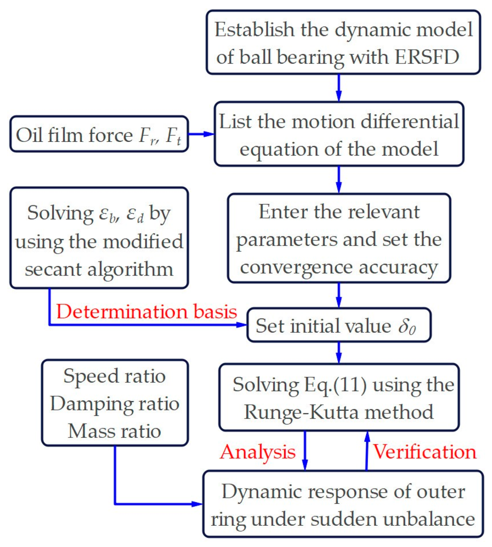
Figure 2 shows the flowchart for solving the dynamic characteristics of the structure coupled with the ERSFD and ball bearing under sudden unbalance. Here, ε b and ε d are determined using the improved secant algorithm. The initial value δ 0 is set by referring to the determined ε b and ε d . The oil film forces F r and F t generated via the ERSFD are introduced, and the fourth- and fifth-order variable-step Runge–Kutta method is used to solve Equation (11) by referring to Table 1. The dynamic characteristics of the bearing’s outer ring under sudden unbalance were analyzed based on numerical analysis techniques (time-domain waveform, outer-ring center locus, Poincaré map, spectrum, and transmissibility). Table 2 presents the parameter values.

3.2. Numerical Analysis

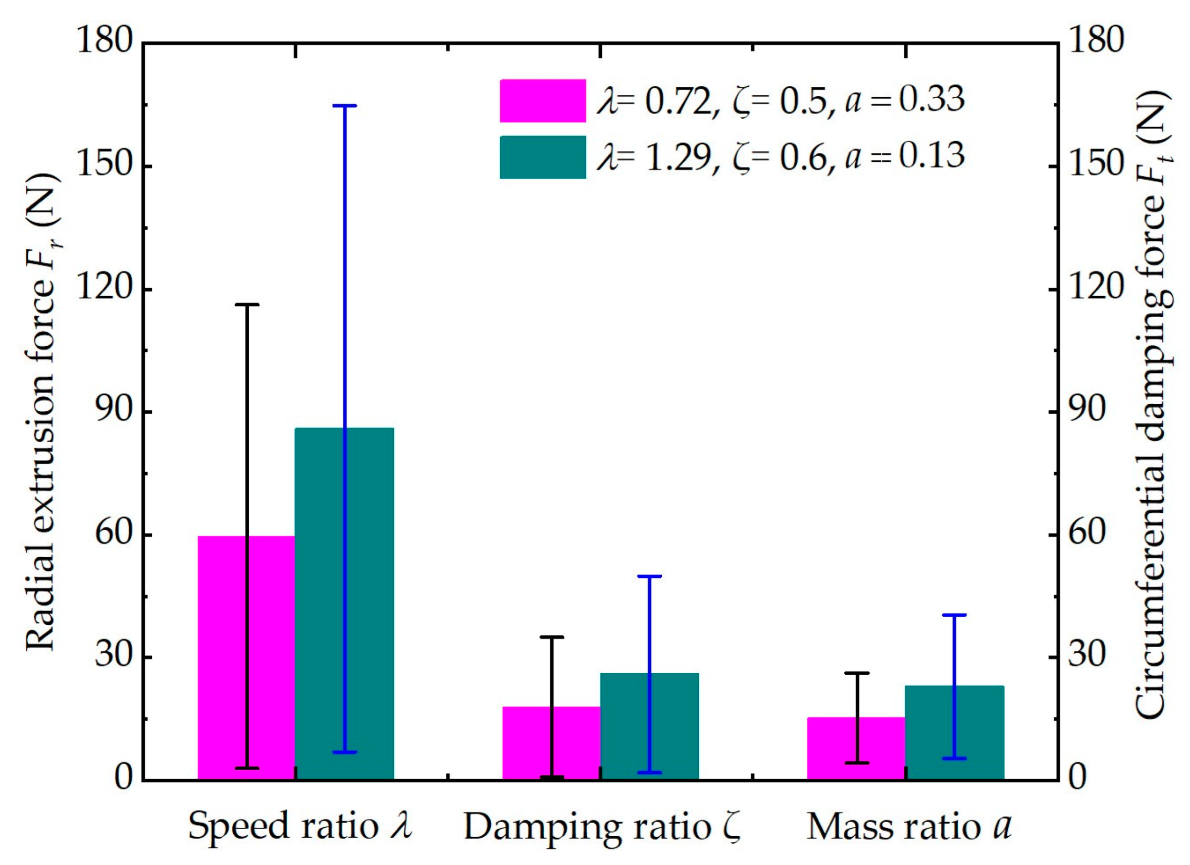
The ERSFD and ball bearings are coupled with each other, and the ERSFD produces a nonlinear oil film force on the bearing’s outer ring, which ultimately affects the dynamic response characteristics of the bearing. The free precession of the bearing outer ring causes a deformation of the elastic ring, which automatically adjusts the oil film clearance, indirectly changing the oil film pressure distribution and thereby altering the oil film force. In addition, due to the introduction of parameters, such as the damping ratio ζ , speed ratio λ , and mass ratio a , the dynamic response of the bearing becomes more complicated. In view of this, it is necessary to analyze the effects of the damping, rotational speed, and mass ratios on the oil film force introduced by the ERSFD in combination with Table 2.
Here, taking U t = 0.6 as an example, the length of the error bar in Figure 3 represents the change in the simulation value, and the longer the error bar, the greater the change amplitude of the radial squeeze force F r and the circumferential damping force F t . The data reveal that the speed ratio has the greatest influence on the oil film force, whereas the mass ratio has the least influence on the oil film force.

4. Results and Discussion

4.1. Influence of Speed Ratio

Figure 4 shows the dynamic response of the outer ring varying with the speed ratio when the unbalanced U t is 0.4. In Figure 4a, for λ values of 0.72 and 1.29, the amplitudes of the eccentricity ε corresponding to the steady state are 0.18 and 0.33, and the greater the amplitude, the longer the transient response time Δ τ before entering the steady state. In Figure 4b, with the increase in the speed ratio, the transmissibility T increases, whereas the amplitude changes little. Figure 4c,d shows that with the increase in the speed ratio, the radius of the outer ring center locus increases, and the intersection point between the outer ring center locus and the Poincaré section is distributed on a line. The center locus of the outer ring is unstable in the initial stage and gradually becomes stable and moves periodically with its continuous operation. Figure 4e,f reveal that the Y and Z displacements of the outer ring have a double-frequency component 2 f 0 ( f 0  is the fundamental frequency of the rotor rotation). When λ = 1.29, there is also a subharmonic ( f 0 ± f 0 / 3 ) vibration, which eventually causes instability of the outer ring center locus, as shown in Figure 4c,d, during the initial operation stage.
Figure 5 shows the relationship between the dynamic response of the outer ring and the speed ratio λ when U t = 0.6 . The data in Figure 5 show that the variation rules of its time-varying displacement, transmissibility, outer ring center locus, Poincaré map, and spectrum are similar to those shown in Figure 4. The difference is that in Figure 5d, when λ = 1.29 , the outer ring center locus and Poincaré section almost intersect at a fixed point, and the bearing outer ring exhibits periodic precession and good stability. In addition, a comparison between Figure 4 and Figure 5 shows that as the unbalance U t increases, the dynamic response time Δ τ before the steady state is shortened, and the time-varying displacement, transmissibility, radius of the outer ring center locus, and the Y and Z displacement amplitudes increase. The greater the rotational speed ratio, the greater the change in the amplitude. In summary, a lower speed ratio is more conducive to suppressing the bearing vibration.

4.2. Influence of Damping Ratio

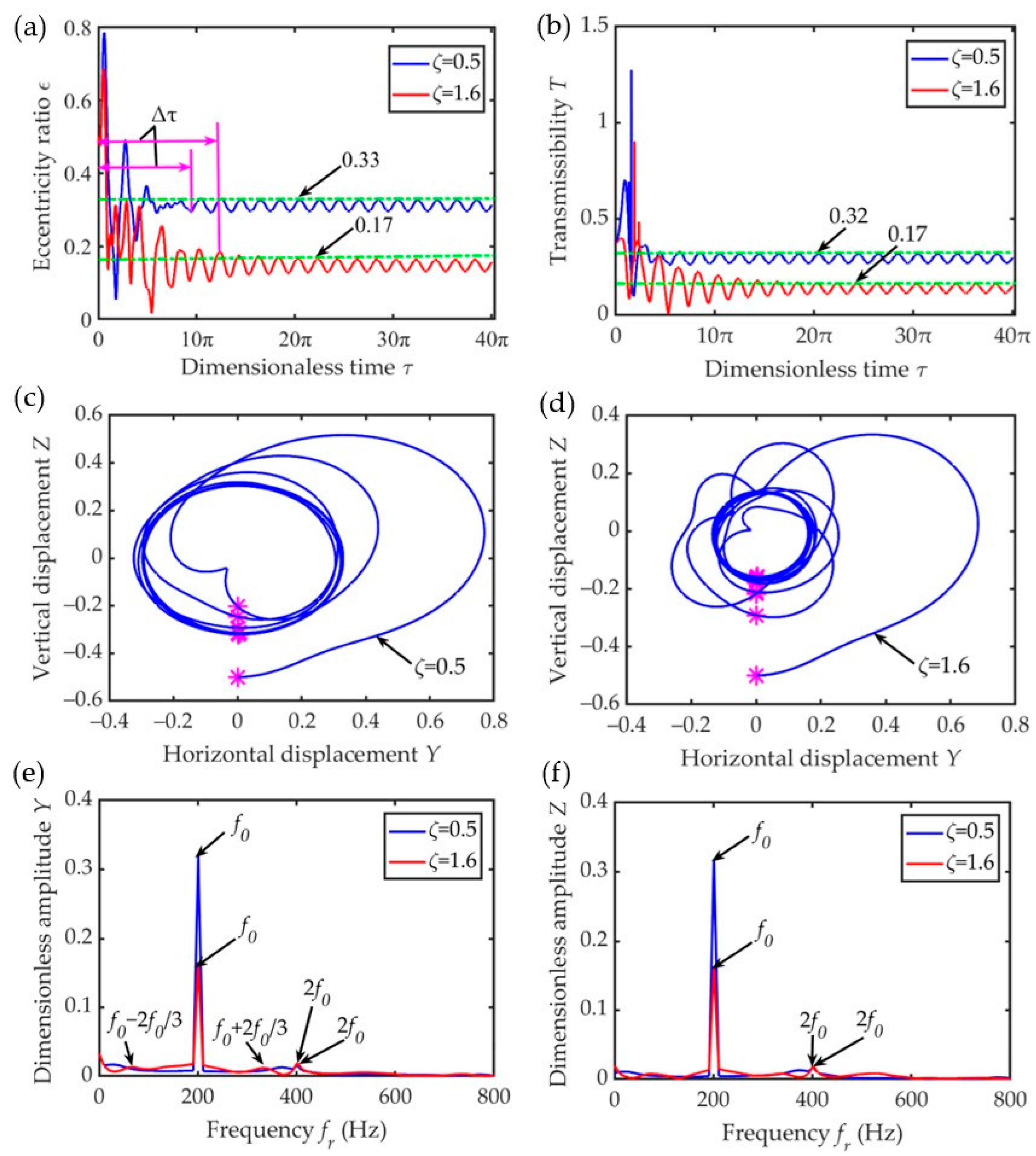
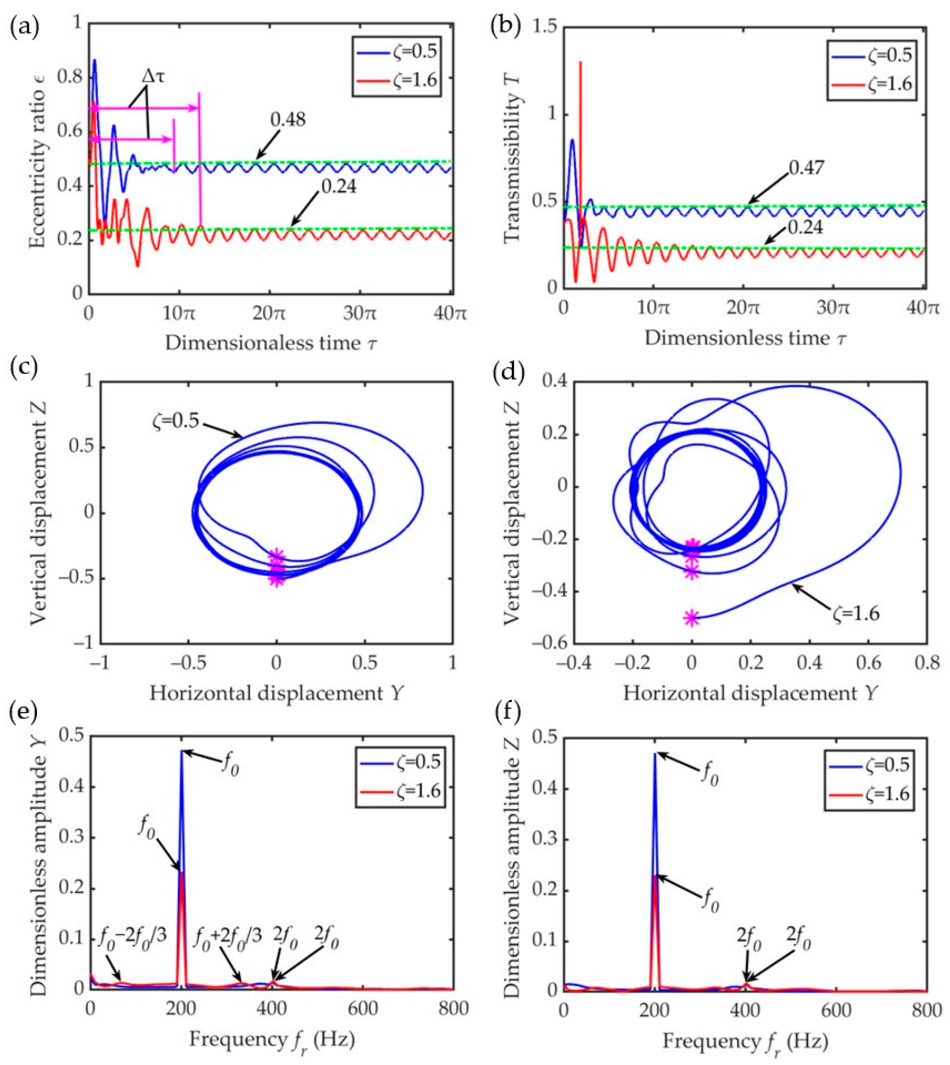
Figure 6 and Figure 7 reveal the relationship between the dynamic response of the outer ring and the damping ratio based on different unbalanced values. By comparing and analyzing Figure 6 and Figure 7, under the same unbalance, as the damping ratio ζ increases, the amplitude of the eccentricity ε decreases. Therefore, the transient response time Δ τ before entering the steady state is relatively long. Similarly, the radius of its center locus, transmissibility, and displacement amplitude in the Y and Z directions also decrease. As shown in (c) and (d) of Figure 6 and Figure 7, the intersection points between the center locus of the outer ring and the Poincaré section are distributed on a line segment. In the initial operation stage, the movement of the outer ring is unstable and finally tends to stabilize. In addition, there is a double-frequency component in the Y and Z displacements. When ζ = 1.6 , there is also a subharmonic ( f 0 ± 2 f 0 / 3 ) vibration in the spectrum of displacement Y.
In a nutshell, due to the existence of multiple frequency components, the motion state of the outer ring is complicated in the transient response stage. Moreover, increasing the unbalance has relatively little effect on the dynamic response of the outer circle. However, if the unbalance remains unchanged, the greater the damping ratio, the greater the degree of inhibition of the motion of the outer ring, resulting in a reduction in the steady-state response amplitude, which is more beneficial for suppressing the bearing vibration.

4.3. Influence of Mass Ratio

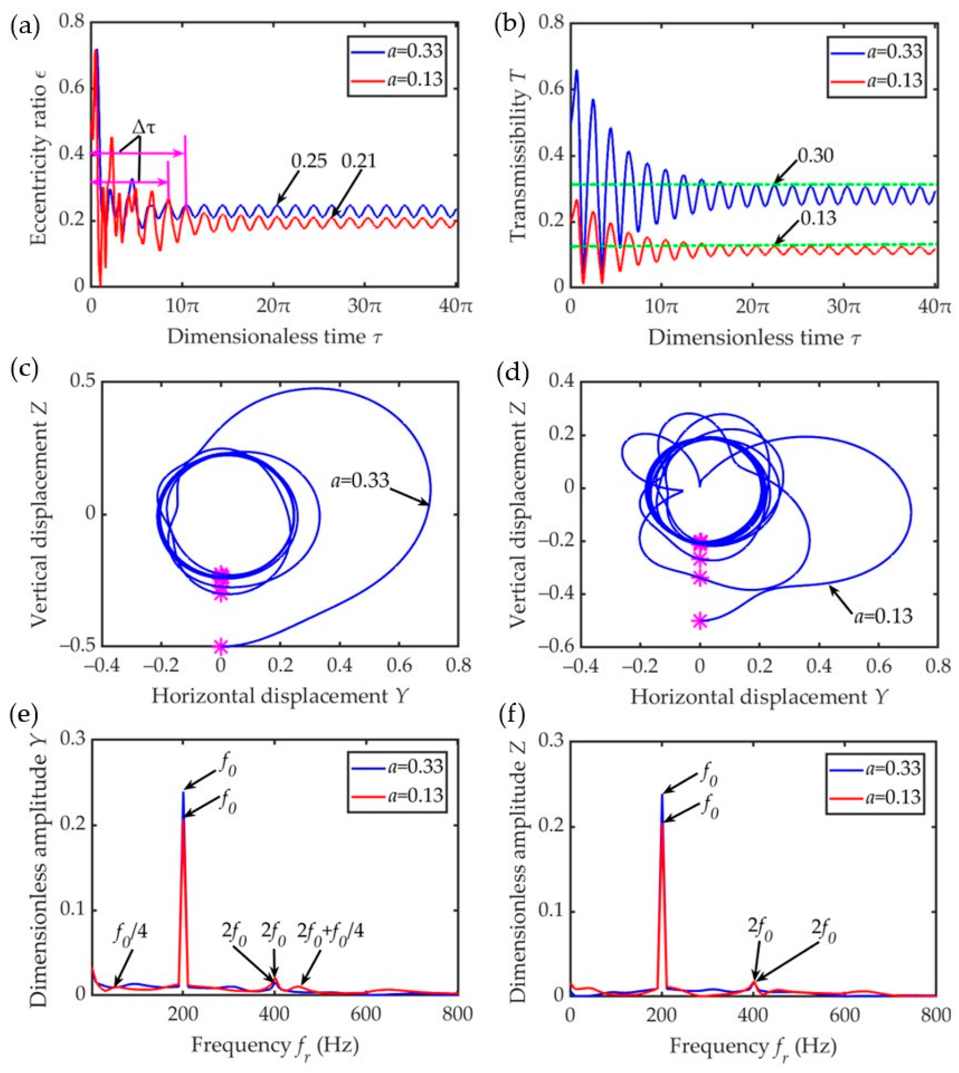
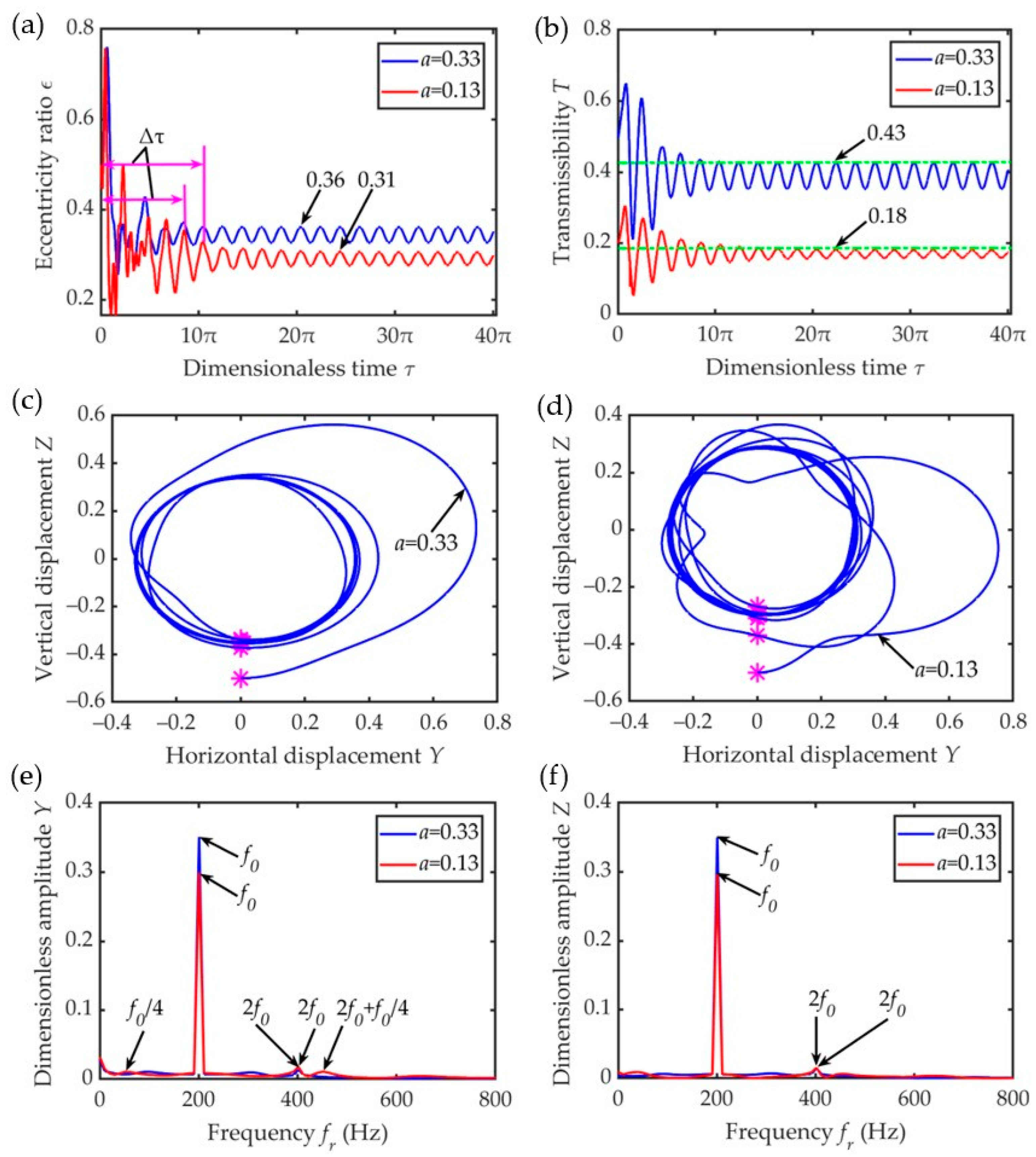
Figure 8 and Figure 9 show the relationship between the dynamic response of the bearing outer ring and the change in the mass ratio when the unbalanced values are U t = 0.4 and 0.6. Clearly, when the unbalance is equal, the greater the mass ratio a , the shorter the transient response time of the eccentricity amplitude, as shown in Figure 8a and Figure 9a. At higher mass ratios, the radius of the center locus of the outer ring, the transmissibility, and the amplitudes of the Y and Z displacements all decrease. When a = 0.33 , regardless of the initial point, the outer ring center locus and Poincaré section intersect at a fixed point, and the bearing’s outer ring exhibits periodic precession. When a = 0.13 , the intersection points between the center locus of the outer ring and the Poincaré section are distributed on a line segment, and the motion state of the outer ring eventually becomes stable from the instability state in the initial stage. Because the amplitude–frequency response amplitude has many components, such as the fundamental frequency, frequency doubling, and frequency rotation, the motion of the outer ring is less stable in the initial operation stage compared with that at high mass ratios. When compared with Figure 8 and Figure 9, the radius of the outer ring center locus, the amplitude of the eccentricity, transmissibility, and Y and Z displacements all increase. This is due to the increase in the unbalance excitation, and the greater unbalance helps improve the stability of the system. Therefore, the vibration reduction effect at low mass ratios is relatively good.

5. Test Verification

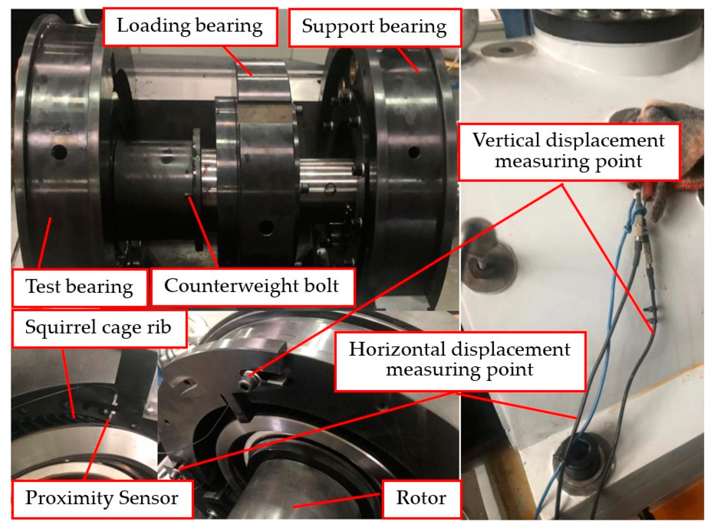
A test bench, as shown in Figure 10, was set up based on the established model, and the feasibility and rationality of the model were verified by comparing and analyzing the test and model simulation data of the outer ring center locus under a sudden unbalanced condition. The driving system makes the main body of the testing machine rotate at a certain speed, and the lubrication system provides oil lubrication for the bearing. According to the test requirements, a load was applied to the bearing using the loading system. An electrical measurement and control system and a computer detection system were used to measure and control the entire test process.
Figure 11 shows the unbalanced simulation and measuring point of the precession displacement of the bearing outer ring. Two thread holes were symmetrically arranged on the rotating spindle near the test bearing. In the simulation of the unbalance test, a small screw was mounted on one of the thread holes to simulate the unbalance, and the value was measured using a dynamic unbalance measuring instrument. Subsequently, the screw was locked to simulate the unbalance test. The dynamic response of the ball-bearing’s outer ring with the ERSFD was simulated and analyzed by measuring the precession trajectory of the bearing’s outer ring. The precession trajectory of the outer ring was measured using a proximity sensor (model: PU-02A, Japan) located in the radial direction of the squirrel cage. The two proximity sensors were installed vertically. In terms of the measurement method, the passing frequency and passing position of the magnetic element were measured through the proximity sensor set placed directly above the radial direction of the squirrel cage, and the precession speed and motion trajectory of the outer ring were then calculated. The impact effect generated by the sudden unbalance was measured using the impact response factor (IRF). The IRF is the ratio of the transient response amplitude A t max to the steady-state amplitude A s max . In addition, during the operation of the system, the temperature is controlled using automatic heating and cooling devices. To ensure the safety and stability of bearing performance, the experiment employs lubricating oil with a consistent temperature of 40 °C, matching the simulated temperature of the model. This constant temperature aligns with the low-temperature viscosity measurement of the oil and effectively eliminates any potential impact on bearing dynamic characteristics.
When the bearing speed was 13,000 r/min ( λ = 1.05 ), which was close to the natural frequency of the rotor, the transient vibration response amplitude of the outer ring increased significantly, and the impact effect was evident. Therefore, during the measurement, the bearing speed was set to n b = 13,000 r/min, the screw masses were 2, 4, and 6 g, the sampling rate was not lower than 10,000 Hz, the resolution was 1 μm, the sampling length was 1 s , and the measurement range was 0–0.5 mm. To ensure the reliability and accuracy of the test data, each state was sampled five times, and the average value was taken.
From the test, it was demonstrated that when the screw mass was 2 g, the precession orbit radius of the bearing’s outer ring changed little compared with that without any screw mass. Taking the screw weighing 6 g, when the bearing speed was increased to n b = 13,000 r/min, the vibration of the testing machine was intensified, and a harsh sound was emitted, increasing the test risk. At this time, the operation of the testing machine was stopped, which made it difficult to collect the data. Therefore, only the test results corresponding to the bearing speed n b = 13,000 r/min and a screw mass of 4 g are presented herein. Finally, the test results were compared with the results obtained without the screw mass.
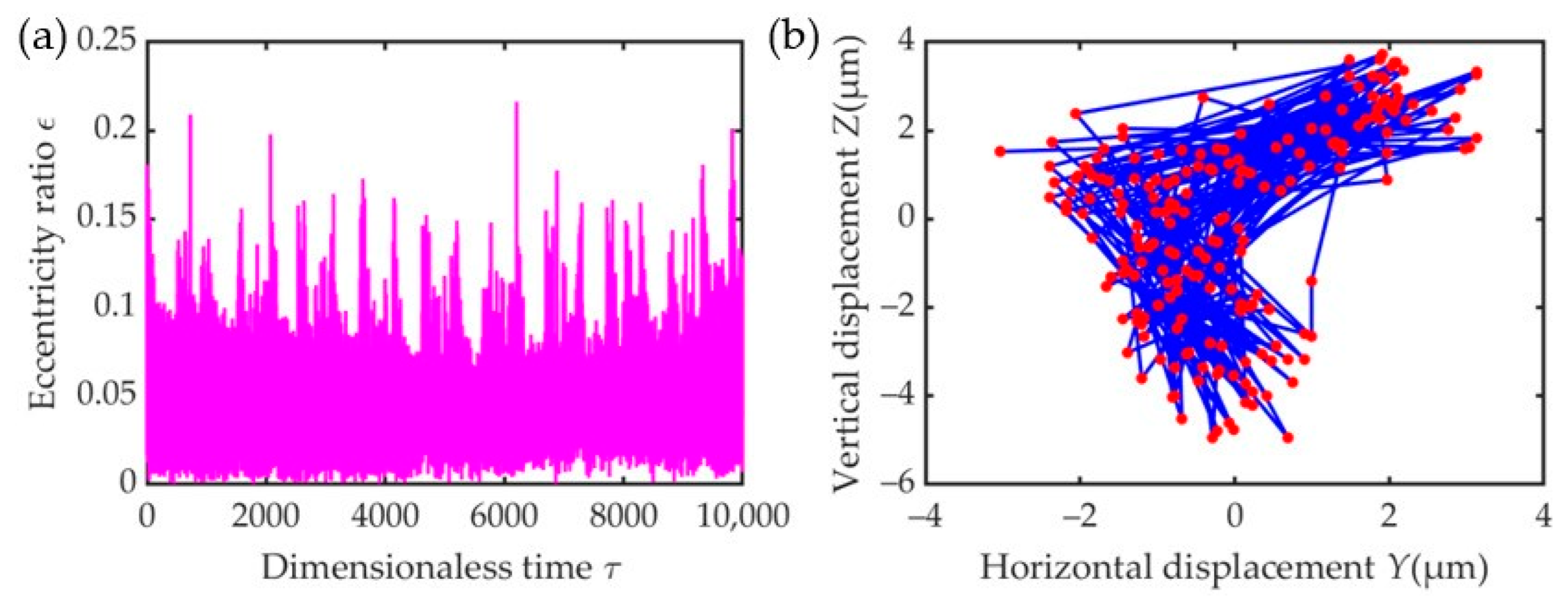
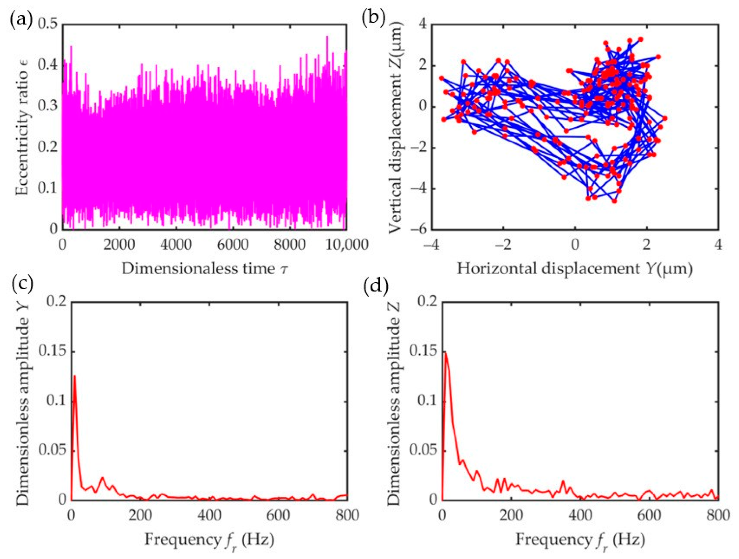
Figure 12 and Figure 13 show the test results without a screw and with a screw at n b = 13,000 r/min, respectively. In the steady state, when the screw mass is not added, the amplitude of the eccentricity ε in Figure 12a of the bearing’s outer ring is approximately 0.2, which is approximately 0.5 times less than that in Figure 13a when the screw mass is 4 g. In addition, as shown, when the screw mass is not added, i.e., in Figure 12b, the radius of the bearing’s outer ring center locus is very small, which can hardly be seen. When the screw mass is 4 g, i.e., in Figure 13b, the radius of the outer ring center locus increases significantly. This also suggests that at the same bearing speed, with the increase in the unbalance, the corresponding radius of the outer ring axis locus also increases. As can also be seen from Figure 13c,d, the presence of subharmonics leads to the relatively unstable motion of the bearing outer ring, as evidenced by its eccentricity amplitude fluctuation in Figure 13a.
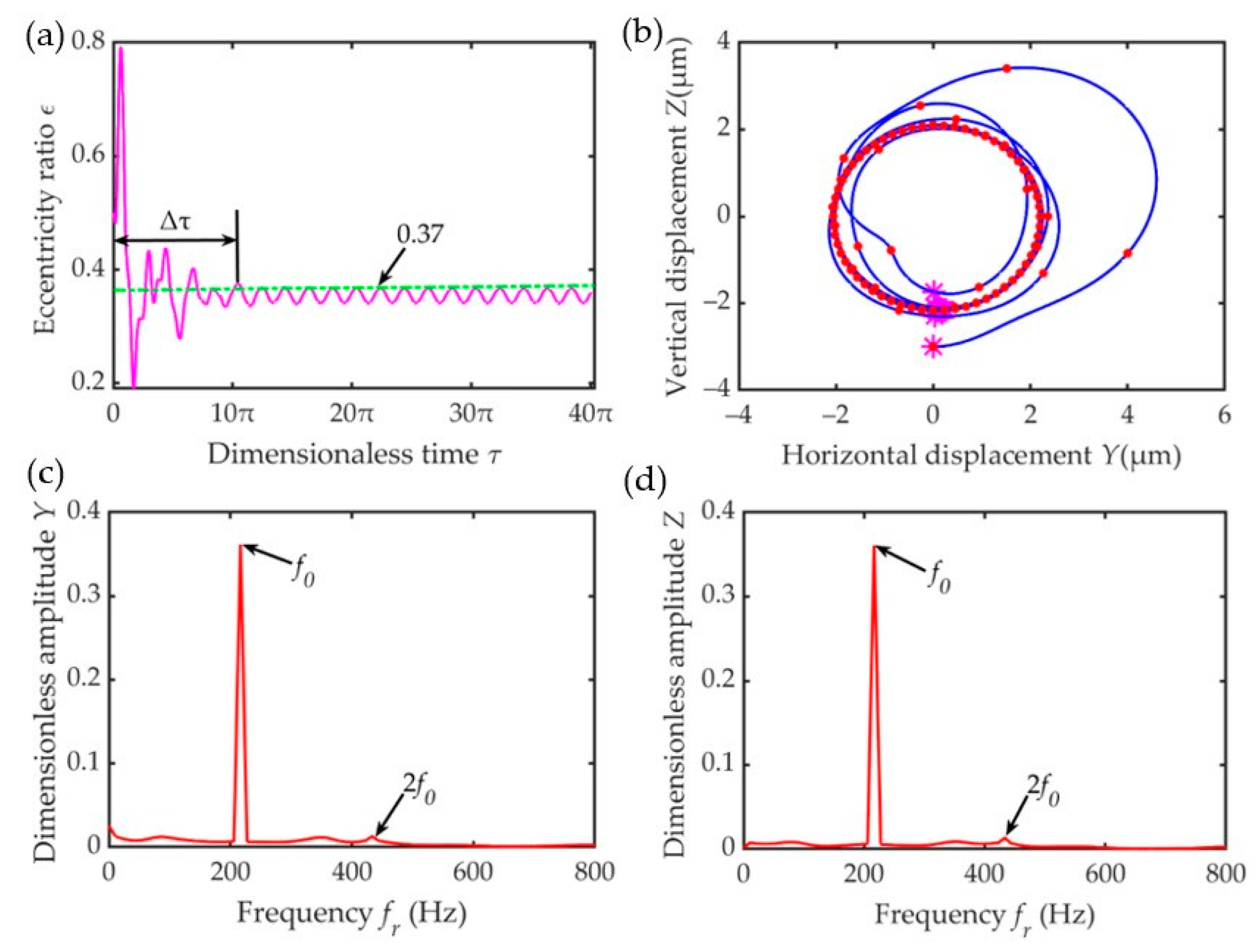
Figure 14 reveals the simulation results with the screw mass at the same speed. Upon comparison and analysis of the test and model simulation data, it can be found that these conclusions are relatively in good agreement. The difference lies in the fact that the spectrum of displacement in the Y-direction and Z-direction is primarily dominated by the fundamental frequency and its corresponding frequency doubling.
In general, due to the complexity of rigid-elastic-liquid coupled ball bearings, which greatly increases the difficulty of accurate quantitative analysis, it can only be qualitatively analyzed and compared with the simulation results to verify the rationality of the test results and the established model. In addition, the testing machine has assembly errors, test errors, environmental interference, and other factors, and it also needs professional technical personnel to assist with the operation, making data acquisition a hard-won endeavor.

6. Conclusions

In this study, a dynamic model of a rotor–ERSFD–ball bearing structure was established, and the dynamic response of the outer ring of the ball bearing under sudden unbalance was simulated and analyzed. The steady-state amplitude, transient response time history, transmissibility, motion trajectory, and displacement spectrum characteristics were analyzed with the speed, damping, and mass ratios as the analysis parameters affecting the outer ring. By measuring the center locus of the bearing outer ring under two unbalanced conditions, the rationality of the model could be verified. The main results and conclusions are as follows:
(1)
Under a constant unbalance, the lower the speed ratio, the lower the damping ratio, and the higher the mass ratio, the shorter the transient response time when entering the steady state. At a low-speed ratio, high damping ratio, and low mass ratio, the steady-state amplitude is small, making it more conducive to suppressing the bearing vibration. With an increase in unbalance, the eccentricity, transmissibility, displacement amplitude of the amplitude–frequency response, and the radius of the outer ring center locus increased.
(2)
The ERSFD and the ball bearing are coupled to each other. In this case, the sensitivity of the relevant parameters to the oil film force, from high to low, followed the order: speed ratio, damping ratio, and mass ratio.
(3)
Due to the existence of various frequency components, such as the fundamental frequency, frequency doubling, and subharmonics, the motion state of the bearing outer ring was found to be more complex in the transient response stage.

Author Contributions

Conceptualization, Y.L.; methodology, Y.L.; software, Y.L.; validation, Y.L.; formal analysis, Y.L.; investigation, Y.L.; resources, S.D. and Y.C.; data curation, Y.L.; writing—original draft preparation, Y.L. and S.D.; writing—review and editing, Y.L., S.D. and Y.C.; visualization, Y.L.; supervision, S.D. All authors have read and agreed to the published version of the manuscript.

Funding

The work described in this paper was supported by the National Science Foundation of China (Grant No. 52005158) and the Innovation Platform Project of Key Laboratory of Power Transmission Technology on Aero Engine, Aero Engine Corporation of China (Grant No. CXPT-2023-020).

Data Availability Statement

Data are contained within the article.

Acknowledgments

The authors must thank Jingjing Wang and Xiaoguo Gao (from the Key Laboratory of Power Transmission Technology on Aero Engine, Aero Engine Corporation of China, Shenyang) for their help in the experimental validation.

Conflicts of Interest

The authors declare no conflicts of interest.

Nomenclature

The following nomenclature is used in this manuscript:
a The mass ratio
β The installation angle of the first inner boss
C 1 The radial clearance of the inner cavity oil film
θ The angle of the start of positive pressure region measured from the center line
θ i The angle between the ith inner boss and the negative direction of the Z axis
C d The external damping coefficient
C c The critical damping coefficient
e b The eccentricity between the bearing center and the center of the journal
e d The eccentricity between the bearing center and the center of the disc
ε d The disc eccentricity
ε b The journal eccentricity
φ b The attitude angle of the journal
F r The radial oil film force
F t The circumferential oil film force
F d r The radial component of the elastic force acting on the journal
F d t The tangential component of the elastic force acting on the journal
F s r The radial component of the elastic force acting on the disc
F s t The tangential component of the elastic force acting on the disc
F a r The radial component of the external damping force acting on the disc
F a t The tangential component of the external damping force acting on the disc
F u The unbalanced force concentrated on the disc
ϕ m The difference between the position angle of the ith boss force and the position angle of the radial deflection point on the elastic ring
F E R S F D The squeeze oil film force
F c s The center spring force
G b The gravity of the journal
G d The gravity of the disc
Γ The flexibility coefficient of the elastic ring
h i The thickness of the oil film in the inner cavity
k e r The elastic ring stiffness
K y The squirrel cage stiffness in the Y-axis direction
K z The squirrel cage stiffness in the Z-axis direction
K s The stiffness of the shaft
k e The deformation amount of the elastic ring
k s c The stiffness of the squirrel cage
L b The length of the damper
λ The speed ratio
m b The vibration mass concentrated at the journal
m d The vibration mass at the disc
μ The dynamic viscosity of the oil
N The number of the inner bosses
O b The bearing center
O j The center of the journal
O 1 The center of the disc
ω The angular velocity of the journal
ω c The critical angular velocity of the rotor system
q i The force applied to the inner boss
R The radius of the journal
r The radial squeeze direction
t The direction of circumferential orbital motion
T i The support reaction at the boss of the elastic ring
T Transmissibility
U t The sudden unbalance
x The axial coordinate
y , z Represent the offset distance of the journal in the Y-axis and Z-axis, respectively
ζ The damping ratio

References

  1. Liu, P.; Wang, L.; Ma, F.; Zhang, D.; Wu, J.; Li, Z. Influence of assembly clearance on vibration characteristics of angular contact ball bearings in the thermal environment. Tribol. Int. 2023, 181, 108317. [Google Scholar] [CrossRef]
  2. Lu, H.; Li, W.; Shen, J.; Chen, T.; Sheng, L. Dynamic Characteristics Analysis of Rotor-Bearing System Considering Bearing Clearance and Hybrid Eccentricity. J. Vib. Eng. Technol. 2024, 12, 2249–2263. [Google Scholar] [CrossRef]
  3. Zhang, Z.Y. Bifurcations and Hysteresis of Varying Compliance Vibrations of a Ball Bearing-Rotor System; Harbin Institute of Technology: Harbin, China, 2015. [Google Scholar]
  4. Deng, S.; Fu, J.; Wang, Y.; Yang, H. Analysis on dynamic characteristics of aero-engine rolling bearing/dual-rotor system. J. Aerosp. Power 2013, 28, 195–204. [Google Scholar]
  5. Deng, S.; He, F.; Yang, H.; Li, Y. Analysis on dynamic characteristics of a dual rotor-rolling bearing coupling system for aero-engine. J. Aerosp. Power 2010, 25, 2386–2395. [Google Scholar]
  6. Cao, H.; Niu, L.; Xi, S.; Chen, X. Mechanical model development of rolling bearing-rotor systems: A review. Mech. Syst. Signal Process. 2018, 102, 37–58. [Google Scholar] [CrossRef]
  7. Chen, S.; Shuai, Q.; Chen, X.; Gu, J.; Liu, Z. Influence of rotor unbalance on dynamic coupling characteristics of angular contact ball bearing-rigid rotor system. J. Aerosp. Power 2021, 36, 2126–2138. [Google Scholar]
  8. Hamzehlouia, S.; Behdinan, K. Squeeze film dampers supporting high-speed rotors: Rotor dynamics. Proc. Imech E Part J J. Eng. Tribol. 2021, 235, 495–508. [Google Scholar] [CrossRef]
  9. Oliveira, M.; Daniel, G.B. Vibrational signature of journal bearing oil starvation considering thermal effects and rotor unbalance variation. Tribol. Int. 2024, 191, 109132. [Google Scholar] [CrossRef]
  10. Zhang, S.; Xu, H.; Zhang, L.; Xing, Y.; Guo, Y. Vibration suppression mechanism research of adjustable elliptical journal bearing under synchronous unbalance load. Tribol. Int. 2019, 132, 185–198. [Google Scholar] [CrossRef]
  11. Li, T.; Ren, X.; Yue, C. Transient response of single-disc rotor system under sudden unbalance load. Mech. Sci. Tech. Aerosp. Eng. 2012, 6, 924–927. [Google Scholar]
  12. Sun, G.; Palazzolo, A.; Provenza, A.; Lawrence, C.; Carney, K. Long duration blade loss simulations including thermal growths for dual-rotor gas turbine engine. J. Sound Vib. 2008, 316, 147–163. [Google Scholar] [CrossRef]
  13. Zhao, L.; Liao, M.; Hong, L.; Lei, X.; Li, M.; Wang, S.; Hou, L.; Shao, Z. Analysis of aero-engine vibration response under sudden unbalance. J. Aerosp. Power 2022, 37, 251–262. [Google Scholar]
  14. Zhao, L.; Liao, M.; Niu, J. Investigation on Steady State Unbalance Response of Rotor with Elastic Ring Squeeze Film Damper. IOP Conf. Ser. Mater. Sci. Eng. 2020, 751, 012043. [Google Scholar] [CrossRef]
  15. Zhu, C.; Feng, X. Experimental study of nonsynchronous orbits in a flexible rotor-squeeze film damper system. J. Aerosp. Power 1987, 04, 323–327. [Google Scholar]
  16. Zhu, C.; Feng, X.; Xu, J. The behavior of main resonant bistable operation in nonlinear squeeze film damper-flexible rotor systems. J. Vib. Eng. 1989, 1, 5. [Google Scholar]
  17. Li, Q.; Zhao, F.; Zhang, S. Experimental investigation on blade loss transient response of rotor with flexible damped support. J. Aerosp. Power 1992, 7, 103–107. [Google Scholar]
  18. Meng, G.; Xue, Z.; Zhu, C.; Feng, X. Investigation on the non-synchronous responses of flexible rotor-uncentralized squeeze film damper bearings system. J. Aerosp. Power 1987, 02, 121–125. [Google Scholar]
  19. Dong, H.; Zhang, A.; Shu, H.; Zhang, C. Simultaneous identification method of rotor distributed unbalance and bearing char-acteristic parameters. J. Harbin Inst. Technol. 2022, 54, 128–135. [Google Scholar]
  20. He, W.; Pan, B.; Bai, J. Transient response analysis of squeezed film damper rotor system under sudden unbalance load. Gas. Turbine. Exp. Res. 2020, 33, 36–40. [Google Scholar]
  21. Yao, W. Study on Simultaneous Identification of Rotor Unbalance and Bearing Coefficients of a Rotor. Ph.D. Thesis, China University of Mining and Technology, Xuzhou, China, 2019. [Google Scholar]
  22. Ou, X.; Zhang, Y.; Zhang, K.; Wang, Y. Dynamic model of deep groove bearing considering unbalanced force and disturbing force. Mach. Des. Manuf. 2022, 12, 6–10. [Google Scholar]
  23. Zhu, C.; Robb, D.A.; Ewins, D.J. Analysis of the multiple-solution response of a flexible rotor supported on non-linear squeeze film damper. J. Sound Vib. 2002, 252, 389–408. [Google Scholar] [CrossRef]
  24. Inayat-Hussain, J.I. Bifurcations in the response of a flexible rotor in squeeze-film dampers with retainer springs. Chaos Solitons Fractals 2009, 39, 519–532. [Google Scholar] [CrossRef]
  25. Zhang, J.; Xu, Q.; Zheng, T. The stability and bifurcation of a squeeze film damper-sliding bearing-rigid rotor system. Chin. J. Appl. Mech. 1996, 13, 35–40. [Google Scholar]
  26. Gjika, K.; San Andrés, L.; Larue, G.D. Nonlinear dynamic behavior of turbo charger rotor-bearing systems with hydrodynamic oil film and squeeze film damper in series: Prediction and experiment. J. Comput. Nonlinear Dyn. 2010, 5, 041006. [Google Scholar] [CrossRef]
  27. Xu, M.; Liao, M. The vibration performance of the Jeffcott rotor system with SFD in maneuver flight. J. Aerosp. Power 2003, 18, 8. [Google Scholar]
  28. Meng, G. Sudden unbalance responses of flexible rotor supported in squeeze film dampers. Chin. J. Appl. Mech. 1993, 22, 10–16. [Google Scholar]
  29. Heidari, H.; Ashkooh, M. The influence of asymmetry in centralizing spring of squeeze film damper on stability and bifurca-tion of rigid rotor response. Alex. Eng. J. 2016, 55, 3321–3330. [Google Scholar] [CrossRef]
  30. Chen, H.; Hou, L.; Chen, Y. Bifurcation analysis of a rigid- rotor squeeze film damper system with unsymmetrical stiffness supports. Arch. Appl. Mech. 2017, 87, 1347–1364. [Google Scholar] [CrossRef]
  31. Chen, X.; Gan, X.; Ren, G. Dynamic modeling and nonlinear analysis of a rotor system supported by squeeze film damper with variable static eccentricity under aircraft turning maneuver. J. Sound Vib. 2017, 485, 11551. [Google Scholar] [CrossRef]
  32. Zhou, C. Research on the Dynamic Behavior of a Rotor System Supported by Rolling Bearing with Squeeze Film Damper. Master’s Thesis, Shanghai University, Shanghai, China, 2019. [Google Scholar]
  33. Yang, Z.D. Study on Response Characteristics and Stability of Rotor System under Sudden High Energy Excitation Load. Master’s Thesis, Nanjing University of Aeronautics and Astronautics, Nanjing, China, 2020. [Google Scholar]
  34. Pan, B. Study on Sudden Unbalance Response of Rotor System with Squeeze Film Damper. Master’s Thesis, Civil Aviation University of China, Tianjin, China, 2019. [Google Scholar]
  35. Jiang, Y.; Bin, G.; Li, C.; Li, J. Study on unbalance phase difference combined vibration response of turboshaft engine combustor rotor considering dynamic characteristics of flexible supports. Mech. Sci. Tech. Aerosp. Eng. 2022, 41, 1524–1529. [Google Scholar]
  36. Molčan, M.; Ferfecki, P.; Zapoměl, J. The numerical identification of basins of attraction for the vibration response of the rigid rotor with squeeze film dampers. Appl. Sci. 2023, 13, 2864. [Google Scholar] [CrossRef]
  37. Ri, K.; Ri, Y.; Yun, C.; Kim, K.; Han, P. Analysis of nonlinear vibration and stability of Jeffcott rotor supported on squeeze-film damper by IHB method. AIP Adv. 2022, 12, 025127. [Google Scholar]
  38. Ye, D. Research of Dynamic Response on High Speed Flexible Rotor Due to Sudden Large Unbalance. Master’s Thesis, Zhejiang University, Hangzhou, China, 2014. [Google Scholar]
  39. Han, Z.; Ma, Z.; Zhang, W.; Han, B.; Ding, Q. Dynamic analysis of an elastic ring squeeze film damper supported rotor using a semi-analytic method. Eng. Appl. Comp. Fluid Mech. 2020, 14, 1263–1278. [Google Scholar] [CrossRef]
  40. Zhou, H.; Luo, G.; Ai, Y.; Sun, D. Sudden unbalance response analysis of rotor system supported on floating ring squeeze film damper. J. Aerosp. Power 2014, 29, 7. [Google Scholar]
  41. Zhou, H.; Luo, G.; Chen, G.; Wang, F. Analysis of the nonlinear dynamic response of a rotor supported on ball bearings with floating-ring squeeze film dampers. Mech. Mach. Theory 2013, 59, 65–77. [Google Scholar] [CrossRef]
  42. Xia, Y.; Ren, X.; Qin, W.; Deng, W. Analysis of the effect of floating ring squeeze film damper on sudden unbalance response of low pressure rotor. J. Aerosp. Power 2015, 30, 2771–2778. [Google Scholar]
  43. Zhang, G.; Huang, Y.; Chen, Y.; Wang, Z.; Xu, K.; Feng, L. Experiment on vibration reduction performance of elastic ring squeeze film damper under sudden unbalance. J. Aerosp. Power 2023, 38, 32–40. [Google Scholar]
  44. Yang, X.; Jiang, B.; Li, Y.; Zhao, Q.; Deng, S.; Zhang, W.; Cui, Y. Dynamic characteristics of elastic ring squeeze film damper coupled high-speed ball bearings. J. Sound Vib. 2022, 537, 117186. [Google Scholar] [CrossRef]
  45. Li, Y.; Yang, H.; Cui, Y.; Deng, S.; Zhang, W. Nonlinear dynamic properties of rigid-elastic-liquid coupled ball bearings considering external load excitation. Int. J. Struct. Stab. Dy. 2024; in press. [Google Scholar]
  46. Zhong, X.; Jiang, J.; Bin, G.; Chen, A.; Yang, F. Vibration characteristics of turbocharger rotor system considering internal thread texture parameters of semi-floating ring bearing. Proc. IMechE Part J J. Eng. Tribol. 2023, 237, 1796–1808. [Google Scholar] [CrossRef]
  47. Deng, S.; Jia, Q.; Xue, J. Rolling Bearing Design Principle, 2nd ed.; Standards Press of China: Beijing, China, 2014. [Google Scholar]
  48. Liu, J.; Chiu, Y. Analysis of a thin elastic ring under arbitrary loading. J. Eng. Ind. 1974, 96, 870. [Google Scholar] [CrossRef]
  49. Greenhill, L.M.; Nelson, H.D. Iterative determination of squeeze film damper eccentricity for flexible rotor systems. J. Mech. Des. 1982, 104, 334–338. [Google Scholar] [CrossRef]
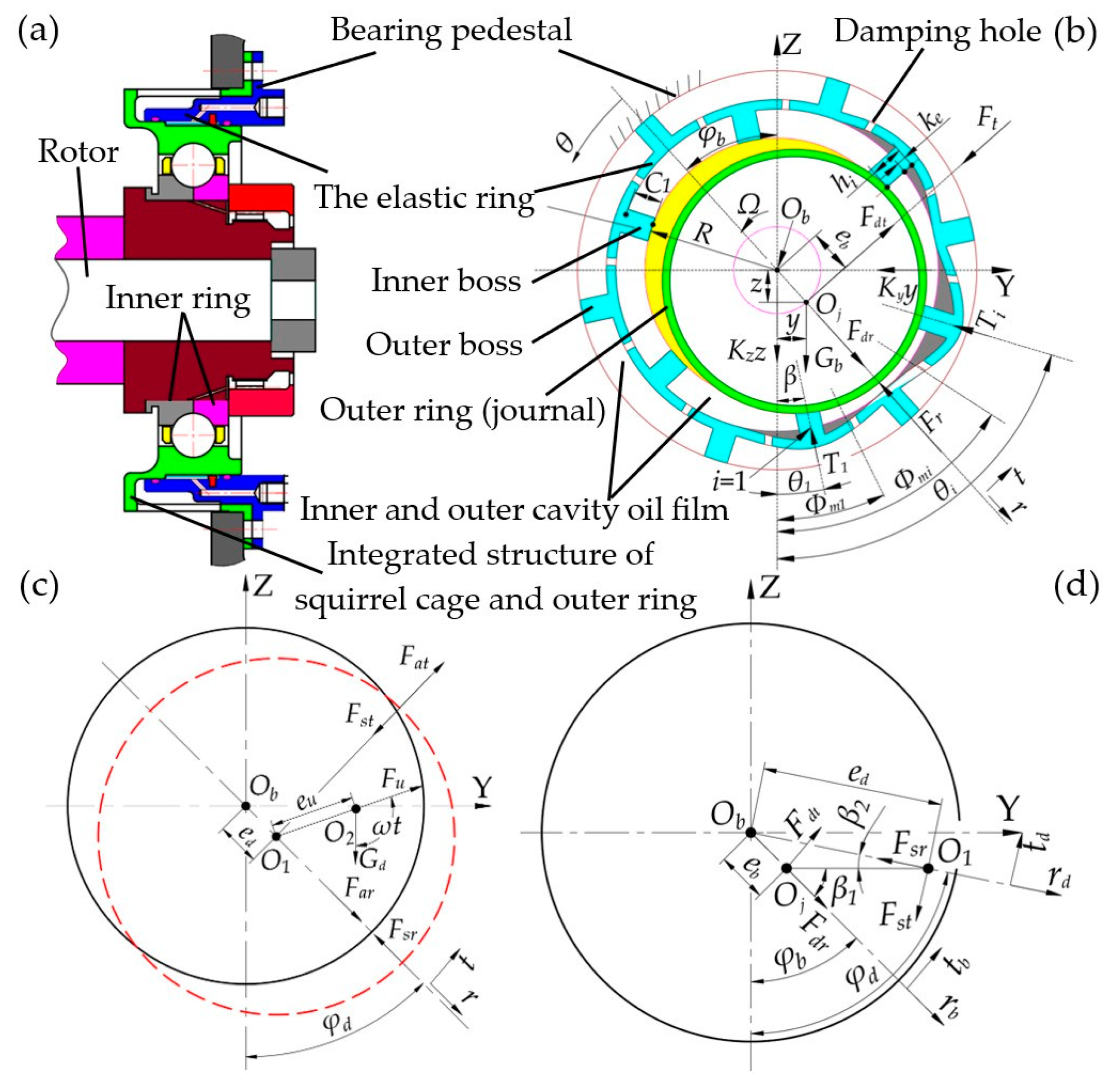
Figure 1. Schematic of the dynamic model: (a) rotor–ERSFD–bearing structure; (b) force diagram of the damper journal; (c) force diagram of the disc; (d) elastic force relation diagram of the journal and disc.
Lubricants 12 00161 g001
Figure 2. Model solving flowchart.
Lubricants 12 00161 g002
Figure 3. Influence degree of each parameter on the oil film force.
Lubricants 12 00161 g003
Figure 4. Influence of speed ratio on dynamic characteristics of the outer ring with U t = 0.4 : (a) time-varying displacement; (b) transmissibility; (c) outer ring center locus ( λ = 0.72 ); (d) outer ring center locus ( λ = 1.29 ); (e) spectrum of displacement Y; (f) spectrum of displacement Z. * represents the Poincaré map.
Lubricants 12 00161 g004
Figure 5. Influence of speed ratio on dynamic characteristics of the outer ring with U t = 0.6 : (a) time-varying displacement; (b) transmissibility; (c) outer ring center locus ( λ = 0.72 ); (d) outer ring center locus ( λ = 1.29 ); (e) spectrum of displacement Y; (f) spectrum of displacement Z. (* represents the Poincaré map).
Lubricants 12 00161 g005
Figure 6. Influence of damping ratio on dynamic characteristics of the outer ring with U t = 0.4 : (a) time-varying displacement; (b) transmissibility; (c) outer ring center locus ( ζ = 0.5 ); (d) outer ring center locus ( ζ = 1.6 ); (e) spectrum of displacement Y; (f) spectrum of displacement Z. (* represents the Poincaré map).
Lubricants 12 00161 g006
Figure 7. Influence of damping ratio on dynamic characteristics of the outer ring with U t = 0.6 : (a) time-varying displacement; (b) transmissibility; (c) outer ring center locus ( ζ = 0.5 ); (d) outer ring center locus ( ζ = 1.6 ); (e) spectrum of displacement Y; (f) spectrum of displacement Z. (* represents the Poincaré map).
Lubricants 12 00161 g007
Figure 8. Influence of the mass ratio on the dynamic characteristics of the outer ring with U t = 0.4 : (a) time-varying displacement; (b) transmissibility; (c) outer ring center locus ( a = 0.33 ); (d) outer ring center locus ( a = 0.13 ); (e) spectrum of displacement Y; (f) spectrum of displacement Z. (* represents the Poincaré map).
Lubricants 12 00161 g008
Figure 9. Influence of the mass ratio on the dynamic characteristics of the outer ring with U t = 0.6 : (a) time-varying displacement; (b) transmissibility; (c) outer ring center locus ( a = 0.33 ); (d) outer ring center locus ( a = 0.13 ); (e) spectrum of displacement Y; (f) spectrum of displacement Z. (* represents the Poincaré map).
Lubricants 12 00161 g009
Figure 10. Overall structure of the testing machine.
Lubricants 12 00161 g010
Figure 11. Unbalance simulation and layout of displacement measuring points on the outer ring.
Lubricants 12 00161 g011
Figure 12. Test results without screw at n b = 13,000 r/min: (a) time-varying displacement; (b) outer ring center locus (200 points).
Lubricants 12 00161 g012
Figure 13. Test results with the screw mass of 4 g at n b = 13,000 r/min: (a) time-varying displacement; (b) outer ring center locus (200 points); (c) spectrum of displacement Y; (d) spectrum of displacement Z.
Lubricants 12 00161 g013
Figure 14. Simulation results with the screw mass of 4 g at n b = 13,000 r/min: (a) time-varying displacement; (b) outer ring center locus; (c) spectrum of displacement Y; (d) spectrum of displacement Z. (* represents the Poincaré map).
Lubricants 12 00161 g014
Table 1. Parameters related to the model.
SymbolValue or Range Variation
Equivalent mass of the damper m b   kg 19.8
The vibration mass range at the disc m d   kg 57.6 180
The stiffness of the shaft K s   N / m 1 × 10 8
The stiffness [45] of the squirrel cage k s c   N / m 1.825 × 10 7
The length of the Damper L   mm 30
Inner cavity oil film radius clearance C 1 mm 0.6
The radius of the journal R   mm 107.85
The journal angular velocity range ω   rad / s 732.67 1884
The critical angular velocity of the rotor system ω c   rad / s 1300
The damping ratio range ζ 0.4 2.0
The oil type 4106
Dynamic viscosity of the oil μ   Pa . s 5.5 × 10 2
The stiffness [45] of the elastic ring k e r   N / m 7.85 × 10 6
The flexibility coefficient [45] of the elastic ring Γ   m / N 0.1
The number of the boss N 20
Table 2. Related parameters of the dynamic characteristics of a structure coupled with the ERSFD and ball bearing under sudden unbalance.
Run C 1   mm m b   kg ω c   rad / s ω s λ ζ a
U t = 0.4 0.615.613000.70550.72, 1.2910.25
U t = 0.6
U t = 0.4 0.615.613000.70550.970.5, 1.60.25
U t = 0.6
U t = 0.4 0.615.613000.70550.9710.33, 0.13
U t = 0.6
Disclaimer/Publisher’s Note: The statements, opinions and data contained in all publications are solely those of the individual author(s) and contributor(s) and not of MDPI and/or the editor(s). MDPI and/or the editor(s) disclaim responsibility for any injury to people or property resulting from any ideas, methods, instructions or products referred to in the content.