Article

Effect of Acoustic Emission Sensor Location on the Detection of Grinding Wheel Deterioration in Cylindrical Grinding

1
Department of Mechanical Engineering, University of Fukui, 3-9-1 Bunkyo, Fukui 910-8507, Japan
2
National Institute of Advanced Industrial Science and Technology, 1-2-1 Namiki, Tsukuba 305-8564, Japan
3
JTEKT Corporation, 1-1 Asahi-machi, Kariya 448-8652, Japan
*
Author to whom correspondence should be addressed.
Lubricants 2024, 12(3), 100; https://doi.org/10.3390/lubricants12030100
Submission received: 20 December 2023 / Revised: 15 February 2024 / Accepted: 20 February 2024 / Published: 18 March 2024
(This article belongs to the Special Issue Acoustic Emission Techniques in Wear Monitoring II)

Abstract

:
The acoustic emission (AE) technique is an effective method for monitoring grinding wheels, and numerous studies have been published on applying an AE to monitor grinding wheels. However, there are few studies on the effect of the location of the AE sensor in stably acquiring the AE signals generated during deterioration in cylindrical grinding wheels. In this study, we propose a stable method for detecting the deterioration of a cubic boron nitride (cBN) grinding wheel during cylindrical grinding using AE. We compared the AE signals acquired during grinding from an AE sensor located on the hydrostatic bearing, which supports the grinding wheel shaft, with those from the tailstock spindle. Although positioning the AE sensor on the hydrostatic bearing was found to reduce the AE signal intensity, the AE signal variations were smaller at the same grinding position, and the effect of the grinding position was less than that for the tailstock spindle. Moreover, positioning an AE sensor on the hydrostatic bearing is considered to provide the characteristics of AE signals specifically focused on the changes in cBN on the grinding wheel surface allowing the surface roughness of the workpiece to be estimated during grinding.

1. Introduction

Grinding is a prevalent material removal process used in various industrial sectors, including the aerospace and the automotive industry. The advantages of grinding in precision machining over other material removal processes such as turning and milling include better surface finishes and longer production runs [1]. However, grinding is a complex machining process because the topography of the wheel surface undergoes continuous changes as a result of the interaction with the work surface, which directly impacts the quality of the resultant work surface [2]. Therefore, it is imperative to establish an effective monitoring method based on understanding the changes that occur on the wheel surface to monitor grinding wheels. The methods for monitoring grinding wheels can be divided into two categories: direct and indirect methods. Direct methods measure the wheel surface topography using a replication method [3,4], scanning electron microscopy (SEM) [5,6], or an imaging sensor [7,8]. However, these methods require the stopping of operations and are difficult to apply under lubrication. In contrast, indirect methods, which are based on sensors such as force, power, vibration, and acoustic emission (AE) sensors, allow for the monitoring of grinding wheels without the need to stop operations. Accordingly, numerous studies on monitoring techniques for grinding wheels that employ indirect methods have been published.
This study focuses on an indirect method that uses an AE sensor to monitor a grinding wheel. A grinding wheel undergoes continuous wear during its operation owing to attrition, grain fracture, and bond fracture. AE is a phenomenon in which elastic waves are generated by the rapid release of local energy during the deformation and fracture of materials. The primary sources of AE during grinding include elastic impact, bond fracture, grain fracture, friction, and indentation cracks [9]. Thus, AE is a suitable and effective phenomenon for monitoring grinding wheels, as it contains valuable information about the micro-phenomena associated with the grinding process and wheel wear. A review of the methods that use AE for monitoring grinding wheel deterioration is given below.
Hundt et al. reported that different phenomena in grinding wheel wear can be readily distinguished by their individual AE signatures at different frequencies in single-grain experiments [9]. Haussi et al. [10] reported that the end of a wheel’s life can be determined based on wheel wear using vibration and AE. Liao et al. [11] presented a wavelet-based methodology based on AE signals for monitoring grinding wheel conditions and indicated that the proposed methodology, which involved the use of the genetic clustering algorithm, can estimate the sharp and dull states of grinding wheels with high accuracy. Methods for monitoring grinding wheels that extract features from AE using machine learning have been actively studied. For example, Liao [12] used an ant colony optimization-based method and a sequential forward floating selecting method as a feature selection method, and five classification algorithms—nearest mean (NM), k-nearest neighbor (KNN), fuzzy k-nearest neighbor (FKNN), center-based nearest neighbor (CBNN), and k-means-based nearest prototype (KMNP)—as classifiers. Among all five classifiers, CBNN exhibited the lowest classification error using the wavelet energy feature and AR coefficient dataset. Yang et al. [13] utilized features obtained from the discrete wavelet transformation of AE signals to perform the classification of sharp and worn wheel states using a support vector machine. The classification accuracy was 99.39% under a cutting depth of 10 μm and 100% under a cutting depth of 20 μm. Arul et al. [14] applied a decision tree, artificial neural network, and support vector machine algorithms with linear, quadratic, cubic, and Gaussian kernel functions for the classification of good and dull grinding wheel conditions using AE features such as root mean square (RMS), amplitude, count, and average signal level. An SVM algorithm trained with a cubic kernel can predict the good and dull grinding wheel conditions with a classification accuracy of 97.22%. Sachin et al. [15] tried to identify three tool states—sharp–initial, intermediate–sharp, and worn out–dull—using discrete hidden Markov models trained with time domain AE features achieving a prediction accuracy of 90% for each condition. Shen [16] investigated the effects of the bandwidth of an AE sensor, analysis of window lengths, and feature extraction techniques on classification accuracy in the classification of grinding wheel conditions. The results revealed that FFT-based features were the most effective, demonstrating optimal classification performance with minimal signal data points. As mentioned above, various methods involving the use of machine learning to estimate grinding wheel conditions have been extensively studied. However, as demonstrated in the study by Shen, the selection of optimal features significantly impacts classification accuracy. Thus, it is crucial to accurately detect AE signals containing effective features related to the deterioration of grinding wheels.
Regarding the relationship between the grinding wheel conditions and the surface roughness of the workpiece, Webster et al. [17] analyzed raw AE signals during surface grinding with an aluminum oxide wheel and reported that monitoring the AE RMS and normal force is useful since it is capable not only of contact detection and burn detection but also of monitoring wheel conditions and the cross-lay surface roughness. Mokbel and Maksoud [18] compared the AE spectral amplitude of grinding wheels with different bond types, grit sizes, and conditions, represented by wheel/truing speed ratios, along with the surface roughness (Ra) of ground mild steel specimens and reported that the variations in both the AE spectral amplitude and the surface roughness reflected the surface conditions of the wheel. Lee et al. [19] presented a mapping system of a wheel surface based on the RMS of the AE signals when a diamond tool made contact with the wheel and applied it to the monitoring of a precision manufacturing process.
Based on the above reviews, the AE technique is suitable for monitoring the deterioration of grinding wheel conditions and is capable of estimating the surface roughness of a workpiece indirectly. In the field of wear sensing using AE, Hase et al. [20] reported that dual AE sensing, which is a sensing method wherein AE sensors are placed on each of the sliding materials and the AE signals from each material are measured, can identify wear conditions, but there is not enough research on the effect of the location of the AE sensor on the evaluation of grinding wheel conditions and work surface roughness using AE. Therefore, it is essential to investigate the effect of the AE sensor location on the evaluation of grinding wheel conditions. This study aims to realize an effective method for monitoring grinding wheel deterioration using AE that takes into account the influence of AE sensor location.
In this study, a stable detection method involving the use of AE to monitor the deterioration of a cubic boron nitride (cBN) grinding wheel during cylindrical grinding is proposed to address the above issues. cBN wheels are highly abrasive wheels that are widely used for the efficient grinding of various materials, particularly difficult-to-cut materials, owing to their excellent thermal conductivity, heat resistance, and low wear rate [21,22,23]. In this paper, we also investigate the effect of AE sensor location by comparing the AE signals acquired during cylindrical grinding from sensors located on the hydrostatic bearing supporting the grinding wheel shaft and from sensors located on the tailstock spindle.

2. Grinding Experiments

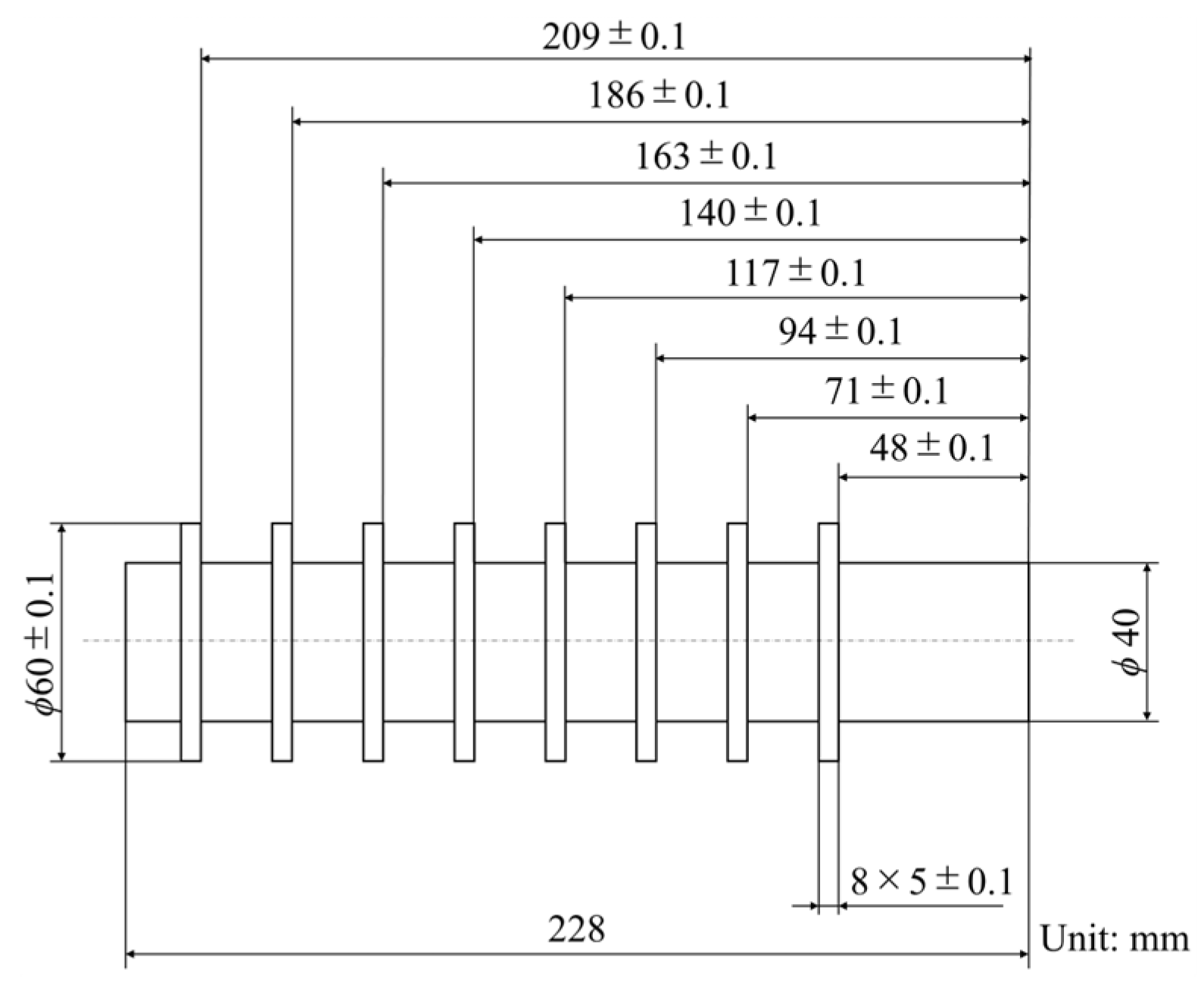
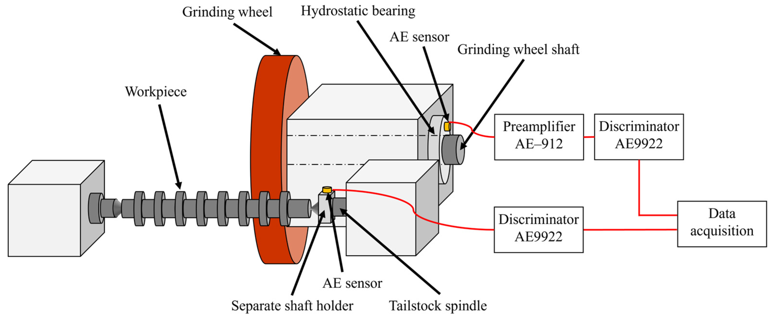
2.1. Experimental Setup

The experimental setup is shown in Figure 1. Cylindrical grinding tests were performed using a GE4Pi CNC cylindrical grinding machine (JTEKT Corporation, Aichi, Japan). The specifications of the cBN wheel used in this study are listed in Table 1. Figure 2 shows a schematic of the workpiece used in the tests. The workpiece had eight grinding portions, each with a diameter of 60 mm, and the internal diameter was 40 mm. The width of each grinding portion was 5 mm. The workpieces were made of JIS SCr420 (similar to AISI 5120) and were carburized and quenched. An FGS700-soluble cutting fluid (Yushiro Chemical Industry Corporation, Tokyo, Japan) was used for the cylindrical grinding tests.
The AE waves generated during grinding were acquired from two AE sensors, one of which was located on a separate shaft holder attached to the tailstock spindle, and the other was located on the hydrostatic bearing supporting the grinding wheel shaft. To reduce the attenuation of the AE waves, a vacuum grease was interposed between the tailstock spindle and the separate shaft holder, and lubricating grease was applied between the workpiece and the tailstock spindle. One AE sensor was attached to the separate shaft holder using thermoplastic adhesive, while the other sensor was adhered to the hydrostatic bearing using instant adhesive. Both sensors were S9225 AE sensors (Physical Acoustics Corporation, NJ, USA; frequency bandwidth: 0.3–1.8 MHz). The AE signal acquired from the AE sensor located on the tailstock spindle was amplified by 60 dB and filtered using a 100 kHz high-pass filter (HPF) using an AE9922 discriminator (NF Corporation, Kanagawa, Japan). The AE signal acquired from the AE sensor located on the hydrostatic bearing was amplified by 40 dB using an AE–912 preamplifier (NF Corporation, Kanagawa, Japan) and then by 20 dB and filtered with the 100 kHz HPF using the AE9922 discriminator. The acquired AE signals were recorded at 5 MS/s using DL850 ScopeCorder (Yokogawa Electric Corporation, Tokyo, Japan), which has 12 bits as the resolution of an analog-to-digital converter. Furthermore, the AE signals from each AE sensor were recorded during the cylindrical grinding tests at the same time.

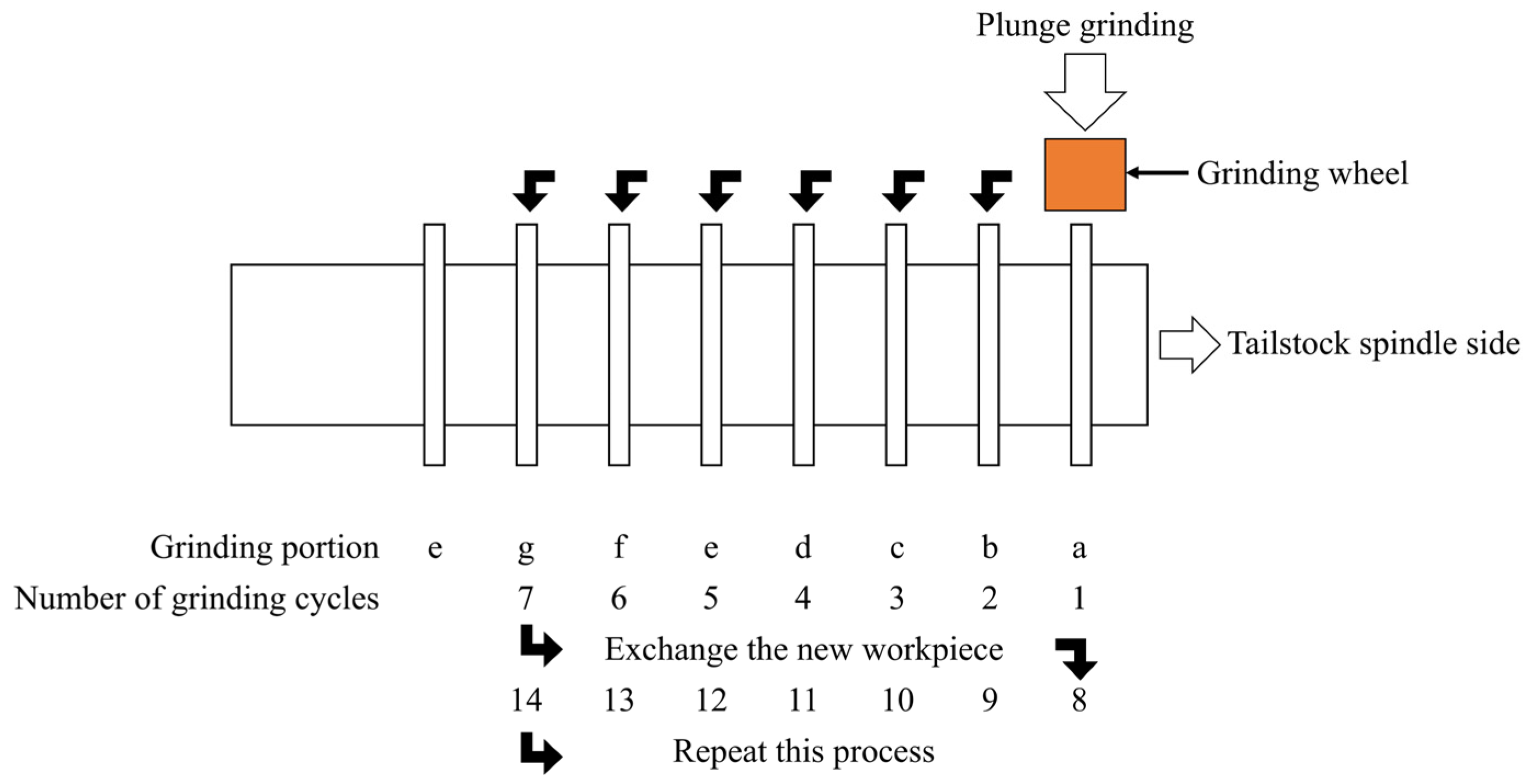
2.2. Experimental Procedure

The experimental conditions for the grinding tests are listed in Table 2. Prior to the grinding tests, the grinding wheel was trued and dressed using a diamond rotary dresser. The dressing and truing were performed at a peripheral velocity ratio between the dresser and the wheel of 0.19, a cutting depth of 1 μm, and a rotary dresser traverse feed of 230 mm/min for 20 cuts. The width of the grinding wheel was 20 mm. An AE signal generated during plunge grinding at the grinding portion of the workpiece was collected. A typical raw AE signal during grinding is shown in Figure 3. The grinding process involved (1) roughing, (2) semi-finishing, (3) finishing, and (4) spark out. Figure 4 shows a schematic of the experimental procedure. The grinding process was conducted in a single grinding portion and the AE signals were acquired during the grinding process at the same time. The grinding tests were performed on one workpiece in an “a” to “g” order and after seven grinding tests were completed, the workpiece was replaced with a new one. This procedure was repeated until the surface roughness Ra of the workpiece reached approximately Ra 0.6 μm. The grinding portion “e” was not used because it interfered with the drive unit of the workpiece and grinding wheel during plunge grinding.

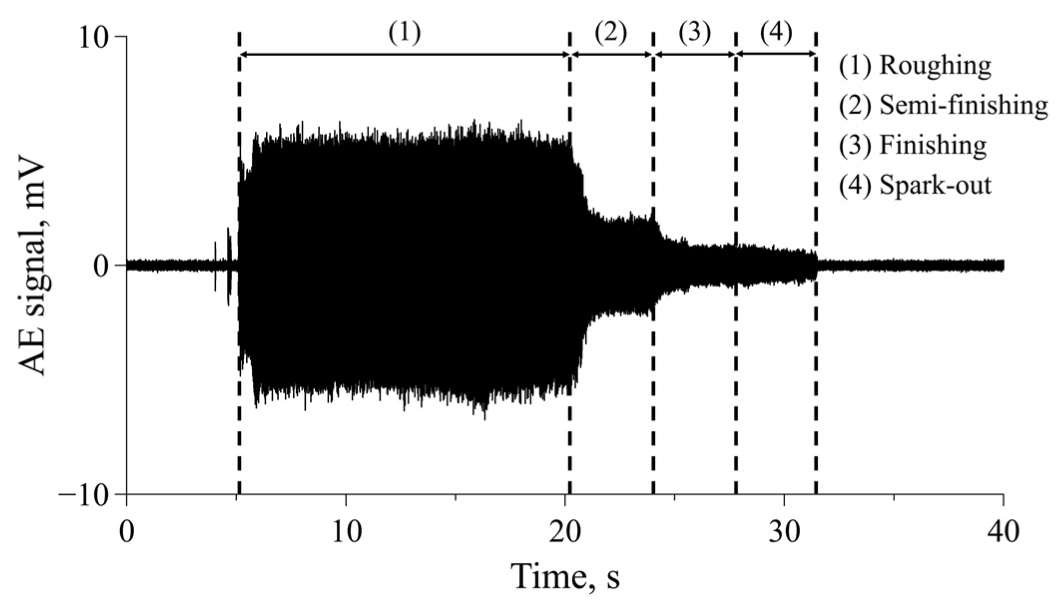
2.3. Signal Analysis for AE Waves

The AE signals acquired from each AE sensor during grinding were analyzed using the RMS value and by performing a fast Fourier transform (FFT). We specifically focused on roughing for RMS value calculation; a 14.9-s AE signal acquired during roughing was segmented into intervals of 0.1 s, and the RMS value was computed for each segmented waveform. The average RMS values for the final 10 s (100 points) of the roughing section were calculated to derive the overall RMS value. The error bars in the figures presented later in this paper depict the range between the maximum and minimum values among the 100 data points. The FFT analysis focused on roughing AE signals, and the raw AE signals during roughing were used for FFT analysis. The window length and window function of the FFT analysis were 1 s and Hanning window, respectively. The data used for the FFT analysis were the central 1 s in the roughing signal of 14.9 s acquired during the grinding process.

3. Experimental Results

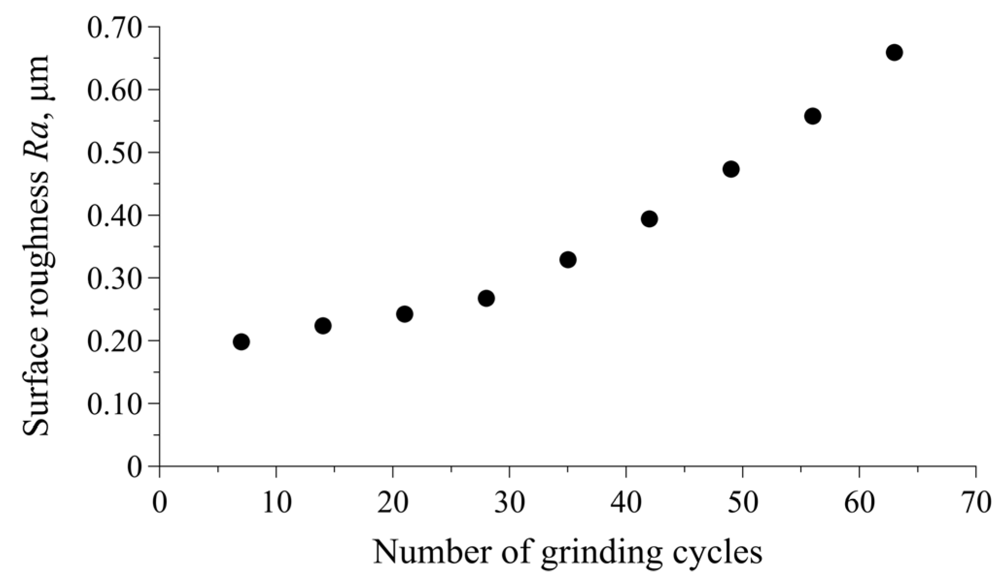
3.1. Surface Roughness Deterioration with an Increasing Number of Grinding Cycles

A graph plotting the surface roughness deterioration of the workpiece against the number of grinding cycles is shown in Figure 5. The surface roughness of the workpiece has an exponential relationship with the number of grinding cycles. The surface roughness of the workpiece increased rapidly with the number of grinding cycles. The grinding experiments continued up to 63 grinding cycles, at which point the surface roughness Ra reached approximately Ra 0.6 μm.

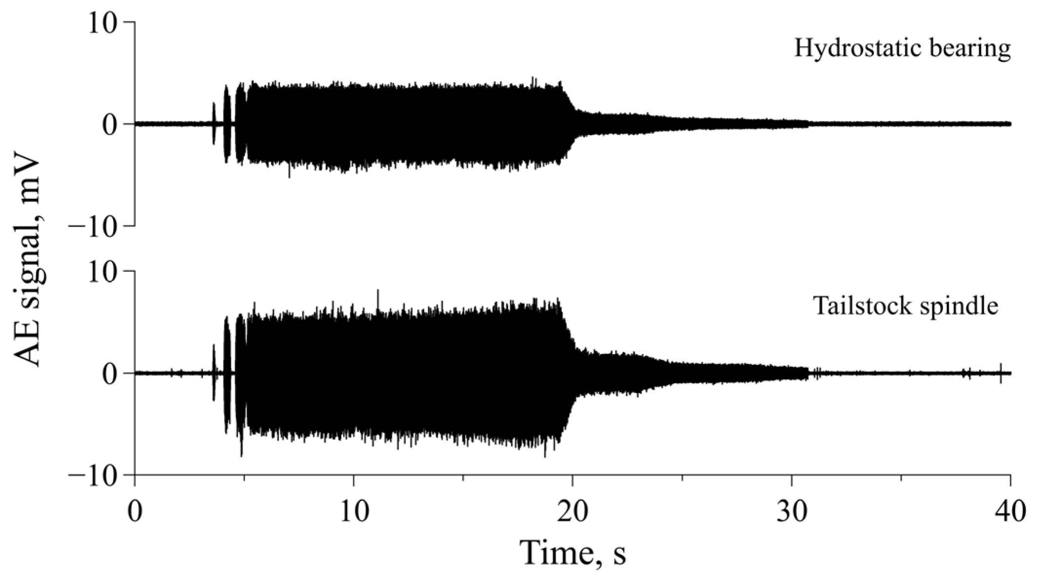
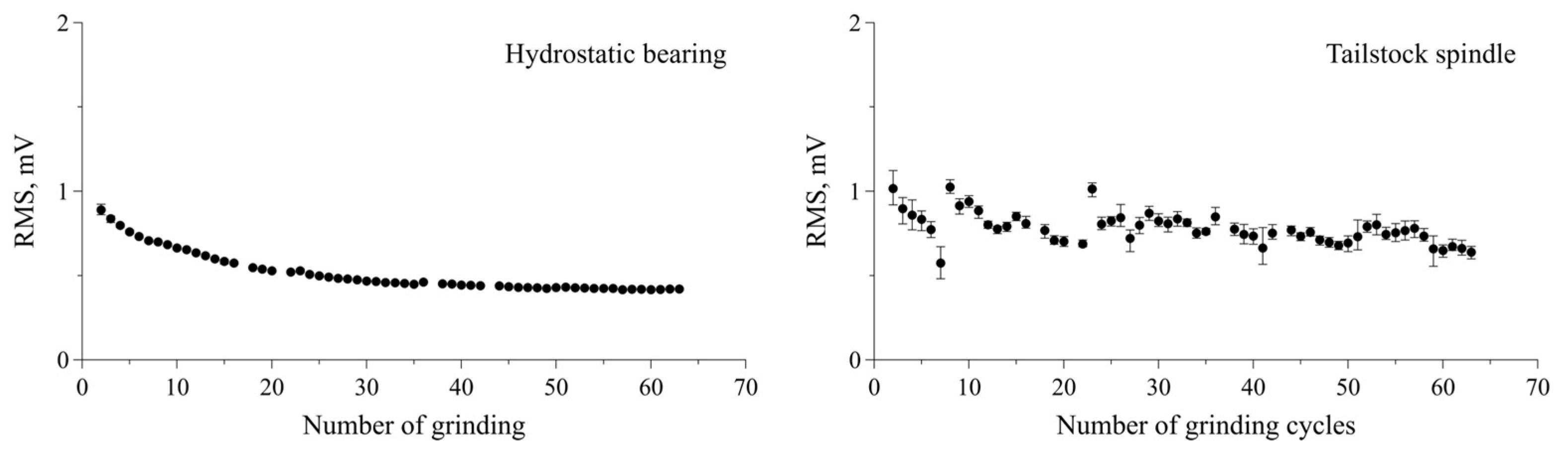
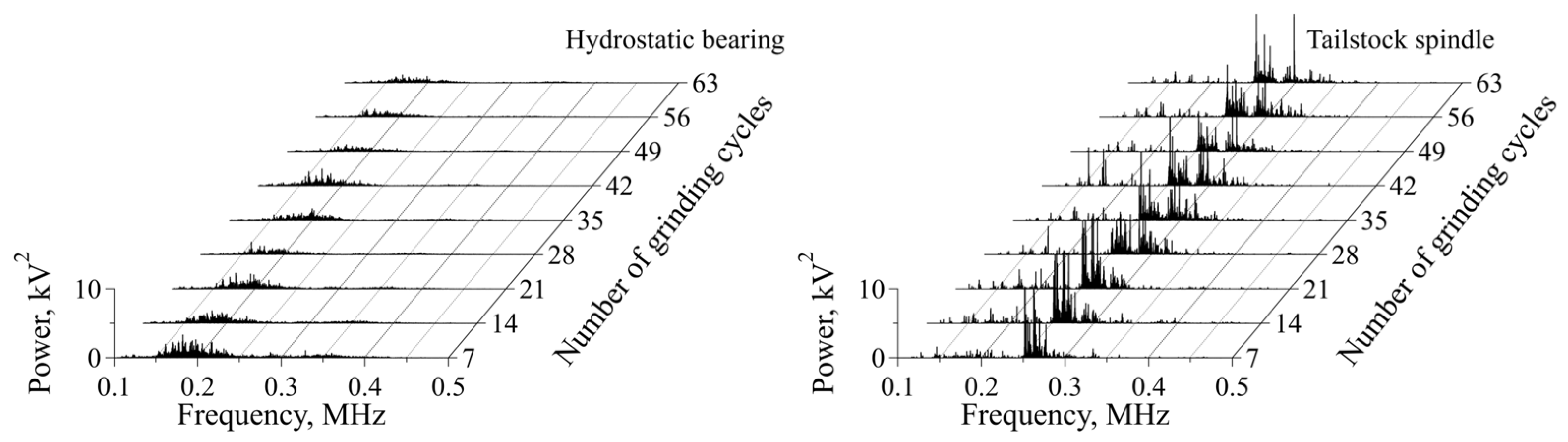
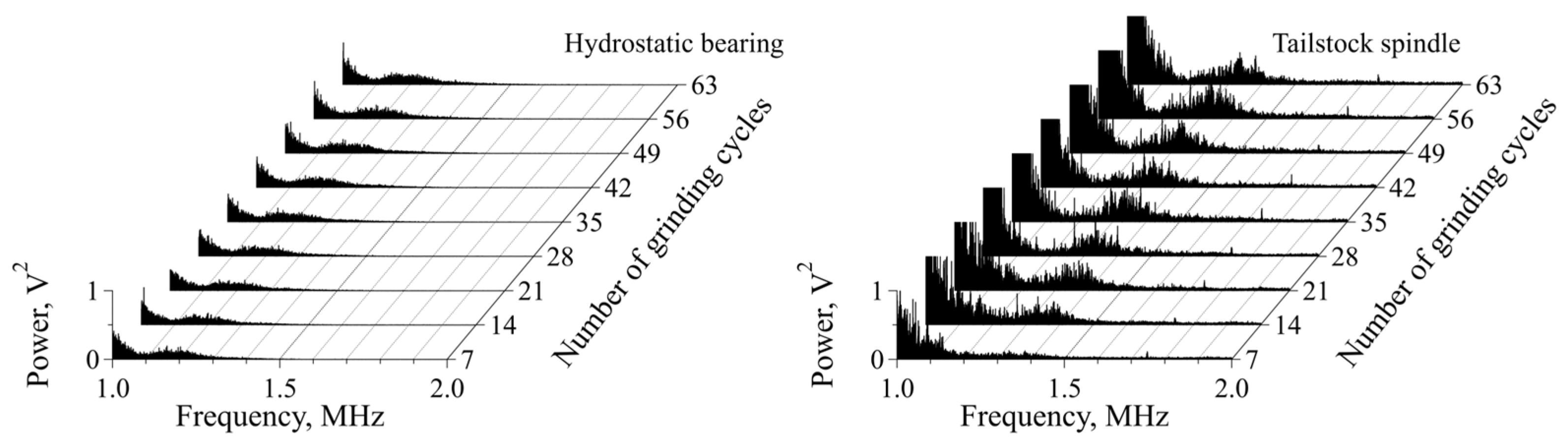
3.2. Analysis of AE Signals Acquired from AE Sensors at Different Locations

The raw AE signals acquired from the AE sensors located at different positions during the grinding tests are shown in Figure 6. The amplitude of the AE signal acquired from the AE sensor located on the hydrostatic bearing supporting the grinding wheel shaft was less than that of the signal acquired from the AE sensor located on the tailstock spindle. Figure 7 shows the RMS values calculated from the roughing AE signals acquired from each AE sensor plotted against the number of grinding cycles. The RMS values of the tailstock spindle decreased with an increase in the number of grinding cycles and exhibited a wide variation for each cycle. In contrast, the RMS values of the hydrostatic bearing, while also decreasing an increase in the number of grinding cycles, exhibited a narrow variation for each cycle. Additionally, the RMS values of the tailstock spindle varied according to the grinding portion of the workpiece, unlike those of the hydrostatic bearing. Hence, it has been demonstrated that stable AE signals that are independent of grinding portions and exhibit narrow variation can be acquired during grinding regardless of the grinding portion by positioning an AE sensor on the hydrostatic bearing supporting the grinding wheel shaft.
Frequency domain analysis can provide additional information regarding the identification of damage and fracture types and has thus been applied for monitoring grinding wheels [11,16,24]. Therefore, we investigated the change in the frequency characteristics of the AE signals acquired from each AE sensor during the grinding cycles. Figure 8 shows FFT spectra, between 0.1 and 0.5 MHz for the roughing AE signals acquired from each AE sensor during grinding plotted against the number of grinding cycles. The FFT spectra for the AE signals acquired from the tailstock spindle have a high spectral intensity at 0.2–0.3 MHz. In contrast, the FFT spectra for the AE signals acquired from the hydrostatic bearing supporting the grinding wheel shaft have a high spectral intensity at 0.1–0.2 MHz. Figure 9 shows the FFT spectra between 1.0 and 2.0 MHz for the roughing AE signals acquired from each AE sensor during grinding plotted against the number of grinding cycles. Distinctive peaks were observed above 1 MHz for the tailstock spindle and the hydrostatic bearing. Notably, for the hydrostatic bearing supporting the grinding wheel shaft, the peaks tended to increase in magnitude with the number of grinding cycles. RMS values calculated from the AE signals filtered with the 1 MHz HPF are shown in Figure 10. The RMS values of the hydrostatic bearing increased with the number of grinding cycles. However, the RMS values of the tailstock spindle exhibited a wide variation for each cycle and did not indicate a clear increasing trend with the number of grinding cycles. Therefore, by mounting an AE sensor on the hydrostatic bearing, it is possible to accurately capture the characteristics of AE signals with frequencies above 1.0 MHz that change with the number of grinding cycles.

4. Discussion

As shown in Figure 7, the RMS values obtained from the AE sensor located on the hydrostatic bearing were smaller than those obtained from the AE sensor located on the tailstock spindle. This difference can be attributed to the attenuation experienced at the various interfaces encountered by the AE signal generated during grinding before it reached the AE sensor located on the hydrostatic bearing. Table 3 shows the number of interfaces that exist before the AE waves generated during grinding reach each AE sensor. The propagation path to the AE sensor located on the hydrostatic bearing has more interfaces than that for the sensor on the tailstock spindle. This difference affected the attenuation of the AE waves, and the AE signal of the sensor placed on the hydrostatic bearing attenuated more rapidly than that of the sensor placed on the tailstock spindle. On the other hand, the AE sensor located on the hydrostatic bearing allowed for a more stable detection of AE signals during grinding than that on the tailstock spindle. This improved stability can be attributed to the consistent propagation path of the AE signal generated during grinding as it reached the AE sensor located on the hydrostatic bearing. In contrast, the AE signal of the tailstock spindle exhibited variations that depended on the grinding portion of the workpiece because of the differing propagation paths to the AE sensor for different grinding positions.
In the frequency domain analysis (Figure 8 and Figure 9), a comparison of the AE sensors located on the hydrostatic bearing and the tailstock spindle showed differences at frequencies below 0.3 MHz. The difference in the number of grinding cycles at frequencies below 0.3 MHz is considered to be due to the AE sensor located on the tailstock spindle detecting AE signals caused by the shear deformation of the workpiece by the cutting of the cBN grain, whereas the AE sensor on the hydrostatic bearing detected AE signals caused by cracks, friction, and fractures of bonds and cBN on the grinding wheel surface. Imai et al. [25] investigated the relationship between an AE signal generated during glass grinding and tribological phenomena. The results indicated that the grinding phenomenon is characterized by the frequency range of 0.1–0.3 MHz in AE signals. Furthermore, AE signals within this frequency range have been confirmed to occur in cutting phenomena as well [26,27]. It is reasonable to infer that this frequency range in AE signals is also present in cutting phenomena, considering that grinding phenomena involve cutting by small abrasive grains. In terms of potential AE sources in cutting processes, Hase et al. suggested that the formation of chips due to workpiece shear deformation, the collision and breakage of chips, and friction between the tool and workpiece or chips are the main causes [28]. On the other hand, it has been suggested that one of the sources of AE signals in grinding are the indentation cracks that appear on the workpiece, induced by abrasive grain [9]. Ramadan et al. reported that the propagation and growth of cracks and failure of steel are characterized by an AE waveform with a peak frequency of 0.20–0.25 MHz [29]. Therefore, the AE signal on the tailstock spindle with a frequency bandwidth of 0.1–0.3 MHz is attributed to a combination of cutting phenomena and cracks.
As an example of the attribution of an AE with a frequency bandwidth above 1.0 MHz, Hase et al. reported that adhesive wear is characterized by an AE waveform with a frequency bandwidth of around 1.1 MHz [30]. Additionally, the AE waves of a hydrostatic bearing can be modulated and attenuated by liquid media such as the lubricating oil present in the hydrostatic bearing. In our previous study on the propagation characteristics of AE waves in liquid media, the attenuation of AE waves propagating in liquid media was small (below 1.5 MHz) [31]. Thus, the AE signals with a frequency bandwidth above 1.0 MHz (Figure 9) in this experiment are attributed to adhesive wear.
As mentioned above, during the grinding of the workpiece, it is inferred that AE waves are generated due to the formation of chips caused by the shear deformation of the workpiece, the collision and breakage of chips, friction between the tool and workpiece or chips, and indentation cracks. When grinding damages the grinding wheel surface, AE waves are generated from the crack, friction, and fractures of bonds and cBN. However, the propagation of these AE waves in the adjacent material is weakened substantially, primarily owing to the pronounced attenuation induced by bubbles in the cutting fluid at the interface between the workpiece and the grinding wheel (see Figure 11a,b). Conversely, in cases of adhesive wear, AE waves are presumed to propagate bidirectionally in both the workpiece and the grinding wheel owing to the adhesive particles (grinding chips) serving as bridges for the AE waves (see Figure 11c). Given these considerations, it is inferred that by positioning the AE sensor on the hydrostatic bearing that supports the grinding wheel spindle, it is possible to detect AE signals specifically associated with the degradation of the grinding wheel surface, which contributes to increased machined surface roughness.
Table 4 provides a summary of the above discussion. Although positioning an AE sensor on the hydrostatic bearing supporting the grinding wheel shaft reduced the intensity of the AE signals, the variations in the AE signals were smaller at the same grinding position, and the effect of the grinding position was less than that for the tailstock spindle. Moreover, positioning an AE sensor on the hydrostatic bearing is considered to provide the characteristics of AE signals specifically focused on the crack, friction, and fractures of bonds and cBN on the grinding wheel surface, and allowing for the surface roughness of the workpiece to be estimated during grinding. Therefore, to realize an effective method for monitoring grinding wheel deterioration using AE, the location of the AE sensor is an important factor, and placing the sensor on the hydrostatic bearing is effective for acquiring an AE signal. Owing to the varied geometries of the workpieces used in cylindrical grinding, the development of intelligent condition monitoring technology for detecting grinding wheel deterioration based on AE requires the robust acquisition of AE signals in any geometrics of workpieces. Despite the limited diversity in the grinding conditions and specifications of the cBN wheels used in the present study, this technique could serve as a robust technique for the acquisition of AE waves generated during grinding and contribute to the future development of intelligent grinding condition monitoring technology.

5. Conclusions

We investigated the effect of the AE sensor location to propose a stable method for detecting the deterioration of a cBN grinding wheel during cylindrical grinding using AE. Specifically, we compared the AE signals acquired during grinding from an AE sensor located on the hydrostatic bearing, which supports the grinding wheel shaft, with those from a sensor located on the tailstock spindle. Based on our study, the following conclusions can be drawn:
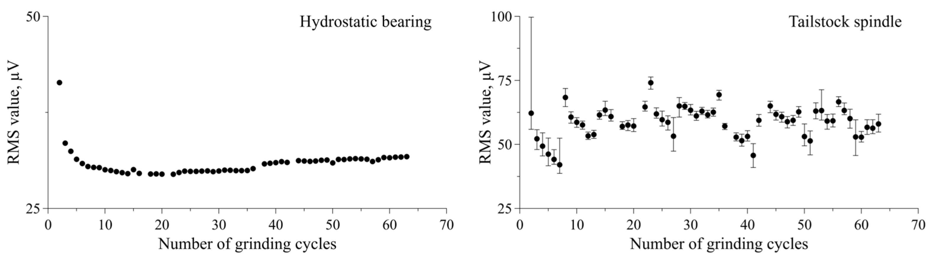
  • The RMS values derived from the AE signals acquired from the AE sensor placed on the hydrostatic bearing decreased with the increase in the number of grinding cycles. Furthermore, they exhibited a small variation for each cycle and were less affected by the grinding position than those for the AE sensor placed on the tailstock spindle.
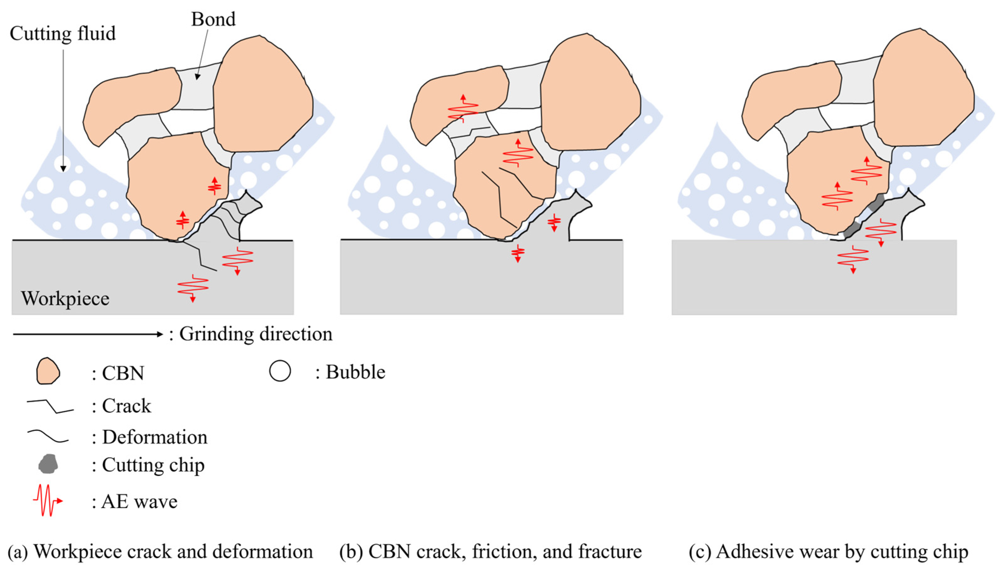
  • A comparison between the AE sensors located on the hydrostatic bearing and the tailstock spindle, respectively, facilitated by a frequency domain analysis showed differences at frequencies below 0.3 MHz and above 1 MHz. It can be concluded that the difference in frequency response below 0.3 MHz is due to the AE sensor located on the tailstock spindle detecting AE signals caused by crack propagation, breakage, and the deformation of the workpiece, whereas the AE sensor on the hydrostatic bearing detected AE signals generated by cracks, friction, and the fractures of bonds and the cBN on the grinding wheel surface.
  • To realize an effective method for monitoring grinding wheel deterioration using AE, the location of the AE sensor is an important factor. Acquiring an AE signal by positioning a sensor on the hydrostatic bearing is effective because it can extract information on grinding wheel deterioration despite the reduced signal intensity.

6. Patents

For the registration of this invention/method, Japanese unexamined patent publications No. 2022–147687, 2022–147691, and 2022–147692 are pending.

Author Contributions

Conceptualization, T.K., H.M., H.I., Y.A., A.K. and T.O.; methodology, T.K., H.M., H.I., Y.A., A.K. and T.O.; software, T.K.; validation, H.I., Y.A. and Y.W.; formal analysis, T.K.; investigation, T.K., H.I. and Y.A.; resources, A.K., T.O. and K.A.; data curation, T.K.; writing—original draft preparation, T.K. and H.M.; writing—review and editing, T.K. and H.M.; visualization, T.K. and H.M.; supervision, H.I., A.K. and T.O.; project administration, H.I. and A.K.; funding acquisition, A.K. All authors have read and agreed to the published version of the manuscript.

Funding

We carried out the content of this paper as a collaborative research project with a formal contract.

Data Availability Statement

Owing to the nature of this research, the participants of this study did not agree for their data to be shared publicly, so supporting data are not available.

Conflicts of Interest

We carried out the content of this paper as a collaborative research project with a formal contract. Authors Hideki Iwai, Yoshiaki Ando, and Yoshio Wakazono are enployees of JTEKT corporation. The remaining authors declare that the research was conducted in the absence of any commercial or financial relationships that could be construed as a potential conflict of interest.

References

  1. Yuhang, P.; Ping, Z.; Ying, Y.; Anupam, A.; Yonghao, W.; Dongming, G.; Saurav, G. New insights into the methods for predicting ground surface roughness in the age of digitalization. Precis. Eng. 2021, 67, 393–418. [Google Scholar]
  2. Supriyo, M.; Piyush, S.; Nramesh, B. A robust condition monitoring methodology for grinding wheel wear identification using Hilbert Hung transform. Precis. Eng. 2021, 70, 77–91. [Google Scholar]
  3. Changsheng, L.; Lin, S.; Shuming, Y.; Liangchi, Z.; Chuhan, W.; Zhuangde, J. Three–dimensional characterization and modeling of diamond electroplated grinding wheels. Int. J. Mech. Sci. 2018, 44, 553–563. [Google Scholar]
  4. Wojciech, K.; Dariusz, L.; Filip, S.; Anna, Z.T.; Katarzyna, T.; Grzegorz, K. Metrological basis for assessing the state of the active surface of abrasive tools based on parameters characterizing their machining potential. Measurement 2020, 165, 108068. [Google Scholar]
  5. Wojciech, K.; Krzysztof, N. Assessment of the grinding wheel active surface condition using SEM and image analysis techniques. J. Braz. Soc. Mech. Sci. Eng. 2013, 35, 207–215. [Google Scholar]
  6. Zhongde, S.; Malkin, S. Wear of Electroplated CBN Grinding Wheel. J. Manuf. Sci. Eng. 2006, 128, 110–118. [Google Scholar]
  7. Eddie, T.L.; Zhaoyan, F.; Burak, S. Real–time Grinding Wheel Condition Monitoring Using Linear Imaging Sensor. Procedia Manuf. 2020, 49, 139–143. [Google Scholar]
  8. Eddie, T.L.; Zhaoyan, F.; Burak, S. Estimation of cBN grinding wheel condition using image sensor. Procedia Manuf. 2021, 53, 286–292. [Google Scholar]
  9. Hundt, W.; Leuenberger, D.; Rehsteiner, F.; Gygax, P. An Approach to Monitoring of the Grinding Process Using Acoustic Emission (AE) Technique. CIRP Ann. 1994, 43, 295–298. [Google Scholar] [CrossRef]
  10. Hassui, A.; Diniz, A.E.; Oliveira, J.F.G.; Felipe, J.; Gomes, J.J.F. Experimental evaluation on grinding wheel wear through vibration and acoustic emission. Wear 1998, 217, 7–14. [Google Scholar] [CrossRef]
  11. Liao, T.W.; Ting, C.F.; Qu, J.; Blau, P.J. A wavelet–based methodology for grinding wheel condition monitoring. Int. J. Mach. Tools Manuf. 2007, 47, 580–592. [Google Scholar] [CrossRef]
  12. Liao, T.W. Feature extraction and selection from acoustic emission signals with an application in grinding wheel condition monitoring. Eng. Appl. Artif. Intell. 2010, 23, 74–84. [Google Scholar] [CrossRef]
  13. Yang, Z.; Yu, Z. Grinding wheel wear monitoring based on wavelet analysis and support vector machine. Int. J. Adv. Manuf. Technol. 2012, 62, 107–121. [Google Scholar] [CrossRef]
  14. Arun, A.; Rameshkumar, K.; Unnikrishnan, D.; Sumesh, A. Tool Condition Monitoring of Cylindrical Grinding Process Using Acoustic Emission Sensor. Mater. Today Proc. 2018, 5, 11888–11899. [Google Scholar] [CrossRef]
  15. Krishnan, P.S.; Rameshkumar, K. Grinding wheel condition prediction with discrete hidden Markov model using acoustic emission signature. Mater. Today Proc. 2021, 46, 9168–9175. [Google Scholar] [CrossRef]
  16. Shen, C.H. Acoustic emission based grinding wheel wear monitoring: Signal processing and feature extraction. Appl. Acoust. 2022, 196, 108863. [Google Scholar] [CrossRef]
  17. Webster, J.; Marinescu, I.; Bennett, R. Acoustic Emission for Process Control and Monitoring of Surface Integrity during Grinding. CIRP Ann. 1994, 43, 229–304. [Google Scholar] [CrossRef]
  18. Mokbel, A.A.; Maksoud, T.M.A. Monitoring of the condition of diamond grinding wheels using acoustic emission technique. J. Mater. Process. Technol. 2000, 101, 292–297. [Google Scholar] [CrossRef]
  19. Lee, D.E.; Hwang, I.; Valente, C.M.O.; Oliveira, J.F.G.; Dornfeld, D.A. Precision manufacturing process monitoring with acoustic emission. Int. J. Mach. Tools Manuf. 2006, 46, 176–188. [Google Scholar] [CrossRef]
  20. Hase, A.; Sato, Y.; Shinohara, K.; Arai, K. Identification of the Wear Process of a Silver–Plating Layer by Dual Acoustic Emission Sensing. Coatings 2021, 11, 737. [Google Scholar] [CrossRef]
  21. Wang, Z.; Wang, H.; Li, X.; Jianhua, Y.; Xu, R. Surface Integrity of Powder Metal lurgy Superalloy FGH96 Affected by Grinding with Electroplated CBN Wheel. Procedia CIRP 2020, 87, 204–209. [Google Scholar]
  22. Zhenzhen, G.; Huan, Q.; Yi, Z.; Liwu, S.; Hao, N.L.; Wenfeng, D. On the tribology and grinding performance of graphene–modified porous composite–bonded CBN wheel. Ceram. Int. 2021, 47, 3259–3266. [Google Scholar]
  23. Michal, K.; Fredy, K.; Konrad, W. Comparison of lubrication conditions for grinding of mild steel with electroplated cBN wheel. CIRP J. Manuf. Sci. Technol. 2017, 18, 53–59. [Google Scholar]
  24. Adriano, B.; Walter, L.W. Dynamic in–process characterization method based on acoustic emission for topographic assessment of conventional grinding wheels. Wear 2018, 406–407, 218–229. [Google Scholar]
  25. Imai, K.; Hase, A. Identification of Tribological Phenomena in Glass Grinding by Acoustic Emission Sensing. Tribol. Online 2022, 17, 86–96. [Google Scholar] [CrossRef]
  26. Racindra, H.V.; Srinivasa, Y.G.; Krishnamurthy, R. Acoustic emission for tool condition monitoring in metal cutting. Wear 1997, 212, 78–84. [Google Scholar] [CrossRef]
  27. Hase, A.; Wada, M.; Mishima, H. Scanning electron microscope observation study for identification of wear mechanism using acoustic emission technique. Tribol. Int. 2014, 72, 51–57. [Google Scholar] [CrossRef]
  28. Hase, A.; Wasa, M.; Koga, T.; Mishima, H. The relationship between acoustic emission signals and cutting phenomena in turning process. Int. J. Adv. Manuf. Technol. 2014, 70, 947–955. [Google Scholar] [CrossRef]
  29. Ramadan, S.; Gaillet, L.; Tessier, C.; Idrissi, H. Detection of stress corrosion cracking of high–strength steel used in prestressed concrete structures by acoustic emission technique. Appl. Surf. Sci. 2008, 254, 2255–2261. [Google Scholar] [CrossRef]
  30. Hase, A.; Mishina, H.; Wada, M. Correlation between features of acoustic emission signals and mechanical wear mechanisms. Wear 2012, 292–293, 144–150. [Google Scholar] [CrossRef]
  31. Kon, T.; Mano, H.; Iwai, H.; Korenaga, A.; Ohana, T.; Ashida, K.; Sato, H.; Wakazono, Y. Propagation characteristics of acoustic emission waves in liquid media in near–field. Precis. Eng. 2022, 77, 220–226. [Google Scholar] [CrossRef]
Figure 1. Experimental setup.
Lubricants 12 00100 g001
Figure 2. Schematic of workpiece.
Lubricants 12 00100 g002
Figure 3. Typical raw AE signal during grinding.
Lubricants 12 00100 g003
Figure 4. Schematic of the experimental procedure.
Lubricants 12 00100 g004
Figure 5. Surface roughness of the workpiece plotted against the number of grinding cycles.
Lubricants 12 00100 g005
Figure 6. Raw AE signals acquired from AE sensors located at different positions during grinding tests (upper: hydrostatic bearing; lower: tailstock spindle).
Lubricants 12 00100 g006
Figure 7. RMS values calculated from roughing AE signals (left: hydrostatic bearing; right: tailstock spindle).
Lubricants 12 00100 g007
Figure 8. FFT spectra between 0.1 and 0.5 MHz for roughing AE signals plotted against the number of grinding cycles (left: hydrostatic bearing; right: tailstock spindle).
Lubricants 12 00100 g008
Figure 9. FFT spectra between 1.0 and 2.0 MHz for roughing AE signals plotted against the number of grinding cycles (left: hydrostatic bearing; right: tailstock spindle).
Lubricants 12 00100 g009
Figure 10. RMS values calculated from AE signals filtered with a 1 MHz HPF plotted against the number of grinding cycles (left: hydrostatic bearing; right: tailstock spindle).
Lubricants 12 00100 g010
Figure 11. Schematic of the different AE sources of AE waves detected by both sensors.
Lubricants 12 00100 g011
Table 1. Specifications of the cBN wheel.
Diameter of grinding wheel, mm350
Width of grinding wheel, mm20
Abrasive graincBN
Bond materialVitrified
Grain size#120
Concentration150
Table 2. Experimental conditions of the grinding tests.
Wheel peripheral speed, m/s45
Work rotational speed, min−1100
Grinding stock removal rate Z’, mm3/(mm·s)10
Stock removal in one plunge grinding, mm3722.4
Roughing feed, mm/min3.23
Semi–finishing feed, mm/min0.170
Finishing feed, mm/min0.0213
Table 3. Number of interfaces in existence before the AE waves reached each AE sensor.
AE Sensor Location
Tailstock SpindleHydrostatic Bearing
Number of interfaces67
Details of interfaceWorkpiece

Lubricating grease

Tailstock spindle

Vacuum grease

Separate shaft holder

Thermoplastic adhesive

AE sensor
cBN

Vitrified

Base metal

Grinding wheel shaft

Lubricating oil
(Mobil Velocite 3)

Hydrostatic bearing

Instant adhesive

AE sensor
Table 4. Effects of AE sensor location on AE signal characteristics.
AE Signal CharacteristicAE Sensor Location
Tailstock SpindleHydrostatic Bearing Supporting Grinding Wheel Spindle
IntensityLargeMedium
Variation in amplitude at same grinding positionLargeVery small
Effect of grinding position on skewer-like workpieceLargeVery small
Disclaimer/Publisher’s Note: The statements, opinions and data contained in all publications are solely those of the individual author(s) and contributor(s) and not of MDPI and/or the editor(s). MDPI and/or the editor(s) disclaim responsibility for any injury to people or property resulting from any ideas, methods, instructions or products referred to in the content.

