Abstract
Part of the gas phase within the bearing emanates from the gaseous lubricating medium generated by the phase transition of the liquid lubricant under low pressure, while the remaining portion originates from the expansion of gases, such as air, present in the lubricant. This study delves into the impact of vapor and gas cavitation on the stability of the rotor-journal bearing system. Utilizing computational fluid dynamics (CFD), a 3D transient lubrication model is developed for the rotor-journal bearing system. This model integrates a combined cavitation approach, encompassing both vaporous and gaseous cavitation phenomena. Based on a new structured dynamic mesh method, the journal orbits are obtained when the journal moves in the rotor-journal bearing system. In vaporous and gaseous cavitation, shear stress and non-condensable gases (NCG) are incorporated successively. Compared with the combined cavitation model, the basic cavitation model journal orbit amplitude is significantly larger than the combined cavitation model. The carrying capacity of journal bearings under the basic cavitation model is overestimated, leading to a more conservative prediction for system stability.
1. Introduction
During the operation of the journal bearing, the liquid lubricating medium vaporizes under the action of low pressure, resulting in a cavitation effect. This phenomenon significantly influences the rotor’s stability. Cavitation within the oil film disrupts its continuity, creating unstable lubrication conditions, particularly when operating under high-speed and high-load conditions. Such instability can lead to a decline in bearing performance and, in severe cases, result in damage or failure. The stability of the rotor-journal bearing system holds pivotal significance in large rotating machines such as compressor turbines and machine tools [1]. Scholars have conducted extensive analytical studies on the dynamic characteristics of bearings based on the solution to the Reynolds equation [2,3,4]. Numerically, the stability of the rotor-journal bearing system was initially studied by solving dynamic characteristic coefficients during the early stages of bearing dynamic characteristic research. Xiong et al. [5] investigated the influence of the amplitude of perturbation on the stiffness and damping coefficients. Taking the deformation of the bearing bush into account, Liang et al. [6] studied the influence of disturbance amplitude on the stiffness coefficients of water-lubricated cylindrical bearings. Ren and Feng [7] calculated the instability speed of journal bearings used for air compressors in differently structured fuel cell vehicles. Wang et al. [8] investigated the effect of different structural parameters on the instability speed of rolling mill journal bearings. Xu et al. [9] established a water-lubricated fluid lubrication model considering turbulence, inertia, and misalignment effects and studied the dynamic characteristics of bearings under different operating conditions based on the four-degree-of-freedom equations. Liu et al. [10] proposed a calculation method of 16 dynamic coefficients considering the deformation of the lining and analyzed the influence of structural parameters such as eccentricity on the dynamic characteristics of bearings. However, the linear oil film force is only valid under the condition of small oil film whirling motion and is unacceptable for the prediction of large unbalanced responses or oil film whirling motion [11,12,13]. By iteratively solving the fluid dynamic pressure lubrication equation and the rotor dynamics equation, nonlinear transient analysis methods offer a more comprehensive approach to analyzing rotor stability and predicting central trajectories. Therefore, a nonlinear oil film force model is developed by directly integrating the oil film pressure acting on the journal surface, enabling direct calculation of journal orbits. By solving the Reynolds equation, Lin et al. [14] studied the influence of non-Newtonian characteristics of the lubricating medium on the unstable speed of the rotor and found that the non-Newtonian lubricating medium has a wider instability boundary than the Newtonian medium. Wang and Khonsari [15] investigated the effect of inlet position and pressure on the critical instability speed in bearings. Castro et al. [16] analyzed the effects of bearing clearance, length-to-diameter ratio, and oil viscosity on oil film whirling motion and oscillation in a single-disk flexible rotor-journal bearing system. Chasalevris et al. [17,18] analyzed the exact and approximate solutions of Reynolds equations for journal bearings and obtained the important design parameters and lubrication characteristics of finite journal bearings. Additionally, Xie et al. [19] resolved a coupled model involving water film pressure-rotor dynamics equations, conducting comprehensive rotor dynamics analyses encompassing vibration, start-stop, and impact analyses.
Although Dousti et al. [20] developed the extended Reynolds equation incorporating inertia effects, computational fluid dynamics (CFD) methods demonstrate greater efficacy in handling intricate flow physics, including inertia effects, 3D complexities, and multiphase flows. CFD methods exhibit reduced reliance on empiricism and model tuning compared to the extended Reynolds equation [21,22]. Nassab and Moayer [23] established a CFD-THD (thermohydrodynamic) lubrication model for journal bearings and found that the inertia effect would have a significant influence on the dynamic pressure lubrication of journal bearings under light loads, high speeds, and large clearances [24]. Papadopoulos et al. [25] established the CFD-THD lubrication model of textured pan-shaped pad thrust bearings and studied the influence of operating parameters and texture parameters on lubrication performance. Tauviqirrahman et al. [26] solved the lubrication characteristics of bearings of different materials using a coupled CFD-FSI (Fluid–Structure Interaction) method and investigated the relationship between bearing materials and bearing friction noise. In order to obtain the nonlinear oil film force model of journal bearings based on CFD, it is necessary to extend the CFD lubrication analysis model of journal bearings to the transient flow field by using the dynamic mesh method. But the negative mesh volume of the CFD model is more easily generated because of the small clearance flow field of the oil film in the journal bearing. Li et al. [27] established a transient three-dimensional lubrication model of journal bearings based on a new structured dynamic mesh method and carried out the lubrication and stability analysis of journal bearings.
The gases produced within the bearing due to cavitation are not only the result of the phase transition from liquid to gas as the pressure drops in the cavitated region but also include gases that are sparingly or immiscible in the lubricating medium, referred to as non-condensable gases [28]. Therefore, within the flow field of journal bearings, there are two forms of cavitation: vaporous and gaseous cavitation. For the vaporous cavitation, Singhal et al. [29] proposed the full cavitation model by considering the influence of bubble formation and transport, pressure and velocity fluctuation, as well as the non-condensable gas. Based on the full cavitation model, Li et al. [30] put forward the transient calculation method to analyze the transient flow field of a journal bearing in a rotor-bearing system. Furthermore, Li et al. [31] made a detailed derivation of shear stress cavitation and found that the magnitude of the loading capacity of shear stress cavitation is smaller than the loading capacity without shear stress cavitation due to the decreased ultimate pressure. For gaseous cavitation, Lin et al. [32] described the relationship between gas phase volume and pressure through linear functions and established a thermoelastic fluid dynamic pressure lubrication model for journal bearings. Song et al. [33] took the gas phase volume as a function of the intrinsic solubility of lubricating oil and proposed a dissolution cavitation model of journal bearings. Zhang et al. [34] investigated the relationship between the non-condensable gas content and the rotor static equilibrium positions in journal bearings. So far, the influence of the combined effect of gaseous cavitation and vaporous cavitation on bearing stability has not been fully covered.
The above literature mostly uses shear cavitation or non-condensable gas cavitation alone, and the calculation results are quite different from the actual situation. In this paper, gaseous cavitation considering the content of non-condensable gases and vaporous cavitation considering shear stress are combined to modify the basic oil film cavitation model. Based on the combined cavitation model and the structured dynamic mesh method developed by our research group, a three-dimensional transient flow field model is established to obtain the journal orbits and frequency under two cavitation models (the basic cavitation model and the combined cavitation model). The influence of shear cavitation and gaseous cavitation on the stability of journal bearings is investigated.
2. Theory of the Model
2.1. Governing Equations of Flow Field
During the operation of journal bearings, the bearing gap flow field can be regarded as a convergence–divergence type of small gap flow. The decrease in liquid film pressure inside the divergent wedge will lead to cavitation of liquid film, and the resulting bubble will collapse due to the increase in pressure in the convergent wedge. Considering cavitation, there are gas and liquid phases in the flow field of the journal bearing. The “Mixture” model is adopted to describe a two-phase flow. The mixture continuity equation of the flow field in journal bearing [35] is
where is mass-averaged velocity, is the mixture density.
The mixture momentum equation [35] is
where n and k are the number of phases, is body force and μm is viscosity of mixture [35],
is the drift velocity of secondary phase k,
2.2. Governing Equation of Cavitation Model
The working fluid is assumed to be a mixture of liquid, vapor, and non-condensable gases. The volume of non-condensable gases changes with film pressure during gaseous cavitation, and a separate vapor mass fraction transport equation with a source term is solved to model cavitation:
where is the vapor mass fraction, γ is the effective exchange coefficient, Re and Rc are vapor generation and condensation rates, respectively, which are expressed in the full cavitation model as follows [29]:
where k is the local turbulent kinetic energy, σ is the coefficient of surface tension of liquid, Ce and Cc are empirical constants and Ce = 0.02, Cc = 0.01, is the mass fraction of vapor, is the mass fraction of non-condensable gas (NCG), and pv is the liquid saturation vapor pressure. The suffixes l and v denote the liquid and vapor phases.
However, shear stress and NCG based on air solubility are not considered in the basic cavitation model. The principal normal stress cavitation criterion and theory of air intrinsic solubility are applied to the vaporous cavitation and gaseous cavitation, respectively, in the combined cavitation model. In vaporous cavitation, the shear stress affects the amplitude of the incipient cavitation pressure in the oil film. A stress cavitation criterion is proposed and verified [31], and the ultimate principal stress cavitation criterion equations are as follows:
2.3. NCG Based on Air Intrinsic Solubility
When the air in the lubricating flow field expands at low pressure, gaseous cavitation happens. It is assumed that the density of air ρg follows the ideal gas state equation:
where p and T are the pressure and temperature of the lubricating flow field, respectively, M is the molar mass of air, 28.97 × 10⁻³ kg/mol, and R is the ideal gas constant, 8.314 J/(mol∙K). The volume fraction of air gv can be calculated by:
where g,inm is the mass fraction of air contained in the lubricant when entering the journal bearing. Guo et al. [36] measured the gas content of the lubricating oil under different conditions, and the equation of the air intrinsic solubility δ in the lubricating oil is as follows:
where p0 is the standard pressure.
Therefore, the volume fraction g,inv of air contained in the lubricant when entering the journal bearing can be calculated by
where T0 is the temperature at standard state, Vg and Voil are the volumes of air and liquid lubricating oil, respectively.
The volume fraction is converted to the mass fraction by the following equation:
where ρg and ρoil are the densities of air and liquid lubricating oil, respectively.
3. Model and Solution Method
3.1. Physical and Computational Models
This paper takes journal bearings as the research object, and the bearing assembly diagram is shown in Figure 1a. The oil inlet is set on the inner side of the bearing, and the oil groove is set on the outer side to ensure that the lubricating oil flows smoothly into the clearance between the rotor and journal bearing. The lubricating medium enters from the center of the bearing and flows out to both sides, forming a hydrodynamic oil film under the action of the high-speed rotation of the rotor shaft to realize the support of the rotor, as shown in Figure 1b. The rotor gradually produces eccentricity in the process of rotation. The Jeffcott rotor-journal bearing system is applied to study oil film whirling motion, as illustrated in Figure 2. The journal is subject to rotor gravity and oil film force in the x and y directions. The structure and operating parameters of the bearing model are listed in Table 1. As the fluid domain in the simulation calculation process, the lubricating oil film is meshed, as shown in Figure 1d.
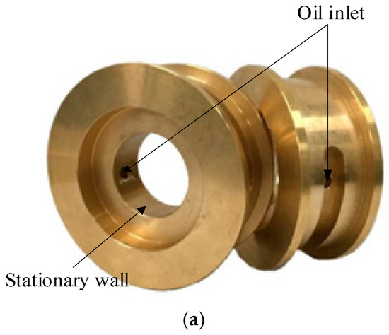
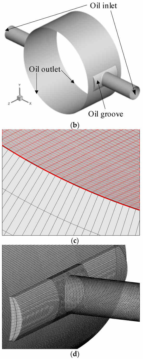
Figure 1.
Schematic of the journal bearing. (a) Practical model. (b) CFD model. (c) Solid domain and fluid domain grid at the oil film. (d) Oil groove mesh.
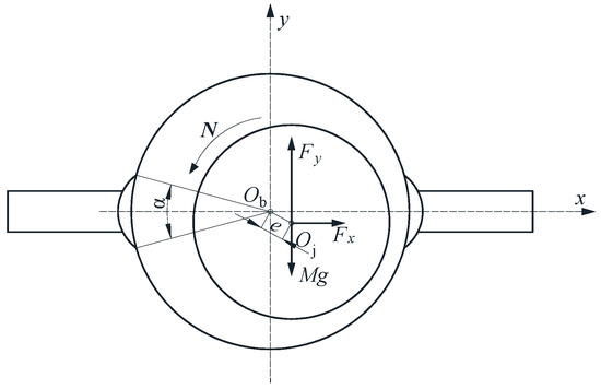
Figure 2.
Rotor-journal bearing system.

Table 1.
Parameters of journal bearing model.
The structured mesh is utilized for the oil film. The maximum pressures, x-directional oil film forces, and y-directional oil film forces calculated by the transient calculated model with different numbers of meshes are shown in Table 2. To balance the calculation accuracy and the requirements for proper use of the machine’s memory and simulation time, the Mesh 3 density (mesh aspect ratio of 87) is employed for the simulated calculation of this study. The Mesh 3 density is 6, 40, and 200 divisions in the radial, axial, and circumferential directions, respectively. The cylindrical oil inlet intersects with the curved oil groove, resulting in a complex structure, so the unstructured grid is used in the oil groove. The number of layers of radial mesh in bearing pad rs is 16. The parameters used in the numerical analysis are listed in Table 1. The flow field is selected as laminar flow. The tilting of the journal and the deformation of the bearing are ignored in the calculation process.
Table 2.
Mesh independence analysis.
The motion equations of the journal are described as follows:
Since pressure has a major role in the oil film bearing capacity, the effect of viscous forces is neglected in order to simplify the calculation and analysis process. So Fx and Fy are obtained by integrating the journal surface force as follows:
3.2. Calculation Procedure
The coupling calculation of bearing transient flow field parameters and rotor motion parameters is realized based on a structured dynamic mesh [37]. The algorithm guarantees the mesh quality of the oil film clearance when the journal suffers a large disturbance. It is loaded into Fluent in the form of the user-defined function (UDF) for the mesh movement calculation. The flow chart of the calculation procedure for this model is displayed in Figure 3. Firstly, the steady-state calculation of the model is conducted. Secondly, the total calculation time T and time step are set to perform transient computation and to obtain the non-linear oil film forces Fx and Fy by integration. Thirdly, in every time step, substitute the oil film forces into the rotor dynamics equations to calculate the x and y direction accelerations, velocities, and displacements of the rotor motion. The axis and grid node coordinates are computed, and the flow field grid is updated by means of a dynamic grid algorithm. Finally, if the next time step is greater than the total time step, the calculation ends. Otherwise, iterate through the preceding steps.
Figure 3.
Flow chart of calculation procedure.
The governing equations of flow fields are solved using the finite volume method. And the SIMPLEC and PISO schemes are adopted in steady-state and transient computation, respectively. The double precision solver is adopted for the calculation. The PRESTO! scheme is applied for pressure interpolation because of the high-speed rotating flow in the journal bearings.
4. Experimental Setup
A full-scale test rig, aligned with the simulation’s scale, has been constructed. The schematic diagram of the test rig is shown in Figure 4, and the main parameters are shown in Table 3. The shaft is supported by two journal bearings, and lubricating oil is available to lubricate the clearance of the shaft and journal bearings. The configuration is equipped with three counterweight disks that realize the setting of different imbalances. The sensor system mainly consists of a photoelectric sensor and six identical eddy current displacement sensors. The photoelectric sensor is responsible for measuring the phase, which can be used for determining dynamic balancing and rotational speed. The eddy current displacement sensors are arranged at the counterweight plate, left and right journal bearings, respectively, which are responsible for measuring the journal orbits.
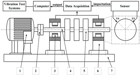
Figure 4.
Schematic diagram of the single-disk journal bearings test rig. (1. Variable frequency Ac motor 2. Coupling 3. Journal bearings 4. Rotor 5. Weight plate 6. Bearing housing 7. Base plate).
Table 3.
Main Parameters.
The inside of the bearing seat is designed with tooling to test the journal bearing with the maximum diameter of 250 mm, as demonstrated in Figure 5a. The upper bearing cover combines with the bearing seat by bolts, which realizing the fixing of bearing, as displayed in Figure 5b. The lubrication system consists of an oil supply station, an oil return station, a ball valve, and a pressure gauge. The views of the oil channel in the bearing seat are displayed in Figure 6. The lubricating oil supplied by the oil supply station flows into the oil inlet on the right side of the bearing, as shown in Figure 6a. After flowing through the tooling, lubricating oil enters the internal clearance of the bearing radially, and then lubricating oil flows out from both sides of the bearing, as shown in Figure 6b. Further, it escapes from the left exit of the journal bearing to the oil returning station, as shown in Figure 6a at the end. Finally, the oil returning station pumped the lubricating oil back into the oil supplying station, which increased the circulation of the lubricating oil.
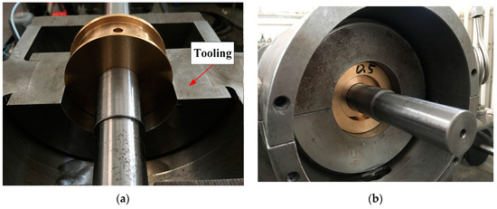
Figure 5.
Local schematic diagram of the rotor-journal bearing test rig. (a) The installation place of journal bearing. (b) Fit between bearing cap and seat.
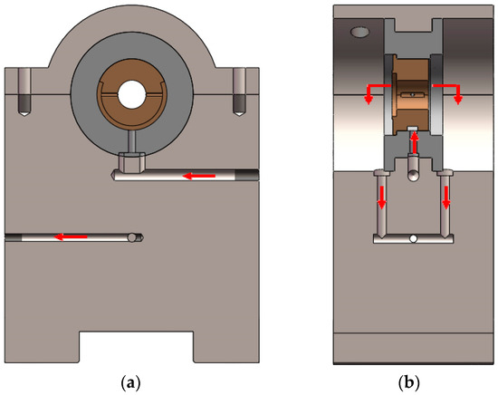
Figure 6.
Lubrication channel inside the bearing seat. (a) Main cross-section view. (b) Lateral cross-section view.
5. Result and Discussion
5.1. Comparison Study When L/D = 0.5
As demonstrated in Figure 7 and Figure 8, a comparison of the journal orbits and frequency spectrum calculated with the basic and combined cavitation model when N = 2000 r/min (f = 33.3 Hz) is carried out. The journal orbits with the combined cavitation model are in the fourth quadrant, and only the rotational speed frequency vibration appears in the frequency spectrum. While the center of the journal orbits with the basic cavitation model, it is near the journal bearing center. And the half-speed frequency component is much larger than the rotational speed frequency component, which means that the system turns into an unstable state. Therefore, the journal orbit with the basic cavitation model is much larger than that with the combined cavitation model. This is because shear stress and gas cavitation are ignored in the basic cavitation model. And the bearing capacity is overvalued, causing a conservative forecast for the stability of the rotor system.
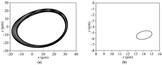
Figure 7.
Comparison of whirling orbits with different cavitation models (L/D = 0.5, N = 2000 r/min). (a) Basic cavitation model. (b) Combined cavitation model.
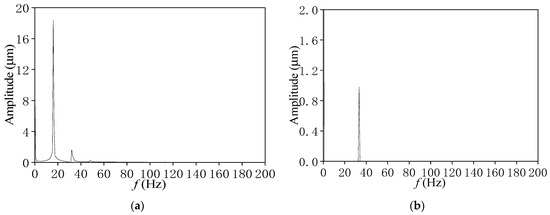
Figure 8.
Comparison of frequency spectra with different cavitation models (L/D = 0.5, N = 2000 r/min). (a) Basic cavitation model. (b) Combined cavitation model.
In the process of increasing speed to 3000 r/min and 4000 r/min, the whirling orbits are displayed in Figure 9 and Figure 10. With different cavitation models, significant differences occur in the change of bearing trajectories and the stability of the rotor system as the rotational speed increases. For the combined cavitation model, the orbit center approaches the journal bearing center, and the journal orbits become larger gradually but keep their regularly elliptical shape. With the basic cavitation model, the journal orbits expand continually with the increase in rotational speed, but there is no phenomenon of rub impact between bearing bush and rotor. This is because the rapid increase in oil film force forms the journal’s limit circle motion due to the hydrodynamic force’s nonlinear effect, which is called the “limit cycle” phenomenon [38]. Combining with Figure 11, it can be seen that the journal orbits still have only the 65 Hz component when N = 4000 r/min (f = 66.7 Hz), the rotor keeps stabilized the rotational speed frequency whirling motion in the combined cavitation model. However, for the basic cavitation, the half-speed frequency component (35 Hz) is further increased, and the rotational speed frequency is basically completely submerged, indicating that the rotor system is completely unstable at this speed. The vibration frequency in the rotor movement is mainly concentrated in the half-speed frequency rather than the rotational speed frequency, which will lead to excessive vibration of the whole rotor system and may have an effect on the operational stability of the rotor. Excessive vibration will even further accelerate the wear of the bearing and reduce its service life.
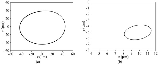
Figure 9.
Comparison of whirling orbits with different cavitation models (L/D = 0.5, N = 3000 r/min). (a) Basic cavitation model. (b) Combined cavitation model.
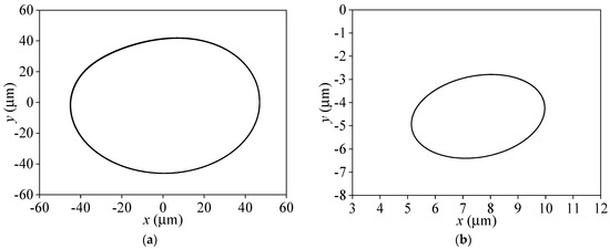
Figure 10.
Comparison of whirling orbits with different cavitation models (L/D = 0.5, N = 4000 r/min). (a) Basic cavitation model. (b) Combined cavitation model.
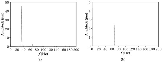
Figure 11.
Comparison of frequency spectra with different cavitation models (L/D = 0.5, N = 4000 r/min). (a) Basic cavitation model. (b) Combined cavitation model.
As shown in Figure 12 and Figure 13, when the rotational speed further improves to 5000 r/min (f = 83.3 Hz), the journal orbits calculated by the basic cavitation model maintain the limit circle motion with the half-speed frequency component, and the half-speed frequency component increases continually, showing that the system is in a state of complete instability. In contrast, the shape of the journal orbits based on the combined cavitation model changes from the elliptical to the “inner figure eight” shape. The journal orbits are further enlarged, and the orbit center is closer to the bearing center. When N = 5000 r/min, a vibration at about half-speed frequency (42 Hz), indicating that oil film whirling motion appears.
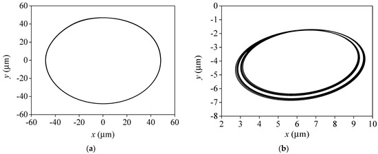
Figure 12.
Comparison of whirling orbits at different cavitation models (L/D = 0.5, N = 5000 r/min). (a) Basic cavitation model. (b) Combined cavitation model.
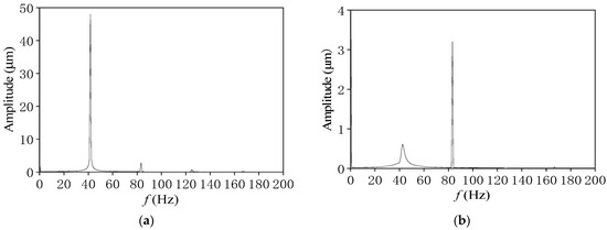
Figure 13.
Comparison of frequency spectra at different cavitation models (L/D = 0.5, N = 5000 r/min). (a) Basic cavitation model. (b) Combined cavitation model.
In the summary analysis it was found that the journal orbit amplitude of the combined cavitation model is obviously smaller than that of the basic cavitation model. With the increase in rotational speed, the journal orbit center of the combined cavitation model is gradually closer to the bearing center, and its journal orbit is also gradually enlarged. When the rotational speed is increased to 5000 r/min, the half-speed frequency component appears in the combined cavitation model, and its journal orbit also changes. The half-speed frequency component of the base cavitation model continues to increase with the increase in rotational speed and almost completely submerges the rotational speed frequency. Therefore, compared with the combined cavitation model, the base cavitation model is relatively conservative in predicting the journal trajectory.
The whirling orbits and frequency spectra of the rotor at different rotational speeds with this journal-bearing support are given in Figure 14. When the rotational speed is 4900 r/min, the rotor is a stable power-frequency vortex. When the rotational speed increases to 5100 r/min, the half-frequency begins to appear on the frequency domain graph, but the trajectory has not yet appeared in the obvious “inner figure eight” shape. When the rotational speed reaches 5300 r/min, the oil film vortex begins to appear, and the time domain graph shows a more obvious “inner figure eight” shape, and the frequency domain graph shows obvious half-frequency components. In the comparative simulation, using the modified cavitation model, the bearing appeared as a half-frequency vortex near 5000 r/min, and the trajectory showed the shape of “inner figure eight”, so the test results achieved good consistency with the numerical simulation results.
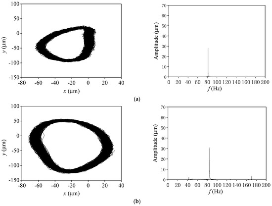
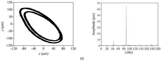
Figure 14.
Whirling orbits and frequency spectrum (L/D = 0.5). (a) N = 4900 r/min. (b) N = 5100 r/min. (c) N = 5300 r/min.
5.2. Comparison Study When L/D = 1.0
For the journal bearings with L/D = 1.0, as displayed in Figure 15 and Figure 16, when N = 2000 r/min (f = 33.3 Hz), the whirling motion orbits for the basic cavitation model present a “limit cycle” shape dominated by half-speed frequency, indicating that the rotor-journal bearing system has lost stability. Although a faint half-frequency component appears in the frequency spectrum with the combined cavitation model, the journal orbit calculated by the combined cavitation still exhibits a regular elliptical shape and a small journal orbit amplitude.
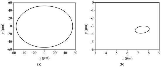
Figure 15.
Comparison of whirling orbits at different cavitation models (L/D = 1, N = 2000 r/min). (a) Basic cavitation model. (b) Combined cavitation model.
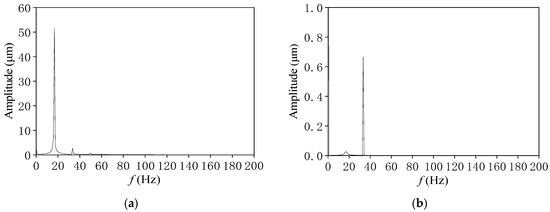
Figure 16.
Comparison of frequency spectra at different cavitation models (L/D = 1, N = 2000 r/min). (a) Basic cavitation model. (b) Combined cavitation model.
In Figure 17 and Figure 18, when the rotational speed rises to 3000 r/min, the amplitude of journal orbits based on the combined cavitation model gradually increases, and the half-speed frequency component is enhanced with an “inner figure eight” shape track, indicating the appearance of the oil film whirling motion. In Figure 19 and Figure 20, with the combined cavitation model, the half-speed frequency component is more obvious, and the shape of journal orbits presents a more obvious “internal figure eight” in the process from 3000 r/min increasing to 5000 r/min. At corresponding speeds, the journal orbits for the basic cavitation model still keep the “limit cycle motion”, showing the rotor is always in an unstable state in the basic cavitation model. The numerical results further indicate that the prediction of system stability by the basic cavitation model is more conservative than that by the combined cavitation model.
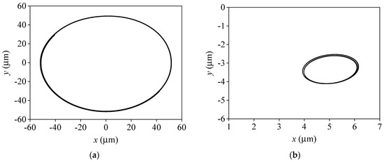
Figure 17.
Comparison of whirling orbits at different cavitation models (L/D = 1, N = 3000 r/min). (a) Basic cavitation model. (b) Combined cavitation model.
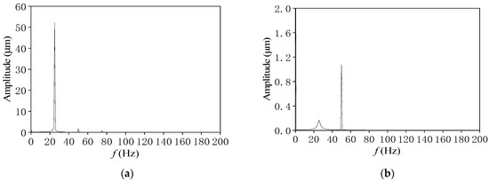
Figure 18.
Comparison of frequency spectra at different cavitation models (L/D = 1, N = 3000 r/min). (a) Basic cavitation model. (b) Combined cavitation model.
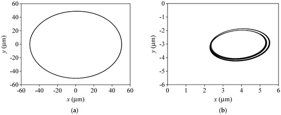
Figure 19.
Comparison of whirling orbits at different cavitation models (L/D = 1, N = 4000 r/min). (a) Basic cavitation model. (b) Combined cavitation model.
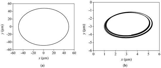
Figure 20.
Comparison of whirling orbits at different cavitation models (L/D = 1, N = 5000 r/min). (a) Basic cavitation model. (b) Combined cavitation model.
In summary, it can be seen that when L/D = 0.5 in the combined cavitation model, the rotor at 5000 r/min results in the journal orbits appearing as an “inner figure eight” shape, while when L/D = 1, the rotor at lower speed conditions (3000 r/min) results in the journal orbits appearing as an “inner figure eight” shape. The results show that as the bearing aspect ratio increases, the stability of the rotor further decreases, which is consistent with the rule found by Castro et al. [16] through bifurcation analysis.
The test results of the rotor supported by this bearing with an aspect ratio (L/D) of 1.0 are given in Figure 21. At low rotational speeds, the whirling orbits are approximately elliptical and maintain a steady power-frequency vibration. After crossing the first-order critical speed (the critical speed of the system was tested to be 2700 r/min~2900 r/min), when the speed was increased to 3500 r/min, a half-frequency appeared in the frequency spectrum, and the whirling orbits began to show the shape of the “inner figure eight”, which indicated that oil film whirling motion begins to occur in the rotor at this rotational speed. With the further increase in rotational speed, gradually away from the critical speed, the rotor vibration gradually decreased, but the half-frequency component was gradually rising. Compared with the numerical simulation results, using the combined cavitation model, half-frequency vortexing occurs at 3000 r/min, and the trajectory shows the shape of “inner figure eight”, so the test results and the numerical simulation results are in good agreement.
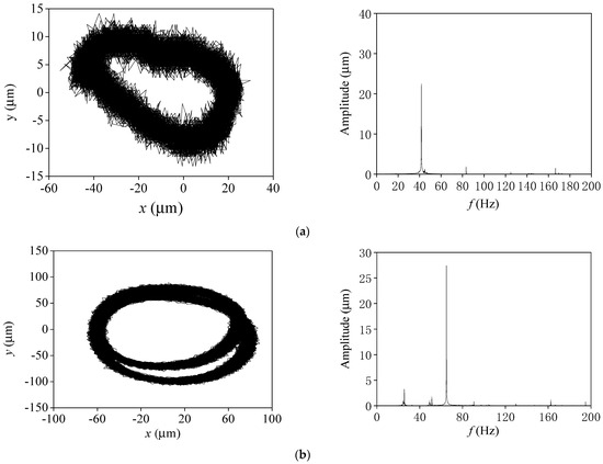
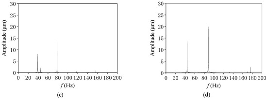
Figure 21.
Whirling orbits and frequency spectra (L/D = 1). (a) N = 2500 r/min. (b) N = 3500 r/min. (c) N = 4700 r/min. (d) N = 5300 r/min.
6. Conclusions
In this paper, based on the combined cavitation model and considering shear stress and non-condensable gas (NCG) in the lubricating flow field of journal bearings, the transient lubrication model is established. The whirling orbits and frequencies are obtained with the basic and combined cavitation models. The stability of the rotor system supported by journal bearings with different L/D is analyzed. The following conclusions can be drawn:
- (1)
- With different cavitation models, significant differences occur in the change of bearing trajectories and the stability of the rotor system as the rotational speed increases. Based on the combined cavitation model, the journal whirling orbits present a regular elliptical shape at low speed. With the increase in rotational speed, the whirling orbits change into an “inner figure eight” shape. With the basic cavitation model, the journal orbits expand continually with the increase in rotational speed and finally form the limit circle motion of the journal, but there is no phenomenon of rub impact between bearing bush and rotor. The increase in rotational speed causes a gradual rise in the half-speed frequency component, leading to a gradual destabilization of the rotor system.
- (2)
- When L/D = 0.5 in the combined cavitation model, the rotor at 5000 r/min results in the journal orbits appearing in an “inner figure eight” shape, while when L/D = 1, the rotor at lower speed conditions (3000 r/min) results in the journal orbits appearing an “inner figure eight” shape. The results show that as the bearing aspect ratio increases, the stability of the rotor further decreases. The test results for both bearings achieved good agreement with the numerical simulation results using the modified cavitation model.
- (3)
- Compared with the basic cavitation model, the combined cavitation model journal orbit amplitude is significantly smaller than the basic cavitation model. Under the basic cavitation model, the load carrying capacity of journal bearings is overestimated due to the neglect of shear stresses and gas cavitation (NCG), leading to an overly conservative prediction of system stability.
Author Contributions
Conceptualization, L.S. and J.S.; Methodology, T.J. and Q.X.; Software, L.S. and Q.X.; Validation, T.J. and Z.L. (Zhen Li); Writing—original draft, J.S. and W.X.; Writing—review and editing, Z.L. (Zhaozeng Liu) and W.X. All authors have read and agreed to the published version of the manuscript.
Funding
This research was funded by the National Natural Science Foundation of China, grant number 52176050, and the General Program of Natural Science Foundation of Shandong Province, grant number ZR2020ME174. The APC was funded by China University of Petroleum.
Data Availability Statement
Data are contained within the article.
Acknowledgments
This work is supported by the National Natural Science Foundation of China (No. 52176050), the General Program of Natural Science Foundation of Shandong Province (ZR2020ME174).
Conflicts of Interest
The authors declare no conflicts of interest.
References
- Mao, W.G.; Li, J.H.; Liu, G.P.; Li, J. Unbalanced parameters identification for a sliding bearing—rotor system considering the uncertainty of parameters. J. Vib. Shock. 2016, 35, 214–221. [Google Scholar]
- Xie, Z.L.; Zhu, W.D. Rotor dynamic analysis of the vertical hydro-hybrid bearing rotor coupled system of a two-circuit main loop liquid sodium pump system. Ann. Nucl. Energy 2021, 155, 108139. [Google Scholar] [CrossRef]
- Liang, P.; Li, X.; Guo, F.; Cao, Y.; Zhang, X.; Jiang, F. Influence of sea wave shock on transient start-up performance of water-lubricated bearing. Tribol. Int. 2021, 167, 107332. [Google Scholar] [CrossRef]
- Xu, H.; Yang, Y.; Ma, H.; Luo, Z.; Li, X.; Han, Q.; Wen, B. Vibration characteristics of bearing-rotor systems with inner ring dynamic misalignment. Int. J. Mech. Sci. 2022, 230, 107536. [Google Scholar] [CrossRef]
- Xiong, W.; Hou, Z.; Yang, X.; Yuan, J. Method for calculating stiffness and damping coefficients of hybrid bearings based on dynamic mesh model. J. Mech. Eng. 2012, 48, 118–126. [Google Scholar] [CrossRef]
- Liang, X.; Yan, X.; Liu, Z.; Ouyang, W. Effect of perturbation amplitudes on water film stiffness coefficients of water-lubricated plain journal bearings based on CFD-FSI methods. Proc. Inst. Mech. Eng. Part J J. Eng. Tribol. 2019, 233, 1003–1015. [Google Scholar] [CrossRef]
- Ren, T.; Feng, M. Stability analysis of water-lubricated journal bearings for fuel cell vehicle air compressor. Tribol. Int. 2016, 95, 342–348. [Google Scholar] [CrossRef]
- Wang, J.; Li, Z. Stability characteristics of lubricating film in mill oil-film bearings. Ind. Lubr. Tribol. 2018, 70, 201–211. [Google Scholar] [CrossRef]
- Xu, B.; Guo, H.; Wu, X.; He, Y.; Wang, X.; Bai, J. Static and dynamic characteristics and stability analysis of high-speed water-lubricated hydrodynamic journal bearings. Proc. Inst. Mech. Eng. Part J J. Eng. Tribol. 2022, 236, 701–720. [Google Scholar] [CrossRef]
- Liu, Q.; Ouyang, W.; Cheng, Q.; Li, J.; Cheng, Q.; Li, R. Influences of bidirectional shaft inclination on lubrication and dynamic characteristics of the water-lubricated stern bearing. Mech. Syst. Signal Process. 2022, 169, 108623. [Google Scholar] [CrossRef]
- Luneno, J.C.; Aidanpää, J.O. Use of nonlinear journal-bearing impedance descriptions to evaluate linear analysis of the steady-state imbalance response for a rigid symmetric rotor supported by two identical finite-length hydrodynamic journal bearings at high eccentricities. Nonlinear Dyn. 2010, 62, 151–165. [Google Scholar] [CrossRef]
- Cha, M.; Kuznetsov, E.; Glavatskih, S. A comparative linear and nonlinear dynamic analysis of compliant cylindrical journal bearings. Mech. Mach. Theory 2013, 64, 80–92. [Google Scholar] [CrossRef]
- Mehrjardi, M.Z.; Rahmatabadi, A.D.; Meybodi, R.R. A comparative study of the preload effects on the stability performance of noncircular journal bearings using linear and nonlinear dynamic approaches. Proc. Inst. Mech. Eng. Part J J. Eng. Tribol. 2016, 230, 797–816. [Google Scholar] [CrossRef]
- Lin, J.R.; Li, P.J.; Hung, T.C.; Liang, L.J. Nonlinear stability boundary of journal bearing systems operating with non-Newtonian couple stress fluids. Tribol. Int. 2014, 71, 114–119. [Google Scholar] [CrossRef]
- Wang, J.K.; Khonsari, M.M. Effects of oil inlet pressure and inlet position of axially grooved infinitely long journal bearings. Part II Nonlinear Instab. Analysis. Tribol. Int. 2008, 41, 132–140. [Google Scholar]
- Castro, H.F.D.; Cavalca, K.L.; Nordmann, R. Whirl and whip instabilities in rotor-bearing system considering a nonlinear force model. J. Sound Vib. 2008, 317, 273–293. [Google Scholar] [CrossRef]
- Chasalevris, A.; Sfyris, D. Evaluation of the finite journal bearing characteristics, using the exact analytical solution of the Reynolds equation. Tribol. Int. 2013, 57, 216–234. [Google Scholar] [CrossRef]
- Chasalevris, A. Analytical evaluation of the static and dynamic characteristics of three-lobe journal bearings with finite length. J. Tribol. 2015, 137, 041701. [Google Scholar] [CrossRef]
- Xie, Z.; Yang, K.; Jiao, J.; Qin, W.; Yang, T.; Fu, C.; Ming, A. Transient nonlinear dynamics of the rotor system supported by low viscosity lubricated bearing. Chaos 2022, 32, 123111. [Google Scholar] [CrossRef]
- Dousti, S.; Allaire, P.; Dimond, T.; Cao, J. An extended reynold equation applicable to high reduced reynolds number operation of journal bearings. Tribol. Int. 2016, 102, 182–197. [Google Scholar] [CrossRef]
- Snyder, T.; Braun, M. Comparison of perturbed Reynolds equation and CFD models for the prediction of sliding bearings. Lubricants 2018, 6, 5. [Google Scholar] [CrossRef]
- Snyder, T.; Braun, M. A CFD-based frequency response method applied in the determination of dynamic coefficients of hydrodynamic bearing. Part 1: Theory. Lubricants 2019, 7, 23. [Google Scholar] [CrossRef]
- Nassab, S.A.G.; Moayeri, M.S. Three-dimensional thermohydrodynamic analysis of axially grooved journal bearings. Proc. Inst. Mech. Eng. Part J J. Eng. Tribol. 2001, 216, 35–47. [Google Scholar] [CrossRef]
- Nassab, S.A.G. Inertia effect on the thermohydrodynamic characteristics of journal bearings. Proc. Inst. Mech. Eng. Part J J. Eng. Tribol. 2005, 219, 459–467. [Google Scholar] [CrossRef]
- Papadopoulos, C.I.; Kaiktsis, L.; Fillon, M. Computational fluid dynamics thermohydrodynamic analysis of three-dimensional sector-pad thrust bearings with rectangular dimples. J. Tribol. Trans. ASME 2013, 136, 11702. [Google Scholar] [CrossRef]
- Tauviqirrahman, M.; Jamari, J.; Bagir, M.; Caesarendra, W.; Paryanto, P. Elastohydrodynamic behavior analysis on water-lubricated journal bearing: A study of acoustic and tribological performance based on CFD-FSI approach. J. Braz. Soc. Mech. Sci. Eng. 2022, 44, 1. [Google Scholar] [CrossRef]
- Li, Q.; Liu, S.L.; Yu, G.C.; Pan, X.H.; Zheng, S.Y. Lubrication and stability analysis of nonlinear rotor-bearing system. J. Zhejiang Univ. (Eng. Sci.) 2012, 46, 1729–1736. [Google Scholar]
- Braun, M.J.; Hannon, W.M. Cavitation formation and modelling for fluid film bearings: A review. Proc. Inst. Mech. Eng. Part J J. Eng. Tribol. 2010, 224, 839–863. [Google Scholar] [CrossRef]
- Sinhal, A.K.; Athavale, M.M.; Li, H.; Jiang, Y. Mathematical basis and validation of the full cavitation model. J. Fluids Eng. 2002, 124, 617–624. [Google Scholar] [CrossRef]
- Li, Q.; Yu, G.; Liu, S.; Zheng, S. Application of computational fluid dynamics and fluid structure interaction techniques for calculating the 3D transient flow of journal bearings coupled with rotor systems. Chin. J. Mech. Eng. 2012, 25, 926–932. [Google Scholar] [CrossRef]
- Li, Q.; Zhang, S.; Wang, Y.; Xu, W.W.; Wang, Z.; Wang, Z. Principal normal stress cavitation criterion for CFD analysis of loading capacity in journal bearings. Ind. Lubr. Tribol. 2019, 71, 1047–1054. [Google Scholar] [CrossRef]
- Lin, Q.; Wei, Z.; Wang, N.; Chen, W. Analysis on the lubrication performances of journal bearing system using computational fluid dynamics and fluid–structure interaction considering thermal influence and cavitation. Tribol. Int. 2013, 64, 8–15. [Google Scholar] [CrossRef]
- Song, Y.; Li, X.S.; Gu, C.W. Cavitation model for oil film bearings. J. Tsinghua Univ. 2010, 50, 85–90. [Google Scholar]
- Zhang, S.; Li, Q.; Wang, Y.J.; Xu, W.W.; Wang, Z.B. Effect of non-condensable gas on rotor-journal bearing system. J. Eng. Thermophys. 2019, 40, 1511–1519. [Google Scholar]
- Kim, K.; Hong, G.; Jang, G. Dynamic analysis of a flexible shaft in a scroll compressor considering solid contact and oil film pressure in journal bearings. Int. J. Refrig. 2021, 127, 165–173. [Google Scholar] [CrossRef]
- Guo, G.Z. Design and Manufacture for Strong Shear Rheometer and Experimental Study of Shear Flow Cavitation; Zhejiang University: Hangzhou, China, 2008. [Google Scholar]
- Li, Q.; Liu, S.L.; Pan, X.H.; Zheng, S.Y. A New Method for Studying the 3D Transient Flow of Misaligned Journal Bearings in Flexible Rotor-Bearing Systems. J. Zhejiang Univ. Sci. A (Appl. Phys. Eng.) 2012, 13, 293–310. [Google Scholar] [CrossRef]
- Li, W.; Zhang, M.; Huang, Z.; Feng, K. Nonlinear analysis of stability and unbalanced response on spherical spiral-grooved gas bearings. Tribol. Trans. 2018, 61, 1027–1039. [Google Scholar] [CrossRef]
Disclaimer/Publisher’s Note: The statements, opinions and data contained in all publications are solely those of the individual author(s) and contributor(s) and not of MDPI and/or the editor(s). MDPI and/or the editor(s) disclaim responsibility for any injury to people or property resulting from any ideas, methods, instructions or products referred to in the content. |
© 2024 by the authors. Licensee MDPI, Basel, Switzerland. This article is an open access article distributed under the terms and conditions of the Creative Commons Attribution (CC BY) license (https://creativecommons.org/licenses/by/4.0/).