Article

Impact of Influence of Piston Design Parameters on the Hydrodynamic Characteristics of Internal Combustion Engines—A Numerical Study

1
Laboratoire des Systèmes Complexe, Ecole Supérieure en Génie Electrique et Energétique, Chemin Vicinal 9, Oran 31000, Algeria
2
Department of Mechanics and Advanced Materials, Campus Monterrey, School of Engineering and Sciences, Tecnológico de Monterrey, Av. Eugenio Garza Sada 2501 Sur, Tecnológico, Monterrey 64849, Mexico
3
Department of Mechanical Engineering, Universidad de La Frontera, Temuco 4811230, Chile
4
Artificial Intelligence Laboratory for Mechanical and Civil Structures, and Soil, University Center of Naama, P.O. Box 66, Naama 45000, Algeria
5
Department of Materials Engineering, Faculty of Engineering, Universidad de Concepción, Edmundo Larenas 315, Concepción 4070138, Chile
6
Engineering Doctoral Program, Universidad de La Frontera, Francisco Salazar 01145, Temuco 4780000, Chile
7
Department of Mechanical Engineering, Ahmadu Bello University, Zaria 810107, Nigeria
8
Department of Mechanical Engineering, Baze University, Abuja 900108, Nigeria
9
Faculty of Engineering, University of Kragujevac, Sestre Janjic 6, 34000 Kragujevac, Serbia
*
Author to whom correspondence should be addressed.
Lubricants 2024, 12(12), 427; https://doi.org/10.3390/lubricants12120427
Submission received: 18 October 2024 / Revised: 23 November 2024 / Accepted: 28 November 2024 / Published: 2 December 2024
(This article belongs to the Special Issue Advances in Hydrodynamic Friction in Combustion Engines)

Abstract

:
Piston top rings in the combustion engine play a crucial role in the overall hydrodynamic performance of engines, such as power loss, minimum film thickness and friction forces, by ensuring sealing and minimizing the leakage of burnt gases. This present paper examines the influence of four key parameters of the top ring, such as ring width, ring temperature, ring tension, and ring surface roughness on the hydrodynamic behavior at the ring/cylinder contact. These parameters play a significant role in the formation and maintenance of the oil film, directly influencing hydrodynamic indicators such as the minimum oil film thickness, friction force, power loss, oil pressure, and the ring angle twist. This article relies on hydrodynamic models and numerical simulations performed using GT-SUITE version 6 software to analyze these effects. The pressure curve used in this simulation is experimentally validated for an engine speed of 2000 RPM. It was found that an increase in the top ring temperature reduces the oil’s viscosity, decreasing the film thickness and increasing the risk of metal-to-metal contact. Increasing the roughness of the ring enhances oil film stability, especially at the bottom dead center (BDC) points during each phase of the operating cycle. Further, three different types of ring profiles were investigated for friction forces by varying the speed of the engine.

1. Introduction

A reduction of 30–40% in the friction losses in engines can be achieved by the proper selection of piston assembly parts [1]. Rings in the piston skirt play a vital role in removing heat and sealing gaps, thereby controlling the oil flow [2]. OpenFOAM® 10 software has been used to study the effect of the engine load and speed on the compression ring profile [3]. A 13% reduction in the friction has been reported. Because of the non-axisymmetric characteristics of the power cylinder system, the performance of a ring varies along its circumference [4]. A computer simulation was developed to study the impact of coatings on the performance of piston rings [5]. Cylinder liner–piston ring (CLPR) pairs affect the reliability, economy, life, and reliability of diesel engines. Three different types of thread grooves on cylinder liner surfaces were tested in order to understand the performance impact of the surface texture [6]. An elastohydrodynamic simulation of the piston ring–cylinder liner contact was carried out using Netgen/NGSolve to investigate the role of the ring profile on the lubrication regime formed [7].
The effect of the load on the operation of the ring pack has been analyzed using an analysis of the gas flow and ring lubrication [8]. Kamal presented a model to study the effect of piston ring dynamics on the basic tribological model [9]. The Box–Behnken response surface methodology was used to study the effect of the surface roughness on friction losses [10]. Dynamic simulations were used to study the influence of skirt waviness on coating adhesion [11]. The addition of silver compounds to lubricating oil was reported to have reduced the emission of exhaust emissions [12]. Coatings were found to improve the tribological behavior significantly in the piston assembly [13].
The floating liner method was utilized to measure the friction generated in the piston assembly of a single-cylinder gasoline engine [14]. A tribometer-controlled lubrication model was used to study the effects of oil starvation on the top ring and cylinder liner model (TRCL) [15]. A multibody dynamics simulation of the piston–liner interaction was used to reconstruct deformations of the liner [16]. By examining the temperature, load, and oil film thickness, the thickness of the tribo-film formed was found to be higher on the liner surface as compared to the piston rings [17]. The inclusion of a molybdenum disulfide (MoS2) layer on the piston was reported to significantly reduce the scuffing properties of the cylinder liner [18]. The effects of the piston ring profile on the piston secondary motion has been studied [19]. A new 3-D multi-physics coupling model was proposed to predict the wear on the sides of the piston skirt [20]. The time-varying features of the cylinder liner wear process have been analyzed from the microstructure [21]. Using the Rhee wear equation, the Bayesian method was used to estimate the wear life of rings [22]. The effect of the piston motion on ring rotation was investigated using three types of rig testers and the force acting on the piston ring in the circumferential direction was measured [23]. The results showed that the lateral and the up-and-down motion caused the piston ring rotation.
A novel method for calculating the roughness parameters for the Greenwood–Tripp model was used [24]. An AVL-EXCITE-based model was used to study the effect of the piston ring dynamics on the basic tribological parameters [9]. A mathematical model proposed has indicated that the lubricant properties and grades of lubricant had a considerable effect on engine performance [25]. The effects of surface texture on the lubrication performance of the compression rings were considered using the Jacoboson–Floberg–Olsson (JFO) cavitation boundary condition [26]. The tribological performance of a compression ring–cylinder liner system (CRCL) was studied with a mass conservation cavitation algorithm [27]. A lower viscosity of the lubricant was found to cause a change in the lubrication regime to full hydro dynamic one [28].
Previous works discussed in the section above focused on the characteristic features of the friction force between the cylinder and liner in engines in a very comprehensive and short manner, and, hence, possible research gaps in this area that have been addressed in the presented work.
In this article, our main objective was to study the effects of the engine ring parameters on hydrodynamic performances such as the friction force, and power loss to maximize the torque and power of a diesel engine. The novelty of the presented work lies in the use of a GT-SUITE setup to study the effect of the top ring parameters on the hydrodynamic performances of a single-cylinder diesel engine, about which very few works of literature are available in current time. The cylinder pressure was simulated at an engine speed of 2000 RPM which was also validated experimentally. A limited range of engine speed was used as the input data in the simulation, which is one of the major drawbacks of the presented study.

2. Background

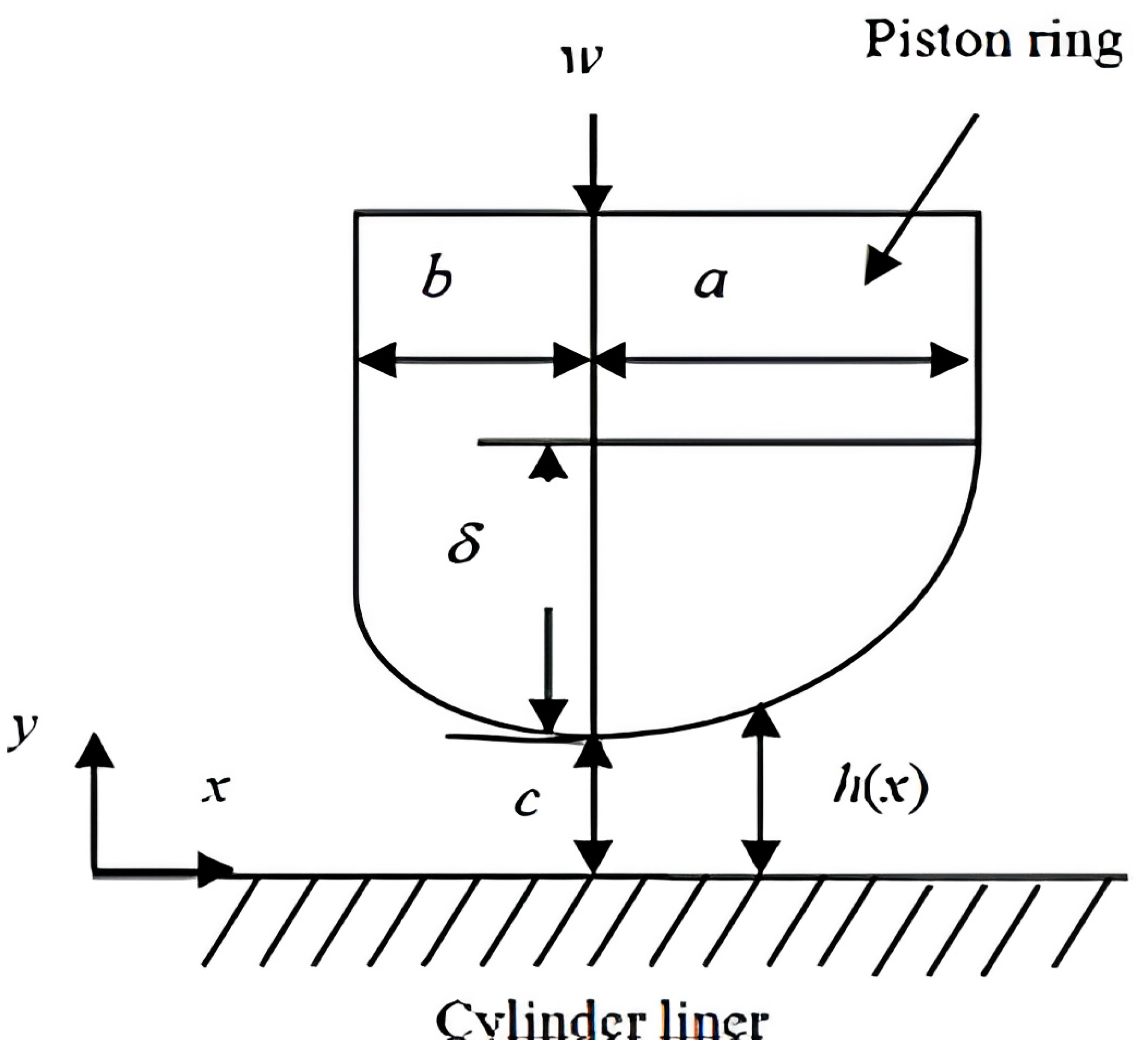
2.1. Piston Ring Geometry

A piston ring is a ring that is used to control the oil flow and compression in the engine. These rings are made from cast iron, ductile iron or steel with a plating of chrome, moly inlay, nitride, or physical vapor deposition (PVD). Figure 1 shows the geometry of piston rings located on the piston skirt, with an explanation of various terms in Figure 2. The ring free radius (RF) is the radius of the piston ring when it is fitted loosely on the engine bore. The nominal radius of the piston ring (RT) is its size when compressed to the actual bore size. The free gap refers to the end clearance between the sides of the ring when it is in its free state. A compressed gap (ENDGAP) is the same clearance when the ring is compressed to the bore size.
A fully coupled model for the motion deformation and lubrication features of the piston–ring–liner system has been proposed [29]. Dynamic responses of cylinder liners by finite-element modelling were carried out to study the combustion shock and piston side thrust force [30]. A good correlation was found between the numerical predictions and the measured vibration signals [30]. The dynamic deformation of the liner surface was obtained by finite element meshing (FEM)-based dynamic simulation [30]. To avoid changing modal characteristics of the cylinder liner caused by improper constraints, the joints and clearances were modelled through constructing a series of frictionless contact pairs, to avoid the errors induced by over-simplification and inappropriate mathematical equivalents. Sixteen simulated and measured mode frequencies of the cylinder liner were compared and the error was less than 4%. A comprehensive study has highlighted the relation between the piston skirt/liner lubrication and piston dynamics and slap [31]. The piston was modeled as a 3D body that collides with the liner as in a real engine. The goal was to investigate the piston slap force and subsequent liner vibration. A model for nonlinear multi-body flexible dynamic motion for a piston, connecting rod, crank pin, and liner was developed [32]. Totaro et al. [33] introduced a new piston skirt profile to reduce the engine friction [33]. The effects of formation of tribochemical films, was studied [34]. Experiments were carried out using polyalphaolefin as the base oil, mixed with different additives. It was found that dimples were interfering in the formation of tribochemical films. Comparative studies on the friction coefficients, worn surface features, and oil film characteristics were performed to check the performance of the cylinder liner–piston ring (CLPR) with the different surface textures in marine diesel [35]. The influence of the cylinder wall temperature and surface roughness on friction and wear was investigated [36]. An engine cylinder liner–piston ring tribotester was used to investigate the tribological properties of a cylinder liner–piston ring [37]. The main wear mechanisms were identified as corrosive wear and abrasive wear. Rectangular surface pockets were found to be effective in reducing friction in a piston–liner-type contact, providing that they are oriented with their long axis transverse to the sliding direction [38].
An elastohydrodynamic cavitation algorithm was developed for piston ring lubrication [39]. The load, sliding speed, and sliding distance of piston were taken into account to optimize the wear parameter of the Gray Cast Iron piston by Taguchi’s Design of Experiments technique by an analysis of the signal-to-noise ratio and an analysis of variance (ANOVA) [40]. A load of 45 N with a sliding speed of 1.5 m/s was used for the simulation with a piston sliding distance of 300 m to predict the specific wear rate.

2.2. Motion Formulation

Various results available on the piston ring–cylinder liner friction model, asperity contact model, and hydrodynamic lubrication between the piston ring and cylinder liner were taken into account in the presented study [41].
The axial position ( x ), speed ( U ), and acceleration ( a ) of the piston with respect to the liner, the angular position of the crankshaft ( θ ), measured from the top dead center (TDC), is given as [41]:
x = R cos θ + R 1 R L 2 sin 2 θ
U = d x d t = R ω sin θ + R 2 L sin 2 θ 1 R L 2 sin 2 θ
a = d 2 x d t 2 = R ω 2 cos θ + R L cos 2 θ + R L sin 4 θ 1 R L 2 sin 2 θ 3 / 2
where t is time, ω is the angular velocity of the crank, L is the length of the connecting rod, and R is the crank radius.
Figure 3 shows the dynamic oil lubrication between the ring and liner surface, where w is the radial force (N), a is the width of the parabolic portion of the ring face, b is the width of the straight portion of the ring face, δ is the inclination of the wedge, and c is the minimum film thickness.
The one-dimensional Reynolds equation to find the oil film pressure is given as follows [42]:
6 U η h x + 12 η d h d t = x h 3 P x
where P is the oil film pressure, η is the oil viscosity, U is the piston velocity, and h is the oil film thickness formed. The variation in oil film thickness with time is given as follows:
h x , t = h p x + h r t + a t . x
where h p is the profile height of the ring and hf is the reference distance of the ring.
The gas pressure developed inside the combustion chamber was simulated by taking into account the following assumptions:
  • The force of friction between the rings and the liner included the fluid friction as well as contact friction given by the lubricant shear friction given as well as the friction due to the contact given by the Greenwood–Tripp model;
  • The hydrodynamic oil film pressure developed was solved by using the Reynolds equation;
  • The force of friction was maximum at mid-stroke when the speed of the piston was the maximum;
  • Hydrodynamic lubrication was considered with the formation of full oil film thickness.
Figure 4 shows the force balance acting on a single piston ring. The axial motion of the piston ring is given by the system of equilibrium as follows [42]:
F b e n d i n g + F i n e r t i a , a x + F f r i c , a x + F g a s , a x = m r i n g d 2 y r i n g d t 2
where:
m r i n g : the ring mass;
y r i n g : the displacement of the ring with respect to the piston;
F g a s , a x : the gas force;
F i n e r t i a , a x : the inertia force;
F f r i c , a x : the friction force between the cylinder wall and ring running surface;
F b e n d i n g : the bending force caused by the interaction between the thrust and anti-thrust sides.
Figure 4. Force system in rings [25].
Lubricants 12 00427 g004
The radial motion of the piston ring is given as follows [42]:
F t e n s i o n + F h y d r o , r a d + F f r i c , r a d + F g a s , r a d = m r i n g d 2 x C G d t 2
where F h y d r o , r a d is the oil damping force and x C G is the location of the center of gravity of the ring.
In this article, our main aim was to study the effect of various engine operational parameters on the piston friction features in order to optimize the ring-profile-type reducing power losses. The model adopted for this purpose has been described in detail by Brahim Menacer and Mostefa Bouchetara [42].

3. Materials and Methods

A single-cylinder diesel engine with specifications seen in Table 1 was used in this numerical simulation study. SAE 30W was used as a lubricant in the engine, having properties as seen in Table 2. The engine was run at full load under 2000 RPM speed.
Engine data is as follows:
Manufacturer name: Iran khodro diesel IKAP, and production company (APCO). Téhéran city, Iran.
  • Type: 1.5 L EFD diesel engine 4stroke, 4cylinder in line SOHC.
  • Engine management: Sequential multi-point injection with PCM control unit.
  • Displacement: 1497 cm3
  • Bore: 76.0 mm
  • Stroke: 82.5 mm
  • Connecting Rod Length: 137 mm
  • Compression Ratio: 16.5:1
  • Max power/liter: 60 kW/lit
  • Max torque: 256 N·m
GT-Power is a powerful tool developed by Gamma Technologies for simulation of system of an internal combustion engine. A 1D model of GT-Power was proposed to study the effect of compression ratio on the specific fuel consumption [43]. A computational fluid dynamics (CFD) engine model was developed to study the variation on vehicle CO2 for regulatory cycle [44]. The 0D numerical simulations were performed by GT suite, for 30 different drive cycles with GPS-based vehicle speed information, for US as well as European Union (EU) [45]. Transient simulations were performed for power electric models and controller [46]. A turbocharged engine was modeled in GT-SUITE to study the effects of turbocharger casing heat losses on the catalyst warm-up [47]. Optimization of the heating, ventilation, and air conditioning (HVAC) system was carried out with an aim to achieve the best air quality, maintaining thermal comfort and minimizing the energy costs [48]. Development of a simulation model in GT-SUITE was carried out for the entire EV with introduction of a gain-scheduling PI control for temperature management [49]. A 1-dimensional model was developed for an electric vehicle (EV) to study the power of motor, charging of the battery, speed of vehicle, distance travelled, and energy consumption [50]. A correlation coefficient index (CI) was proposed in order to predict the battery energy consumption [50].
The numerical simulation was carried out by the GT-SUITE simulation software, as illustrated in Figure 5 above on an engine having specifications as shown in Table 1. The simulation algorithm shown in Figure 6 was established by considering piston velocity, gas chamber pressure, and lubrication conditions, as well as viscosity of lubricant. The Reynolds equation was solved using the finite difference method with boundary conditions.

3.1. Asperity Contact Model

Understanding the model of interaction between two mating surfaces is of critical importance to analyzing different engineering applications. These contact models are based on topography and properties of materials. The surface topography can be experimentally verified using optical and stylus profile meter as well as atomic force microscope. A statical method was used to analyze surface topography of a 3D isotropic rough surface [51].
Standard deviation of asperity heights is known as Sigma ( σ ). The ratio h / σ (where h is the separation between the surfaces) determines the presence and level of metal-to-metal (asperity) normal and friction forces at the contact. Sigma can be approximated from R q (root mean square roughness)* as σ 0.7 × R a R q can be approximated from Ra (arithmetic average roughness) as follows:
R q 1.11 × R a   ( ideal   sine   wave )
R q 1.25 × R a   ( polished surfaces )
R q 1.45 × R a   is   ( raw   honed   surfaces ) taken   into   account   in   this   research   paper .

3.2. Greenwood–Tripp Asperity Interaction Model

The Greenwood–Tripp model assumes a Gaussian distribution of the actual surface points about a mean, nominal surface. The surface is described by the standard deviation about this mean, and also by an asperity density (number of asperities per unit area) and the average radius of curvature of asperity tops, assumed to be locally spherical.
This is calculated by summing the force required to elastically deform the portion of asperities (in a unit area) that would interfere; for a given nominal clearance between the two contacting surfaces, the effective asperity contact pressure is given as follows:
P c = 16 2 π 15 σ × β × η 2 E * σ β f 5 / 2 λ
Force function F is given as follows:
F x = 2 π x s x 2 5 exp s 2 2
where:
β is asperity radius of curvature ( β = β 1 + β 2 );
1 and 2 denote the two surfaces in nominal contact.;
σ is the composite surface standard deviation ( σ = σ 1 2 + σ 2 2 );
η is the asperity density ( η = η 1 + η 2 );
E is composite elastic modulus of materials in contact.
E = 1 1 υ 1 2 E 1 + 1 υ 2 2 E 2
where h is nominal distance between two contacting surfaces.

4. Results and Discussion

In order to validate the proposed mathematical model developed in the current study, and, hence, achieve reliability, a comparative analysis was carried out between the gas pressure results generated by the presented model and the values generated from experimental tests by running the engine at 2000 RPM under a partial load [52,53], as shown in Figure 7. A high correlation was found between the two datasets, with an approximate error margin of only 3%.

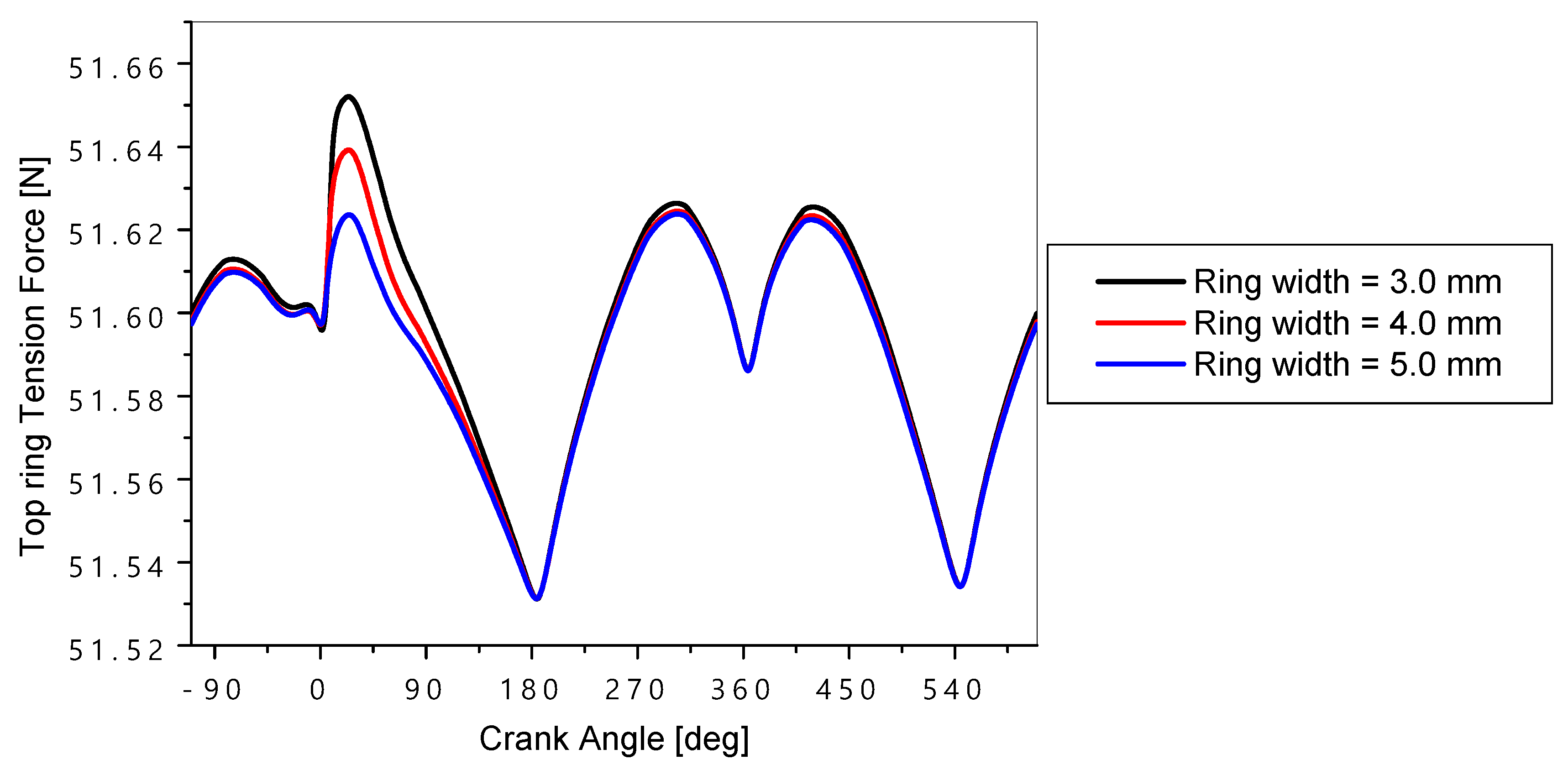
4.1. Effect of the Top Ring Width

The top ring thickness plays a crucial role in studying the hydrodynamic behavior of an internal combustion engine as shown in the results presented in Figure 8, Figure 9, Figure 10, Figure 11, Figure 12 and Figure 13.
In Figure 8, it was observed that the thicker ring exerts more pressure on the oil film, which can cause a decrease in the minimum film thickness, thus increasing the risk of metal-to-metal contact and accelerated wear. In Figure 9 and Figure 10, it can be observed that the maximum values of hydrodynamic friction and hydrodynamic power decreased with an increase in the thickness of the top ring. This is because a greater thickness provided a more stable support, resulting in a better distribution of the load. However, it reduced the friction force and hydrodynamic power losses. The top ring thickness had a significant effect on the ring twisting angle, the tension force in the top ring, and the maximum oil pressure (Figure 11, Figure 12 and Figure 13). If the top ring thickness was increased by 2 mm (from 3 mm to 5 mm), then the maximum oil film thickness increased by 15%, the hydrodynamic friction force decreased by 2%, the hydrodynamic friction power loss decreased by 4%, the top ring twist angle decreased by 5%, the top ring tension force decreased by 10%, and the ring oil pressure decreased by 5%.

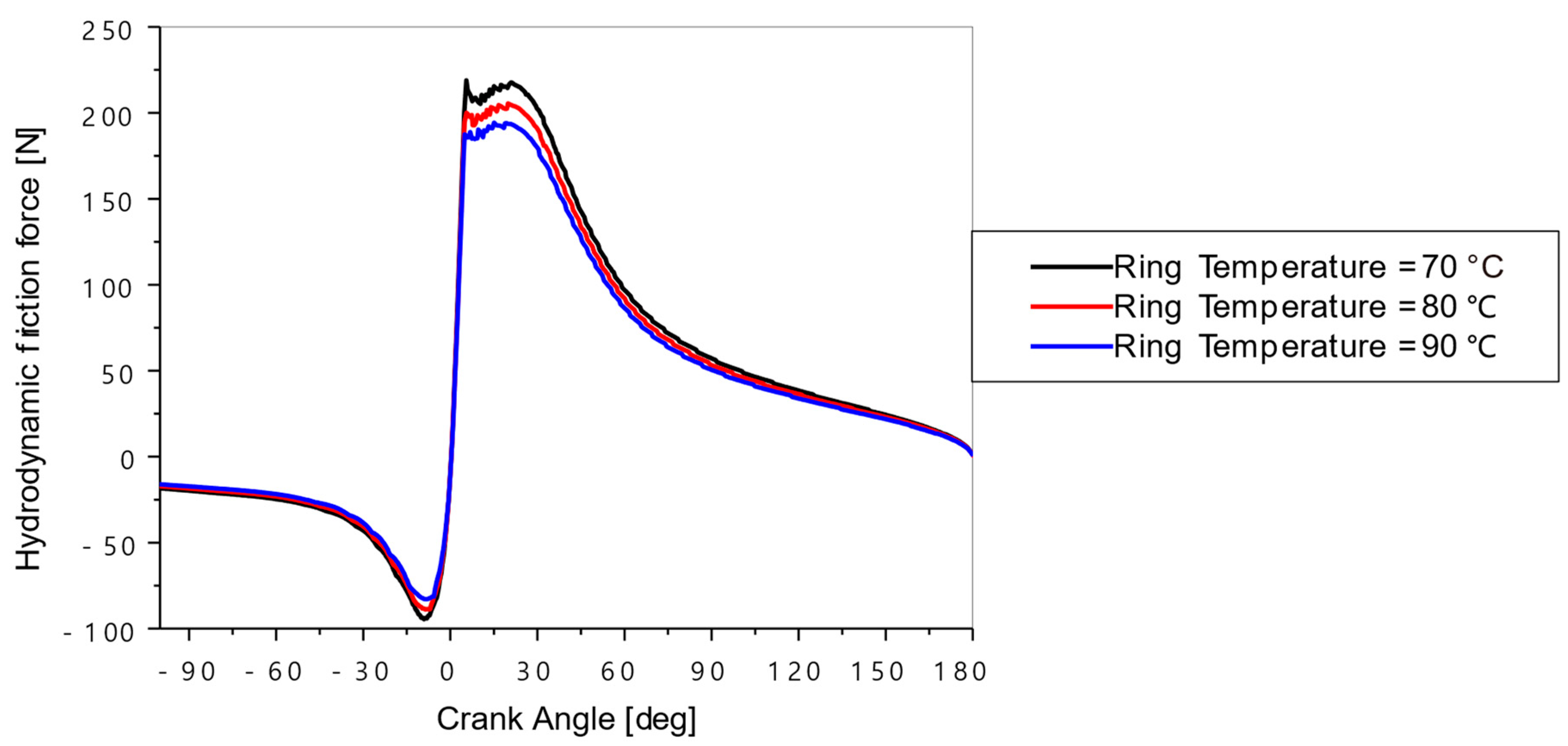
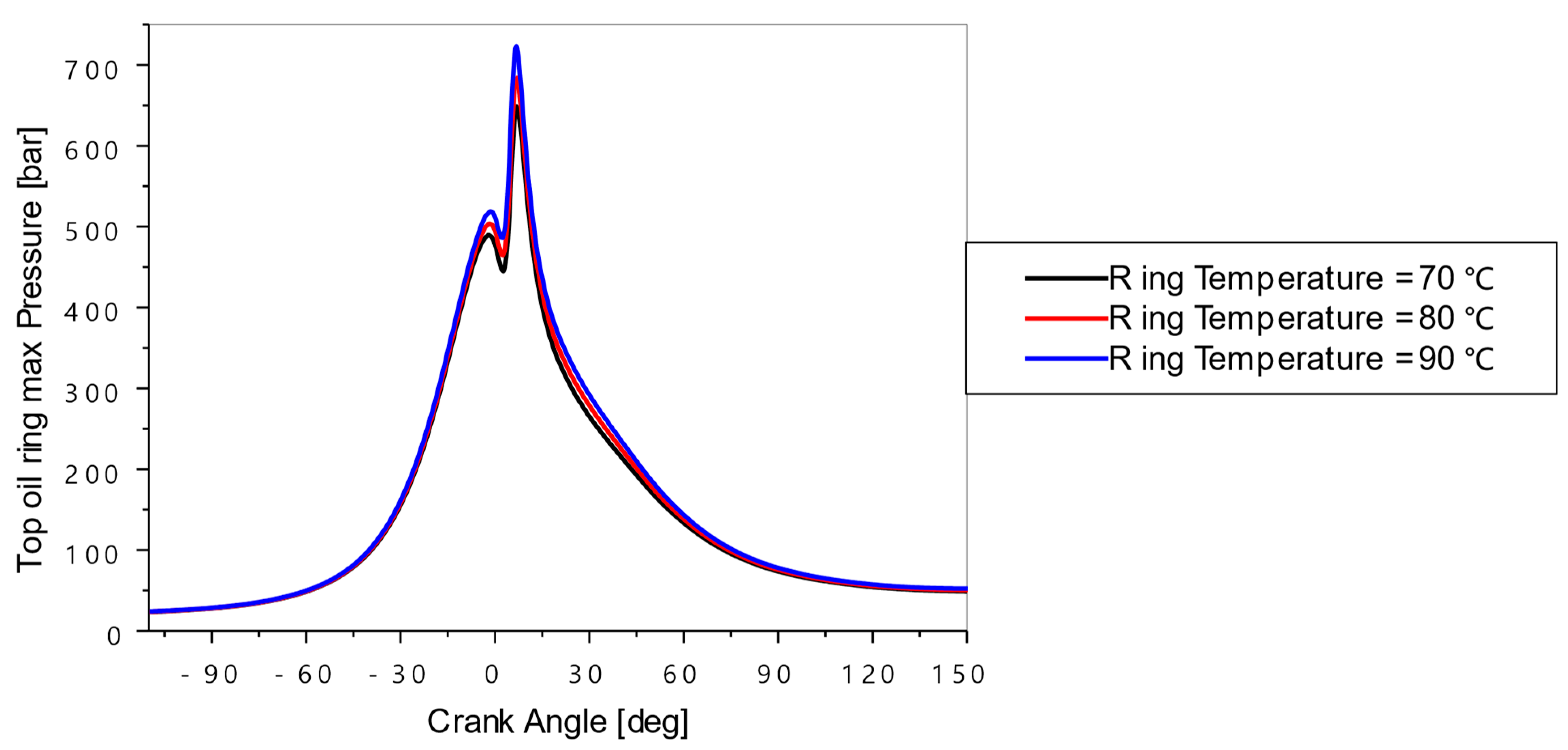
4.2. Effect of the Top Ring Temperature

The top ring temperature plays a crucial role in the lubrication performance of an internal combustion engine. Figure 14, Figure 15, Figure 16, Figure 17 and Figure 18 show the evolution of the oil film thickness, hydrodynamic friction force, hydrodynamic friction power loss, top ring twist angle, and oil pressure in the cylinder as a function of the crankshaft angle for different top ring temperatures (70 °C, 80 °C, and 90 °C). The engine was operated under a speed of 2000 RPM and under partial load conditions. During the combustion phase, the top ring was subjected to higher temperatures, which directly affected the oil viscosity and the oil film thickness (see Figure 14). The maximum values of the oil film thickness increased with the top ring temperature. This is explained by the fact that the viscosity of the oil decreased as the top ring temperature increases, making the oil more viscous.
Figure 15 and Figure 16 show that the effect of the top ring temperature was particularly marked during the ignition and expansion periods of the engine cycle. The hydrodynamic friction force and the power losses decreased with a rise in the top ring temperature. The decrease in oil viscosity, that was associated with a rise in the ring temperature, can reduce the oil’s ability to maintain sufficient hydrodynamic force, thereby increasing the risk of metallic contact. From Figure 17, the influence of the top ring temperature on the ring twist angle was found to be negligible. Finally, from the Figure 18, it can be observed that the pressure peak increased with a rise in the top ring temperature.

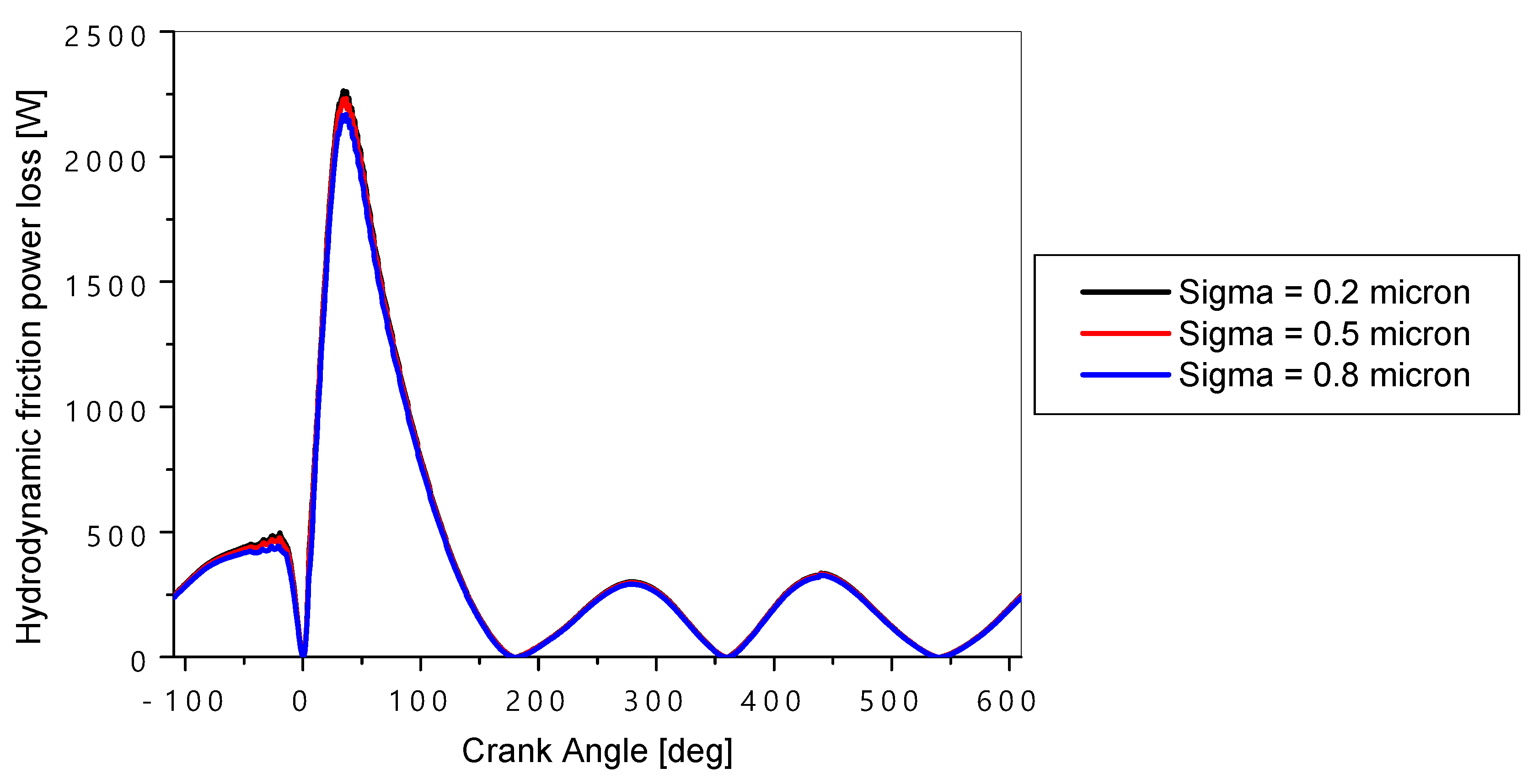
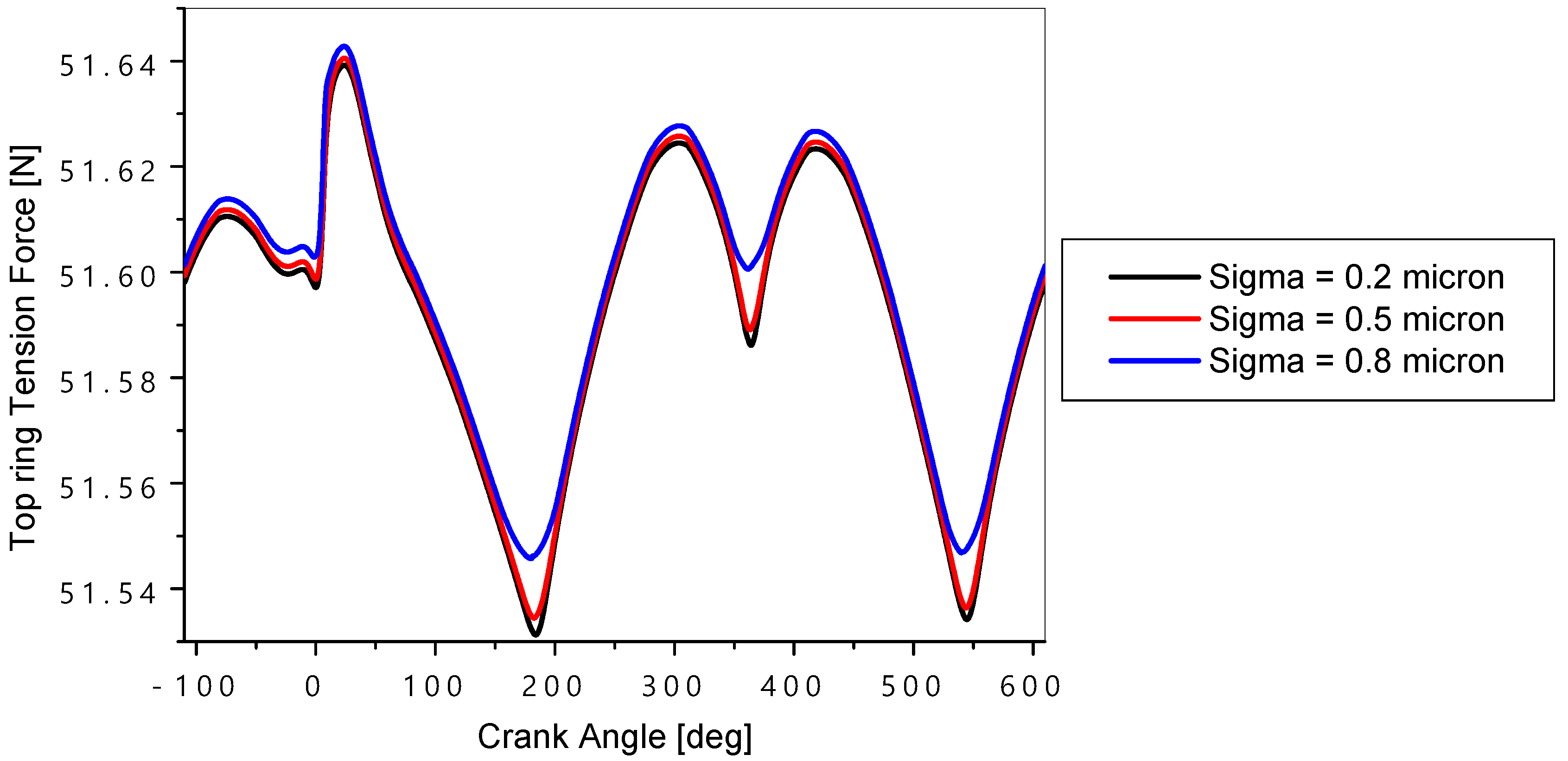
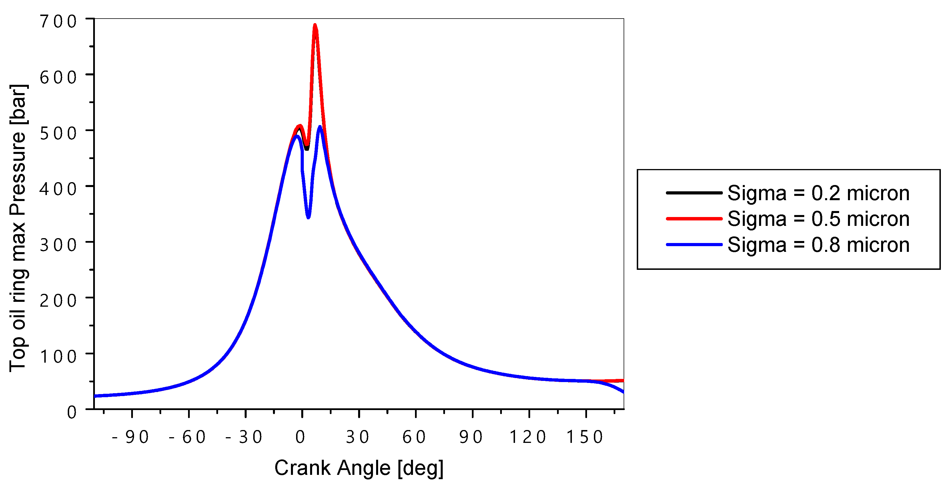
4.3. Effect of the Top Ring Surface Roughness

Figure 19, Figure 20, Figure 21, Figure 22, Figure 23 and Figure 24 show the effect of the surface roughness levels of the top ring (sigma = 0.2 micron, 0.5 micron, and 0.8 micron) on various hydrodynamic parameters of the engine. From Figure 19, it may be observed that the minimum oil film thickness between the top ring and the cylinder increased with an increase in the ring roughness, especially at dead center locations. The simulation code is almost matching with the work performed by Takiguchi et al. [2]. From Figure 20, it can be seen that, at higher ring roughness values, the peaks of the asperities could bear most of the load, leading to increased wear and higher contact forces. From Figure 21, it can be observed that the hydrodynamic friction power losses can increase with the roughness, as the oil film was less stable. From Figure 22, it can be observed that the ring roughness has a very limited effect on the ring twist angle. However, in Figure 23 and Figure 24, the effect of the ring roughness on the ring tension it haforce and oil pressure was very noticeable, especially at the BDC for the ring tension force and during the combustion–expansion phase for the peak oil pressure value.

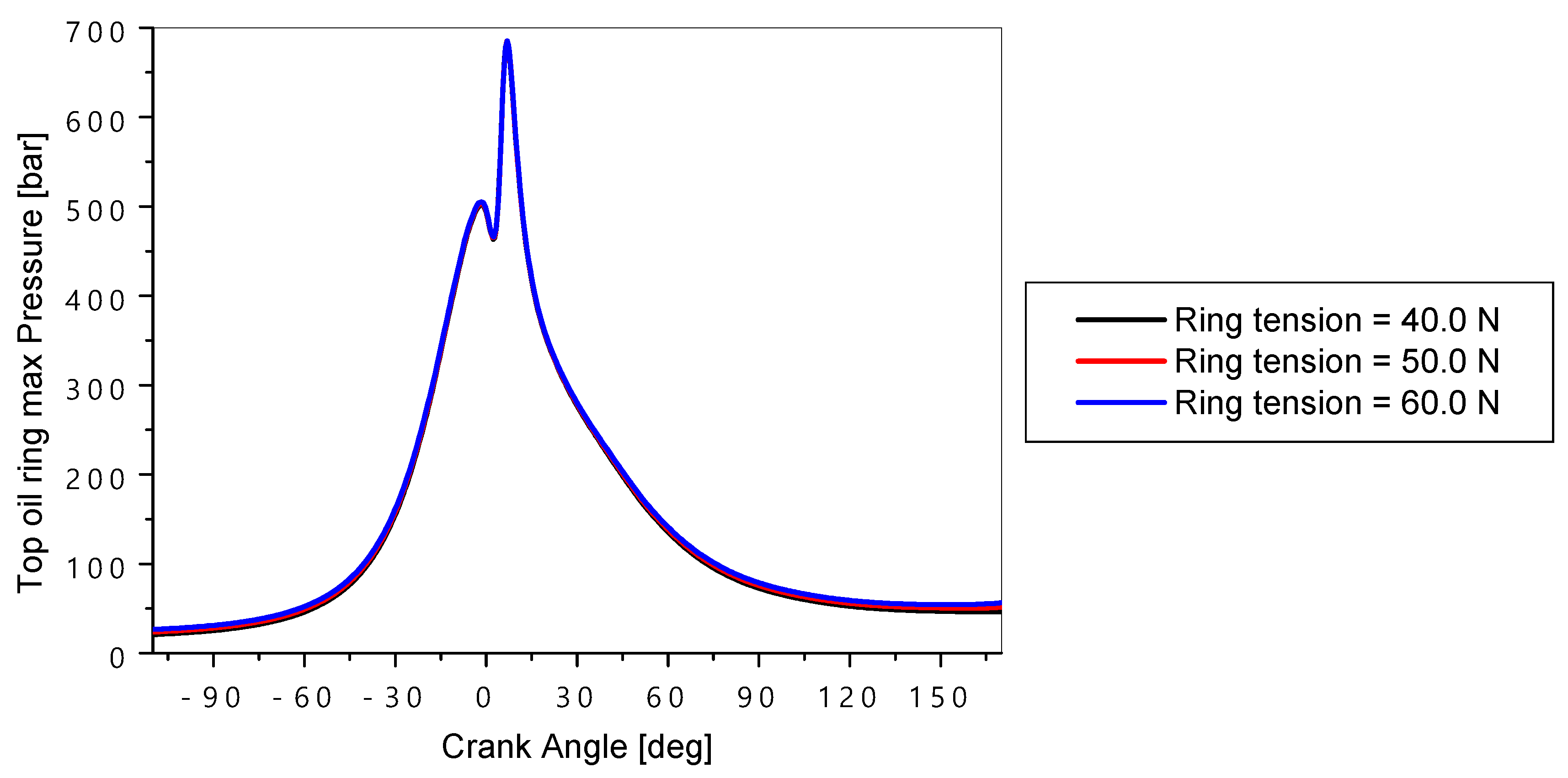
4.4. Effect of the Top Ring Tension

The top ring tension is another parameter that can influence the hydrodynamic performance of an engine. The variations in the lubrication oil parameters as a function of the crankshaft angle for different top ring tensions (40 N, 50 N, and 60 N) are presented, respectively, in Figure 25, Figure 26, Figure 27, Figure 28 and Figure 29.
According to Figure 25, the ring tension had the least effect on the oil film thickness during the expansion phase. Higher tension in the rings causes more compression in the oil film, especially during the expansion stroke of the engine cycle. From Figure 26, it can be seen that, when the ring tension is high, the maximum hydrodynamic frictions force increased slightly, leading to a greater resistance to the sliding motion between the top ring and the cylinder. This can reduce the lifespan of the segments and the cylinder. From Figure 27, it can be seen that the top ring tension increased the hydrodynamic power required to maintain the oil film, particularly during the compression and explosion phases of the engine cycle. Finally, Figure 28 and Figure 29 show that the impact of the top ring tension on the ring twist angle and the oil pressure was relatively negligible.
Further, various ring profiles were investigated, with the results shown in Figure 30 and Figure 31.
Figure 30 shows the different top ring profiles used in the study. The cylindrical profile of the ring provides better lubrication conditions with less axial contact to the liner surface which improves sealing.
Figure 31 presents the variations in the friction coefficient with various ring profile types for an engine speed of 1000 and 2000 RPM. The friction coefficient was found to be the maximum for the type 1 profile and the minimum for the type 3 ring. The reason for the minimum friction coefficient for the type 3 ring was the minimum force acting between the ring and the cylinder liner.

5. Conclusions

This article examined the effect of the top ring design on the hydrodynamic lubrication in internal combustion engines using GT-SUITE software. Key factors like the width and temperature of top ring, surface roughness, and top ring tension were analyzed. The results showed that these parameters significantly influence the hydrodynamic behavior of the system. The following are the key conclusions from this work:
During the combustion relation period, an increase in the top ring thickness tends to reduce the minimum film thickness. This may even contribute to poor surface separation and increased metal-to-metal contact. However, this increase in the oil film may reduce the hydrodynamic friction force.
Higher temperatures tend to reduce the oil film thickness due to the reduction in the oil viscosity, hence increasing the risk of direct contact between surfaces. However, this increase in temperature also reduces the hydrodynamic friction force.
An increase in the roughness tends to disrupt the continuity in the oil film, which can lead to reduced lubrication efficiency. On the other hand, some roughness can also improve oil film adhesion, suggesting that optimizing the roughness could be a key parameter for the stability of lubrication film.
Higher tension in the top ring reduces the minimum oil film thickness, and can thus help to achieve a twist angle that favors the uniform distribution of the oil film.
These results discussed above highlight the fact that it is possible to optimize the hydrodynamic performance by varying various top ring parameters. However, the results presented have some limitations. Various assumptions used for the simplification of models may not cover all real-time operating conditions, particularly seen during operations under extreme environments. In addition, the complex interaction may require further analysis with nonlinear models and advanced numerical simulations to better capture reality.
In conclusion, we suggest that future work could focus on the combined influence of complex dynamic configurations, such as real-time engine speed and load changes. The study of alternative materials with different thermal and roughness properties could also offer new prospects for improving the hydrodynamic performance.
For future work, we will try to introduce new mathematical models based on pressure and flow conditions by involving the surface roughness effects for a better understanding of lubrication regimes. Particular focus will be on the piston ring dynamics, possible contact pressures between different rings, and mass flows.

Author Contributions

Conceptualization, J.S., T.K., M.U.K., B.M., S.N., and V.T.; methodology, T.K., M.U.K., and S.A.; formal analysis, S.A., M.U.K., S.N., L.O., A.O., and V.T.; investigation, M.U.K.; resources, M.U.K. and S.A.; writing—original draft preparation M.U.K., S.N., V.T., and B.M.; writing—review and editing, S.A., S.N., L.O., A.O., V.T., and B.M.; visualization, V.T., I.G., and N.S.; supervision, V.T., S.N., I.G., and N.S. All authors have read and agreed to the published version of the manuscript.

Funding

This research received no external funding.

Data Availability Statement

Data sharing is not applicable to this article as no datasets were generated or analyzed during the current study.

Conflicts of Interest

The authors declare no conflicts of interest.

References

  1. Knauder, C.; Allmaier, H.; Sander, D.E.; Sams, T. Investigations of the Friction Losses of Different Engine Concepts: Part 3: Friction Reduction Potentials and Risk Assessment at the Sub-Assembly Level. Lubricants 2020, 8, 39. [Google Scholar] [CrossRef]
  2. Xiuyi, L.; Jiao, B.; Lu, X.; Zou, D.; Ma, X.; Neville, A. A statistical piston ring lubrication model considering the tribofilm and its effect of two-stroke marine engines. Tribol. Int. 2023, 177, 107996. [Google Scholar] [CrossRef]
  3. Forero, J.D.; Ochoa, G.V.; Rojas, J.P. Effect of the Geometric Profile of Top Ring on the Tribological Characteristics of a Low-Displacement Diesel Engine. Lubricants 2020, 8, 83. [Google Scholar] [CrossRef]
  4. Liu, L. Modeling the Performance of the Piston Ring-Pack with Consideration of Non-Axisymmetric Characteristics of the Power Cylinder System in Internal Combustion Engines. Ph.D. Thesis, Massachusetts Institute of Technology, Cambridge, MA, USA, 2000. [Google Scholar]
  5. Dickinson, M.W. Dynamic Modelling of Compression Ring Conformability in High Performance Engines. Ph.D. Thesis, University of Central Lancashire, Preston, UK, 2016. [Google Scholar]
  6. Rao, X.; Sheng, C.; Guo, Z.; Zhang, X.; Yin, H.; Xu, C.; Yuan, C. Effects of textured cylinder liner piston ring on performances of diesel engine under hot engine tests. Renew. Sustain. Energy Rev. 2021, 146, 111193. [Google Scholar] [CrossRef]
  7. Gussmagg, J.; Maier, M.; Pusterhofer, M.; Grün, F. EHD simulation study on the influence of measured ICE compression piston ring profiles on the lubrication film formation. Tribol. Int. 2024, 199, 110015. [Google Scholar] [CrossRef]
  8. Wolff, A.; Koszalka, G. Influence of engine load on piston ring pack operation of an automotive IC engine. Combust. Engines 2022, 190, 88–94. [Google Scholar] [CrossRef]
  9. Ali, M.K.A.; Hou, X.; Turkson, R.F.; Ezzat, M. An analytical study of tribological parameters between piston ring and cylinder liner in internal combustion engines. Proc. Inst. Mech. Eng. Part K-J. Multi-Body Dyn. 2016, 230, 329–349. [Google Scholar] [CrossRef]
  10. Liu, N.; Wang, C.; Xia, Q.; Gao, Y.; Liu, P. Simulation on the effect of cylinder liner and piston ring surface roughness on friction performance. Mech. Ind. 2022, 23, 8. [Google Scholar] [CrossRef]
  11. Zhang, J.; Guo, S.; Xiong, P.; Li, Y.; Sun, W.; Deng, L. Effects of the Piston Skirt’s Surface Structure on Coating Quality and Friction Functions. Coatings 2024, 14, 1385. [Google Scholar] [CrossRef]
  12. Krakowski, R.; Marut, T. The Effect of Ecological Agents Added to Lubricating Oil on Selected Operating Parameters of an Internal Combustion Engine. Energies 2023, 16, 7510. [Google Scholar] [CrossRef]
  13. Edtmayer, J.; Lösch, S.; Hick, H.; Walch, S. Comparative study on the friction behaviour of piston/bore interface technologies. Automot. Engine Technol. 2019, 4, 101–109. [Google Scholar] [CrossRef]
  14. Kang, J.; Cho, J.; Park, S. Investigation of Friction Loss Characteristics of Engine Pistons for Different Engine Operating Conditions. Int. J. Automot. Technol. 2023, 24, 503–511. [Google Scholar] [CrossRef]
  15. Michelberger, B.; Jaitner, D.; Hagel, A.; Striemann, P.; Kröger, B.; Wetzel, F.-J.; Leson, A.; Lasagni, A.F. Friction Response of Piston Rings for Application-like Starvation and Benefit of Amorphous Carbon Coatings. Coatings 2022, 12, 738. [Google Scholar] [CrossRef]
  16. Dlugoš, J.; Novotný, P. Effective Implementation of Elastohydrodynamic Lubrication of Rough Surfaces into Multibody Dynamics Software. Appl. Sci. 2021, 11, 1488. [Google Scholar] [CrossRef]
  17. Ge, C.; Zhang, B.; Xu, X.; Lyu, X.; Ma, X.; Li, T.; Lu, X.; Liu, Z. Tribofilm distribution and tribological analysis of piston ring-cylinder liner interfaces under realistic engine conditions. Tribol. Int. 2025, 201, 110250. [Google Scholar] [CrossRef]
  18. Li, Z.; Han, X.; Shan, Y.; Shen, Y.; Xu, J. The effect of MoS2 concentration on the thickness and tribology performance of electro-codeposited Ni–Cr–MoS2 coatings. Wear 2024, 552–553, 205457. [Google Scholar] [CrossRef]
  19. Sanadhya, K.; Malkhede, D.N.; Nandgaonkar, M.R.; Aghav, Y.V.; Kumar, M.N. Effect of Piston Profile on Piston Motion and Liner Bore Polishing. Int. J. Automot. Technol. 2024, 25, 225–233. [Google Scholar] [CrossRef]
  20. Liu, S.; Gao, L.; Xing, M.; Cui, Y.; Meng, X. A new 3-D multi-physics coupling model for lubricated piston-liner systems. Int. J. Mech. Sci. 2024, 272, 109194. [Google Scholar] [CrossRef]
  21. Zhang, B.; Ma, X.; Liu, L.; Wang, Y.; Yu, H.; Morina, A.; Lu, X. Reciprocating sliding friction behavior and wear state transition mechanism of cylinder liner and piston ring. Wear 2024, 546-547, 205293. [Google Scholar] [CrossRef]
  22. Guo, P.; Yan, Z.; Xu, J.; Shen, Y.; Wang, J. Wear life prediction of piston ring and cylinder liner based on integration of experiment and bench test data. Eng. Fail. Anal. 2024, 161, 108259. [Google Scholar] [CrossRef]
  23. Kanemoto, K.; Ito, A. A study on the effect of factors of piston motion on the piston ring rotation of an engine. Tribol. Int. 2024, 194, 109483. [Google Scholar] [CrossRef]
  24. García-Rodiño, D.; Blanco-Rodríguez, J.; Cortada-García, M.; Fernández, S.; Porteiro, J. A numerical procedure for calculating roughness parameters for the Greenwood-Tripp model of asperity contact based on 3D measurements. Tribol. Int. 2024, 200, 110156. [Google Scholar] [CrossRef]
  25. Shah, A.S.; Bhatt, D.V. Experimental Study to Measure Piston Ring Assembly Friction of Multicylinder I.C. Engine (S.I.) on Motorized Engine Test Rig: A Case Study. In Proceedings of International Conference on Advances in Tribology and Engineering Systems. Lecture Notes in Mechanical Engineering; Patel, H., Deheri, G., Patel, H., Mehta, S., Eds.; Springer: Berlin/Heidelberg, Germany, 2014. [Google Scholar]
  26. Liu, C.; Lu, Y.-J.; Zhang, Y.-F.; Li, S.; Müller, N. Numerical study on the lubrication performance of compression ring-cylinder liner system with spherical dimples. PLOS ONE 2017, 12, e0181574. [Google Scholar] [CrossRef]
  27. Liu, C.; Lu, Y.; Zhang, Y.; Li, S.; Kang, J.; Müller, N. Numerical Study on the Tribological Performance of Ring/Liner System With Consideration of Oil Transport. J. Tribol. 2019, 141, 011701. [Google Scholar] [CrossRef]
  28. Hei, D.; Zheng, M.; Liu, C.; Jiang, L.; Zhang, Y.; Zhao, X. Study on the frictional properties of the top ring-liner conjunction for different-viscosity lubricant. Adv. Mech. Eng. 2023, 15. [Google Scholar] [CrossRef]
  29. Lining, G.; Yi, C.; Zhaohui, X.; Yan, F.; Shuo, L.; Yafen, L.; Xinrong, H. A fully coupled tribo-dynamic model for piston-ring-liner system. Tribol. Int. 2023, 178, 107998. [Google Scholar] [CrossRef]
  30. Li, G.; Gu, F.; Wang, T.; Yang, T.; Ball, A. Investigation into the dynamic response of cylinder liners in an IC engine based on a validated finite-element model. Syst. Sci. Control Eng. 2017, 5, 56–69. [Google Scholar] [CrossRef]
  31. Delprete, C.; Razavykia, A. Piston dynamics, lubrication and tribological performance evaluation: A review. Int. J. Engine Res. 2020, 21, 725–741. [Google Scholar] [CrossRef]
  32. Chowdhury, S. Cylinder Liner Velocity Calculation under Dynamic Condition in the Pursuit of Liner Cavitation Investigation of an Internal Combustion Engine. SAE Int. J. Engines 2024, 17, 309–320. [Google Scholar] [CrossRef]
  33. Totaro, P.P.; Westerfield, Z.; Tian, T. Introducing a New Piston Skirt Profile to Reduce Engine Friction; SAE Paper No. 2016-01-1046; SAE: Warrendale, PA, USA, 2016. [Google Scholar]
  34. Mishra, P.; Ramkumar, P. Effect of additives on a surface textured piston ring–cylinder liner system. Tribol.-Mater. Surfaces Interfaces 2019, 13, 67–75. [Google Scholar] [CrossRef]
  35. Rao, X.; Sheng, C.; Guo, Z.; Yuan, C. Influence of Surface Groove Width on Tribological Performance for Cylinder Liner–Piston Ring Components. Tribol. Trans. 2019, 62, 239–248. [Google Scholar] [CrossRef]
  36. Ma, Z.; Henein, N.A.; Bryzik, W. A Model for Wear and Friction in Cylinder Liners and Piston Rings. Tribol. Trans. 2006, 49, 315–327. [Google Scholar] [CrossRef]
  37. Xu, Y.F.; Yu, H.Q.; Wei, X.Y.; Cui, Z.; Hu, X.G.; Xue, T.; Zhang, D.Y. Friction and Wear Behaviors of a Cylinder Liner–Piston Ring with Emulsified Bio-Oil as Fuel. Tribol. Trans. 2013, 56, 359–365. [Google Scholar] [CrossRef]
  38. Vlădescu, S.-C.; Ciniero, A.; Tufail, K.; Gangopadhyay, A.; Reddyhoff, T. Optimization of Pocket Geometry for Friction Reduction in Piston–Liner Contacts. Tribol. Trans. 2017, 61, 522–531. [Google Scholar] [CrossRef]
  39. Yang, Q.; Keith, T.G. Two-Dimensional Piston Ring Lubrication—Part I: Rigid Ring and Liner Solution. Tribol. Trans. 1996, 39, 757–768. [Google Scholar] [CrossRef]
  40. Ananth, S.; Sivanesh, A.R.; Prakash, J.U.; Paul, P.J. Wear parameter optimisation of piston and cylinder liner material (GCI) using Taguchi technique. Int. J. Ambient. Energy 2019, 43, 783–787. [Google Scholar] [CrossRef]
  41. Kunt, M.A.; Calam, A.; Gunes, H. Analysis of the effects of lubricating oil viscosity and engine speed on piston-cylinder liner frictions in a single cylinder HCCI engine by GT-SUITE program. Proc. Inst. Mech. Eng. Part E: J. Process. Mech. Eng. 2022, 237, 399–409. [Google Scholar] [CrossRef]
  42. Menacer, B.; Bouchetara, M. The compression ring profile influence on hydrodynamic performance of the lubricant in diesel engine. Adv. Mech. Eng. 2014, 12, 1–13. [Google Scholar] [CrossRef]
  43. Assis, M.S.S.; de Castro, D.H.; Moreira, T.A.A.; Filho, F.A.R.; Malaquias, A.C.T.; Baêta, J.G.C. Numerical Study of Compression Ratio Influence on Specific Fuel Consumption of an Ethanol Fueled Engine Using GT POWER Code; SAE Technical Paper 2022-36-0075; SAE: Warrendale, PA, USA, 2023. [Google Scholar] [CrossRef]
  44. Kaushik, H.K.; Rani, A.; Sarna, N. Assessment of CNG & CBG Composition Variation on CO2 Emissions, Engine Performance and Durability for a Small Size PFI Engine; SAE Technical Paper 2022-28-0020; SAE: Warrendale, PA, USA, 2022. [Google Scholar] [CrossRef]
  45. Garcia, A.; Monsalve-Serrano, J.; Villalta, D.; Tripathi, S. Electric Vehicles vs e-Fuelled ICE Vehicles: Comparison of potentials for Life Cycle CO2 Emission Reduction; SAE Technical Paper 2022-01-0745; SAE: Warrendale, PA, USA, 2022. [Google Scholar] [CrossRef]
  46. Kumar, V.; Challa, K.; Banik, S.; Borado, P. Unified Thermal System Simulations of an Electric Truck. SAE Int. J. Adv. Curr. Pr. Mobil. 2023, 5, 1537–1543. [Google Scholar] [CrossRef]
  47. Ravikumar, A.; Bhatt, A.; Gainey, B.; Lawler, B. GT-Suite Modeling of Thermal Barrier Coatings in a Multi-Cylinder Turbocharged DISI Engine for Catalyst Light-Off Delay Improvement; SAE Technical Paper 2023-01-1602; SAE: Warrendale, PA, USA, 2023. [Google Scholar]
  48. Lesage, M.; Chalet, D.; Migaud, J.; Krautner, C. Optimization of air quality and energy consumption in the cabin of electric vehicles using system simulation. J. Environ. Manag. 2024, 358, 120861. [Google Scholar] [CrossRef]
  49. Narimani, M.; Emami, S.A.; Banazadeh, A.; Modarresi, A. A unified thermal management framework for electric vehicles: Design and test bench implementation. Appl. Therm. Eng. 2024, 248, 123057. [Google Scholar] [CrossRef]
  50. Nabi, N.; Ray, B.; Rashid, F.; Al Hussam, W.; Muyeen, S. Parametric analysis and prediction of energy consumption of electric vehicles using machine learning. J. Energy Storage 2023, 72, 108226. [Google Scholar] [CrossRef]
  51. Kalin, M.; Zugelj, B.; Lamut, M.; Hamouda, K. Elastic and plastic deformation of surface asperities and their load-carrying mechanisms during the formation of a real contact area. Tribol. Int. 2023, 178, 108067. [Google Scholar] [CrossRef]
  52. Esmaeil, T.; Kazerooni, R.B. Energy analysis and the comparison of gasoline direct injection engines performance parameters with port fuel injection engines. IOSR J. Mech. Civ. Eng. 2016, 13, 104–114. [Google Scholar] [CrossRef]
  53. Takiguchi, M.; Harigaya, Y.; Suzuki, M. Analysis of oil film thickness on a piston ring of diesel engine: Effect of oil film temperature. J. Eng. Gas Turbines Power 2003, 125, 596–603. [Google Scholar]
Figure 1. Position of ring on piston.
Lubricants 12 00427 g001
Figure 2. Definition of reference (nominal) radius (RT), reference ring tension (T), reference end gap (ENDGAP), and ring free radius (RF).
Lubricants 12 00427 g002
Figure 3. Lubrication model between the ring and the liner [42].
Lubricants 12 00427 g003
Figure 5. Piston–ring–cylinder liner model using GT-SUITE software [41].
Lubricants 12 00427 g005
Figure 6. Flow chart of simulation algorithm [41].
Lubricants 12 00427 g006
Figure 7. Simulated and experimental in-cylinder gas pressure as a function of crank angle.
Lubricants 12 00427 g007
Figure 8. Variation in oil film thickness with width of top ring.
Lubricants 12 00427 g008
Figure 9. Variation in hydrodynamic friction force with width of top ring.
Lubricants 12 00427 g009
Figure 10. Variation in hydrodynamic friction power losses with width of top ring.
Lubricants 12 00427 g010
Figure 11. Variation in twisting angle with width of top ring.
Lubricants 12 00427 g011
Figure 12. Variation in ring tension force with width of top ring.
Lubricants 12 00427 g012
Figure 13. Variation in oil cylinder pressure with width of top ring.
Lubricants 12 00427 g013
Figure 14. Variation in oil film thickness with temperature.
Lubricants 12 00427 g014
Figure 15. Variation in hydrodynamic friction forces with ring temperature of the top ring.
Lubricants 12 00427 g015
Figure 16. Variation in hydrodynamic friction power losses with temperature of the top ring.
Lubricants 12 00427 g016
Figure 17. Variation in the twisting angle with temperatures of the top ring.
Lubricants 12 00427 g017
Figure 18. Variation in oil film pressure with the width of top ring.
Lubricants 12 00427 g018
Figure 19. Variation in ring oil film thickness with ring surface roughness of the top ring.
Lubricants 12 00427 g019
Figure 20. Variation in ring hydrodynamic friction force with ring surface roughness of the top ring.
Lubricants 12 00427 g020
Figure 21. Variation in the ring hydrodynamic friction power losses with ring surface roughness.
Lubricants 12 00427 g021
Figure 22. Variation in the twisting in the top ring with the ring surface roughness.
Lubricants 12 00427 g022
Figure 23. Variation in the tension in the top ring with the ring surface roughness.
Lubricants 12 00427 g023
Figure 24. Variation in the oil ring pressure with ring surface roughness of the top ring.
Lubricants 12 00427 g024
Figure 25. Variation in oil film thickness with the tension in the top ring.
Lubricants 12 00427 g025
Figure 26. Variation in hydrodynamic friction force with the tension in the top ring.
Lubricants 12 00427 g026
Figure 27. Variation in hydrodynamic friction power losses with the tension in the top ring.
Lubricants 12 00427 g027
Figure 28. Variation in twisting angle with the tension in the top ring.
Lubricants 12 00427 g028
Figure 29. Variation in maximum lubrication oil film pressure formed with the tension in the top ring.
Lubricants 12 00427 g029
Figure 30. Investigated top ring profiles [42].
Lubricants 12 00427 g030
Figure 31. Friction coefficient versus ring type and engine speed [42].
Lubricants 12 00427 g031
Table 1. Specifications of test engine.
Engine speed2000RPM
Ring surface roughness0.10μm
Bore surface roughness 0.71μm
Oil density881.5Kg/m3
Oil viscosity0.0087Pa-s
Table 2. Specifications of SAE 30W at 40 °C.
Oil density860kg/m3
Oil viscosity064Centistoke
Disclaimer/Publisher’s Note: The statements, opinions and data contained in all publications are solely those of the individual author(s) and contributor(s) and not of MDPI and/or the editor(s). MDPI and/or the editor(s) disclaim responsibility for any injury to people or property resulting from any ideas, methods, instructions or products referred to in the content.

