1. Introduction
The titanium alloy Ti-6Al-4V, or Grade 5 titanium, has become one of the most commonly used metallic alloys in the aerospace industry [
1], owing in particular to its excellent strength-to-weight ratio [
2], corrosion-resistant properties, and its suitability for operation at elevated temperatures as high as 400 °C, making it suitable for even aero-engine components within the fan and lower-temperature stage of the compressor [
3]. Impact toughness of the alloy has also been demonstrated to be suitable for such aerospace applications [
4]. The Ti-6Al-4V alloy is a two-phase α + β Ti alloy, owing to the balanced alloying elements that allow retained BCC crystallographic β phase to be present at room temperatures, as well as HCP crystallographic α phase. These alloys can be responsive to heat treatments also, to produce alloys with combined high strength and good ductility, whereby the α phase offers high-temperature strength, creep strength, and weldability, whilst the β phase offers lower-temperature strength benefits and response to heat treatment [
5].
Small fastener components manufactured from titanium alloys such as Ti-6Al-4V are commonly forged to shape, as Ti alloys, in particular α + β alloys, offer excellent as-forged properties. Aerospace fasteners are commonly made from Ti-6Al-4V thanks to its properties. Fastener pins can range in shank diameter and length, according to the relevant ISO 8734 standards [
6], and as such the selected raw material bar stock varies significantly in size, depending upon the fastener size to be manufactured. For smaller fastener pins, coiled Ti-6Al-4V round bar (diameter varying from 4 to 8 mm) is the preferred bar stock, due to cost and efficiency.
The coiled bar stock for forging applications often has a lubricant added to the surface of the metal to increase wear resistance and improve the flow of material during forging. The lubricant can prevent metal-to-metal contact between the bar stock and the forging tooling and thus reduce friction between the die and the material being forged [
7]. Any friction at the component–tooling interface may result in adhesive wear, where mass is lost from the component due to small cold weld spots (or contact welds) forming at the contact sites between tooling and workpiece [
8,
9], known as galling. Loss of material mass from the component is highly undesirable for applications where dimensional accuracy is critical, such as aerospace fastener components, and would likely yield components being inadequate for the intended application and failing quality inspection, causing inefficient scrap. As a result, the tribology and frictional behaviour of lubricants used in coating coiled bar stock is very important. Solid lubricants should have high compressive strength, low shear strength, and good adhesive properties to be effective [
10].
However, whilst the presence of the lubricant is desirable during the forging stage of the manufacturing route, post-forging the lubricant must be completely removed from the surface of the component. This is to allow for subsequent solution heat treatments of the Ti-6Al-4V alloy to improve the mechanical properties of the final component. Any surface contaminants, such as the lubricant, may react at elevated temperatures with the forged component [
11], potentially causing unwanted metallurgical phase formation such as α-case [
12], which will have a detrimental impact on the mechanical properties of the fasteners. α-case is a brittle phase that promotes surface cracking under further manufacturing operations, making it very undesirable for titanium aerospace components.
When manufacturing aerospace fasteners from coiled Ti-6Al-4V bar stock, a tribological engineering approach is considered to help optimise the forging process [
13,
14]. The titanium substrate uses a dry film solid lubricant rather than a liquid lubricant as follows: (i) It reduces the friction coefficient of the fastener to between 0.04 and 0.25 to eliminate critical mechanical wear. (ii) It will shear at low friction coefficients with sliding contact to prevent wear damage during forging. (iii) Solid film lubricants maintain their structural integrity up to 1000 °C, protecting the substrate from wear throughout the whole forging process. (iv) Solid film lubricants transfer less thermal energy during the forging operation when compared to liquid lubricants. (v) Solid lubricants provide a lower velocity slip mechanism, which improves the wear resistance of the fastener during forging. However, it must be noted that both the type of lubricant and the substrate surface quality (roughness and flaws) influence the forging process.
Inorganic solid lubricants have weak van der Waals forces that bond together in a lamella structure with a packed atomic structure. The lamella layers align parallel to the direction of forging, increasing slip mechanisms. This reduces the frictional coefficient and increases the wear resistance of the fastener during manufacture [
10]. Graphite, a known inorganic solid component of the lubricant, contains parallel layers of C6 rings, reducing resistance to shear between layers, which can therefore decrease wear coefficients [
15]. Graphite, however, will have a limited impact on frictional coefficients [
10]. Sodium hydroxide has previously been used as a thickening agent to produce lubricant grease from oils. Literature [
16] also suggests sodium hydroxide could be used to balance the pH. The sodium hydroxide presence allows for a reaction with any hydrogen gas present during the forging process, reacting to create a hydride and preventing hydrogen embrittlement.
Whilst molybdenum is traditionally bonded to a substrate for wear applications. A common molybdenum compound used for aerospace applications is molybdenum disulphide (MoS
2), which was prominently researched in the US during the 1990s [
17]. MoS
2 has a laminar structure containing hexagonal crystals that is traditionally combined with an organic binder, which maintains low friction during continuous wear applications [
18]. Organic compounds are used as binders for components to be used in extreme temperatures of 350 °C environments. Where small quantities of sodium silicate act as a binder to the MoS
2 and graphite, providing 60,000 cycles to failure [
19].
To remove lubricants post-forging, molten salt bath processing is the most common method, commonly divided into oxidation salt bath and electrolytic salt bath [
20]. Oxidation salt baths rely on the thermochemical activity of the salt bath [
21], whereas electrolytic salt baths make use of the thermoelectric properties of the molten salt [
22]. Molten salt baths have been used in industry for cleaning of metallic components for many years. The five mechanisms by which the salt works to remove coatings are as follows [
23]:
Deflocculation of the lubricant causing small particles to break off into the salt bath;
Thermal shock due to the high temperature in the bath required to make the salt molten may break down the lubricant;
Emulsification of any greasy films in the lubricant, resulting in weaker bonding between the lubricant and the titanium;
The high wettability of the salt, which allows it to penetrate the lubricant;
The thermochemical or electrochemical reactions between the components of the salt and the lubricant.
The reactions between the salt components and the lubricant components have been studied [
21,
24]. These reactions break down the lubricant components to form by-products and leave a clean component. Malloy et al. [
24] illustrated that for two typical components of lubricants applied to titanium fasteners for aerospace applications reacting with a hydroxide, the following reactions (1) to (3) were observed:
Removal of Molybdenum disulphide:
Malloy [
21,
24] described how a sludge will begin to precipitate in the salt bath due to the by-products of these reactions. This sludge may be corrosive and will have to be treated before being disposed of.
Whilst many tonnes of coiled Ti-6Al-4V bar stock are supplied to aerospace fastener manufacturers in an as-lubricated condition suitable for forging, the titanium suppliers retain information on the exact composition of lubricants as proprietary information. This, however, does not help fastener manufacturers to understand molten salt solutions, or salt bath processing parameters, to optimise the lubricant removal. As such, the intention of this work was to understand the proprietary composition of the lubricant. Further, to improve scientific understanding of the cleaning and degreasing process, and to assist with industrial processing rates, a novel parametric study of the processing parameters for an oxidation salt bath was performed to optimise and expedite the removal of lubricant. Challenges associated with the problem included understanding the sensitivity of cleanliness to the salt bath parameters of a busy production-line machine, which processes 10 kg of fasteners per load, and notably understanding what parameters could be adjusted on the busy production line equipment being used for aerospace applications without requiring recertification of the industrial process.
2. Materials and Methods
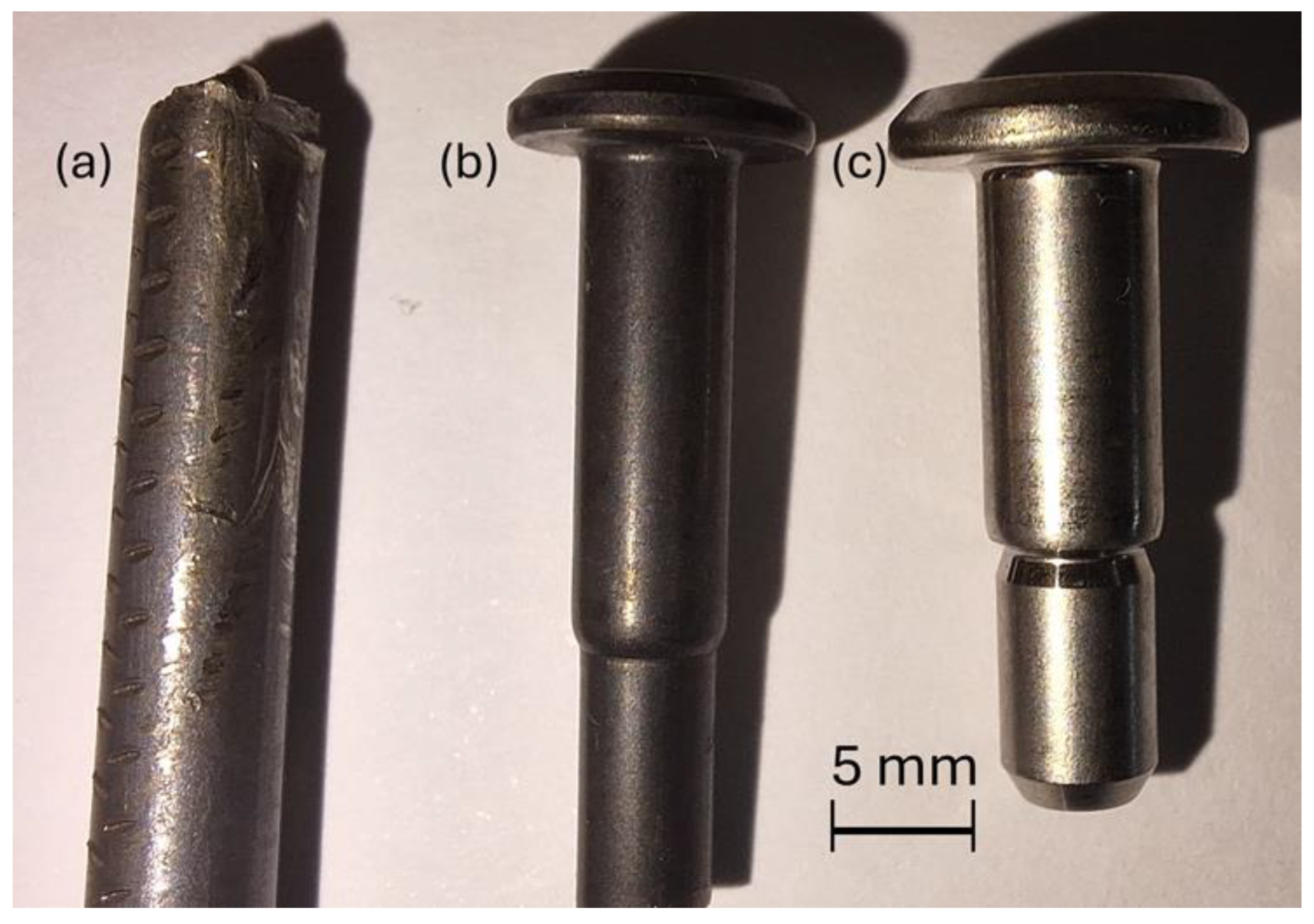
Sections of the as-supplied coiled bar stock or forged fasteners, of several different diameters of Ti-6Al-4V, from different titanium stockists, which had been issued to an aerospace fastener manufacturer, were analysed at the University of Birmingham (see
Figure 1). The bar stock was coated with a proprietary solid-state lubricant, which has a dark colouration (
Figure 1a,b) and partially rubs off when handled. Clearly, the colouration of Ti-6Al-4V is a bright metallic finish (
Figure 1c). The primary analysis performed was to determine the chemical composition of the lubricant layer coating the outside of the coiled bar stock and the thickness and uniformity of the coating.
Subsequently, the efficacy of the molten salt bath removal process was explored to determine the cleanliness of the Ti-6Al-4V bar stock after molten salt trials that varied (i) the time that a sample, within a basket of material for cleaning, spent in the salt bath and (ii) the number of dips into and out of the molten salt bath. The hypothesis that was trying to be tested with the dipping activity was to introduce some stirring or agitation into the molten salt via dipping of the basket to determine if this allowed the molten salt to become more active if not stagnant and to attempt to shake loose any aerospace fasteners that may have become stuck to one another due to van der Waals attractive forces or simply due to surface tension effects of the molten salt liquid. These trials were conducted as molten salt bath cleaning stages can cause a bottleneck in the multi-stage manufacturing of aerospace fasteners, from raw bar stock to final product. As such, any way to speed up the salt bath cleaning process would be industrially beneficial.
Ti-6Al-4V is reported in the literature to have a relatively high microhardness measurement of 320–340 Hv [
25], which can be influenced by post-processing heat treatment operations [
26,
27]. For enabling the titanium alloy to be workable and easier to process, lower hardness values are preferential, whereas to provide higher strength, this usually requires hardness to raise also. As such, there is a continued trade-off between formability for component manufacture and strength and hardness for durability during service. However, given that the titanium alloy fastener substrate is significantly harder than the solid-state lubricant applied, coupled with the inert nature of titanium, methods to remove a layer of lubricant can be both mechanically and chemically quite abrasive.
Trial fasteners that were analysed to compare the effects of time in the salt bath and the effects of dipping are given in
Table 1. An industrial production line salt bath system was utilised, with wire mesh baskets, each containing roughly 10 kg of Ti-6Al-4V-formed fasteners, placed within the salt bath. The salt bath contained a solution of diluted nitric acid with a proprietary, commercially available, so-called low-temperature salt known to promote lubricant layer deflocculation. Hold times within the salt bath used were controlled by manual operation and, as such, are ±5 s. A result of the standard visual inspection for cleanliness by the salt bath operator is also included. All other process parameters of the salt bath, namely the salt used, the operating temperature (350–360 °C), the size of baskets to hold samples in the salt bath, and the volume of material being cleaned in each trial, were held constant. The values used in this parametric study were selected using Taguchi design of experiment (DOE) approaches to explore the design space around the existing industrially implemented strategy whilst allowing for possible processing time reduction to support industrial speed-up.
Scanning electron microscopy (SEM) was used to analyse a lubricated fastener prior to any cleaning process. The bar stock was analysed at cross-sections and outer surfaces. A Hitachi Corp. (Tokyo, Japan) TM4000+ tabletop SEM using the secondary electron imaging was used, primarily for its energy dispersive X-ray spectroscopy (EDS) capability, to determine the chemical composition of the lubricant. The accelerating voltages were 10 kV and 15 kV. The EDS was then analysed using the built-in AZtec system by Oxford Instruments (Abingdon, UK).
Raman spectroscopy was employed to identify bonds present within the samples, to identify compounds that make up the lubricant, and to further establish methods to quantify the cleanliness of samples. A Renishaw plc, (Gloucestershire, UK) Raman spectrometer, equipped with a Renishaw CCD sensor, an Olympus LM-Plan-FL N 50X lens, a 488 nm laser configured to an output of 30 mW, and a grating of 2400 L/mm, from Olympus Corp. (Tokyo, Japan). The parameters for each analysis were the laser at 100% power, a 20 s exposure time, and a spectrum range of 200 to 2800 cm−1.
Surface roughness measurement was performed using a digital optical microscope, a Keyence Corp. (Osaka, Japan) VHX-X1 series microscope. Samples were placed vertically and levelled on the stage of the 4K Ultra-High accuracy microscope, with a separate ring light source, adhering to ISO standards [
28], using transmitted illumination, a shutter speed of 26 s, a Gaussian filter with an S-L surface, using end effect correction and a scale-limited surface, with weak anti-vibration. The samples were focused on magnification ranges (from ×80 to ×400) depending on the thickness of the fastener. Autofocus and increased resolution functions produced high-quality imaging of the centre of the fastener.
A benchtop PROTO Manufacturing Inc. (Taylor, MI, USA) X-ray diffractometer (XRD) machine was used, according to relevant ISO standards [
29], with an inclined X-ray tube set-up with a copper anode with a wavelength of 1.54 Angstrom, to collect experimental results. The equipment is maintained using standard reference material 660b, LaB6 [
30]. The sectioned as-received bar stock and forged fastener were mounted into a large sample holder and measured at intensity values over a diffraction range of 30° < 2θ < 80° with a 1 s dwell time per diffraction degree. The diffraction data were then plotted and baselined.
3. Results
3.1. Identifying the Lubricant
Analysed digital microscopy and SEM imaging have revealed a number of trends in the lubricant coating (see
Figure 2). The thickness of the coating is typically 200 µm thick; however, it can vary, in particular at regions where the out-of-round nature of the cross-section of the bar stock is at its greatest, by up to 40–50 µm. The lubricant surface is relatively smooth, although small protrusions of several microns are evident. Further analysis of the SEM imaging allowed for EDS to measure the compositional data of the lubricant. The compositional elements identified and their weight percentage are shown in
Table 2. Much of the weight percentage found was from carbon (31.73 wt.%), oxygen (30.60 wt.%), and titanium (20.45 wt.%). It is likely that the titanium was measured from the substrate below the lubricant, as was the measurement of aluminium and vanadium. Other elements identified that likely are within the lubricant include sodium, silicon, fluorine, molybdenum, sulphur, potassium, and calcium.
The sodium and silicon detected are likely from the presence of sodium silicate binder, Na2xSiyO2y+x, within the lubricating coating. The molybdenum and the sulphur are likely indicative of the presence of molybdenum disulphide within the lubricant. A trace fluorine component was identified, and research suggested it could be attributed to a triazine component within the lubricant. It is possible that the potassium and calcium that were detected via EDS are anomalies from background contamination within the SEM chamber and are likely not present in the lubricant. They were considerably the lowest weight percentage elements detected. It should be noted that EDS methods do struggle to accurately predict the presence of the lightest elements, which would explain the lack of hydrogen detected. Further, light element detection via EDS is problematic given that any atmospheric contamination will contain carbon and oxygen.
EDS analysis helped identify the presence of fluorine in the lubricant, with the literature [
31] suggesting this was from a triazine compound. However, due to proprietary information being unavailable on triazine chemistry, it was difficult to identify the specific chemicals included within the lubricant. One chemical available for experimental testing [
32], Tris(trifluoromethyl), was analysed using Raman spectroscopy, and a similar XRD peak trace was noted (see
Figure 3), suggesting this is a likely candidate for the source of fluorine. The triazine compound promotes slip mechanisms to prevent wear during the forging process.
3.2. Analysing Salt Bath Efficacy
The X-ray diffraction (XRD) data were analysed for the pre-salt-bath-cleansed samples, as well as the various trials of salt bath cleaned samples. The arising XRD peak traces are given in
Figure 4. Note that the characteristic peaks corresponding to the metallographic elements within the Ti-6Al-4V base substrate are indicated with a star (above the top XRD trace). Whilst peaks corresponding to the sodium silicate binder in the lubricant, noted previously, are indicated by a yellow square, and a peak corresponding to molybdenum disulphide within the lubricant is indicated with a green triangle.
There is evidence of peak-shifting, notably in the presented XRD trace for trial 4. A number of factors can influence peak-shifting, namely the crystal lattice expansion or contraction or changes to the crystallite size. Thermal expansion effects can be eliminated as all experiments were conducted at room temperature. Any stress relief during the molten salt bath process may have had some impact upon peak-shifting, but due to the relatively low temperature of 350 °C for titanium alloy stress relieving, this is again unlikely. The physical size of the crystallite should not particularly vary from sample to sample. Doping or mass transfer may also explain peak-shifting. Whilst it is not anticipated that trial 4 would have experienced any mass transfer between elements present in the lubricant and elements within the alloy, thus this again appears unlikely. It is therefore possible that experimental error—a sample height misalignment in the XRD chamber—may unfortunately be the cause for some slight peak-shifting.
The samples from the different salt bath trials were also analysed by SEM-EDS methods.
Figure 5 illustrates the SEM images taken from the trials incrementally reducing the total time spent in the salt bath. Note that some polishing process artefact scratches are present, as the SEM image is of the surface of the component. Any lubricant still present during polishing will therefore enhance the appearance of scratches, as it gets trapped between the polishing wheel and the surface of the Ti alloy.
The arising EDS chemical composition of the cleaned surface of the Ti-6Al-4V fasteners is given in
Table 3. Similarly,
Figure 6 illustrates the SEM images taken from the set of trials incrementally increasing the number of “dipping” operations of the basket containing fasteners for cleaning, whilst keeping the overall time spent in the molten salt bath constant. Again,
Table 3 highlights the measured chemical composition of the cleaned Ti-6Al-4V fasteners, post-salt bath operations. The lubricated fasteners were therefore not tested, as they have had no cleaning operation performed.
If the Ti, V, and Al elements are ignored as simply a measurement from the clean substrate below, and only the potential contaminant elements from the remnant lubricant are considered, then their concentrations can be represented in the bar chart given in
Figure 7. Fe is likely also measured from the Ti-6Al-4V substrate, as it is a trace element contained within the allowed composition for Ti-6Al-4V, up to a wt.% of 0.25 [
33], which matches the weight percentages detected by EDS. All the trials were reasonably effective at removing molybdenum from the fasteners. However, there was a degree of variability.
Trials 3, 4, 5, and 6 showed no trace of any molybdenum content, but trials 1, 2, 7, and 8 did include small amounts of molybdenum. This is slightly confusing, given that trials 1 and 2 featured the longest hold times within the molten salt bath, whilst trials 7 and 8 featured the greatest number of “dips”, thus should have outperformed the other trials. A more rational trend was observed for the removal of sulphur content of the lubricant. Trials 4, 5, and 7 had low levels of sulphur (0.12%, 0.13%, and 0.06%, respectively). These featured the trials with just two dips and the lowest hold times in the salt bath (4,5). Whereas the fasteners from trials 1, 2, 3, 6, and 8 showed no sulphur present in the EDS spectra. Thus, the bigger hold time, or increasing the number of “dips”, optimised sulphur removal. The results for sodium content were unusual in that all the trials showed no sodium content at all, except for trial 8. Trial 8 had a sodium weight percentage of 0.7%. This was a reduction from the weight percentage of 4.35% in the fasteners, which had yet to be cleaned. However, 0.7% is noticeably high considering all the other samples had a Na weight % of 0. As before, the Ca detected in trial 7 is believed to be an erroneous result caused by atmospheric contamination.
However, by considering trial 1 as the baseline time typically spent in the molten salt bath, with an industrially demonstrated clean surface, then a 10% reduction in this time, trial 2 certainly matches it for cleanliness. Only with further reduction in time spent in the bath (trials 3, 4, and 5) does the presence of elements from the lubricant become apparent. Salt bath engineers can largely remove these trace levels of lubricant by increasing the number of “dips” into and out of the salt bath (trials 6–8), albeit with the Na uncertainty observed in trial 8, and some remnant Mo being detected.
It is prudent to consider the optimal cleaned sample from the salt bath process. Trials 0 and 1 represent the current default industrial methodology for salt bath cleaning. It becomes evident from EDS results that adding a short period to re-dip the sample in the salt bath (trial 1) will somewhat improve the cleaning through agitation to disturb any pins in contact with one another and prevent the molten salt solution from interacting with the surface. A reduction in the hold time in the salt bath by 10% (trial 2) is equally as clean as trial 1. As time in the salt bath continues to reduce to a 40% reduction, whilst 2 dips are implemented, the EDS-measured cleanliness does decline slightly. However, by increasing the number of dipping operations, even the 40% reduction in hold time within the salt bath can still produce a sample as clean as the current industrial process (trial 8). As such, there seem to be two potential ways to speed up the molten salt leaning process. Either a small 10% reduction in hold time appears to give similar cleanliness as the default methods, or a significant reduction in hold time by 40%, but with increased dipping processes to increase agitation.
3.3. Surface Roughness Measurements
Further, it becomes of interest to industry to establish a method to determine the cleanliness and efficacy of a salt bath cleaning operation without very expensive lab equipment such as an SEM equipped with EDS detectors, which can have high maintenance costs as well as high initial purchase costs. As such, a digital Keyence VHX-X1 series microscope (Keyence Corp. Osaka, Japan) with a surface roughness measurement setting was implemented to achieve Sa roughness measurements for the different uncleaned and salt-bath-cleaned samples tested. Sa measurement is the areal average roughness measurement, as opposed to Ra, which is simply from a linear profile. Whilst the digital optical microscope still represents a sizeable outlay (albeit much lower than SEM), any Sa measurement equipment, such as a stylus, or even a simpler Ra measurement system—to the relevant levels of accuracy—could be used to achieve similar roughness measurements. Measured Sa values from the tested samples illustrate an interesting trend (see
Figure 8). The samples evidenced as having lower traces of lubricant elements—the cleaner samples, such as trial 1 and trial 2, display significantly higher surface areal roughness Sa measurements than those suspected of still containing trace amounts of lubricant, such as trials 4 and 5. Note also that the control measurement of the pre-salt bath samples, the as-received lubricated wire, and the lubricated forged fastener had even lower surface roughness still.
4. Discussion
Whilst the SEM-EDS chemical composition analysis has determined the measured surface cleanliness, it is worth noting that all of the trials passed a visual inspection for cleanliness. This is the typical cleanliness check of forged fasteners, at the post-salt-bath-cleaning stage, in an industrial manufacturing process route. This could suggest that a complete removal of all trace elements of the lubricant is an overkill requirement if fasteners of this level of cleanliness pass through subsequent stages of the manufacturing operation, including solution heat treatment, without adverse impacts upon microstructure or properties. This would suggest that a “clean enough” level had been reached. Given that the formation of α-case is of particular concern, and a high oxygen content is the likely initiator for α-case, certainly trials 3–5 would suggest that O was at a concerning level. As such, again it must be stressed that EDS measurements are potentially prone to error for lighter elements such as oxygen, and this high value measured for trials 3–5 may simply be an example of background atmospheric contamination such as dust sitting upon the surface of the sample, despite rigorous preparation and cleaning. Once the sample is placed inside the SEM vacuum chamber, contaminants present are unable to be removed.
The trend observed in the roughness measurements—whereby higher areal roughness Sa values corresponded to the samples deemed to be “cleaner”—can be rationalised if we graphically consider what the presence of a solid lubricant coating is achieving (see
Figure 9). The Ti-6Al-4V bar stock is likely to possess machining marks from the manufacturing operations for forming a narrow diameter bar of typically 4–7 mm. This is potentially formed through drawing operations, and drawing operation tooling can leave a less desirable surface roughness on the formed bar stock. However, once the bar stock is coated in the solid lubricant, likely a simple physical vapour deposition process, the lubricant layer will naturally fill in the crevices within the surface, forming a much smoother surface finish across the lubricant layer.
Once again, the digital microscope was employed to study a clean (trial 2) fastener and a fastener prior to any salt bath cleaning operation being performed to measure surface roughness through profilometry. The digital microscopy images showing the surface of these two fasteners are presented in
Figure 10. The machining grooves and marks, likely present from earlier stages of the coiled bar stock manufacturing route, such as drawing to narrow diameter, are evident in the exposed Ti-6Al-4V alloy surface of the cleaned fastener. However, to more rigorously confirm the hypothesis, surface profilometry experiments were performed.
An example of the generated 2D contour map produced by the profilometry software within the digital microscope is presented in
Figure 11. The full linear profile for a randomly selected plane of measurement in each of the lubricated and cleaned fasteners is presented in
Figure 12. It is therefore observed through experimental methods that the surface roughness for the cleaned Ti-6Al-4V fastener is more than double that of the lubricated, uncleaned fastener, with the largest adjacent peak to trough height delta for the lubricated, coated Ti-6Al-4V fastener measured to be 1.48 μm, whilst the largest adjacent peak to trough height delta for the cleaned Ti-6Al-4V fastener with the metallic surface exposed measured at 3.01 μm. As such, experimental data suggests that by taking relatively simple linear or areal surface roughness measurements, the operator can achieve a qualitative understanding regarding the relative cleanliness of different samples.
Recalling that the Ra value is the arithmetic mean of profile height deviations, calculated using Equation (4), whereby
lr is the distance over which the measurement is taken and
z(
x) is the height as a function of position, the following is obtained:
Thus, the maximum adjacent peak-to-trough measure is the worst instance of roughness observed in the measured length, whilst Ra is a mean value for the surface. The larger adjacent peak-to-trough measurement for the cleaned Ti-6Al-4V sample compared to the lubricated would suggest that the solid-state lubricant layer was gathering within the troughs to reduce this peak-to-trough measurement. Whilst the manufacturing process at the titanium manufacturers is proprietary information [
34], it is presumed that they are coating the coiled bar during the coiling process using a dipping coating method, which is far more cost-effective than any deposition coating methods such as PVD or CVD methods. A dipping process would naturally lend itself to the gathering of lubricant in thicker sections within troughs at the surface.
Giltrow [
35] investigated the lubrication of titanium through applied coatings, whilst Mishra [
36] investigated the friction and wear of bare Ti alloys. Both used pin-on-disc methods to understand friction coefficients, and they observed that breakage of surface layers within wear tracks, such as those noted in the bare Ti-6Al-4V surface (
Figure 10b), causes instabilities in the coefficient of friction. Bansal et al. [
37] researched surface engineering of the Ti-6Al-4V alloy for improvement in durability and lubrication effects of bar stock and, in particular, the deterioration of the coefficient of friction as the coating layer or top surface is subjected to severe wear. Wear tracks were again observed experimentally in the Bansal work [
37], which do appear similar to those presented in the cleaned fastener (see
Figure 10b), which again supports the hypothesis that a protective lubricant layer prevents the accumulation of wear damage during the fastener forging process. However, pre-existing wear damage caused by the coiled bar stock manufacturing history is likely still present below the lubricant coating layer, and due to the significantly higher hardness of the titanium substrate than the lubricant layer, it can be measured to illustrate an effective measurement of cleanliness.

 ,
, 


