Abstract
To calculate the carrying capacity of spherical hydrostatic bearings, a numerical calculation model was presented. The influence law of dynamic pressure effect on the carrying characteristics of liquid hydrostatic spherical bearings is revealed. Under general working conditions, the dynamic pressure effect caused by the radial eccentricity of the bearing has little influence on the bearing load characteristics parameters; when the minimum width of the gap between the sealing edge is very small and the bearing rotational speed is high, the dynamic pressure effect is more obvious.
1. Introduction
Bearings, as the pivotal components of rotating machinery, necessitate a profound understanding of their performance to accurately predict and ensure the functionality of the entire system. In an era that pursues high-speed, high-power output, and stable operation, the precise prediction and control of bearing behavior become paramount. Statistics reveal that over 40% of mechanical failures can be traced back to bearing issues, underscoring the urgency of research aimed at optimizing bearing performance [1,2,3]. To address this challenge, exhaustive and intensive research and analysis have emerged as crucial avenues for enhancing bearing performance and reducing failure rates. Hydrostatic bearings, distinguished by their low operational friction, minimal viscous dissipation, exceptional load-bearing capacity, and high stiffness, occupy an indispensable position in the realms of heavy-duty and high-speed equipment, encompassing machine tools, precision measurement devices, hydraulic piston pumps, motor systems, telescope structures, gyroscope gimbals, dynamometers, radar tracking systems, and marine propulsion units [4,5,6,7].
Notably, spherical bearings exhibit significant advantages over other configurations due to their unique self-aligning capability and the superiority of withstanding both radial and thrust loads simultaneously. This characteristic ensures that spherical bearings maintain stable operational states even in the presence of angular misalignment, remaining unaffected. Consequently, scholars such as Mayer [8] and Elescandarany [9] have adopted a novel approach to theoretically analyze the behavior of this type of bearing and grasp its properties. Unusually, the bearing vibration was studied through fluid dynamics rather than mechanical means, revealing the influence of eccentricity, inertia, restrictor type, valve seat configuration, and supply pressure on performance. New and unique formulas were derived to predict frequency, stiffness, and damping, elucidating how these parameters generate the self-aligning characteristics of the bearing. To effectively reduce power loss and improve stiffness, Kazama [10] designed assembled and clearance thrust spherical bearings using capillary tubes and orifice limiters. Various factors such as surface roughness, centripetal inertia, viscosity, and valve seat configuration of bearings have an impact on the bearing load [11,12,13,14,15]. Elescandarany [16,17,18] introduced innovative techniques for designing fitted spherical bearings, both with and without restrictors and, thus, expanding design possibilities. Rajashekar [19] explored the lubrication characteristics of squeeze films, focusing on the influence of surface roughness and applied pressure. The study used a revised version of the Reynolds equation that included surface roughness and couple stress to examine their effects on bearing lubrication and load capacity. Results showed that higher couple stress led to increased load capacity. In parallel, the effects of velocity slip and viscosity on the lubrication of the squeeze film in spherical bearings were studied by Raghavendra et al. [20]. The genetic algorithms to fine tune the spherical radius and support angle [21] and to improve the performance of spherical bearings by adjusting parameters such as bearing angle, spherical radius, and oil supply vortex radius [22] has been reported in the literature. Luo [23,24] introduced methods to evaluate the static load rating of spherical plain bearings and conducted extensive life tests on new joint bearings with specialized equipment. Spherical bearings have notable applications in ship engineering [23,24,25,26,27,28,29,30,31,32], particularly self-aligning ball bearings used as axial load bearings in hydrofoil ship cylinder flanges, which endured dynamic load tests and achieved a designed carrying capacity of 500 kN. Lastly, Wang, Qian, Li, and colleagues [33,34,35] employed spherical hydrostatic bearings for supporting large marine propellers during static balance tests. Their thorough analysis of bearing capacity, leakage, and pressure distribution emphasized the precision, stability, and user-friendliness of this method for propellers’ static balance testing.
2. Calculation Method for Dynamic Pressure in Spherical Bearings
When two inclined surfaces move relative to each other and the gap between them is filled with fluid, the fluid is dragged into the gradually converging gap due to its viscosity. This results in a localized increase in pressure within the converging gap, a phenomenon known as the dynamic pressure effect. The pressure generated by this effect is referred to as dynamic pressure. Several conditions are necessary for the dynamic pressure effect to occur: there must be an appropriately sized wedge-shaped gap between the moving surfaces, the gap must be filled with a viscous fluid, and the surfaces must have a sufficient relative motion speed.
When a high-speed rotating hydrostatic spherical bearing experiences horizontal eccentricity, all conditions for the dynamic pressure effect are met. Consequently, dynamic pressure is generated within the sealing edge gaps. This dynamic pressure effect disrupts the pressure distribution along the sealing edges, creating unbalanced torques and impacting the stable operation of the spherical bearing.
The spherical hydrostatic bearing comprises a bearing housing and a bearing body, as illustrated in Figure 1.
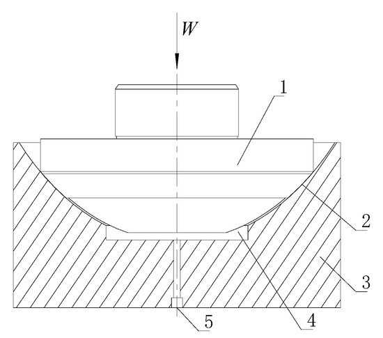
Figure 1.
The structure of spherical hydrostatic bearing. 1—bearing body; 2—oil spill gap; 3—bearing housing; 4—high-pressure oil cavity; 5—oil supply hole. Adapted from [35].
The oil film can be depicted as a narrow gap between surfaces of spherical bearings. A cutting plane, considered along the axis, is defined with the sphere’s radius labeled as R. The high-pressure oil chamber angle is denoted as 2θ1, while the oil seal angle on one side is marked as θ2. The bearing is suspended within the high-pressure hydraulic oil. For the sake of simplicity, the analysis focuses exclusively on the vertical eccentricity of the bearing, neglecting horizontal eccentricity. Figure 2 depicts the vertical distance associated with spherical eccentricity and the subsequent oil seal edge, with the values R = 350 mm, θ1 = 31°, θ2 = 8°.
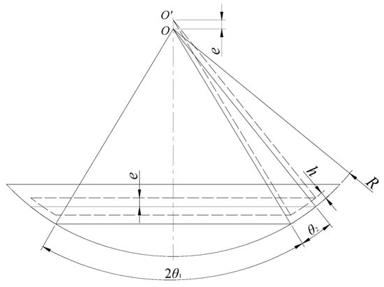
Figure 2.
Schematic of the spherical bearing oil sealing edge. Adapted from [35].
A spherical coordinate system is established in the spherical bearing oil seal model, as shown in Figure 3.
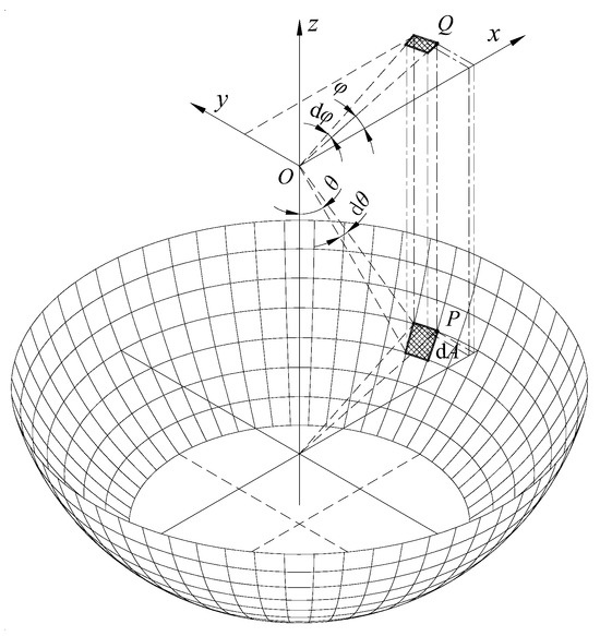
Figure 3.
Discrete model of spherical bearing and parameter definition. Adapted from [35].
The pressure resulting from the dynamic pressure effect can be determined by solving the Reynolds equation. Under isothermal conditions, the Reynolds equation in spherical coordinates can be expressed as follows:
Assuming the hydraulic oil is an incompressible fluid, for incompressible steady flow, Equation (1) can be simplified as follows:
Equations (1) and (2) can be further decomposed into:
When the bearing body becomes eccentric, let the radial eccentricity be denoted as e1 and the axial (vertical) eccentricity be denoted as e2. The gap width at the sealing edge can then be expressed as:
The gap, denoted as h, is determined by the angle, θ, and the spherical radius, R; radial eccentricity, e1 = e, is shown in Figure 2, and axial (vertical) eccentricity, e2, is illustrated in Figure 4.
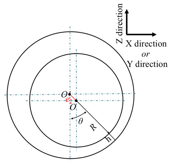
Figure 4.
Slit schematic diagram of spherical eccentricity.
The above Reynolds equation is a partial differential equation involving two variables: the gap width and the pressure. Since the gap width is already expressed in Equation (4), solving the equation essentially means solving for the pressure. Researchers have proposed various effective methods for solving the Reynolds equation, such as the finite difference method, the finite volume method, and the finite element method. Among these, the finite difference method is widely acknowledged for its early application, simplicity, effectiveness, and the flexibility in controlling computational errors.
The basic concept of the finite difference method involves dividing the solution domain into a finite number of computational nodes, where the unknown quantities at each node are expressed in terms of the values at neighboring nodes. Typically, this entails replacing the derivatives of the unknown quantities with difference approximations derived from adjacent nodes, thereby converting the differential equation into a system of linear algebraic equations at the nodes. Through iterative computations, the values of the unknown quantities at all nodes are determined. In the finite difference method, boundary conditions are set as known values or specified relationships at certain boundary nodes.
The pressure value at node (i,j), denoted as p(i,j), can be expressed as [36,37]:
In Equation (5), the coefficients Ai,j, Bi,j, Ci,j, Di,j, and Ei,j, can be derived from Equations (3) and (4).
To solve the spherical bearing oil-sealing edge model using numerical calculation methods, the physical model needs to be discretized into a finite number of elements first. The circumferential angle of the oil-sealing edge, ranging from 0 to 2π, is discretized into m elements, with a circumferential step size of dφ = 2π/m, and the node numbers ranging from 1 to m. The axial angle, from θ1 to (θ1 + θ2), is discretized into n elements, with an axial step size of dθ = θ2/n, and the node numbers ranging from 1 to n + 1. Additionally, the thickness of the oil-sealing edge gap, h, is discretized into k elements, with a thickness step size of dh = h/k, and the node numbers ranging from 1 to k + 1, as illustrated in Figure 5.
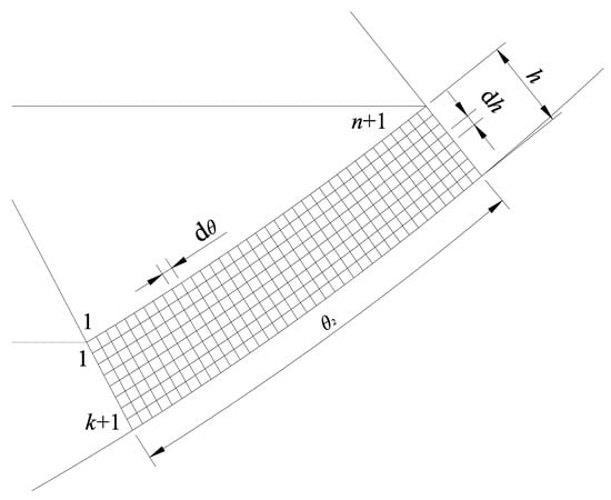
Figure 5.
Discrete model of the oil-sealing edge gap.
There are various methods to solve the above system of algebraic equations. Among them, the iterative method stands out for its simplicity, stability, and relatively low computational cost. The iterative method involves assigning an initial estimated value to the unknown quantity at each node and then using Equation (5) to calculate an updated pi,j value. This updated value replaces the original estimate, and the process is repeated for all nodes. Through multiple iterations, increasingly accurate p values are obtained, eventually achieving the desired precision.
After completing the calculations for all nodes in each iteration, it is necessary to determine whether the results have achieved the required accuracy. The convergence criterion used in this paper can be expressed as:
In the equation, [Δ] represents the allowable convergence error, set at 0.001.
After calculating the dynamic pressure in the sealing edge gap, the forces exerted by this dynamic pressure on the spherical bearing body can be determined using numerical integration methods.
From the derivation of the Reynolds equation, it is assumed that there is no axial flow. In hydrostatic spherical bearings, axial flow is primarily caused by hydrostatic pressure differences. On the other hand, dynamic pressure values are generally small, and the influence of hydrostatic pressure on dynamic pressure calculations is significant. Therefore, when calculating the dynamic pressure effect, the hydrostatic pressure difference should be set to zero. This precludes solving for both circumferential and axial flows simultaneously in the dynamic pressure effect calculation.
3. Results and Discussion
In this paper, using the hydrostatic spherical bearing model described in [35] as an example, we examine the impact of dynamic pressure effects on the characteristic parameters of hydrostatic spherical bearings. Based on the analysis of the dynamic pressure calculation method, the following assumptions are made for the computational model:
To avoid the influence of surface elastic deformation on the results, the surface elastic deformation of bearing components is not considered in the calculations.
As seen from Equation (3), both the viscosity of the hydraulic oil and the bearing rotational speed are important factors affecting the dynamic pressure effect, appearing as coefficients on the right-hand side of the equation. Since the viscosity’s variation range is small and relatively stable, we assume a constant hydraulic oil viscosity and primarily discuss the dynamic pressure effect relative to changes in the bearing rotational speed.
For the calculation of the dynamic pressure effect, we assume that the pressure in the high-pressure oil chamber is zero, thereby eliminating any axial flow driven by hydrostatic pressure differences.
Given a radial eccentricity, e1 = 0.25 mm, and an axial eccentricity, e2 = 0.25 mm, for the bearing body, along with a rotational speed of 100 r/min, we input these values along with other parameters listed in Tables 1 and 2 from reference [35] into the computational program. The solutions yielded the distribution of the oil film gap width and the dynamic pressure after accounting for the bearing body’s eccentricity. The results are illustrated in Figure 6 and Figure 7.
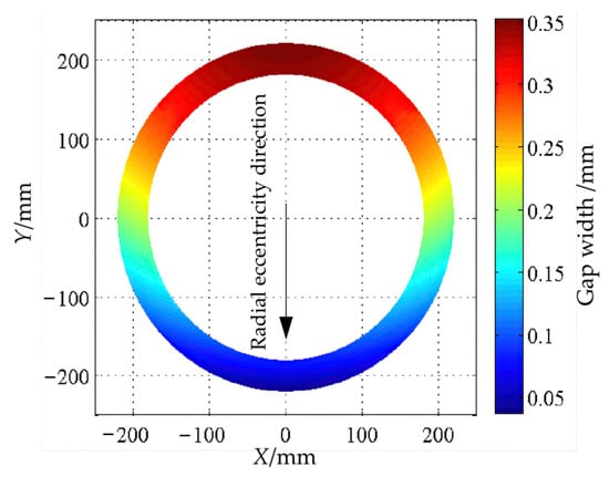
Figure 6.
Top view of the width distribution of the sealing edge gap.
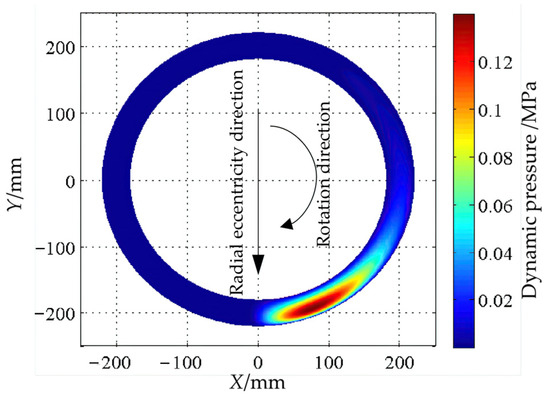
Figure 7.
Top view of dynamic pressure distribution at the sealing edge.
Based on the above computational results, it is evident that after the bearing body experiences eccentricity, the gap width at the oil-sealing edge is significantly reduced in the direction of radial eccentricity. Along the same axial cross-section, the gap width at the oil-sealing edge’s outlet is smaller compared to the inlet. The minimum gap width occurs at the oil-sealing edge’s outlet in the direction of radial eccentricity.
From the pressure distribution diagram, it can be observed that most of the oil film gap within the oil-sealing edge maintains a relatively low pressure. On the side where the gap width decreases along the direction of the bearing body’s rotation, local pressure increases are observed near the region of the minimum gap width. This high-pressure zone, which tends to be near the oil-sealing edge’s outlet, reaches a maximum pressure of approximately 0.14 MPa. The elevated pressure in this area is attributed to the dynamic pressure effect. Analyzing the dynamic pressure distribution for different radial eccentricities reveals that as the radial eccentricity increases, the high-pressure zone becomes progressively smaller, the pressure gradient increases, and the maximum dynamic pressure rises accordingly.
The maximum dynamic pressure reflects the intensity of the dynamic pressure effect and, thus, serves as a measure of its strength. The minimum gap width at the oil-sealing edge is a crucial factor in determining the dynamic pressure effect. When the bearing body undergoes axial and radial eccentricity, it essentially alters the dynamic pressure effect by changing this minimum gap width.
The transversal distribution of the pressure of the spherical hydrostatic bearings is shown in Figure 8.
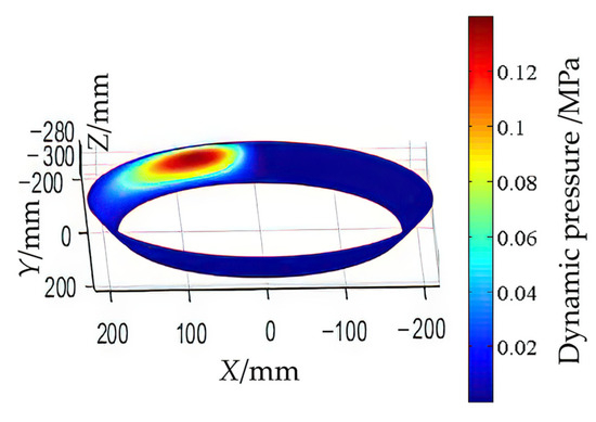
Figure 8.
The transversal distribution of the pressure of the spherical hydrostatic bearings.
The primary force in a spherical hydrostatic bearing, namely the axial carrying capacity, emanates from the Z-direction. The transversal distribution of pressure in the X and Y directions plays a secondary role in determining the bearing’s carrying capacity. Therefore, only the axial carrying capacity is researched in this paper.
With a constant axial eccentricity, e2 = 0.25 mm, we incrementally increase the radial eccentricity, which results in a corresponding reduction in the minimum gap width at the oil-sealing edge. We then investigate how the maximum dynamic pressure varies with the minimum gap width at different rotational speeds. The resulting variation curves are presented in Figure 9.
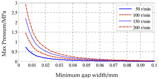
Figure 9.
The variation of maximum pressure with the minimum width of the sealing edge gap at different speeds.
The curves indicate that the minimum gap width at the oil-sealing edge and the maximum dynamic pressure exhibit an approximately inverse relationship. At a given rotational speed, as the minimum gap width decreases, the maximum dynamic pressure increases, with the rate of change also accelerating. When comparing the maximum dynamic pressure at different rotational speeds relative to the minimum gap width, it is evident that, for the same gap width, higher bearing rotational speeds result in higher maximum dynamic pressures. As the gap width narrows, the influence of rotational speed on the maximum dynamic pressure becomes more pronounced. When the gap width is very small, the maximum dynamic pressure is significantly high and highly sensitive to changes in rotational speed. At higher rotational speeds, the maximum dynamic pressure can become substantial, which may adversely affect the stable operation of the bearing.
For hydrostatic spherical bearings, the dynamic pressure resulting from the dynamic pressure effect acts on the bearing surface and contributes to an increased load-carrying capacity to some extent. By integrating the computed dynamic pressures, we can determine the axial load-carrying capacity generated by the dynamic pressure effect. The curves illustrating how the axial dynamic load-carrying capacity varies with the minimum gap width at the oil-sealing edge under different rotational speeds are shown in Figure 10.
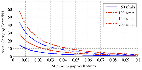
Figure 10.
Variation of axial dynamic pressure bearing capacity with minimum width of sealing edge gap at different speeds.
The variation of the axial dynamic load-carrying capacity due to the dynamic pressure effect follows a similar pattern to that of the maximum dynamic pressure with respect to bearing rotational speed and the minimum gap width at the oil-sealing edge. When the minimum gap width is small, the axial dynamic load-carrying capacity is significantly higher and changes rapidly with the width. This effect is particularly pronounced at higher rotational speeds where the axial dynamic load-carrying capacity is relatively large. However, compared to the static load-carrying capacity that a hydrostatic spherical bearing typically withstands during normal operation, the load-carrying capacity generated by the dynamic pressure effect is relatively minimal and can be considered negligible.
4. Conclusions
The impact of dynamic pressure effects on the load-carrying performance of liquid hydrostatic spherical bearings can be significant. Analyzing the dynamic pressure distribution reveals that local high-pressure areas emerge near the minimum gap on the side where the gap width decreases in the direction of the bearing body’s rotation. These localized high-pressure zones generate unbalanced torque, potentially affecting the stable operation of the bearing.
Furthermore, the high pressure near the minimum gap width can prevent further reduction in the gap, counteracting the external forces causing bearing eccentricity and ultimately stabilizing the bearing body at a certain eccentric position. In terms of the forces generated by the dynamic pressure effect, the axial component acting on the bearing body is relatively small and can be considered negligible.
From the observed trends, it is evident that the smaller the minimum gap width and the higher the rotational speed, the stronger the dynamic pressure effect and the greater its influence. Therefore, it is advisable to minimize large eccentricities in the bearing body to avoid significant dynamic pressure effects.
Author Contributions
Conceptualization, S.Z. and G.L.; methodology, F.Z.; data curation, S.Z. and J.L.; writing—original draft preparation, S.Z. and G.L.; writing—review and editing, S.Z., D.Y., Y.C., G.L., F.Z. and W.S. All authors have read and agreed to the published version of the manuscript.
Funding
This research and APC were funded by the Shandong Province Higher Education Undergraduate Teaching Reform Research Project (No. Z2023085), the “Hundred Outstanding Talents” of Jining University (No. 2023ZYRC56), Science and Technology Innovation Team Foundation of Jining University (23KCTD07), the Key Research and Development Program of Jining of China (2022HHCG014), and the Scientific Research Foundation of Jining University (2022HHKJ02, 2023HHKJ04).
Data Availability Statement
Data are contained within the article.
Conflicts of Interest
Author D.Y. was employed by the company Shandong Xinneng Shipbuilding Co., Ltd. Author F.Z. was employed by the company Jinan Xiangderui Intelligent Technology Co., Ltd. The other authors conducted the research in the absence of any commercial or financial relationships that could be construed as a potential conflict of interest.
References
- Deng, H.; Hu, C.; Wang, Q.; Wang, L.; Wang, C. Friction and wear analysis of the external return spherical bearing pair of axial piston pump/motor. Mech. Ind. 2020, 21, 104. [Google Scholar] [CrossRef]
- Lin, S.C. Friction and Lubrication of sliding bearings. Lubricants 2023, 11, 226. [Google Scholar] [CrossRef]
- Li, J.; Yamada, S.; Kishiki, S.; Yamazaki, S.; Watanabe, A.; Terashima, M. Experimental and numerical study of spherical sliding bearing (SSB)-part 2: Friction models. In Proceedings of the 17th World Conference on Earthquake Engineering, 17WCEE, Sendai, Japan, 28 September–2 October 2021. [Google Scholar]
- Ryan, K.L.; Mojidra, R. Analysis of effect of vertical ground shaking in bridges isolated with spherical sliding bearings. Earthq. Eng. Struct. Dyn. 2023, 52, 5010–5032. [Google Scholar] [CrossRef]
- Deng, H.; Zhu, P.; Hu, C.; He, T. Study on dynamic lubrication characteristics of the external return spherical bearing pair under full working conditions. Machines 2022, 10, 107. [Google Scholar] [CrossRef]
- Tomar, A.K.; Sharma, S.C. Non-Newtonian lubrication of hybrid multi-recess spherical journal bearings with different geometric shapes of recess. Tribol. Int. 2022, 171, 107579. [Google Scholar] [CrossRef]
- Yang, Y.; Zhang, Y.; Ju, J. Study on the mechanical properties of a type of spherical bearing. J. Theor. Appl. Mech. 2021, 59, 539–550. [Google Scholar] [CrossRef]
- Meyer, D. Reynolds equation for spherical bearings. J. Tribol. 2003, 125, 203–206. [Google Scholar] [CrossRef]
- Elescandarany, A.W. Analytical study of the spherical hydrostatic bearing dynamics through a unique technique. Sci. Rep. 2023, 13, 19364. [Google Scholar] [CrossRef]
- Kazama, T. Design of hydrostatic spherical bearings in fluid film lubrication. J. Tribol. 2000, 1228, 66–69. [Google Scholar] [CrossRef]
- Yacout, A.W.; Ismail, A.S.; Kassab, S.Z. The combined effects of the centripetal inertia and the surface roughness on the hydrostatic thrust spherical bearings performance. Tribol. Int. 2007, 40, 522–532. [Google Scholar] [CrossRef]
- Elescandarany, A.W.Y. The effect of the fluid film variable viscosity on the hydrostatic thrust spherical bearing performance in the presence of centripetal inertia and surface roughness. Int. J. Mech. Eng. Appl. 2018, 6, 1–12. [Google Scholar] [CrossRef]
- Yacout, A.W.; Ismail, A.S.; Kassab, S.Z. The surface roughness effect on the hydrostatic thrust spherical bearings performance (part 2 un-recessed clearance type). In Proceedings of the ASME, International Mechanical Engineering Congress and Exposition, IMECE2006-13004, Chicago, IL, USA, 5–10 November 2006. [Google Scholar] [CrossRef]
- Yacout, A.W.; Ismail, A.S.; Kassab, S.Z. The surface roughness effect on the hydrostatic thrust spherical bearings performance (part 3 recessed clearance type of bearings). In Proceedings of the ASME International Mechanical Engineering Congress and Exposition, IMECE 2007-41013, Seattle, WA, USA, 11–15 November 2007. [Google Scholar] [CrossRef]
- Elescandarany, A.W. Externally pressurized thrust spherical bearing performance under variable lubricant viscosity (un-recessed clearance type). Int. J. Mech. Eng. Appl. 2020, 8, 45–64. [Google Scholar] [CrossRef]
- Elescandarany, A.W.Y. Design of the hydrostatic thrust spherical bearing with restrictors (fitted type). Int. J. Mech. Eng. Appl. 2019, 7, 34–45. [Google Scholar] [CrossRef]
- Elescandarany, A.W.Y. Design of self-restriction hydrostatic thrust spherical bearing (fitted type). Int. J. Mech. Eng. Appl. 2019, 7, 111–122. [Google Scholar] [CrossRef]
- Elescandarany, A.W. Kugel ball as an interesting application of designing the hydrosphere. Int. J. Mech. Eng. Appl. 2021, 9, 25–32. [Google Scholar] [CrossRef]
- Rajashekar, M.; Kashinath, B. Effect of surface roughness on MHD couple stress squeeze-film characteristics between a sphere and a porous plane surface. Adv. Tribol. 2012, 2012, 935690. [Google Scholar] [CrossRef]
- Rao, R.R.; Gowthami, K.; Kumar, J.V. Effects of velocity-slip and viscosity variation in squeeze film lubrication of spherical bearings. In Proceedings of the International Conference on Advances in Tribology and Engineering Systems: ICATES, Ahmedabad, India, 15–17 October 2013; Springer: Delhi, India, 2013; pp. 35–47. [Google Scholar] [CrossRef]
- Tao, J.Z.; Yin, G.F.; Wang, F.Y. An optimism method of air static pressure ball bear parameters. China Mech. Eng. 2004, 15, 48–50. [Google Scholar] [CrossRef]
- Guo, X.P.; He, H.T.; Zhao, L. Optimization design of non-liquid friction spherical sliding bearing based on ANSYS. Bearing 2007, 2, 4–5. [Google Scholar] [CrossRef]
- Luo, L.; Wang, X. Finite element analysis of self-Lubricating joint bearing liner wear. In Proceedings of the 2017 International Conference on Computer Technology, Electronics and Communication (ICCTEC), Dalian, China, 19–21 December 2017; pp. 245–249. [Google Scholar] [CrossRef]
- Luo, L.; Wang, X.; Liu, H.; Zhu, L. Number simulation analysis of self-lubricating joint bearing liner wear. Int. J. Interact. Des. Manuf. 2019, 13, 23–34. [Google Scholar] [CrossRef]
- Royston, T.J.; Basdogan, I. Vibration transmission through self-aligning (spherical) rolling element bearings: Theory and experiment. J. Sound Vib. 1998, 215, 997–1014. [Google Scholar] [CrossRef]
- Geng, K.; Lin, S. Effect of angular misalignment on the stiffness of the double-row self-aligning ball bearing. Proc. Inst. Mech. Eng. Part C J. Mech. Eng. Sci. 2020, 234, 946–962. [Google Scholar] [CrossRef]
- Ambrożkiewicz, B.; Syta, A.; Gassner, A.; Georgiadis, A.; Litak, G.; Meier, N. The influence of the radial internal clearance on the dynamic response of self-aligning ball bearings. Mech. Syst. Signal Process. 2022, 171, 108954. [Google Scholar] [CrossRef]
- Zhuo, Y.; Zhou, X.; Yang, C. Dynamic analysis of double-row self-aligning ball bearings due to applied loads, internal clearance, surface waviness and number of balls. J. Sound Vib. 2014, 333, 6170–6189. [Google Scholar] [CrossRef]
- Parmar, V.; Saran, V.H.; Harsha, S.P. Effect of an unbalanced rotor on dynamic characteristics of double-row self-aligning ball bearing. Eur. J. Mech. A/Solids 2020, 82, 104006. [Google Scholar] [CrossRef]
- Parmar, V.; Saran, V.H.; Harsha, S.P. Nonlinear vibration response analysis of a double-row self-aligning ball bearing due to surface imperfections. Proc. Inst. Mech. Eng. Part K J. Multi-Body Dyn. 2020, 234, 514–535. [Google Scholar] [CrossRef]
- Liu, Z.L.; Lu, J.; Zhou, J.N. The research on the design of largescale static pressure spherical bearing used in propeller balancing installation. J. Wuhan Univ. Technol. 2003, 27, 429–432. [Google Scholar]
- Liu, Z.L.; Xiao, H.L.; Zhou, J.N. Design of large-sized static pressure ball bearing. Ship Eng. 1999, 5, 25–27. [Google Scholar]
- Wang, C.T.; Wu, U.J.; Chen, L. Algorithm improvement and experimental research for propeller static balancing detection. Sci. Technol. Eng. 2015, 15, 294–297. [Google Scholar]
- Qian, L.B.; Jiang, Y.H. Design of mechanical prop based on space and tracks movement. Equip. Manuf. Technol. 2012, 3, 8–9. [Google Scholar]
- Zhang, S.; Yang, D.; Li, G.; Cheng, Y.; Chen, G.; Zhang, Z.; Li, J. Carrying capacity of spherical hydrostatic bearings including elastic deformation. Lubricants 2024, 12, 97. [Google Scholar] [CrossRef]
- Huang, W.X.; Li, J.M.; Xiao, Z.Y. Engineering Fluid Mechanics; Chemical Industry Press: Beijing, China, 2009. [Google Scholar]
- Xu, X.L.; Deng, H.S.; Wang, C.L. Theory study of spherical interstitial flow. China Hydraul. Pneum. 2004, 10, 3–5. [Google Scholar]
Disclaimer/Publisher’s Note: The statements, opinions and data contained in all publications are solely those of the individual author(s) and contributor(s) and not of MDPI and/or the editor(s). MDPI and/or the editor(s) disclaim responsibility for any injury to people or property resulting from any ideas, methods, instructions or products referred to in the content. |
© 2024 by the authors. Licensee MDPI, Basel, Switzerland. This article is an open access article distributed under the terms and conditions of the Creative Commons Attribution (CC BY) license (https://creativecommons.org/licenses/by/4.0/).