Abstract
This study has investigated the influence of journal bearing wear on the dynamic behaviour of a flexible rotor with a central disc. Rotors supported on journal bearings are susceptible to self-excited whirling, leading to unstable conditions. Prior knowledge of the stability limit speed is important to avoid the excessive vibration of rotating machines. For the study in this paper, journal bearings were lubricated with powder owing to high-temperature applications where conventional oil lubricants would fail to perform. The governing equations for lubrication were derived using a simplified grain theory based on the theory of dense gases. The rotor shaft was discretized considering Timoshenko beam elements. Modal analysis was conducted to obtain the system’s natural frequencies, mode shapes, damping factors, stability limit speed, and unbalance response. This study has also evaluated the influence of wear depth on the dynamic behaviour of the rotor shaft system and found that bearing wear significantly affects the stiffness and damping characteristics of lubricating film. Consequently, free and forced vibration behaviour is also affected. It has been found that increased wear depth improves stability limit speed but has little influence on the unbalance response.
1. Introduction
Journal bearings exhibit excellent lubrication and load-bearing capabilities, due to which it is commonly used to support heavy rotating equipment such as steam turbines and industrial gas turbines. However, when exposed to high temperatures, conventional lubricating oils may deteriorate and become ineffective. Under such circumstances, powder lubricants can be a viable alternative, as they perform well in high-temperature environments [1,2,3]. Moreover, bearing wear can occur due to extended periods of operation or frequent start/stop cycles, which can influence bearing clearance and ultimately change the dynamic behaviour of rotor-bearing system. The present study explores the influence of bearing wear on the dynamic behaviour of a rotor-bearing system.
Modelling powder flow is complicated for many reasons; thus, several researchers have attempted to develop governing equations using continuum and discrete approaches [4]. In the context of the application of powder flow in bearing lubrication, the simplest yet most powerful theory explaining the general features of grain flow is due to Haff [5], who utilized the theory of dense gases to analyse granular flow, incorporating a microscopic model to relate the parameters present in conservation laws. The performance of a slider bearing was investigated using Haff’s model, and analytical solutions were obtained for an infinitely wide slider [6]. For journal bearings lubricated with powders, a closed-form lubrication equation was developed by Tsai and Jeng [7,8], and their numerical results were validated with the experimental findings of Heshmat and Brewe [9]. Higgs and Tichy [10,11] used a slightly different continuum approach to develop a granular kinetic lubrication model with appropriate rheological constitutive equations for stress in a thin shearing flow of granular particles. A robust numerical code using the finite difference method for simple shearing flows has also been developed. Sawyer and Tichy [12] conducted a study involving continuum and particle analyses, comparing their results with those of prior experiments. Although the load-carrying capacity and shear force predicted by both models were higher than those in the experimental data, the trends and orders of magnitude were similar. Recently, the force chain characteristics of shearing granular media have been studied for parallel sliding friction pairs [13], journal bearings [14], and Taylor–Couette geometry [15] using the discrete element method.
Modal analysis is a powerful method to evaluate the natural frequencies and responses of multi-degree freedom systems. Irretier [16] developed a comprehensive mathematical framework for applying modal analysis to rotating systems. Rotating systems have asymmetrical and speed-dependent system matrices, making their modal characteristics speed-dependent as well. Rotors supported on journal bearings require an evaluation of bearing coefficients, which depend on both speed and bearing geometry. These bearing coefficients are necessary for the correct estimation of the dynamics of the machine. The theoretical evaluation of bearing coefficients is restricted to short bearing approximation (length-to-diameter ratios of less than 0.5) and can be found in refs. [17,18]. For a finite bearing, coefficients can be evaluated numerically using the perturbation technique [19,20]. Negatively cross-coupled stiffness tends to destabilize the whirling of rotors due to a tangential force acting in the direction of the whirl orbit. The magnitude of the tangential force will increase with the spin speed; thus, after a certain speed, the rotor will become unstable. EI-Shafei et al. [21] conducted an experimental study to explore the factors that contribute to the instability in a journal bearing that supports a flexible rotor.
Bearing wear, caused by prolonged operation or repeated start/stop cycles, affects bearing clearance and dynamic coefficients. A model for wear geometry was developed by Dufrane et al. [22] after they measured the wear in the bearing of a steam turbine. The same model was verified by Hashimoto et al. [23], who studied the effects of wear on the performance parameters of laminar as well as turbulent regimes. A thermo-hydrodynamic analysis of worn journal bearings was carried out by Fillon and Bouyer [24], and it was found that up to 20% of wear had little influence on performance parameters but wear of more than 20% reduced the temperature inside the film. Papadopoulos et al. [25] proposed a method for detecting wear in hydrodynamic bearings based on the analysis of measured rotor responses at specific locations. Gertzos et al. [26] introduced a graphical technique to identify the wear depth associated with the measured performance parameters. Chasalevris et al. [27] found that worn bearings have additional frequency components in the continuous wavelet transform (CWT) of measured responses. Recently, Machado et al. [28,29] examined the influence of wear on the response of a rotor-bearing system using a slightly modified wear model introduced by Dufrane et al. [22]. This wear model considered a slight angular shifting of wear towards the right to match practical conditions. In another study, Machado et al. [30] utilized the response spectrum to diagnose wear. Konig et al. [31] presented a new numerical method to predict wear in journal bearings during steady-state operation. This method considers wear on both the macroscopic and asperity contact scales and shows that reduced asperity interaction due to wearing-in leads to higher accuracy of wear prediction. In recent times, machine learning, along with vibration signals, has emerged as a viable method for condition monitoring and wear fault diagnosis. Gecgel et al. [32] proposed a framework using a deep learning algorithm to classify wear faults in hydrodynamic journal bearings using simulated vibration signals, which can be a promising tool for wear fault diagnostics in journal bearings. Mokhtari et al. [33] presented the use of machine learning algorithms applied to Acoustic Emission (AE) signals for monitoring friction and wear of journal bearings in jet engines containing a gearbox. Konig et al. [34] discussed the use of Acoustic Emission (AE) technique and machine learning methods for wear monitoring in sliding bearing systems. The study achieved high accuracy and sensitivity in detecting and classifying wear failure modes, including running-in, inadequate lubrication, and particle-contaminated oil.
Previous studies have focused on conventional oil lubricants. However, this work aims to investigate the dynamics of rotors supported on journal bearings with powder lubricants. The wear depth influences the bearing coefficients, which further influences the dynamics of the complete system. Thus, the influence of wear on the modal characteristics is also examined. The rotor–shaft system is modelled using Timoshenko beam elements, and each node is assigned four degrees of freedom. The equations of motion, which are obtained by assembling system matrices, are utilized to evaluate eigenvalues, modal damping factors, stability limit speed, and unbalance response.
2. Mathematical Model
2.1. Grain Theory
Haff [5] developed a simple grain theory that treats grain flow as a fluid mechanics problem. The laws of mass, momentum, and energy conservation were employed to examine granular flow. Constitutive equations were obtained from a microscopic model of grain–grain collisions, using the kinetic theory of dense gases. With assumptions such as grain particles being cohesionless identical spheres of diameter d with negligible separation s, and considering a fluctuation velocity of grain particles together with the bulk flow velocity V, it can be shown that the relations for the pressure p, viscosity , thermal diffusivity K, and energy lost per unit volume per second I can be written as follows (see ref. [5] for details):
where, and are dimensionless constants. The term is collision rate.
Flow velocities u, v, and w vary gradually from point to point in the flow field. Since viscous forces are due to relative motion between two layers, they will take the same form as in a hydrodynamic system [5]. Continuity, momentum, and pseudo-energy equations for granular flow are written as,
In Equations (3)–(6), represents total derivative.
2.2. Application to Bearing Lubrication
The schematic of a worn journal bearing is shown in Figure 1. Following simplifying assumptions are considered to derive a governing equation similar to the classical Reynolds equation of hydrodynamic lubrication.
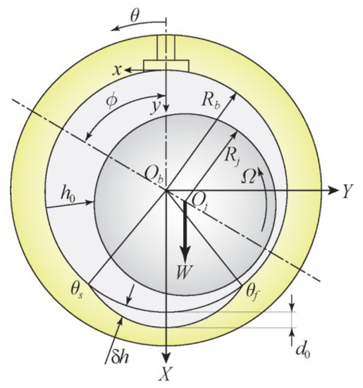
Figure 1.
Schematic of a worn journal bearing.
- Inertia forces and body forces can be neglected in comparison with viscous forces.
- Pressure is considered constant across the film.
- The terms , and their derivatives are negligible in comparison with , and their derivatives.
- The term , and their derivatives are negligible in comparison with .
With these assumptions, Equations (3)–(6) can be reduced to the following:
Treating viscosity in Equations (7) and (8) as the average value across the film [8,35], the modified Reynolds equation is obtained as (see ref. [35] for details) the following:
where , .
Film forces can be obtained through the integration of pressure over the bearing surface as written below.
The resultant film force on the bearing surface is obtained as the following:
Shearing force on the bearing surface is obtained through the following relation:
The coefficient of friction is calculated as the following:
Stiffness and damping coefficients of the powder film are obtained using the finite perturbation technique [19,20]. With very small perturbations of displacements and velocities about the steady state position of the journal centre, bearing forces are obtained. Employing central difference, coefficients of stiffness and damping are written as,
2.3. Modelling of Bearing Wear
Dufrane et al. [22] proposed a mathematical model for bearing wear after careful experimentation which was validated experimentally by Hashimoto et al. [23]. An additional depth in the angular span from to (see Figure 1) is incorporated for the film thickness and is written as,
where, and are the normalized coordinates in the coordinate system, and is the normalized maximum wear depth. The range of angular position of the worn region ( and ) is determined by the solution of the equation,
2.4. Modal Analysis of Rotors
Modal analysis is a powerful method to decouple equations of motion through a coordinate transformation using a modal matrix. The uncoupled equations are solved independent of each other in the modal coordinates and then solutions are combined to obtain the response of the original system. Unlike non-rotating structures, the rotating systems are Non-Self Adjoint (NSA) systems wherein both right and left eigenvectors are required for modal analysis.
The shaft has distributed mass and stiffness due to flexibility. The shaft is modelled using a two-noded Timoshenko beam element having four degrees of freedom at each node. The nodal displacement vector can be written as,
The equations of motion were written for each element and then assembled with boundary conditions to obtain the equations of motion as,
where, , , and
The mass matrix consists of translatory and rotary inertia matrices. The overall damping matrix consists of the gyroscopic matrix , and the bearing damping matrix . The overall stiffness matrix is the sum of the bearing stiffness matrix and the shaft stiffness matrix . denotes the spinning speed. and are the global displacement and force vectors. The state-space form of Equation (20) is written as [36],
where By setting in Equation (21), the equation of motion for free vibration is obtained as,
The solution of Equation (22) results in an eigenvalue problem , where is the eigenvalue and is the corresponding eigenvector. The adjoint eigenvalue problem has same eigenvalues but different eigenvectors because is generally a non-symmetric matrix . Eigenvectors and are known as right and left eigenvectors, respectively. Constructing matrices of eigenvalues , right eigenvectors , and left eigenvectors , as the biorthonormality condition is expressed as,
The solution of the state vector in Equation (21) can be assumed as a linear combination of , where is the modal coordinate. Thus, is written as,
Substituting Equation (24) into Equation (21), and premultiplying throughout by , the following equation is obtained.
Using the biorthonormality condition given in Equations (23) and (25) can be transformed to
where is known as the modal excitation vector. Independent modal equations can be extracted from Equation (26) as,
where . Considering as a harmonic force with frequency , the steady state response is given below:
Substitution of Equation (28) into Equation (24) provides the solution of state vector as,
3. Computational Procedure
The modified Reynold’s Equation (10) is discretized using finite difference method, and the resulting algebraic equations are solved for pressure iteratively with successive over-relaxation. The criterion for convergence of pressure in the lubricating film is chosen as,
where i, j are indices of grid points, and m, n are the total nodes in and z directions, respectively. is the error in pressure between successive iterations, and N is the iteration number. The grid size used in the present study is , which is determined after a grid-independent test.
After computing the pressure field, film forces are obtained through numerical integration of Equations (11) and (12) using Simpson’s rule. Once the steady-state data are computed, a finite perturbation of displacement and velocity is provided, and the above steps are followed to obtain film forces with perturbed parameters. Displacement and velocity perturbations of 0.001c and , respectively, are considered in the present work. Bearing coefficients are then evaluated using Equation (16).
After computing the stiffness and damping coefficients of powder film, elemental matrices of shaft and disc elements are computed. After assembling elemental matrices into global matrices and applying the boundary conditions, eigenvalue analysis is carried out to find the natural frequencies, mode shapes, modal damping factors, and unbalance response. A flowchart depicted in Figure 2 outlines the entire computation process.
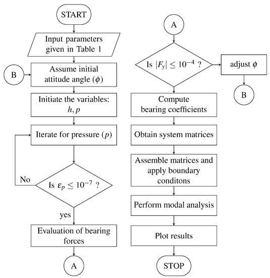
Figure 2.
Flowchart of computation.
4. Results and Discussion
Figure 3 shows a simple model of a rotor–shaft system studied in this work. It is a slightly modified rotor obtained from Rao [17]. The model consists of a flexible shaft mounted on identical journal bearings at the ends. A disc of mass is mounted at the centre of the shaft of length . The effect of bearing wear is studied for three different cases of worn bearings with (i) , (ii) , and (iii) , in addition to smooth bearing. The data used in the computation is provided in Table 1. The correctness of the present results is validated with the published work of Tsai and Jeng [8]. A comparison of the coefficient of friction is shown in Figure 4. It can be seen that results are in good agreement, which verifies the correctness of the present results.
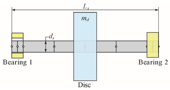
Figure 3.
Rotor-bearing system supported on identical journal bearings.

Table 1.
Input data.
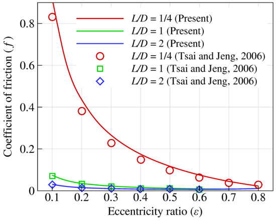
Figure 4.
Comparison of present results with published work of Tsai and Jeng [8].
For a particular rotor spin speed under steady-state conditions, the journal centre takes a position inside the bearing, which is quantified by the eccentricity e and the variation in eccentricity ratio with rotor spin speed, and is shown in Figure 5. As the speed increases, the journal centre comes closer to the bearing centre, resulting in a smaller eccentricity ratio. This is observed for all the four cases shown in Figure 5. The variation in attitude angle with journal speed is shown in Figure 6. It can be seen that the attitude angle increases with increasing speed implying that journal centre moves away from the vertical load line. Moreover, there is a decrease in attitude angle with bearing wear. Bearing wear has a significant influence on journal eccentricity, and as the wear depth is increased, there is a wider clearance gap and the journal settles farther from the bearing centre. The steady-state positions of the journal centre for different eccentricity ratios and wear depths are depicted in Figure 7. The position of the journal centre shifts towards the vertical line passing through the bearing centre as wear increases. At very high eccentricity (which corresponds to very low speed), the journal tends to settle near the bottom of the bearing. However, with the worn condition, the journal finds some extra space in the worn region, and due to hydrodynamic action, it shifts slightly to the right. This increases with increased wear depth and can be seen in Figure 7. Fillon and Bouyer [24] found similar results for oil-lubricated worn journal bearings.
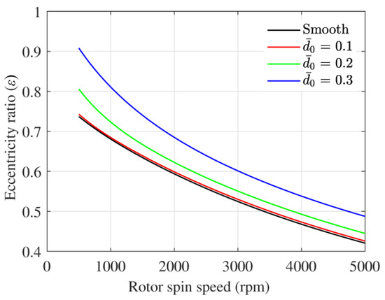
Figure 5.
Eccentricity ratio variation with rotor spin speed.
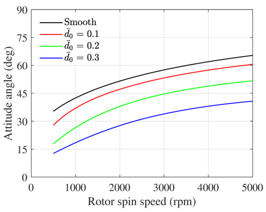
Figure 6.
Attitude angle variation with rotor spin speed.
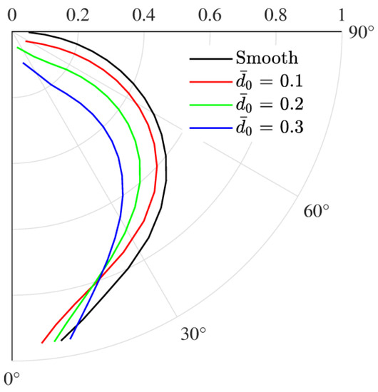
Figure 7.
Steady-state position of journal centre.
The film thickness and pressure profile at the bearing mid-plane for different worn conditions and speeds are shown in Figure 8. Film thickness modifies according to wear profile, and pressure profile is subsequently affected resulting in changes in the overall dynamics. At lower speeds, pressure is concentrated near the minimum film thickness. With the increase in speed, pressure is more distributed along the circumference. Figure 9 shows the pressure contours of all the cases to have a better picture of the overall pressure distribution.
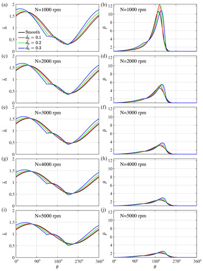
Figure 8.
Film thickness and pressure profile at the bearing mid-plane . (a) vs. at rpm, (b) vs. at rpm, (c) vs. at rpm, (d) vs. at rpm, (e) vs. at rpm, (f) vs. at rpm, (g) vs. at rpm, (h) vs. at rpm, (i) vs. at rpm, and (j) vs. at rpm.
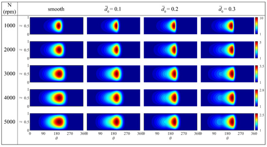
Figure 9.
Pressure contours on the unwrapped bearing surface for various speed and worn depth conditions.
To study the dynamic behaviour, it is important to evaluate the bearing coefficients since bearing coefficients play an important role in predicting the stability and vibration response of rotating machinery. The stiffness of a lubricant film primarily relies on its film thickness, where a thinner film results in a higher stiffness. The stiffness coefficient generally decreases as the speed increases due to the increase in film thickness. This is seen in Figure 10. The influence of bearing wear is also substantial because worn bearing influences the film thickness. With the increase in wear depth, the stiffness coefficient is seen to increase. Wear also influences the damping coefficients as shown in Figure 11.
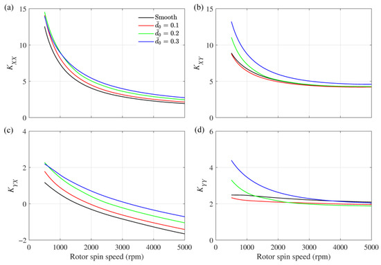
Figure 10.
Variation in the dimensionless stiffness coefficients, (a) , (b) , (c) , and (d) with rotor spin speed.
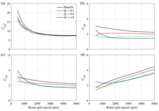
Figure 11.
Variation in the dimensionless damping coefficients, (a) , (b) , (c) , and (d) with rotor spin speed.
The Campbell diagram of four cases, (i) smooth bearing, (ii) , (iii) , and (iv) , are shown in Figure 12, wherein the whirl frequencies (imaginary part of the eigenvalues) for the first four modes are plotted against rotor spin speed. The synchronous whirl line (SWL) is also shown by a dashed line. The intersection of SWL with the whirl frequencies provides the critical speeds. The values of critical speeds and corresponding whirl frequencies are also indicated. In the subcritical region, which is on the left side of the critical speed, there are two whirl frequencies below the SWL. These are the whirl frequencies due to journal bearing and which increase with rotor spin speed. The whirl frequency corresponding to the first mode is approximately half of the rotor spin speed. The third and fourth whirl frequencies are above the SWL and represent the bending modes of the rotor. Bearing wear influences the whirl frequencies associated with bearing modes (I and II modes before veering, III and IV modes after veering). At a particular speed, there is a slight decrease in the whirl frequency associated with bearing modes. The whirl frequencies associated with shaft-bending modes are unaffected by bearing wear.
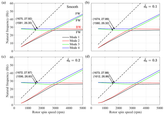
Figure 12.
Campbell diagram showing first four whirl frequencies vs. rotor spin speed for (a) smooth bearing, (b) bearing with , (c) bearing with , and (d) bearing with . (FW—Forward Whirl, BW—Backward Whirl).
Rotors generally exhibit two different kinds of whirling modes known as Forward Whirl (FW) and Backward Whirl (BW). In the subcritical region, the fourth mode is the BW mode, which is the bending mode of the rotor–shaft structure. The whirl frequency lines seem to cross one another after certain speeds, but in reality, they swap their trends, a phenomenon known as curve veering. The curve veering phenomenon is seen in the post-critical region, near approximately twice the critical speed. The veering near twice the critical speed is also seen in conventional oil-lubricated journal bearings supported rotor [37]. Mode shapes are obtained from eigenvectors obtained through eigenvalue analysis. Nodal values of x and y displacements are extracted from eigenvectors. These are generally complex values implying a rotation. These values are multiplied with coordinates of a unit circle in the transverse plane whose real parts are the coordinates of ellipses shown in Figure 13 [18]. The mode shapes corresponding to the first four modes are shown in Figure 13 for 2500 rpm and 3200 rpm spin speed of rotors, which are before veering and after veering. The swapping of mode shapes can be clearly seen in this figure.
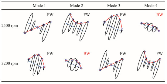
Figure 13.
Mode shapes of first four modes at rotor spin speed of 2500 rpm and of 3200 rpm for smooth bearing (FW—Forward Whirl, BW—Backward Whirl).
The variation of modal damping factors (MDF) of the first four modes with rotor spin speed is shown in Figure 14. A positive value of MDF implies a stable system as the energy of the system dissipates and a negative value of MDF implies an unstable system as the energy of the system increases through the whirling of the rotor. The onset of instability is defined by the stability limit speed (SLS), which is the rotor spin speed at which the MDF of any of the modes become negative. From Figure 12 and Figure 14, it may be noticed that the SLS is nearly twice the critical speed similar to what is seen in rotor supported by oil-lubricated journal bearings [37]. The modal damping factor in the case of powder-lubricated journal bearings is generally on the higher side as compared with oil-lubricated bearings.
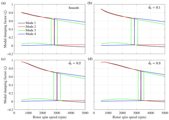
Figure 14.
Modal damping factor for first four modes vs. rotor spin speed for (a) smooth bearing, (b) bearing with , (c) bearing with , and (d) bearing with .
Figure 15 shows the critical speeds and SLS for the four cases. Critical speeds are almost unaffected by bearing wear because these are the natural frequencies associated with shaft-bending modes. However, SLS is increased with increased wear depth. The negatively cross-coupled stiffness coefficient tends to destabilize the system by providing a force in the direction of whirling. All other coefficients have positive values, which means their forces will act towards equilibrium and bring the journal towards equilibrium. Only becomes negative at higher speeds, which means a force will act on the journal that will move it away from the equilibrium position. Once this force becomes sufficiently high to balance all other forces, the journal will move away from the equilibrium, and thus, an unstable condition will arrive. As previously seen in Figure 10c, the value of becomes negative at a higher speed, for bearing with larger wear depth. Hence, rotors supported on bearings with larger wear depth are more stable.
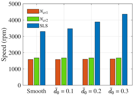
Figure 15.
Critical speed and stability limit speed (SLS) for different cases.
The unbalance response (UBR) at the location of disc is shown in Figure 16. There is a clear peak near the critical speed. The bearing wear has very slight influence on the unbalance response, and the amplitude is slightly increased with increased wear depth.
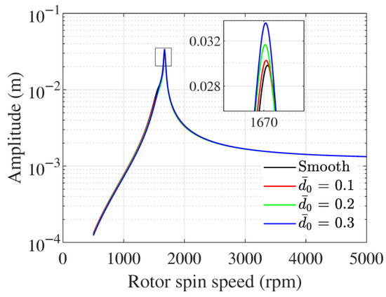
Figure 16.
Unbalance response at the location of the disc.
5. Conclusions
In this paper, a rotor supported on worn journal bearings lubricated with powders is analysed for stability and modal characteristics. The rotor–shaft system is discretized using finite element method, and an eigenvalue analysis is performed to determine its modal characteristics. The system matrices are dependent upon rotor spin speed; hence, whirling frequencies and mode shapes vary with speed too. There is a swapping of mode shapes near twice the critical speed. It is also found that with increased wear depth the eccentricity ratio increases, attitude angle decreases, and stiffness coefficients increase. Worn bearing increases the stability limit speed in comparison with smooth bearing. Bearing wear has a very insignificant influence on critical speeds and unbalance response. The amplitude of unbalance response increased only slightly with increased wear depth.
The present study is carried out considering the linearised bearing coefficients, and future studies will consider the non-linearities in the bearing and a transient analysis with varying speeds.
Author Contributions
Conceptualization, F.R.; Data curation, F.R.; Formal analysis, F.R. and E.M.; Investigation, F.R. and J.G.; Methodology, F.R. and E.M.; Resources, E.M. and J.G.; Software, F.R. and J.G.; Validation, F.R.; Writing—original draft, F.R.; Writing—review and editing, F.R., E.M., and J.G. All authors have read and agreed to the published version of the manuscript.
Funding
This research received no external funding.
Data Availability Statement
Not applicable.
Conflicts of Interest
The authors declare no conflict of interest.
References
- Wornyoh, E.Y.A.; Jasti, V.K.; Higgs III, C.F. A Review of Dry Particulate Lubrication: Powder and Granular. J. Tribol. 2007, 129, 438–449. [Google Scholar] [CrossRef]
- Heshmat, H. Tribology of Interface Layers; CRC Press, Taylor and Francis Group: Boca Raton, FL, USA, 2010. [Google Scholar]
- Rahmani, F.; Dutt, J.K.; Pandey, R.K. Performance Behaviour of Elliptical-Bore Journal Bearings Lubricated with Solid Granular Particulates. Particuology 2016, 27, 51–60. [Google Scholar] [CrossRef]
- Iordanoff, I.; Seve, B.; Berthier, Y. Solid Third Body Analysis Using a Discrete Approach: Influence of Adhesion and Particle Size on Macroscopic Properties. J. Tribol. 2002, 124, 530–538. [Google Scholar] [CrossRef]
- Haff, P.K. Grain Flow as a Fluid-Mechanical Phenomenon. J. Fluid Mech. 1983, 134, 401. [Google Scholar] [CrossRef]
- Dai, F.; Khonsari, M.M.; Lu, Z.Y. On the Lubrication Mechanism of Grain Flows. Tribol. Trans. 1994, 37, 516–524. [Google Scholar] [CrossRef]
- Tsai, H.-J.; Jeng, Y.-R. An Average Lubrication Equation for Thin Film Grain Flow With Surface Roughness Effects. J. Tribol. 2002, 124, 736–742. [Google Scholar] [CrossRef]
- Tsai, H.-J.; Jeng, Y.-R. Characteristics of Powder Lubricated Finite-Width Journal Bearings: A Hydrodynamic Analysis. J. Tribol. 2006, 128, 351–357. [Google Scholar] [CrossRef]
- Heshmat, H.; Brewe, D.E. Performance of a Powder Lubricated Journal Bearing With WS2 Powder: Experimental Study. J. Tribol. 1996, 118, 484–491. [Google Scholar] [CrossRef]
- Higgs III, C.F.; Tichy, J. Effect of Particle and Surface Properties on Granular Lubrication Flow. Proc. Inst. Mech. Eng. Part J J. Eng. Tribol. 2008, 222, 703–713. [Google Scholar] [CrossRef]
- Higgs III, C.F.; Tichy, J. Granular Flow Lubrication: Continuum Modeling of Shear Behavior. J. Tribol. 2004, 126, 499–510. [Google Scholar] [CrossRef]
- Sawyer, W.G.; Tichy, J. Lubrication With Granular Flow: Continuum Theory, Particle Simulations, Comparison With Experiment. J. Tribol. 2001, 123, 777–784. [Google Scholar] [CrossRef]
- Meng, F.; Liu, K.; Wang, W. The Force Chains and Dynamic States of Granular Flow Lubrication. Tribol. Trans. 2015, 58, 70–78. [Google Scholar] [CrossRef]
- Wang, W.; Gu, W.; Liu, K.; Wang, F.; Tang, Z. DEM Simulation on the Startup Dynamic Process of a Plain Journal Bearing Lubricated by Granular Media. Tribol. Trans. 2014, 57, 198–205. [Google Scholar] [CrossRef]
- Wang, W.; Gu, W.; Liu, K. Force Chain Evolution and Force Characteristics of Shearing Granular Media in Taylor-Couette Geometry by DEM. Tribol. Trans. 2015, 58, 197–206. [Google Scholar] [CrossRef]
- Irretier, H. Mathematical Foundations of Experimental Modal Analysis in Rotor Dynamics. Mech. Syst. Signal Process. 1999, 13, 183–191. [Google Scholar] [CrossRef]
- Rao, J.S. Rotor Dynamics; New Age International (P) Ltd.: Delhi, India, 1996. [Google Scholar]
- Friswell, M.I.; Penny, J.E.; Garvey, S.D.; Lees, A.W. Dynamics of Rotating Machines; Cambridge University Press: Cambridge, UK, 2010. [Google Scholar]
- Qiu, Z.L.; Tieu, A.K. The Effect of Perturbation Amplitudes on Eight Force Coefficients of Journal Bearings. Tribol. Trans. 1996, 39, 469–475. [Google Scholar] [CrossRef]
- Rahmani, F.; Dutt, J.K.; Pandey, R.K. Stability of Rotor Supported on Powder Lubricated Journal Bearings with Surface Pockets. Proc. IMechE Part C J. Mech. Eng. Sci. 2021, 235, 2317–2329. [Google Scholar] [CrossRef]
- El-Shafei, A.; Tawfick, S.H.; Raafat, M.S.; Aziz, G.M. Some Experiments on Oil Whirl and Oil Whip. In ASME Turbo Expo 2004: Power for Land, Sea, and Air, Proceedings of the Turbo Expo 2004, Vienna, Austria, 14–17 June 2004; ASME: New York, NY, USA, 2008; Volume 6, pp. 701–710. [Google Scholar] [CrossRef]
- Dufrane, K.F.; Kannel, J.W.; McCloskey, T.H. Wear of Steam Turbine Journal Bearings at Low Operating Speeds. J. Lubr. Technol. 1983, 105, 313–317. [Google Scholar] [CrossRef]
- Hashimoto, H.; Wada, S.; Nojima, K. Performance Characteristics of Worn Journal Bearings in Both Laminar and Turbulent Regimes. Part I: Steady-State Characteristics. ASLE Trans. 1986, 29, 565–571. [Google Scholar] [CrossRef]
- Fillon, M.; Bouyer, J. Thermohydrodynamic Analysis of a Worn Plain Journal Bearing. Tribol. Int. 2004, 37, 129–136. [Google Scholar] [CrossRef]
- Papadopoulos, C.A.; Nikolakopoulos, P.G.; Gounaris, G.D. Identification of Clearances and Stability Analysis for a Rotor-Journal Bearing System. Mech. Mach. Theory 2008, 43, 411–426. [Google Scholar] [CrossRef]
- Gertzos, K.P.; Nikolakopoulos, P.G.; Chasalevris, A.C.; Papadopoulos, C.A. Wear Identification in Rotor-Bearing Systems by Measurements of Dynamic Bearing Characteristics. Comput. Struct. 2011, 89, 55–66. [Google Scholar] [CrossRef]
- Chasalevris, A.C.; Nikolakopoulos, P.G.; Papadopoulos, C.A. Dynamic Effect of Bearing Wear on Rotor-Bearing System Response. J. Tribol. 2013, 135, 011008. [Google Scholar] [CrossRef]
- Machado, T.H.; Cavalca, K.L. Modeling of Hydrodynamic Bearing Wear in Rotor-Bearing Systems. Mech. Res. Commun. 2015, 69, 15–23. [Google Scholar] [CrossRef]
- Machado, T.H.; Mendes, R.U.; Cavalca, K.L. Directional Frequency Response Applied to Wear Identification in Hydrodynamic Bearings. Mech. Res. Commun. 2016, 74, 60–71. [Google Scholar] [CrossRef]
- Machado, T.H.; Alves, D.S.; Cavalca, K.L. Investigation about Journal Bearing Wear Effect on Rotating System Dynamic Response in Time Domain. Tribol. Int. 2019, 129, 124–136. [Google Scholar] [CrossRef]
- König, F.; Ouald Chaib, A.; Jacobs, G.; Sous, C. A Multiscale-Approach for Wear Prediction in Journal Bearing Systems—From Wearing-in towards Steady-State Wear. Wear 2019, 426–427, 1203–1211. [Google Scholar] [CrossRef]
- Gecgel, O.; Dias, J.P.; Ekwaro-Osire, S.; Alves, D.S.; Machado, T.H.; Daniel, G.B.; de Castro, H.F.; Cavalca, K.L. Simulation-Driven Deep Learning Approach for Wear Diagnostics in Hydrodynamic Journal Bearings. J. Tribol. 2020, 143, 084501. [Google Scholar] [CrossRef]
- Mokhtari, N.; Pelham, J.G.; Nowoisky, S.; Bote-Garcia, J.L.; Gühmann, C. Friction and Wear Monitoring Methods for Journal Bearings of Geared Turbofans Based on Acoustic Emission Signals and Machine Learning. Lubricants 2020, 8, 29. [Google Scholar] [CrossRef]
- König, F.; Sous, C.; Ouald Chaib, A.; Jacobs, G. Machine Learning Based Anomaly Detection and Classification of Acoustic Emission Events for Wear Monitoring in Sliding Bearing Systems. Tribol. Int. 2021, 155, 106811. [Google Scholar] [CrossRef]
- Rahmani, F.; Pandey, R.K.; Dutt, J.K. Performance Studies of Powder-Lubricated Journal Bearing Having Different Pocket Shapes at Cylindrical Bore Surface. J. Tribol. 2018, 140, 031704. [Google Scholar] [CrossRef]
- Meirovitch, L. Fundamentals of Vibrations; Waveland Press: Long Grove, IL, USA, 2010. [Google Scholar]
- Chouksey, M.; Dutt, J.K.; Modak, S.V. Modal Analysis of Rotor-Shaft System under the Influence of Rotor-Shaft Material Damping and Fluid Film Forces. Mech. Mach. Theory 2012, 48, 81–93. [Google Scholar] [CrossRef]
Disclaimer/Publisher’s Note: The statements, opinions and data contained in all publications are solely those of the individual author(s) and contributor(s) and not of MDPI and/or the editor(s). MDPI and/or the editor(s) disclaim responsibility for any injury to people or property resulting from any ideas, methods, instructions or products referred to in the content. |
© 2023 by the authors. Licensee MDPI, Basel, Switzerland. This article is an open access article distributed under the terms and conditions of the Creative Commons Attribution (CC BY) license (https://creativecommons.org/licenses/by/4.0/).