Article

Study on the Influence of Micro-Features in the Surface Topography of the Slider Raceway on the Dynamic Friction Factor of the Guide Rail Pair

School of Mechanical and Electrical Engineering, China University of Mining and Technology, Xuzhou 221116, China
*
Author to whom correspondence should be addressed.
Lubricants 2023, 11(8), 321; https://doi.org/10.3390/lubricants11080321
Submission received: 19 June 2023 / Revised: 25 July 2023 / Accepted: 26 July 2023 / Published: 28 July 2023

Abstract

:
During the operation of the guide rail pair, the accuracy of the guide rail pair is decreased by friction and wear, and the overall performance of the machine tool is directly affected. The influence of surface micro-features of the slider raceway on the dynamic friction factor of the guide rail pair is analyzed in this paper. The relationship between the geometric characteristics of the surface micro-features and the dynamic friction factor is studied, and a prediction model of the dynamic friction factor is established. Meanwhile, the correctness and rationality of the predicted model is verified by the orthogonal experiments of the friction force. It is found that the dynamic friction factor increases with the increase of the groove depth, the height of the peaks and peak–valleys on the surface of the slider raceway. The above research provides a basis for the study of the friction and wear characteristics of guide rail pairs and lays a foundation for improving its friction and wear performance.

1. Introduction

During the operation of the guide rail pair, friction is the main mode of energy loss, and its changes will affect the stability of the guide rail pair. In addition, its surface material will gradually wear and tear off during the operation of the guide rail pair. At this time, the adhesion mechanism or abrasive wear mechanism will cause wear, leading to a decrease in the guiding accuracy and contact stiffness of the guide rail pair, affecting its accuracy maintenance and reducing its functional reliability and service life. Therefore, the service life and working stability of the linear guide pair are mainly determined by its friction and wear characteristics. In addition to changing the material, another effective method to improve the anti-friction and wear characteristics of the linear guide pair is to improve the surface quality of the raceway. Therefore, it is urgent to conduct research on the influence mechanism of the surface quality of raceways on their friction and wear characteristics.
At present, there is much research on the influence of surface micro-features on the surface friction performance. The effects of dimples on a surface were first reported by Etsion et al. [1,2,3], who investigated the effect of surface texturing and the optimal geometric arrangement of the surface features. They found that surface texturing substantially increased the load-carrying capacity of bearing surfaces. Menezes et al. [4] studied the effects of surface roughness and textures on the coefficient of friction. It was observed that the coefficient of friction depended primarily on the surface texture of hard surfaces but is independent of the surface roughness of hard surfaces. However, they only examined the effect of the existence of dimples and did not investigate their geometry. Kim et al. [5] used a laser beam to create small pits of different sizes on the surface of gray cast iron, and their effects on the friction behavior of automobile engine surface were studied. Their results found that the aspect ratio of the dimples was the most significant factor, while the effect of the surface density of the dimples on the coefficient of friction was marginal. Costa et al. [6] researched the influence of the surface topography of the workpiece sample and the steel ball on the dynamics of wear particles in the micro-wear process. It was found that the effect of the topography of the specimens on wear coefficients and mechanisms was much less pronounced than that found for the ball topography. Wakuda et al. [7] verified the effect of micro-dimples on the frictional properties of a silicon nitride ceramic combined with hardened steel. Compared to a lapped smooth surface without texturing, some samples successfully realized reductions in the friction coefficient from 0.12 to 0.10. It was found that the tribological characteristics depended greatly on the size and density of the micro-dimples and not the dimple shape. At the same time, Magnus et al. [8] studied the feasibility of using a laser surface texture (LST) to improve the tribological properties of Ti3SiC2MAX phase composites. The test results showed that both the line- and square-textured MAX phase composite surface exhibited excellent wear performance as well as a reduction in friction. Grabon et al. [9] studied the influence of cylinder liner surface morphology on low temperature friction and wear of a cylinder liner ring system. It was found that two process textures tested at the low temperature led to a smaller final coefficient of friction, compared to one process surface; the opposite results were obtained at a high temperature. Yang et al. [10] studied the influence mechanism of volcanic texture on the tribological behavior of textured coating surface. The results showed a volcano-shaped texture with a suitable diameters and area ratios which were conducive to lowering the friction coefficient and reducing adhesive wear. The optimal texture diameter and area ratio were 310 μm and 25%, respectively. Wang et al. [11] analyzed the change of surface topography characteristics of 2219 aluminum alloy under different wear conditions. The results showed that tool wear led to the confusion of the weld texture profile and the appearance of the local burr. Pei et al. [12] studied the evolution of the surface topography and friction coefficient during sliding wear in a mixed-lubrication rolling–sliding contact based on the numerical approach developed by Zhu et al. [13]. The results showed that the RMS roughness deceased slightly at first, and then it increased gradually during the wear process. Saeidi et al. [14] researched the influence of five geometrical texture parameters (feature depth, diameter, length, area fraction and sliding direction) and their interactions on friction coefficient and workpiece life. It was found that except for the main factors of diameter and area fraction, the main interactions of geometrical parameters had a significant impact on the coefficient of friction. Yu et al. [15] established an analysis model from the geometric shape and distribution of the pits and evaluated the hydrodynamic effect of the pit mode and the antifriction effect under high and low speed load conditions. The results suggested the shallow and small dimples would have had a more obvious friction reduction effect for the case of low-speed and high-load conditions. Braun et al. [16] studied the influence of dent diameter, dent edge and dent size on surface friction under the condition of mixed lubrication. It was found that the dimple diameters leading to the highest friction reduction significantly depend on the oil temperature. Segu and Kim [17] analyzed the influence of the surface of steel with multiple pits on the tribological properties and the optimization effect of different pit density on the tribological properties. The results indicated that the surface with multi-dimple textured patterns had better friction performance than the untextured and single-dimple textured surfaces. Nakano et al. [18] investigated the relationship between texture geometry and coefficients of friction by testing micro-textured surfaces prepared by shot blasting. The results indicated that the surfaces with dimpled patterns had lower friction coefficients than the flat surfaces and the dimpled pattern had a beneficial effect by decreasing the friction. Ren et al. [19] conducted numerical analyses to determine the effect of the distribution of shallow dimples on the tribological properties of a surface. The results indicated that the textures generating the strongest hydrodynamic lifting are short grooves with a small aspect ratio and sinusoidal waves of a small wavelength/amplitude ratio propagating in the motion direction. Andersson et al. [20] studied the influence of a laser-textured tool surface with a concave size and geometric shape on friction and wear. Wang et al. [21] studied the influence of four morphologies of hemispherical, conical, ellipsoidal and wedge-shaped pits on the friction properties of CFRPEEK. From the experimental results, the ellipsoidal pit CFRPEEK samples exhibited the best tribological properties and better wettability.
Despite many scholars have conducted numerous studies on the influence of surface micro-features on friction and wear characteristics, that research is mainly applied to sliding friction but rarely applied to rolling friction especially in the study of rolling linear guide pairs. At present, the research of roller linear guide pairs is mainly focused on stiffness, static characteristics, dynamic characteristics, rated static load, rated dynamic load, etc. [22,23,24,25]. Some scholars have also studied the friction characteristics of rolling linear guide pairs. For example, Oh et al. [26]. Established an explicit friction model for ball contact rolling linear guide pairs from the material, geometric parameters, assembly and operating conditions of the guide pairs. It was found that the magnitude of friction depends on factors such as the size and contact angle of the ball. Cheng et al. [27] proposed an improved calculation model for calculating friction force by considering the geometric parameters of rolling elements, contact force and the changing in the viscosity of lubricating grease with pressure and temperature. Zhang et al. [28] studied the variation of frictional force with normal contact angle and preload based on Hertz theory and established a frictional force model for rolling linear guide pairs considering elastohydrodynamic lubrication. Wang et al. [29] proposed a mathematical model for the friction force and preload of the roller linear guide pair, but only four different interference levels of the roller linear guide pair were measured for friction force due to the lack of preload adjustment devices.
From this, it can be seen that there is very little research on the impact analysis of the application of micro-feature information from the surface topography to the friction characteristics of the roller linear guide pair. Most of the existing research on friction characteristics of guide pairs is based on macro-parameter characteristics such as external load, contact force and rolling element size. And most of the research mainly relies on the overly simplified mechanical models or wear theories, which lack the study of basic theories. Meanwhile, during the operation of the guide rail pair, the rolling friction between the contact surfaces is caused by the mechanical deformation resistance and molecular adhesion resistance. They are generated by the meshing, collision and elastic-plastic deformation between the micro-convex bodies on the surface of the raceway. It is also accompanied by phenomena such as plastic extrusion, adhesive wear and abrasive wear of the surface micro-convex materials [30]. Surface micro-features exist in the three-dimensional (3D) surface topography, similar to workpiece fingerprints, which are common but different. Compared with the two-dimensional (2D) parameter roughness, the surface quality can be better comprehensively characterized by the distribution and size of surface micro-features such as convex peaks, pits and peak–valley structures obtained from the 3D surface topography. The influence mechanism of the surface quality of the raceway on its friction factor can be fundamentally analyzed from the perspective of surface micro-features in comparison to traditional calculation methods of the friction factor. Therefore, the geometric characteristics of the surface micro-features can be extracted from the surface topography of the slider raceway. And the prediction model of dynamic friction factor is established by quantifying the relationship between the geometric characteristics of groove, crest and valley and the dynamic friction factor of the guide rail pair. And the influence of surface micro features on the dynamic friction factor is analyzed.

2. Mathematical Model

The roller linear guide pair is generally not used alone in the working process. It is usually four in a group or more and carries the reciprocating linear motion of the working platform. In addition to the driving force, the guide rail pair will generally be loaded in other directions, such as the worktable weight, the cutting force or grinding force in the machining process of the workpieces and the inertia force in the high-speed movement process. Meanwhile, it will also have a torque effect on the guide rail pair due to the uneven stress of the working platform. In this paper, the mechanical model mainly corresponds to the state of the guide rail pair on the friction and wear tester; that is, a single slider is installed on a single guide rail. Therefore, the force model of the guide rail pair can be simplified by ignoring the torque, and the slider is only subjected to the positive pressure load, as shown in Figure 1.

2.1. Friction Model of Guide Pair under Positive Pressure Load P

As shown in Figure 1a, only two rows of rollers 3 and 4 are stressed under the positive pressure load P when there is no preload during the assembly of the slider. Assuming that the pressure angle of the guide rail pair is α and there are n rollers in each row, the force on the j -th roller in the i -th row is as follows:
F i j = P / ( 2 n cos α )   ( i = 1 , 2 , 3 , 4 .   j = 1 , 2 , , n )
The friction force of the linear guide rail pair without preload during uniform motion is as follows:
F = i = 3 4 j = 1 n F i j = P cos α μ 0
where μ 0 is the dynamic friction coefficient during roller rolling.
As shown in Figure 1b, each ball in the four rows of rollers is stressed when the preload is set during the assembly of the slider; that is, each roller generates friction. Based on the contact angle α between the roller and the raceway, the relationship between the normal unilateral deformation δ n of the guide rail pair and the vertical deformation δ of the slider is as follows:
δ = 2 δ n / cos α
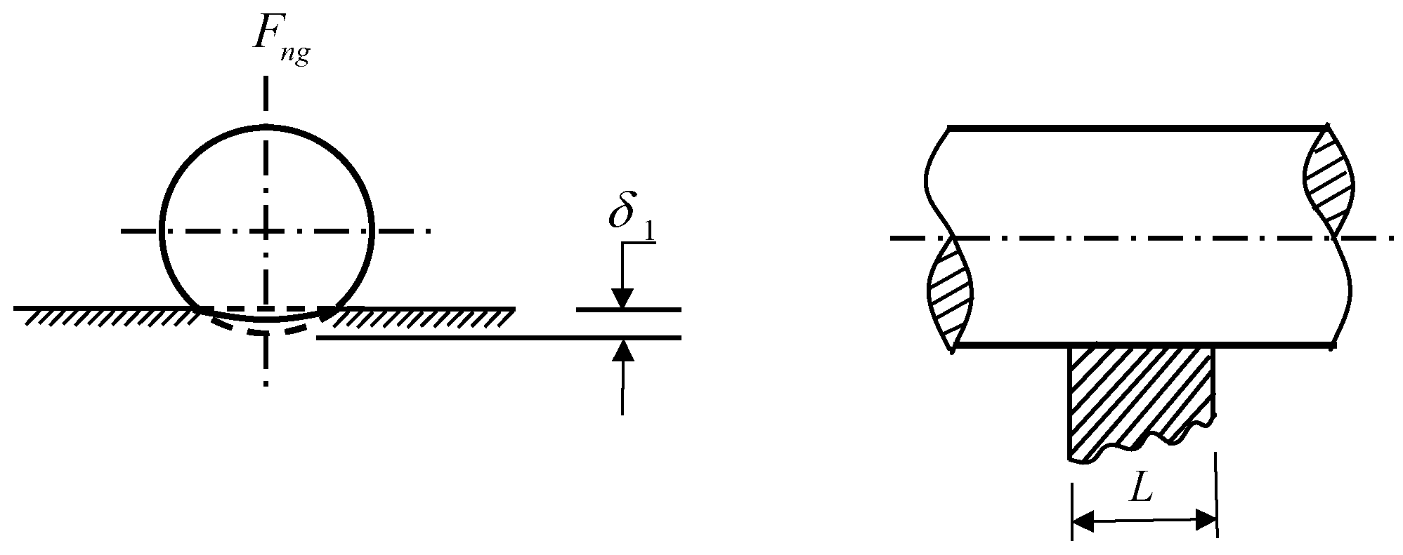
For the load range normally used in the metrology field, Norden, B. N. [31] Proposed the best approximation to the compression obtained between a cylinder and flat (Figure 2 [31]). Based on the finiterectangle approach, it is as follows:
δ 1 = F n g L ( λ 1 + λ 2 ) [ 1 + ln L 3 ( λ 1 + λ 2 ) F n g R ]
λ i = 1 υ i 2 π E i
where F n g is the measuring force, and it is equal to F i j . L is the contact length between cylinder and plane, and it is the height of the roller. R is the radius of roller. v i and E i are the Poisson’s ratio and Young’s modulus of the roller or the guide rail, respectively.
Combined with Equations (1) and (3)–(5), the relationship between roller deformation and force can be deduced:
δ = P ( λ 1 + λ 2 ) n cos 2 α L [ 1 + ln L 3 2 n cos α ( λ 1 + λ 2 ) R P ]
Equation (6) can be simplified into P = f ( δ ) .
The preload of the slider is realized by setting the interference size between the roller and the raceway, and the vertical forces generated by the first and second rows of rollers and the third and fourth rows of rollers are F 1 and F 3 , respectively, according to the simplified formula of P :
F 1 = f ( δ n δ cos α 2 ) n
F 3 = f ( δ n + δ cos α 2 ) n
Equation (7) is valid on the premise that the preload force must be greater than half of the positive load of the slider; that is, the preload does not fail. Thus, the friction force under external load and preload of slider can be obtained as follows:
P = 2 ( F 1 + F 3 ) cos α
F = 2 ( F 1 + F 3 ) μ 0
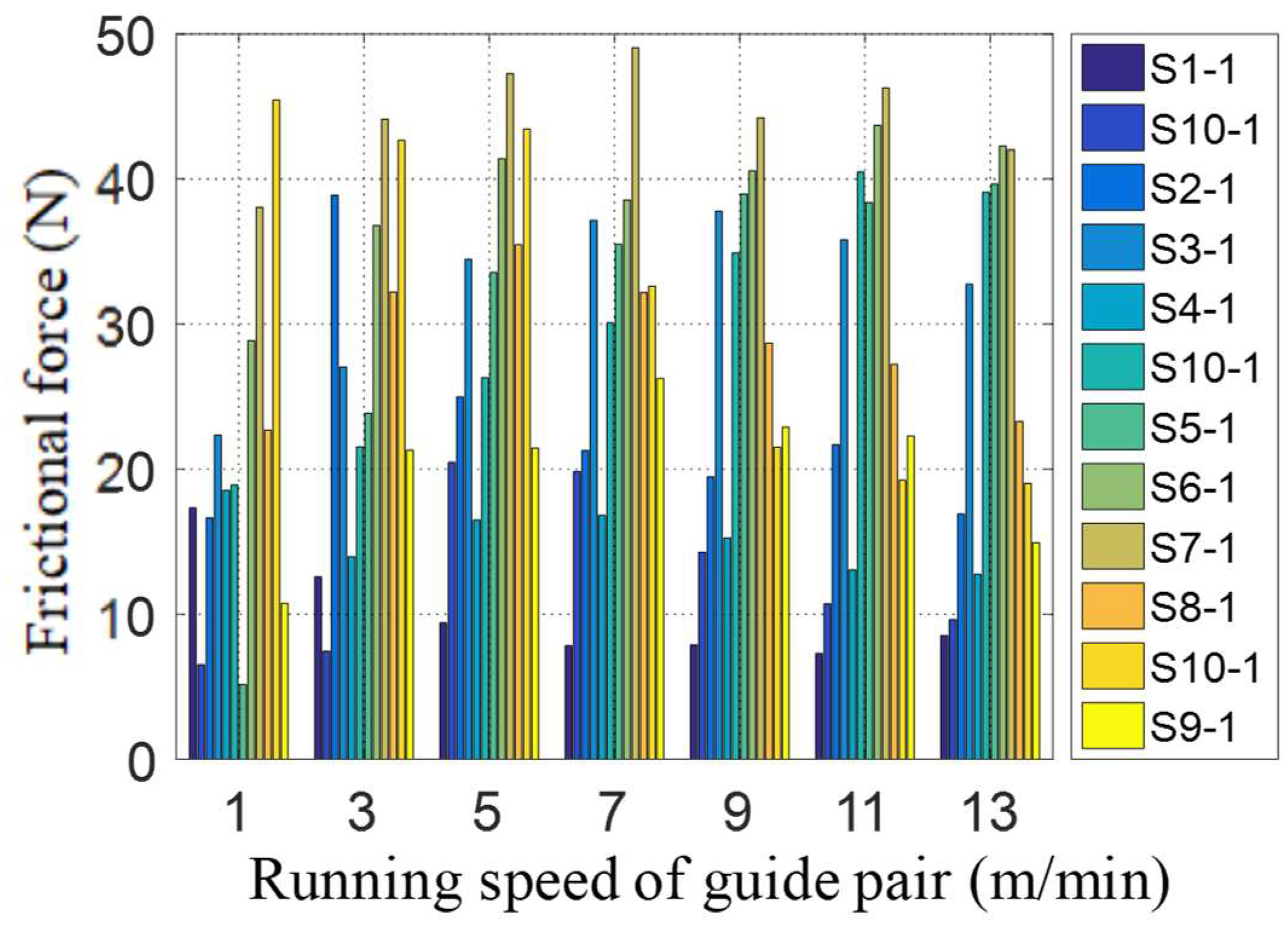
According to the friction model in Equations (2)–(10), when there is no preload or the positive load is more than twice of the preload (i.e., the preload fails), the friction increases with the increase of slider’s positive load, and the dynamic friction factor remains unchanged. However, this is not completely consistent with the actual measurement. The friction force of the guide rail pairs assembled by sliders (S1-1~S10-1) under the conditions of no slider preload, the same external load (4630 N) and different operating speeds is shown in Figure 3. These sliders are with different surface topographies and roughness ground with different grinding depths, feeding speeds and linear speeds. It is obvious that the friction force varies with different topographies of the slider raceway. The surface roughness of each slider (S1-1~S10-1) in the legend of Figure 3 is 0.19 μm, 0.29 μm, 0.33 μm, 0.22 μm, 0.28 μm, 0.31 μm, 0.32 μm, 0.29 μm, 0.23 μm and 0.25 μm,. It can be seen that the dynamic friction factor of the linear guide pair is not constant during operation, and its size is closely related to the surface roughness of the raceway.
In addition to the influence of the external load on the friction force of guide rail pair, the change of structural parameters such as roller diameter, interference of guide rail pair and the deviation of horizontal or vertical installation of guide rail have different effects on the friction force or dynamic friction factor of the guide rail pair. Therefore, it is assumed that the roller diameter of the slider is unchanged, the interference of the guide pair is 0, and the guide rail installation error is a constant value when the dynamic friction factor prediction model of GZB45BA roller linear guide pair is established. The initial shape of the contact surfaces is assumed to be ideal. The intermediate change in the shape of the contacting surfaces is not take into account. And for determining the magnitude of pressure on the sections of the surface, local elastic deformations of the guide also are not taken into account. Based on the above assumptions, the dynamic friction factor prediction model of the guide rail is established. And the influence of the geometric characteristics and distribution of the groove, crest and peak–valley microstructures in the surface topography of the slider raceway on the dynamic friction factor of the guide rail pair is mainly studied in this paper.

2.2. Dynamic Friction Factor Prediction Model of the Guide Rail

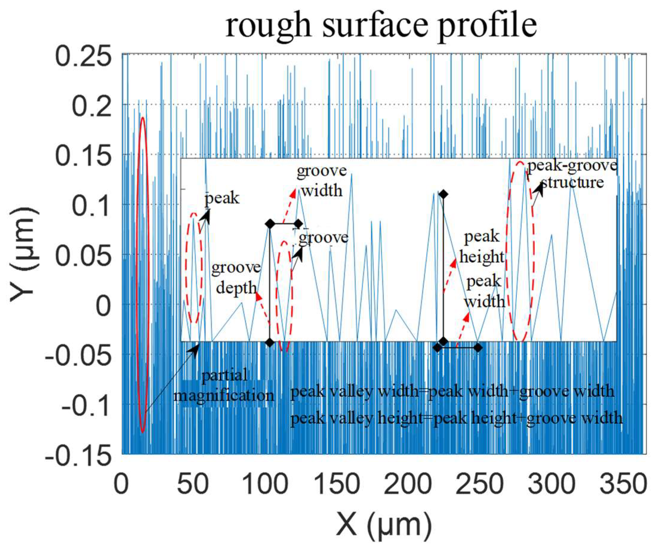
The geometric characteristics of surface micro-features refer to the width, depth, height and aspect ratio of pits, convex peaks and peak–valley structures in the surface topography of the slider raceway. From the 3D surface topography of the slider raceway (Figure 6 in Section 3.1), the surface roughness profile can be extracted. In addition, the characteristic information of surface micro-feature such as groove and convex peak in the topography can be obtained according to the surface roughness profile, as shown in Figure 4.
Assuming that the roughness profile has n convex peak structure and m groove structure, respectively, then the geometric feature dimensions of the groove, convex peak and peak–valley structures are calculated as follows:
{ A S j = min ( y j 1 , y j + 1 ) y j    ( j = 1 , , m ) A W j = 2 ( x j x min ( y j 1 , y j + 1 ) )   ( j = 1 , , m ) A S W j = A S j / A W j    ( j = 1 , , m ) T H i = y i y i 1    ( i = 1 , , n ) T W i = x i x i 1    ( i = 1 , , n ) T H W i = T H i / T W i    ( i = 1 , , n )   F G H i = T H i + A S j    ( i = 1 , , min ( n , m ) ) F G W i = T W i + A W j    ( i = 1 , , min ( n , m ) )
where AS, AW, ASW, TH, TW, THW, FGH and FGW are the groove depth, width, depth to width ratio, convex peak height, width, height to width ratio and the height and width of the peak–valley structure, respectively, and the unit is μm.
To facilitate the study of the influence mechanism of surface micro-feature characteristics on the dynamic friction factor, statistical analysis is needed where AS, AW, ASW, TH, TW, THW, FGH and FGW are the mean values of the groove depth, width, depth width ratio, convex height, width, height width ratio and the average height and width of the peak–valley structure of the three sliders in each group (μm), respectively. The calculation is as follows:
{ A S ¯ = j = 1 m [ min ( y j 1 , y j + 1 ) y j ] / m A W ¯ = j = 1 m [ 2 ( x j x min ( y j 1 , y j + 1 ) ) ] / m A S W ¯ = A S ¯ / A W ¯ T H ¯ = i = 1 n ( y i y i 1 ) / n   T W ¯ = i = 1 n ( x i x i 1 ) / n   T H W ¯ = T H ¯ / T W ¯ F G H ¯ = T H ¯ + A S ¯   F G W ¯ = T W ¯ + A W ¯
To quantitatively analyze the influence of the surface topography on the dynamic friction force of the guide rail pair, the 2D roughness and the geometric characteristics of the grooves, peaks and valleys are extracted according to the 3D topography shown in Figure 6 in Section 3.1. The results are shown in Table 1. μ0 is the average value of dynamic friction factor obtained from five repeated test measurements. Ra is the mean value of the 2D roughness of each slider, and its unit is μm. And it is determined by the mean of the 2D roughness values of the extracted roughness contour lines at five different positions in the surface topography of the slider, as shown in Figure 5. And the roughness in all tables and figures in the paper is linear roughness (Ra).
Surface roughness refers to the smaller spacing and the unevenness of the small peaks and valleys on the machined surface [32]. It is highly dependent on the size and distribution of grooves and protrusions. When the material and operating conditions of the guide rail are fixed, surface roughness plays a major role in the influencing factors of the dynamic friction factor. Within the commonly used range of amplitude parameters related to surface roughness evaluation, the arithmetic mean deviation (Ra) of the contour is preferred. Ra is the arithmetic mean of the absolute values of the contour offset within the sampling length. According to the definition of Ra, it is a design for linear (2D) parameters. As it is a mean calculation, it is difficult to reflect the different effects of micro-features such as grooves and peaks on the friction coefficient.
To study the influence of surface quality on dynamic friction factor in more detail, a prediction model for dynamic friction factor is established in this article from the perspective of surface micro-features. Therefore, to avoid repetition, it is not necessary to consider Ra again when a prediction model for the dynamic friction factor is established by considering the effects of the depth, height, width and aspect ratio of pits, convex peaks and peak–valley structures on the dynamic friction factor.
The average values of groove depth AS, width AW, depth-to-width ratio ASW, convex peak height TH, width TW, height-to-width ratio THW, height-to-valley structure height FGH and width FGW in Table 1 are independent variables, and the average of the dynamic friction factors μ0 is used as the dependent variable, and the nlinfit fitting function in Matlab is used for functional relationship solving. The fitting result is as follows:
μ 0 ¯ = 0.2799 + 0.0489 A S ¯ 0.4854 A W ¯ 4.5029 × 10 4 A S W ¯ + 0.1626 T H ¯ 0.5620 T W ¯ + 0.0065 T H W ¯ 0.1024 F G H ¯ + 0.9785 F G W ¯
It can be seen from Equation (13) that the groove depth AS, the height of the convex peak TH, the height–width ratio of the convex peak THW and the width of the peak–valley structure FGW are positively correlated with the dynamic friction factor μ0. The groove width AW, the groove aspect ratio ASW, the peak width TW and the height of the peak–valley structure FGH are negatively correlated with the kinetic friction factor μ0. Among them, the width of the peak–valley structure FGW has the greatest influence on the dynamic friction factor μ0, followed by the groove width AW and the width of the peak structure TW, while the groove aspect ratio ASW and the peak height–width ratio THW have minimal impact. Substituting the surface micro-feature geometric characteristics of each slider in Table 1 into Equation (13), the residual between the estimated value and experimental value of the kinetic friction factor is obtained. As shown in Table 1, the residual variance is 2.2950 × 10⁻⁸. The groove aspect ratio ASW and the peak height–width ratio THW have a non-independent relationship with the groove depth AS, width AW and the height of the peak TH and width TW. The groove aspect ratio ASW and peak aspect ratio THW in Equation (13) have little effect on the dynamic friction factor. In addition, it can be found from Table 1 that the width of grooves, peaks and peak–valley structures on the raceway surface almost does not change with the surface roughness. Therefore, their mean values of 0.294, 0.294 and 0.588 can be substituted into Equation (13) to simplify the model. At the same time, taking only the height and width of grooves, convex peaks and peak–valley structures as independent variables, the simplified dynamic friction factor prediction model obtained by using the nlinfit fitting function is shown in Equation (14). Similarly, the geometric characteristics of the surface micro-features of each slider in Table 1 are substituted into Equation (14), and the residual variance between the estimated value and the experimental value of dynamic friction factor are 2.3268 × 10⁻⁸.
μ 0 ¯ = 0.011 + 0.0633 A S ¯ + 0.1715 T H ¯ 0.1004 F G H ¯
Therefore, Equation (14) can be used as the prediction model of the dynamic friction factor, and the model can be verified experimentally.

3. Experimental Research

3.1. Materials

In this paper, the slider in the O-type roller heavy load linear guide pair GZB45BA is selected as the research object, as shown in Figure 6, and the corresponding dimension parameters are shown in Table 2. The O-type roller linear guide pair is mainly composed of the slider, guide rail, roller, deflector, cage, etc. The contact angle between the roller of the guide pair and the raceway is 45°, which makes the roller linear guide pair have the characteristics of equal load in the upper, lower, left and right directions, and the four directions have ultra-high bearing capacity and rigidity.
The roller linear guide pair is mainly composed of slider, guide rails, rollers, deflectors, retainers, etc. It has the advantages of simple structure, low dynamic and static friction coefficient, high positioning accuracy and good accuracy retention. It is mainly used in heavy-duty combination machine tools such as machining centers, Computer Numerical Control (CNC) composite machining machines, high-precision electric discharge cutting machines, grinders, gantry machining centers, etc. It is especially suitable for high-end machine tools with high rigidity, high precision and overweight loads [22]. And its friction force is only 1/50 to 1/100 of that of the sliding guide rail. It reduces energy consumption and improves the positioning accuracy and mechanical device follow-up performance [33]. Compared to the point contact of ball type guide rail pairs, the straight and long line contact of roller linear guide rail pairs only forms small elastic deformation when the rollers bear high loads, making them have advantages such as high bearing capacity, high stiffness, low rolling friction, low wear and long service life.

3.2. Experiments

To research the effect of the surface micro-features on the dynamic friction factor of the guided rail pair, the grinding experiments of the slider raceway surface and the friction measurement experiments are conducted, respectively.
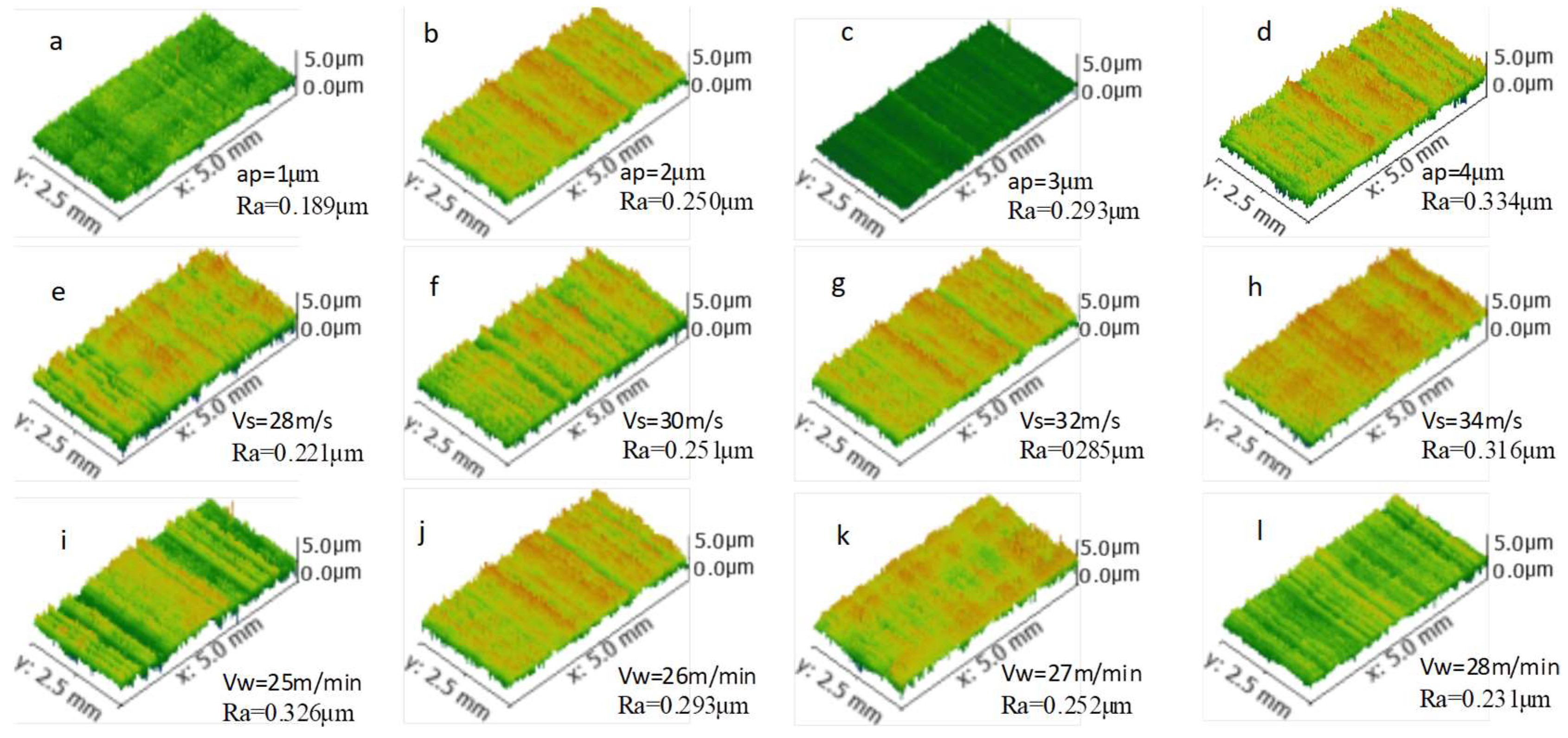
Firstly, the surface grinding experiment of the slider raceway is carried out on the slider grinder PLANMATH408 through the single factor test method. The specific experimental scheme is shown in Table 3. The Vw, Vs and ap in Table 3 are the grinding process parameters used to process the surface of the slider raceway, where Vw is the feed speed of the workpiece, Vs is the linear speed of the grinding wheel and ap is the grinding depth. The type of slider is GZB45BA, and its material is GCr15. The type of the grinding wheel is 1A46X25X13-SA100K35, and its material is alumina. The grinding fluid used during the slider grinding process is fully synthetic water-soluble cutting fluid. During the experiment, four identical sliders are ground at the same time to reduce experimental errors, which can also be as the repeated experiment. The surface topography of the slider raceway is measured by the Rtec dual focus 3D topography instrument (US and UP). The size of the testing area is 5 mm on the x-axis and 2.5 mm on the y-axis. The resolution of the x-axis and y-axis is 0.1 μm, and the resolution of the z-axis is 0.01 μm. During the surface topography testing process of each slider, there are more than seven different areas that are selected for measurement. When the roughness of the measurement area is repeated more than five times with the roughness of other areas, it can be used as a representative area for analysis. The results are shown in Figure 7 in Section 4. From this, the geometric characteristics of surface micro-features such as peaks, pits and peak–valleys can be extracted to be used for the model establishment of the dynamic fraction factor.
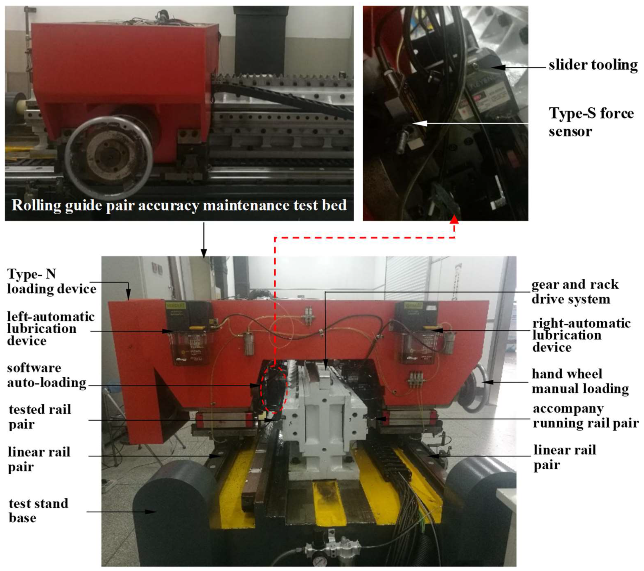
Secondly, the friction testing experiments on linear guide pairs with different surface topographies of slider raceways are conducted on the roller guide rail precision retention test bench (provided by Nanjing Process Equipment Co., Ltd.), as shown in Figure 7. The experimental conditions are that the guide rail pair has no slider preload, the same external load and different operating speeds (1 m/min, 3 m/min, 5 m/min, 7 m/min, 9 m/min, 11 m/min and 13 m/min). The principle of friction testing is shown in Figure 8. The N-type loading device of the test bench is divided into the left and right loading systems. The right side is manually loaded with a handwheel. When the load is too large, manual loading is difficult, so 5% of the rated dynamic load (92.6 KN) is selected as the applied load. It is 4630 N, and the left side is automatically loaded with software parameter settings. To avoid left and right deviation of the N-type loading device, the tested workpiece is generally installed in the left automatic loading system. At the same time, the workpiece of the same model as the tested workpiece is installed in the right manual loading system for accompanying operation. The N-type loading device is connected to the base of the test bench through linear guide rails installed on both sides and achieves reciprocating linear motion driven by the gear rack transmission system. Among them, the tested rolling linear guide rail pair is installed on the vertical fixture structure in the middle of the test bench. The N-type loading device is connected to the tested slider through the slider fixture to ensure that the tested slider is always in a loading state during the reciprocating linear motion process; that is, the N-type loading device and the tested slider achieve synchronous motion. During the friction testing process of the guide rail pair, the S-type force sensor is connected to the transmission system and the slider fixture to measure the friction force of the guide rail pair under external load conditions.
To avoid the influence of roller diameter and guide rail interference on the dynamic friction factor, rollers of the same diameter are used during the slider assembly process. And the same guide rail is used in the friction testing process of the slider raceway surface obtained with different grinding process parameters. Therefore, only three new guide rail replacements are required during the entire experimental process (grinding depth, feed speed and grinding wheel linear speed), and there is no need to repeatedly install the guide rail, which can avoid the impact of guide rail installation deviation on the dynamic friction factor. At the same time, in order to avoid the impact of lubrication conditions on the dynamic friction factor, the entire guide rail is manually lubricated before the friction test. During the testing process, the automatic lubrication system of the rolling guide rail precision maintenance test bench is set to operate every one minute. As shown in Figure 7, there are two symmetrical automatic lubrication devices installed on the test bench. In addition, due to the material GCr15 of the GZB45BA roller linear guide pair, which has high hardness and good wear resistance, its rated dynamic load is 92.6 kN, and the contact and elastic deformation of the guide rail can be ignored during the friction test with a load of 4630 N. Meanwhile, to focus on the influence of the surface morphology of the slider raceway on the wear amount, guide rails produced using the same grinding process are used in the experimental process. Moreover, the three new rail replacements during the experimental process can greatly reduce the friction loss on the rail surface. Therefore, the impact of rail deviation caused by wear during the experimental process on friction testing can be ignored in this study.
In the running-in stage of the linear guide rail pair, due to the non-uniformity of the surface of the slider and guide rail raceway, especially when the local area of the surface has large structural dimensions such as convex peaks, the local pressure will be many times higher than the average pressure level in contact, resulting in slight wear on the surface of the guide rail pair raceway. To avoid the impact of the running-in period on the accuracy of dynamic friction factor modeling, friction experiments on a linear guide pair after a 0.6 km running-in stroke under a load of 500 N are conducted in this paper.
In order to reduce the experimental error and repeat the experiment, three sliders in each group of the grinding tests in Table 3 are selected for friction force test. During the experiment, the reciprocating linear motion speed of the guide rail pair (running in speed of the guide rail pair) is set to 1 m/min, 3 m/min, 5 m/min, 7 m/min, 9 m/min, 11 m/min and 13 m/min, respectively. To improve the reliability of the test data, the friction test of each slider is repeated five times at different running speeds. At the same time, the inaccurate friction data in the acceleration and deceleration processes are eliminated by using threshold filtering.
Thirdly, to verify the correctness and effectiveness of the prediction model of the dynamic friction factor of the guideway pair, friction force tests are conducted. Experiments are performed on the roller guide rail precision retention test bench (Figure 7) after the three-factor and four-level orthogonal experiment on surface grinding of the slider raceway. The specific experimental parameters are shown in Table 4, where three sliders are used in each group of experiments as the repeated test.

4. Results and Discussion

Based on the slider raceway obtained from single factor grinding experiments (Table 3), the surface topography of the slider raceway obtained by the Rtec dual focus 3D topography instrument (US, UP) is shown in Figure 9. At the same time, the friction measurement results of each group of experiments are shown in Figure 10, Figure 11 and Figure 12, respectively.
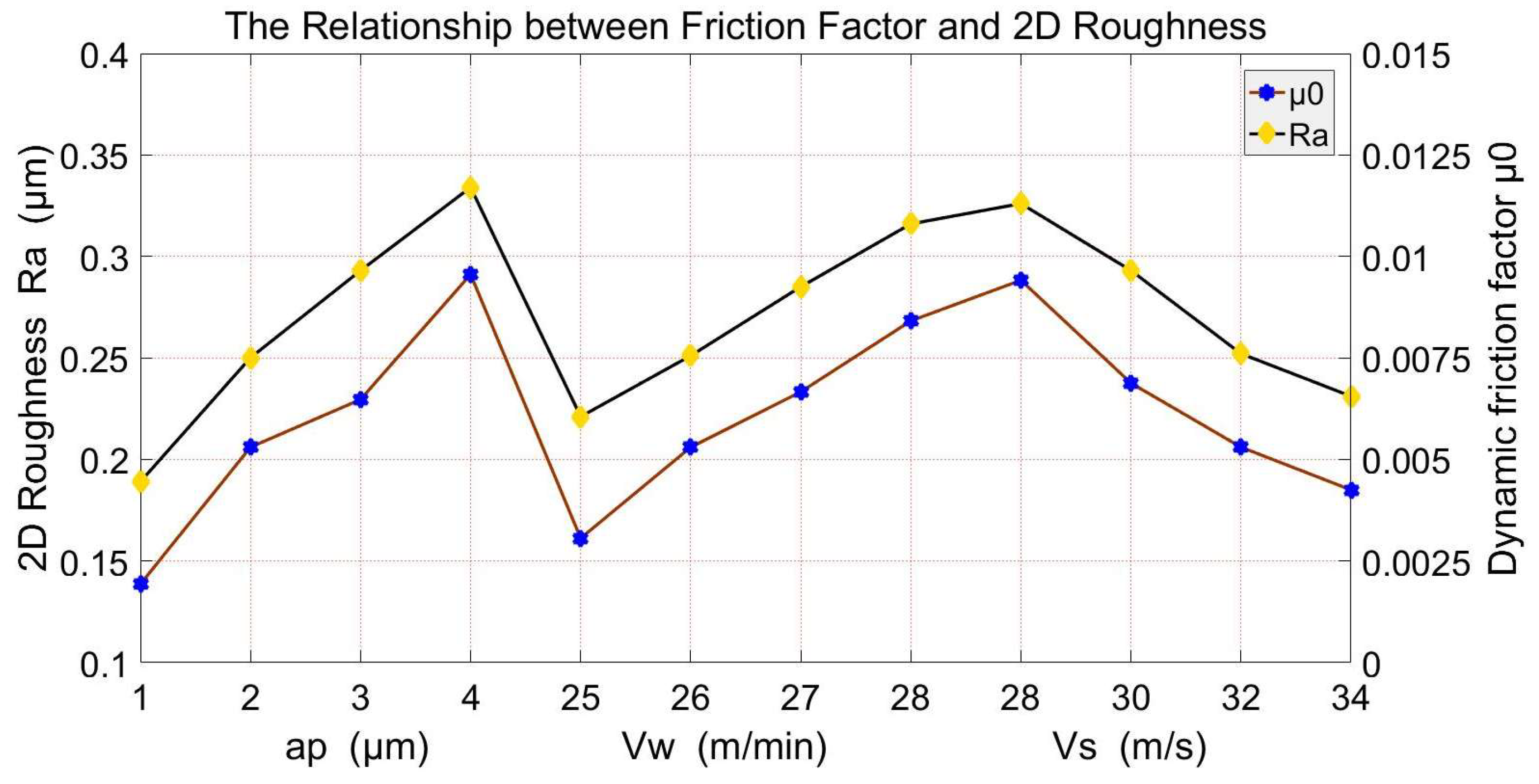
Among them, S1-1, S1-2 and S1-3 are the three same sliders of the S1 group experiment, and the naming method of S1-S10 is consistent. Therefore, a, b and c in Figure 10, Figure 11 and Figure 12 are repeated experiments of the friction force test of guide rail pairs under the same conditions, respectively. The unsteadiness of the movement of a roller in the raceway and the deflector easily has a greater impact on the friction when the speed of the guide rail pair is low. The measured value of friction force in each group of experiments fluctuates in varying degrees within the operating speed range of 1~5 m/min. In order to ensure the accuracy of the friction measurement results, only the statistical analysis on the friction measured within the running in speed of 7~13 m/min is conducted in this paper. The experimental results are shown in Figure 10, Figure 11 and Figure 12, respectively. And the corresponding relationship between the dynamic friction factor and the roughness is shown in Figure 13. It can be seen that the dynamic friction factor μ0 increases with increasing Ra when the grinding depth is in the range of [1, 4 μm] (S1~S3). Within the range of feed speed [25, 28 m/min] (S4~S6), μ0 first decreases and then increases with the Ra, whereas μ0 decreases with the increase of grinding wheel linear speed as the Ra is in a downward trend when the grinding wheel linear speed is in [28, 34 m/min] (S7~S9).
To verify the correctness and effectiveness of the prediction model in Equation (14), the friction force tests are conducted on the roller guide rail precision retention test bench (Figure 3).
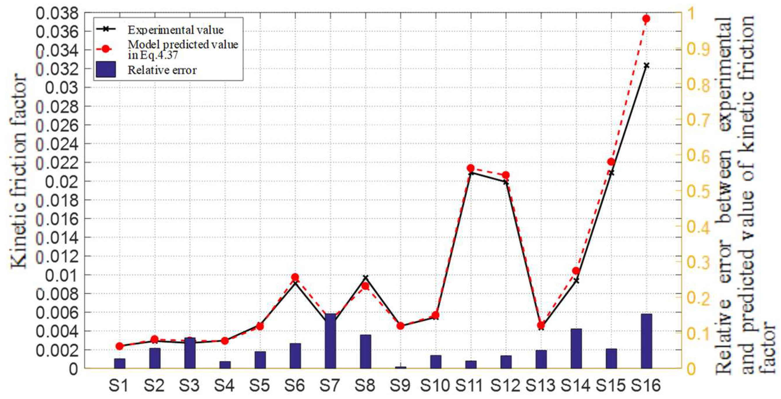
Firstly, the surface of the slider raceway is ground through the three-factor, four-level orthogonal experiment (Table 4), and the geometric characteristics of the surface micro features are extracted from the 3D surface topographies of the slider raceway, as shown in Table 5. The predictive values of the dynamic friction factor are obtained by substituting the average values of groove depth, convex peak and peak–valley structure height of each slider surface in Table 5 into Equation (14). Secondly, the friction force test experiments of guide rail pairs for the sliders obtained from Table 4 are carried out, and the statistical analysis results of the dynamic friction factor are shown in Table 5. The experimental value is compared with the predictive value of dynamic friction factor, and its relative error is calculated. The results are shown in Figure 14.
In Figure 14, it is shown that the experimental values of dynamic friction factors obtained from other groups of experiments are highly consistent with the predicted values except for the 16th group of orthogonal experiments. When the dynamic friction factors are within the range of (0.002 0.0210], the residual error between the experimental values and the predicted values is very small, and the relative error is basically within 10%, whereas when the dynamic friction factor exceeds 0.03, the difference between the experimental value and the predicted value of dynamic friction factor is large, and the experimental value is smaller than the predicted value. And at this time, the surface roughness is higher than 0.7 μm, and the height of surface micro-feature groove and crest exceeds 1 μm.
The reason for this is that for the prediction model, the influence weight of the geometric characteristics of each micro-feature on the dynamic friction factor remains unchanged, which results in that the dynamic friction factor increases with the increase of the surface micro-feature size, and there is no limit on the scope.
However, in the actual process, the experimental value of the dynamic friction factor will change with the changing rate of the surface micro-feature when the surface roughness exceeds a certain range. Therefore, the prediction model of dynamic friction factor has a certain scope of application; that is, the dynamic friction factor is within the range of (0.002 0.0210], or the surface roughness of the slider is not greater than 0.5 μm, or the depth of the surface micro feature groove and the height of the crest shall not exceed 1 μm. For the surface roughness of GZB45BA roller linear guide pair slider, the factory standard of Nanjing Process Equipment Co., Ltd. is not greater than 0.4 μm. Therefore, the simplified prediction model of dynamic friction factor in Equation (14) can be verified to be correct and effective through the orthogonal experiment.
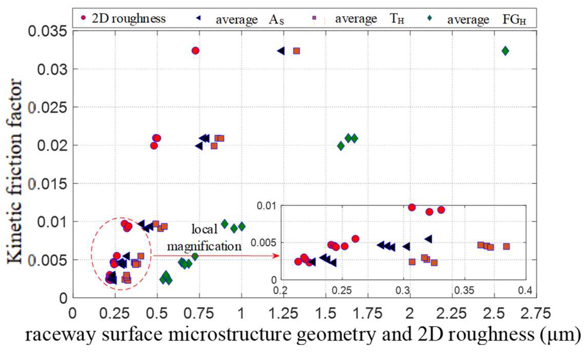
At the same time, it is found from Figure 15 that the dynamic friction factor is not only positively related to the raceway surface roughness but also is increased with the depth of the groove and the height of the peak and the peak–valley. Among them, the height of the convex peak TH has the greatest influence on the dynamic friction factor μ0, followed by the height of the peak–valley structure, while the groove depth has minimal impact. As the micro-geometric features composed of small spacing and valleys on the machined surface of the workpiece are called surface roughness, the size of Ra is determined by the size and distribution of grooves and protrusions. Thus, the rougher the raceway surface is, the more obvious the geometric dimension characteristics of the micro-feature in the surface topography are. And this can be clearly seen from Figure 15. Therefore, the dynamic friction factor increases with the increase of the surface roughness value, which is mainly affected by the groove depth, the height of the peaks and peak–valleys on the surface of the slider raceway. In addition, according to the removal mechanism of the surface material of the slider raceway, the generation of chips and the process of material removal mainly depend on the size of the interaction force between the abrasive particles and the workpiece, the duration of the force and the properties of the surrounding environment (grinding fluid and chips) when the essential characteristics (shape, strength, size, etc.) of the abrasive particles and the properties of the workpiece (hardness, elastic modulus, fracture toughness, etc.) are fixed. The interaction between the abrasive particles and the workpiece is mainly determined by the motion between the grinding wheel and the slider, including the rotational motion of the grinding wheel, radial feed motion and feed motion of the working platform. Therefore, surface roughness is closely related to the linear speed of the grinding wheel, the feed speed of the workpiece and the grinding depth. Therefore, the dynamic friction factor is not only influenced by the geometric characteristics of the surface micro-feature but is also closely related to the friction conditions and workpiece material.

5. Conclusions

The prediction model for the dynamic friction factor of the guide rail pair is established in this paper. It takes into account the influence mechanism of the micro-features of the slider raceway surface with different surface topographies on its dynamic friction factor during the operation of the guide rail pair. According to the removal mechanism of the surface material of the slider raceway, the generation of chips and the process of material removal mainly depend on the size of the interaction force between the abrasive particles and the workpiece, the duration of the force and the properties of the surrounding environment (grinding fluid and chips). However, the interaction between the abrasive particles and the workpiece is mainly determined by the motion between the grinding wheel and the slider, including the rotational motion of the grinding wheel, radial feed motion and feed motion of the working platform. Therefore, the surface of the slider raceway obtained through single factor grinding experiments and orthogonal grinding experiments has different surface topographies. The surface roughness profile extracted from the 3D surface topography of the slider raceway has indicated that Ra increases with increasing grinding depth when the grinding depth is in the range of [1, 4 μm]. Within the range of feed speed [25, 28 m/min], Ra first decreases and then increases with the increase of feed speed, whereas Ra decreases with the increase of grinding wheel linear speed when the grinding wheel linear speed is [28, 34 m/s].
Meanwhile, according to the definition and calculation formula of surface roughness mentioned above, the size of Ra is determined by the size and distribution of grooves and protrusions. When the material and operating conditions of the guide rail are fixed, surface roughness plays a major role in the influencing factors of the dynamic friction factor. From the analysis data of friction testing experiments, it can be seen that the dynamic friction factor not only increases with the increase of the surface roughness value but also is increased with the depth of the groove and the height of the peak and the peak–valley. And the height of the convex peak TH has the greatest influence on the dynamic friction factor μ0, followed by the height of the peak–valley structure, while the groove depth AS minimal impact. In addition, the prediction model of dynamic friction factor has a certain scope of application; that is, the dynamic friction factor is within the range of (0.002 0.0210], or the surface roughness of the slider is not greater than 0.5 μm, or the depth of the surface micro-feature groove and the height of the crest shall not exceed 1 μm.
The dynamic friction factor is not only influenced by the geometric characteristics of the surface micro-feature but is also closely related to the friction conditions and workpiece material. In order to make the application of dynamic friction factor prediction models more widespread, the dynamic friction factor prediction model with different materials and friction conditions will be established in future research.

Author Contributions

Thesis subject and writing, M.K.; Experiments, D.H.; Topography measurement, X.G. All authors have read and agreed to the published version of the manuscript.

Funding

This research was funded by Youth Science and Technology Fund Project 2021QN1019 (January 2021~2023).

Data Availability Statement

Data sharing not applicable.

Conflicts of Interest

The authors declare no conflict of interest.

References

  1. Etsion, I.; Kligerman, Y.; Halperin, G. Analytical and experimental investigation of lase-textured mechanical seal faces. Tribol. Trans. 1999, 42, 511–516. [Google Scholar] [CrossRef]
  2. Etsion, I.; Halperin, G. A laser surface textured hydrostatic mechanical seal. Tribol. Trans. 2002, 45, 430–434. [Google Scholar] [CrossRef]
  3. Etsion, I.; Halperin, G.; Brizmer, V.; Kligerman, Y. Experimental investigation of laser surface textured parallel thrust bearings. Tribol. Lett. 2004, 17, 295–300. [Google Scholar] [CrossRef]
  4. Menezes, P.L.; Kishore; Kailas, S.V. Influence of surface texture on coefficient of friction and transfer layer formation during sliding of pure magnesium pin on 080 M40 (EN8) steel plate. Wear 2006, 261, 578–591. [Google Scholar] [CrossRef]
  5. Kim, B.; Chae, Y.H.; Choi, H.S. Effects of surface texturing on the frictional behavior of cast iron surfaces. Tribol. Int. 2014, 70, 128–135. [Google Scholar] [CrossRef]
  6. Costa, H.L.; Ardila, M.A.N.; Labiapari, W.S.; Silva, W.M.; de Mello, J.D.B. Effect of surface topography on the dynamics of the abrasive particles during micro-abrasion. Wear 2015, 324–325, 129–139. [Google Scholar] [CrossRef]
  7. Wakuda, M.; Yamauchi, Y.; Kanzaki, S.; Yasuda, Y. Effect of surface texturing on friction reduction between ceramic and steel materials under lubricated sliding contact. Wear 2003, 254, 356–363. [Google Scholar] [CrossRef]
  8. Magnus, C.; Gulenc, I.T.; Rainforth, W.M. Ambient dry sliding friction and wear behaviour of laser surface textured (LST) Ti3SiC2 MAX phase composite against hardened steel and alumina. Wear 2022, 490–491, 204184. [Google Scholar] [CrossRef]
  9. Grabon, W.; Pawlus, P.; Wos, S.; Koszela, W.; Wieczorowski, M. Effects of cylinder liner surface topography on friction and wear of liner-ring system at low temperature. Tribol. Int. 2018, 121, 148–160. [Google Scholar] [CrossRef]
  10. Yang, J.; Fu, H.; He, Y.; Gu, Z.; Fu, Y.; Ji, J.; Zhang, Y.; Zhou, Y. Investigation on friction and wear performance of volcano-shaped textured PVD coating. Surf. Coat. Technol. 2022, 431, 128044. [Google Scholar] [CrossRef]
  11. Wang, H.; He, D.; Wu, Y.; Xu, S. Study on wear state evaluation of friction stir welding tools based on image of surface topography. Measurement 2021, 186, 110173. [Google Scholar] [CrossRef]
  12. Pei, X.; Pu, W.; Zhang, Y.; Huang, L. Surface topography and friction coefficient evolution during sliding wear in a mixed lubricated rolling-sliding contact. Tribol. Int. 2019, 137, 303–312. [Google Scholar] [CrossRef]
  13. Zhu, D.; Martini, A.; Wang, W.; Hu, Y.; Lisowsky, B.; Wang, Q.J. Simulation of sliding wear in mixed lubrication. J. Tribol. 2007, 129, 544–552. [Google Scholar] [CrossRef]
  14. Saeidi, F.; Meylan, B.; Hoffmann, P.; Wasmer, K. Effect of surface texturing on cast iron reciprocating against steel under starved lubrication conditions: A parametric study. Wear 2016, 348–349, 17–26. [Google Scholar] [CrossRef] [Green Version]
  15. Yu, H.; Huang, W.; Wang, X. Dimple patterns design for different circumstances. Lubr. Sci. 2013, 25, 67–78. [Google Scholar] [CrossRef]
  16. Braun, D.; Greiner, C.; Schneider, J.; Gumbsch, P. Efficiency of laser surface texturing in the reduction of friction under mixed lubrication. Tribol. Int. 2014, 77, 142–147. [Google Scholar] [CrossRef]
  17. Segu, D.Z.; Kim, S.S. Influence on friction behavior of micro-texturing under lubricated non-conformal contact. Meccanica 2014, 49, 483–492. [Google Scholar] [CrossRef]
  18. Nakano, M.; Korenaga, A.; Korenaga, A.; Miyake, K.; Murakami, T.; Ando, Y.; Usami, H.; Sasaki, S. Applying micro-texture to cast iron surfaces to reduce the friction coefficient under lubricated conditions. Tribol. Lett. 2007, 28, 131–137. [Google Scholar] [CrossRef]
  19. Ren, N.; Nanbu, T.; Yasuda, Y.; Zhu, D.; Wang, Q. Micro textures in concentratedconformal-contact lubrication: Effect of distribution patterns. Tribol. Lett. 2007, 28, 275–285. [Google Scholar] [CrossRef]
  20. Andersson, P.; Koskinen, J.; Varjus, S.E.; Gerbig, Y.; Haefke, H.; Georgiou, S.; Zhmud, B.; Buss, W. Microlubrication effect by laser-textured steel surfaces. Wear 2007, 262, 369–379. [Google Scholar] [CrossRef]
  21. Wang, Z.; He, H.; Wu, S.; Xiang, J.; Ni, J. Effect of surface topography and wettability on friction properties of CFRPEEK. Tribol. Int. 2022, 171, 107573. [Google Scholar] [CrossRef]
  22. Liu, S. Mechanical Performance Analysis of Roller Linear Guide Pair. Ph.D. Dissertation, Huazhong University of Science and Technology, Wuhan, China, 2011. [Google Scholar]
  23. Johson, K.L. Contact Mechanics; Cambridge University Press: Cambridge, UK, 1985. [Google Scholar]
  24. Harris, T.A.; Kotzalas, M.N. Polling Bearing Analysis: First Volume, 5th ed.; Taylor & Francis: Boca Raton, FL, USA, 2007. [Google Scholar]
  25. Kragelsky, I.V.; Dobychin, M.N.; Kombalov, V.S. Friction and Wear: Calculation Methods; Pergamon Press: Oxford, UK, 1982. [Google Scholar]
  26. Oh, K.J.; Khim, G.; Park, C.H.; Chung, S.C. Explicit modeling and investigation of friction forces in linear motion ball guides. Tribol. Int. 2019, 129, 16–28. [Google Scholar] [CrossRef]
  27. Cheng, D.J.; Park, T.J.; Kim, S.J. Improved friction model for the roller LM guide considering mechanics analysis. J. Mech. Sci. Technol. 2018, 32, 2723–2734. [Google Scholar] [CrossRef]
  28. Zhang, W.; Wang, M.; Kong, D. Modeling and experimentation of the friction force of linear rolling guide pair considering oil film resistance. Chin. J. Eng. 2017, 39, 1718–1726. (In Chinese) [Google Scholar]
  29. Wang, Y.; Zu, L.; Ou, Y.; Feng, H. Relationship between frictional force and preload of linear rolling guide. Modul. Mach. Tool Autom. Manuf. Tech. 2018, 6, 12–14. (In Chinese) [Google Scholar]
  30. Ge, S.; Zhu, H. Fractals in Tribology; Mechanical Industry Press: Shanghai, China, 2005. [Google Scholar]
  31. Norden, B.N. On the Compression of a Cylinder in Contact with a Plane Surface; National Institute of Standards and Technology: Gaithersburg, MD, USA, 1973. [Google Scholar]
  32. Hu, Y.; Gan, Z. Tolerance Fit and Measurement—Practical Planning Textbook for Vocational and Technical Colleges in the New Century; Tsinghua University Press: Beijing, China, 2005. [Google Scholar]
  33. Liu, J. Theory and Experiment of Rolling Linear Guideway. Ph.D. Dissertation, Huazhong University of Science and Technology, Wuhan, China, 1985. [Google Scholar]
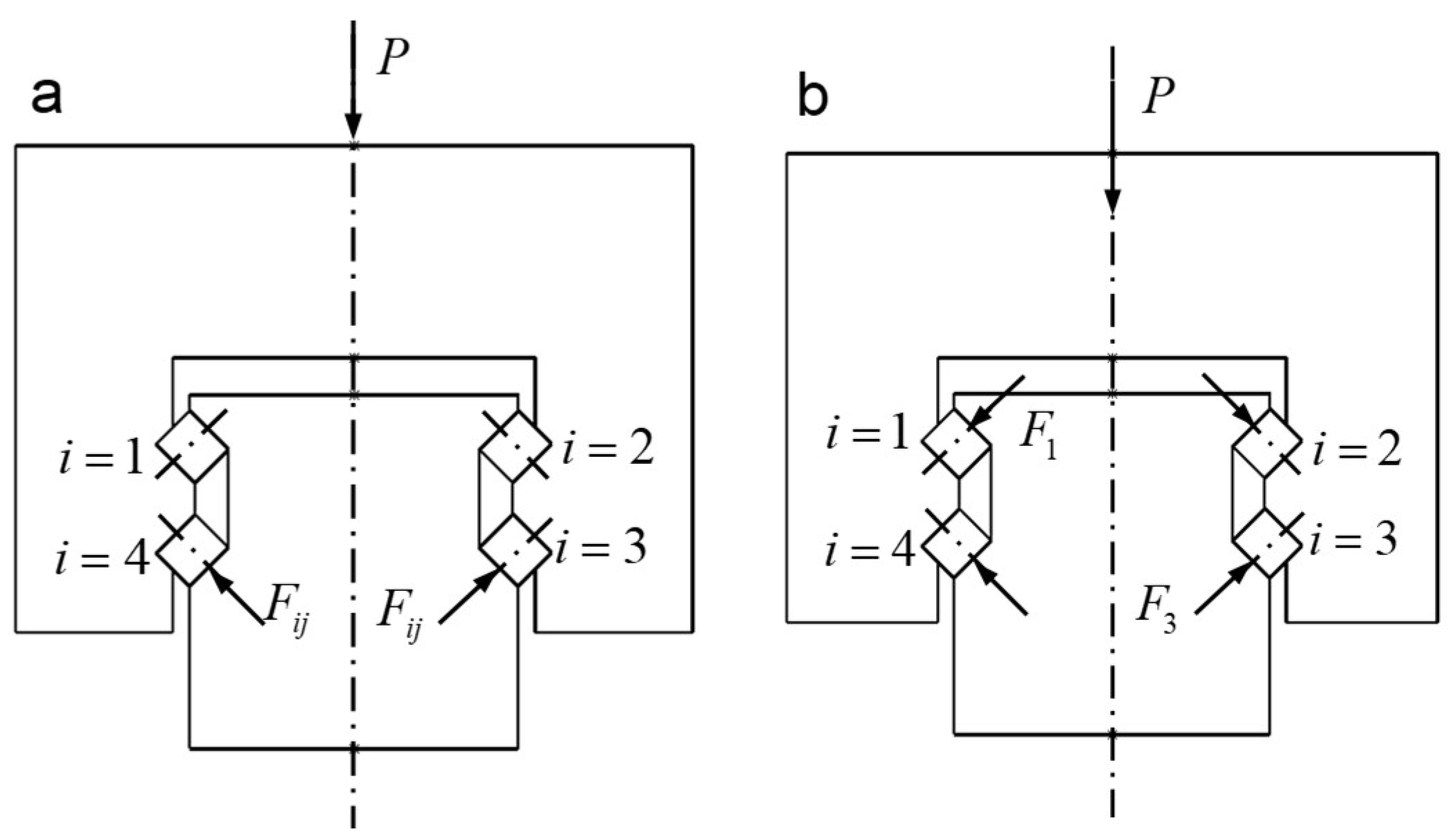
Figure 1. A simplified force model of the single guide rail pair with a single slider: (a) Without preload; (b) With preload.
Lubricants 11 00321 g001
Figure 2. Schematic diagram of roller deformation.
Lubricants 11 00321 g002
Figure 3. Friction of sliders with different surface roughness under the same load.
Lubricants 11 00321 g003
Figure 4. Dimensional characteristics of grooves and convex peaks in surface micro-features.
Lubricants 11 00321 g004
Figure 5. The average value of the 2D roughness of the slider S10 obtained from experimental measurements.
Lubricants 11 00321 g005
Figure 6. Dimension of roller linear guide pair and type of slider width.
Lubricants 11 00321 g006
Figure 7. Rolling guide sub-precision retention test bench.
Lubricants 11 00321 g007
Figure 8. Schematic diagram of the tribological test principle of the guide rail pair.
Lubricants 11 00321 g008
Figure 9. The 3D surface topography of the slider raceway: (ad) Vw = 25 m/min and Vs = 32 m/s; (eh) Vw = 25 m/min and ap = 2 μm; (il) Vs = 32 m/s and ap = 2 μm.
Lubricants 11 00321 g009
Figure 10. Friction force test results of three sets of guide rail pairs assembled by sliders obtained from different grinding depths: (ac) are repeated experiments of the friction force test of guide rail pairs under the same conditions, respectively.
Lubricants 11 00321 g010
Figure 11. Friction force test results of three sets of guide rail pairs assembled by sliders obtained from different feeding speeds: (ac) are repeated experiments of the friction force test of guide rail pairs under the same conditions, respectively.
Lubricants 11 00321 g011
Figure 12. Friction force test results of three sets of guide rail pair assembled by sliders obtained from different linear speeds: (ac) are repeated experiments of the friction force test of guide rail pairs under the same conditions, respectively.
Lubricants 11 00321 g012
Figure 13. The relationship between the dynamic friction factor and the 2D roughness.
Lubricants 11 00321 g013
Figure 14. Comparison between the experimental and predicted values of the dynamic friction factor obtained from the orthogonal test.
Lubricants 11 00321 g014
Figure 15. Influence of the micro-feature and 2D roughness of the slider raceway on the dynamic friction factor.
Lubricants 11 00321 g015
Table 1. The 2D roughness, surface micro-feature geometry characteristics and dynamic friction factor of slider S1 to S10 with different grinding process parameters.
SliderRa [μm]ASAWASWTHTWTHWFGHFGWTest
Value μ0
Predictive
Value μ0
Residual
S10.1890.2140.2952.7400.2950.2951.4440.5090.5890.0019320.0019102.1652 × 10−5
S100.2500.2960.2943.5780.3770.2941.8480.6720.5880.0052990.0048814.1800 × 10−4
S20.2930.3770.2944.3120.4580.2942.2450.8350.5870.0064720.006594−1.2180 × 10⁻⁴
S30.3340.4600.2935.1190.5410.2932.6571.0020.5860.0095540.0094321.2180 × 10−4
S40.2210.2390.2952.9520.3190.2941.5640.5590.5890.0030600.003162−1.0216 × 10⁻⁴
S100.2510.2960.2953.5960.3770.2941.8440.6730.5890.0052990.0052376.1534 × 10−5
S50.2850.3520.2944.0830.4340.2942.1190.7860.5880.0066590.006749−8.9743 × 10⁻⁵
S60.3160.4080.2934.6370.4910.2942.4010.8990.5870.0084090.0082751.3363 × 10−4
S70.3260.4360.2934.8800.5200.2942.5410.9550.5870.0094100.009427−1.6539 × 10⁻⁵
S80.2930.3660.2944.2690.4480.2942.1880.8150.5880.0068750.007105−2.3007 × 10⁻⁴
S100.2520.2960.2953.5700.3770.2951.8420.6730.5890.0052990.0046746.2500 × 10−4
S90.2310.2600.2943.2050.3410.2931.6670.6010.5880.0042480.0040901.5772 × 10−4
Table 2. Dimension of roller heavy-duty linear guide pair GZB45BA (mm).
HW1SliderKWTH1Slider LengthRaceway Length BEMax. Length of Single PieceRated Dynamic Load (kN)
guide rail pair7020.5 6286158153106guide rail4538600092.6
Table 3. Specific grinding process parameters, experimental samples and devices.
No.Vw [m/min]Vs [m/s]ap [μm]Experimental Samples and Devices
S125321Grinding workpieceGZB45BA
S225323
S325324Workpiece materialGCr15
S425282Wheel type1A46X25X13-SA100K35
S525302Wheel materialalumina
S625342GrinderPLANMATHP408
S726322Grinding fluidFully synthetic water-soluble cutting fluid
S827322
S928322
S1025322
Table 4. Orthogonal experimental design table for grinding of sliders with different surface topographies.
Number of TrialsAp [μm]Vw [m/min]Vs [m/s]Number of Sliders
1225283
2228303
3231323
4234343
5325303
6328283
7331343
8334323
9425323
10428343
11431283
12434303
13525343
14528323
15531303
16534283
Table 5. Comparison of the experimental value of the dynamic friction factor with the predicted value obtained by the simplified model of Equation (14).
SliderRa [μm]ASAWTHTWFGHFGWExperimental
Value μ0
Predictive
Value μ0
ResidualRelative Error
S10.21420.2260.2940.3070.2940.5340.5880.0024080.0023436.53 × 10−50.0271
S20.22320.2430.2930.3250.2930.5680.5860.0029270.003092−1.65 × 10−40.0564
S30.22000.2380.2940.3190.2940.5560.5880.0027180.002952−2.33 × 10−40.0859
S40.21890.2350.2940.3170.2940.5510.5880.0029780.0029215.74 × 10−50.0193
S50.24110.2820.2950.3630.2940.6440.5890.0046680.0044482.21 × 10−40.0472
S60.32130.4360.2930.5190.2940.9550.5870.0090870.009725−6.38 × 10−40.0702
S70.25210.3030.2930.3840.2940.6860.5870.0044730.005162−6.89 × 10−40.1539
S80.30700.4080.2940.4910.2940.8990.5890.0096850.0087739.12 × 10−40.0941
S90.24370.2870.2940.3680.2940.6550.5880.0045370.0045171.99 × 10−50.0044
S100.26090.3210.2940.4020.2940.7230.5880.0054730.005673−2.00 × 10−40.0366
S110.49300.7740.2940.8590.2941.6330.5880.0209160.021360−4.44 × 10−40.0212
S120.48160.7520.2930.8370.2931.5890.5860.0199040.020612−7.08 × 10−40.0356
S130.24500.2910.2940.3710.2940.6620.5880.0043600.004582−2.22 × 10−40.0509
S140.33090.4600.2940.5410.2941.0010.5870.0093570.010399−1.04 × 10−30.1114
S150.50060.7930.2930.8770.2941.6690.5870.0208890.022035−1.15 × 10−30.0549
S160.72761.2390.2941.3260.2942.5650.5880.0323620.037312−4.95 × 10−30.1530
Disclaimer/Publisher’s Note: The statements, opinions and data contained in all publications are solely those of the individual author(s) and contributor(s) and not of MDPI and/or the editor(s). MDPI and/or the editor(s) disclaim responsibility for any injury to people or property resulting from any ideas, methods, instructions or products referred to in the content.