Abstract
Cu-based self-lubricating materials can effectively adapt to complex natural environments and ensure consistency in materials used for switch transitions. These materials were tested through interface reinforcement research, improving their mechanical and tribological properties and providing a theoretical basis for new switch slide baseplate materials. Results showed that the coefficient of friction and wear weight loss of Cu-based self-lubricating materials decreased with an increase in graphite content after Cu and Ni plating on the graphite surface, reaching a minimum value at a graphite content of 6 wt.%. The coefficient of friction and wear weight loss of the Ni-plated material were reduced 11.1% and 85.6%, respectively, whereas the coefficient of friction and wear weight loss of Cu-plated materials were reduced 7.2% and 78.4%, respectively. Compared to Cu plating, Ni plating substantially enhanced the friction and wear performance of Cu-based self-lubricating materials. Cu and Ni plating increased the adhesion of the materials on the pin surface and the adhesive materials’ composition was consistent with the lubricating film, which changed the grinding mechanism between the pin and the disk. Ni plating had a stronger effect on the tribological performance of Cu-based self-lubricating materials than Cu plating.
1. Introduction
Switch slide baseplates (SSBs) play a crucial role in railway tracks, providing reliable service to ensure safe railway operations. As the high-speed railway age dawns, there is an urgent need for the development of a new generation of SSBs with self-lubricating capabilities [1,2,3]. Due to the superior self-lubricating properties and corrosion resistance of Cu-based self-lubricating materials, they can effectively adapt to complex natural environments and ensure consistency in the materials used for switch transitions [4,5,6,7].
Previous studies indicate that Cu-based self-lubricating materials have good anti-wear properties when the graphite content is less than 4 wt.% [8,9,10]. However, when the graphite content exceeds 4 wt.%, the tribological properties decrease with increasing graphite content. The main reason is that the bonding strength of carbon and Cu is low, the graphite itself and the Cu are not wetted at all, the wetting angle between graphite and Cu can reach 140° at 1100 °C, and graphite and copper do not react, so that the bonding mode of carbon and Cu is mechanical [11,12]. There are many pores at the interface between graphite and Cu. With an increase in graphite content, the interface between the graphite and Cu increases and the number of pores increases as well [13]. When the graphite content is too high, the graphite forms a network structure and breaks the matrix, resulting in a sharp decline in the relative density, hardness, and flexural strength of the materials. In the wear process, the graphite substrate is spalled off, which increases the surface roughness of the materials, increases the coefficient of friction, and makes the friction and wear performance of Cu-based self-lubricating materials deteriorate [14,15,16].
Adjusting the interfacial state of graphite and Cu can effectively enhance the interfacial bonding strength and flexural strength of the materials [17,18,19,20,21,22]. The commonly used additives for tribology such as graphene and MXene show better performance [23]. The interface design is the most critical aspect of preparing Cu-based self-lubricating materials, as it significantly impacts their properties, and its investigation will be this paper’s primary focus. Engineering research has employed interfacial modification and strengthening techniques with traditional materials to enable the use of such materials in emerging fields [24,25]. This study’s Cu-based self-lubricating materials may be utilized for interface reinforcement and so are suitable for switch slide baseplates in various working conditions.
Cu and Ni are elements that do not react with graphite (carbon) and are infinitely solvable or highly solvable with copper. This kind of metal element does not produce new phases in the preparation of Cu-based self-lubricating materials; the instability factor is thus reduced in this test, which is more conducive to comparing the ability of different plated metals to regulate the interface [26,27,28].
This study employs Cu and Ni surface plating on graphite powder to control the interface of Cu-based self-lubricating materials, improve its mechanical and tribological properties, and provide a theoretical basis for new SSB materials. Although Cu and Ni have matured electroless plating processes, their application to graphite powder has not been widely used, making them a valuable area of research.
2. Materials and Methods
2.1. Materials
This study utilized flake graphite’s superior lubrication properties as the raw material for Cu-based self-lubricating materials. The flake graphite powder used in this study had a particle size of 45 μm and a purity level exceeding 98.5%. The microstructure of the raw particles, as shown in Figure 1, was analysed and observed utilizing a scanning electron microscope (SEM). Transmission electron microscope (TEM) analysis indicated a densely packed hexagonal (002) direction in the graphite’s layered structure. This study employed 99.9% pure copper and nickel powder, which were water-atomized commercial powders with a particle size of 400 μm. The first four treatments of the graphite surface are collectively known as graphite surface pre-treatment. Electroless Cu and Ni plating require pre-treatment, and the process is identical. Therefore, the graphite used in both plating methods simultaneously underwent pre-treatment. The specific steps entailed cleaning the graphite powder with a 20 wt.% NaOH solution. The cleaned graphite powder was then mixed with a sensitized solution (15 mL/L HCl and 10 g/L SnCl), and stirred for 15 min. Subsequently, the sensitized graphite powder was added to an activation solution (15 mL/L HCl and 0.3 g/L PdCl2) and stirred for 15 min. The surface-activated graphite powder was then treated with a reduction solution (40 wt.% NaH2PO2·H2O) by stirring for 15 min. The graphite powder was then added to the plating solution once the process was complete.
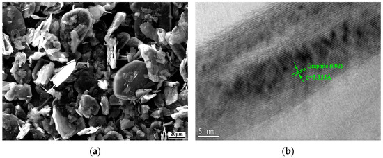
Figure 1.
SEM and TEM images of the raw graphite. (a) SEM image; (b) TEM image.
Table 1 displays the composition of the Cu-based self-lubricating materials, with Ni accounting for 8 wt.%, graphite ranging from 1 wt.%~6 wt.%, and Cu constituting the remainder. For clarity, this study assigned numbered labels to the Cu-based self-lubricating materials prepared with non-plated graphite, Cu-plated graphite, and Ni-plated graphite based on different graphite contents, as displayed in Table 1. C1~C6 indicates the Cu-based self-lubricating materials prepared with Cu-plated graphite ranging from 1 wt.%~6 wt.% content, while N1~N6 denotes the Cu-based self-lubricating materials prepared with Ni-plated graphite ranging from 1 wt.%~6 wt.% content. The Cu-based self-lubricating materials were produced utilizing the powder metallurgy method, comprising five steps: ball milling, compact pressing, sintering, repressing, and re-sintering.

Table 1.
Chemical composition of Cu-based self-lubricating materials.
2.2. Wear Test
The Cu-based self-lubricating materials used in this test worked as an SSB in a switch system with the point rail as the friction pair. The grinding material utilized was U75V point rail steel, whose properties are listed in Table 2.

Table 2.
Mechanical properties of U75V point rail steel.
Figure 2a shows the point rail used as the pin sample, and its SEM morphology is shown in Figure 2b. To properly design the wear test, The test employed MMW-1 and the computed test parameters were based on the SSB’s practical performance under low-speed and high-load conditions. The pin sample was first processed into a 5 mm × 5 mm × 12 mm cuboid, with one point polished into a circular contact surface with a chamfered diameter of 2.5 mm. The disk sample was prepared as a cylindrical sample with a thickness of 5 mm and a radius of 22 mm. For this test, the loading direction was from bottom to top, with the centre of the disk sample serving as the loading position. The pin sample served as the rotating sample, while the disk sample was fixed. The conversion force of the switch rail was 10 kN, with an actual contact area of 0.1 m × 0.13 m between the rail and SSB and an estimated test load of 20 N for the actual contact area of π × 1.25 mm × 1.25 mm between the pin and the disc. The switch conversion rate was 0.065 m/s, with a wear testing machine wear radius of 12.5 mm, resulting in a friction rate of 50 rpm. Based on the actual cleaning cycle of the switch and calculations of the number of cycles in a switch, the grinding process was estimated to be about 100 m. Hence, grinding was carried out for a distance of 100 m, and the calculated wear time was determined to be 1530 s based on the grinding process and friction rate. As the SSB represents the working condition of the point rail, the wear mode of the upper pin was adopted for this test; the pin sample was U75V and the disc sample was composed of Cu-based self-lubricating material.
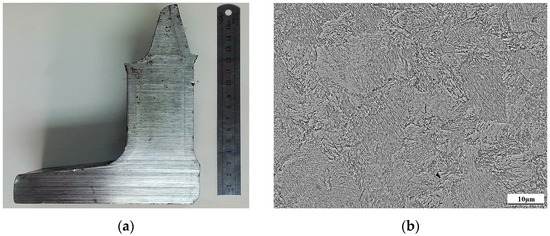
Figure 2.
Point rail and wear test machine. (a) Point rail image; (b) Microstructure of point rail.
The disk mass was measured as m0 before the test and m1 after the test. The test had a grinding distance of 100 m and a wear area of π × 1.25 mm × 1.25 mm. Equation (1) displays the calculation formula of the wear weight loss. Each component sample underwent 8 tests, and the average value was determined.
where m0—mass/g of test front disk sample; m1—mass/g of the test disc sample after the test; L—grinding distance/m; and S—wear area/m2.
3. Results
3.1. Microstructure and Mechanical Properties
The graphite that underwent electroless Ni/Cu plating was utilized to produce Cu-based self-lubricating materials. The microstructure demonstrated a distribution of two phases, the matrix α phase and the graphite phase. Previous reports [17,18] indicate that Ni and Cu plating on the graphite powder surface can considerably improve the interfacial bonding between the graphite and matrix and will overcome the issue of their low bonding strength. The relative density, hardness, and flexural strength of Cu-based self-lubricating materials were measured. This study showed a significant improvement in the mechanical properties of the material when Cu and Ni were plated on the graphite surface. This improvement was due to the plating enhancing the interface bonding strength between the carbon and Cu in the materials. As a result, the relative density, hardness, and flexural strength of the materials were also significantly improved. The specific results of the performance evaluations are presented in Table 3.

Table 3.
Mechanical properties of Cu-based self-lubricating materials.
3.2. Tribological Properties
The coefficient of friction for each test was obtained by recording the coefficient of friction of the wear testing machine at 30 ms intervals and calculating the average value. In order to enhance the reliability of the test, the experiment was repeated 8 times for each group of samples. Figure 3 displays the test results. The figure indicates that the coefficient of friction of the Cu-based self-lubricating materials prepared by Cu and Ni plating on the graphite powder surface gradually decreases with the increase in the graphite content. The material containing 6 wt.% graphite content demonstrated the lowest coefficient of friction. The minimum coefficient of friction of the Cu-plated material was 0.142, while that of the Ni-plated material was 0.136. The coefficient of friction of Ni- or Cu-plated materials were reduced 11.1% and 7.2%, respectively. Compared with the materials lacking graphite powder, the coefficient of friction of the materials slowly increased when the graphite content exceeded 4 wt.%. Graphite forms a network structure that splits the matrix, and the matrix spalling off in the wear process causes an increase in the coefficient of friction. The bonding strength between carbon and Cu improves after Cu and Ni plating on the graphite powder surface. When the graphite content exceeds 4 wt.%, the bonding strength of the graphite and matrix strengthens. As a result, spalling of the material’s matrix does not occur. When subjected to the same graphite content, the coefficient of friction of the materials prepared by Cu- and Ni-plating graphite powders were compared, and the Ni-plated materials demonstrated a lower coefficient of friction than the Cu-plated materials.
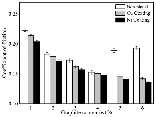
Figure 3.
Coefficient of friction with different plating conditions and different graphite content.
Figure 4 reveals that the wear weight loss of Cu- and Ni-plated graphite materials decreased as the graphite content increased, reaching its lowest point with 6 wt.% graphite content. The Cu-plated and Ni-plated materials’ minimum wear weight losses were found to be 0.611 g·m−3 and 0.407 g·m−3, respectively. The wear weight loss of non-plated materials reached 4.088 g·m−3 at 6 wt.% graphite content, surpassing that of materials prepared with Cu- and Ni-plated graphite. The wear weight loss of Ni- or Cu-plated material was reduced 85.6% and 78.4%, respectively. Cu and Ni plating on the graphite surface resulted in a noticeable enhancement of the bonding strength between graphite and matrix. Material interfacial bonding became stronger when the graphite content surpassed 4 wt.%, eliminating any mass-spalling phenomena and reducing wear weight loss remarkably. When composed of equal graphite content, the Ni-plated material exhibited lower wear weight loss than the Cu-plated material. Hence, Ni plating demonstrated better friction and wear performance improvement than Cu plating.
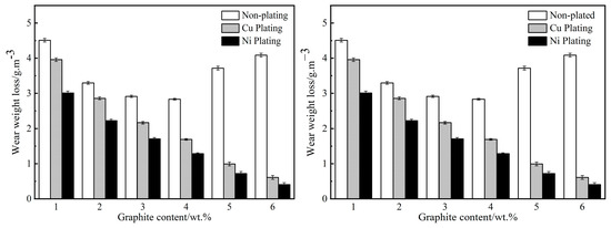
Figure 4.
Wear weight loss with different plating conditions and different graphite content.
3.3. XPS Results of Worn Surfaces
XPS analysis was carried out on the wear surface of disk samples O6, C6, and N6 to determine the chemical forms of the elements present. Figure 5 shows the XPS analysis results of the wear surface of the O6 sample, where the existence of C in graphite form is evident. The analysis in Figure 5a indicates that the existing chemical forms of Cu elements on the worn surface are Cu and CuO. Similarly, the analysis in Figure 5b shows that the existing chemical forms of Fe elements are Fe and Fe2O3. Furthermore, the analysis in Figure 5c reveals that the existing chemical form of Ni is NiO. According to the analysis in Figure 5d, the chemical forms of element O are CuO, Fe2O3, and NiO. Therefore, the friction surface of O6 is composed of C, Cu, CuO, Fe, Fe2O3, and NiO.
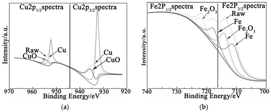
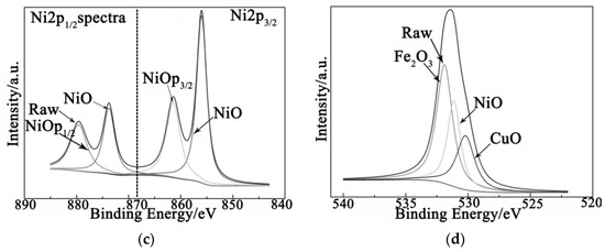
Figure 5.
XPS results of O6 sample. (a) Cu element; (b) Fe element; (c) Ni element; (d) O element.
Figure 6 shows the XPS analysis results of the wear surface of the C6 disk sample, where the chemical forms of Cu are Cu, Cu2O, and CuO; Fe are Fe and Fe2O3; Ni is NiO; and O are CuO, FeO, and NiO. Therefore, the wear surface of the C6 disk sample is composed of C, Cu, Cu2O, CuO, Fe, Fe2O3, and NiO.
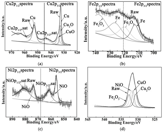
Figure 6.
XPS results of C6 sample. (a) Cu element; (b) Fe element; (c) Ni element; (d) O element.
The XPS results of the wear surface of the N6 disk are shown in Figure 7, indicating the chemical forms of Cu as Cu, Cu2O, and CuO; Fe as Fe, Fe2O3, and FeO; Ni as NiO; and O as CuO, FeO, and NiO. Therefore, the friction surface of N6 is composed of C, Cu, Cu2O, CuO, Fe, Fe2O3, FeO, and NiO.
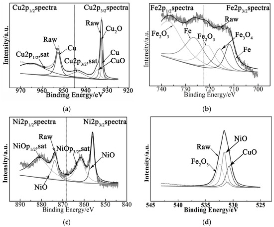
Figure 7.
XPS results of N6 sample. (a) Cu element; (b) Fe element; (c) Ni element; (d) O element.
On the wear surface of the O6, C6, and N6 disks, elements were compared to determine the effects of Cu and Ni plating on the graphite surface. This comparison of the forms of presence on the wear surface showed that the Cu and Ni plating resulted in the production of oxidation intermediates, specifically Cu2O and Fe3O4. This finding indicates that oxidation wear failure is more severe in Cu-based self-lubricating materials that have undergone Cu and Ni plating on graphite surfaces rather than non-plated samples.
4. Discussion
The wear weight loss and friction coefficient of Cu-based self-lubricating materials, prepared by Ni-plating and Cu-plating graphite powder, differ markedly from those of the non-plated material. Figure 8 shows a comparison of the wear surface of disk samples with different graphite content. The wear surface of the O2 disk sample exhibits numerous furrows, with no tissue spalling visible (Figure 8a). Conversely, the wear surface of the C2 and N2 disk samples display numerous furrows, with slight fatigue wear failures apparent (Figure 8a,e). By contrast, when the graphite content was 2 wt.%, the wear surface morphology of the disk sample was little different before and after plating. Consequently, placing graphite powder on this surface does not highlight the advantages of the plating process effectively. As can be seen from Figure 8b, the furrow on the wear surface of the O4 disk specimen decreased, and the fatigue wear failure intensified. Similarly, Figure 8d indicates the furrow on the wear surface of the C4 specimen decreased and the fatigue wear failure intensified. In contrast, Figure 8f illustrates that the furrow depth on the wear surface of the N4 specimen decreased markedly, and the fatigue wear failure slowed down. Upon comparing the wear surfaces of the three disk samples, the failure modes of the wear surfaces are similar, and the difference in the wear surface ratios is not obvious. Therefore, they do not effectively reflect the improvement effect of the graphite surface plating on the tribological properties of the Cu-based self-lubricating materials.
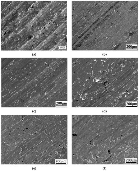
Figure 8.
SEM analysis of worn surfaces. (a) O2 sample; (b) O4 sample; (c) C2 sample; (d) C4 sample; (e) N2 sample; (f) N4 sample.
The wear surface morphology of the O6, C6, and N6 disk samples was analysed using SEM, as shown in Figure 9. Figure 9a displays the wear surface morphology of the O6 disk samples, revealing numerous spalling pits on the surface. This is due to the graphite forming a cutting network that causes the matrix to spall. As a result, the lubrication film is unable to cover the wear surface effectively. Figure 9c shows the wear surface morphology of the C6 disk samples. The analysis revealed no visible spalling pits on the surface, and the surface is complete. However, the fatigue failure is severe. Therefore, Cu plating on the graphite surface reduces the coefficient of friction and wear weight loss of the materials to a certain extent. Figure 9e illustrates the wear surface morphology of the N6 disk samples. The analysis shows that the surface is fairly complete, with less fatigue failure and no spalling pits. Thus, the coefficient of friction and wear weight loss of N6 were the lowest, demonstrating that Ni-plated graphite improves the friction and wear performance of the materials compared to the Cu-plated samples. The surfaces of the disk samples labelled O6, C6, and N6 were analysed through 3D laser topography to assess their wear and roughness. The outcome of this analysis is illustrated in Figure 9b,d,f. The wear surface of disk sample O6 has several spalling pits, which resulted in a roughness of the wear surface of roughly 4.45 μm; this roughness was responsible for an increase in the coefficient of friction of the O6 disk. In comparison, through the 3D laser morphology of the wear surface of disk C6 in Figure 9d, we can conclude that the wear surface of disk C6 is flat, with shallow furrows and a roughness of roughly 1.5 μm, leading to a lower coefficient of friction than that of disk O6. The 3D laser morphology of the wear surface of disk N6 in Figure 9f shows that the wear surface is flat, has slight micro-cutting, and has a roughness of about 1.01 μm. Therefore, the coefficient of friction of N6 is the lowest. This analysis demonstrates that the Ni and Cu plating on the graphite powder surface can effectively reduce the roughness of the wear surface, and that the effect of Ni plating is better than Cu plating.
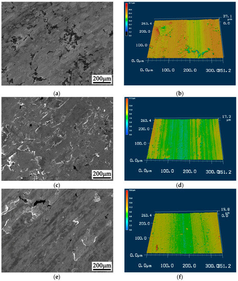
Figure 9.
SEM and 3D laser analysis of worn surfaces. (a) O6 SEM image; (b) O6 3D laser morphology; (c) C6 SEM image; (d) C6 3D laser morphology; (e) N6 SEM image; (f) N6 3D laser morphology.
The surface of the pin sample that was ground using the O6 disk sample underwent both SEM and EDS analysis, with the results presented in Figure 10. The figure shows adhesion of the wear surface of the O6 pin specimen to both the matrix and graphite of the disc specimen. Additionally, it was observed that mass transfer occurred between the matrix and graphite during the wear test. Notably, the amount of graphite mass transfer was limited, and the area covered on the wear surface of the pin was small. Further, the mass transfer of the matrix was significantly greater than that of graphite, indicating that the adhesion of the matrix is better than that of graphite. The analysis in Figure 10 reveals that the area of overlap between the graphite mass transfer region and the matrix mass transfer region is small. The low bonding strength between the graphite and the matrix interface results in the separation of mass transfer between the two materials during the grinding process of the disk sample and the pin sample, which is why the mass transfer areas do not coincide. Additionally, the disk wear surface’s abundant matrix spalling results in a considerable amount of exposed graphite. In turn, this leads to insufficient coverage of the bare matrix and graphite by the lubrication film that forms on the disk surface. Thus, the matrix and graphite mass transfers do not occur in the same area. Consequently, the wear pairing between the pin and disk leaves behind U75V anti-grinding Cu-based self-lubricating material, which explains the high coefficient of friction and wear rate of the O6 sample.
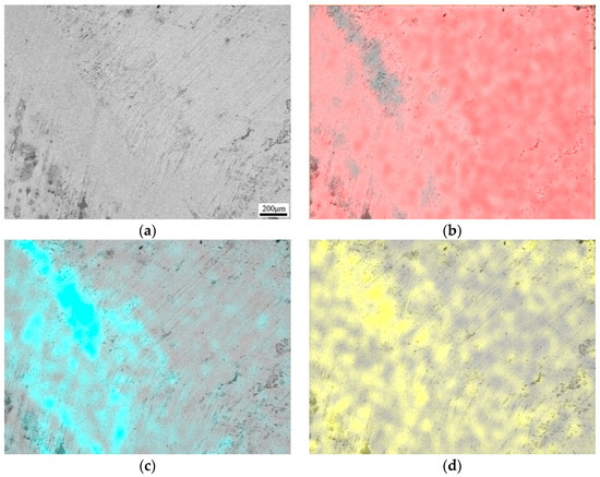
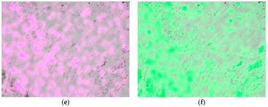
Figure 10.
SEM and EDS analysis of O6 pins. (a) SEM image; (b) EDS mapping of Fe element; (c) Cu element; (d) C element; (e) Ni element; (f) O element.
SEM morphology and EDS analysis were performed on the surface of the C6 disk specimen, with the results shown in Figure 11. The figure indicates that mass transfer occurs between the matrix and graphite during the grinding of both the pin sample and disk sample. The graphite adheres to the wear surface of the pin sample, and the adhesive material of the C6 disk sample on the pin surface adhered along the wear direction. Further, the adhesive area covered by graphite on the wear surface of the pin sample was larger than that on the O6 pin sample. The adhesive region of the C6 pin specimen surface’s matrix coincides with the graphite adhesive area. Additionally, the high oxygen content region coincides with the adhesive area, which indicates that the lubricating film formed on the C6 disk specimen’s wear surface covered the adhesive on the pin surface. That is, during the grinding process, the pin specimen and C6 disk specimen adhered to the lubricating film formed on the wear surface of the C6 disk specimen. This change from U75V to the lubrication film reduced the coefficient of friction and wear rate of the C6 disk sample compared to that of the O6 sample.
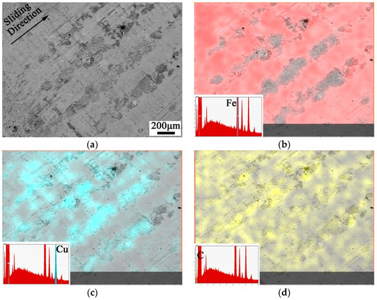
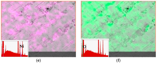
Figure 11.
SEM and EDS analysis of C6 pins. (a) SEM image; (b) EDS mapping of Fe element; (c) Cu element; (d) C element; (e) Ni element; (f) O element.
Figure 12 presents both the surface SEM morphology and EDS analysis results of the N6 disk sample and grinding pin sample. The figure indicates that mass transfer occurs between the matrix and graphite during the pin-on-disk grinding process, with the graphite adhering to the pin sample. The expansion direction of N6 adhesion aligns with the wear direction, and the graphite adhesive region covers a larger wear surface area than the C6 and O6 pin surfaces. The adhesive regions of the N6 pin samples indicate that the matrix adhesive region coincides with the graphite adhesive region, with the high oxygen content area matching the adhesive area. This is a sign that the lubricating film on the wear surface of the N6 disk specimen covered the adhesive on the pin surface. As a result, the anti-wear pair changed from the U75V anti-wear lubricating film to an anti-wear lubricating film. The fatigue failure of the wear surface of the N6 disk samples was consequently less, and the coefficient of friction and wear rate of the N6 disk samples were lower than those of the C6 disk samples. Furthermore, the effect of Ni plating on Cu-based self-lubricating materials for improving wear performance was greater than that of Cu plating.
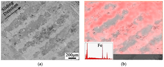
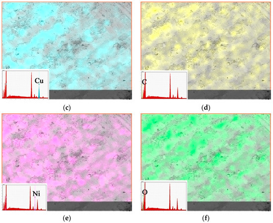
Figure 12.
SEM and EDS analysis of N6 pins. (a) SEM image; (b) EDS mapping of Fe element; (c) Cu element; (d) C element; (e) Ni element; (f) O element.
The wear surfaces of samples O6, C6, and N6 were analysed through direct section SEM analysis, and the results are shown in Figure 13. The analysis revealed numerous spalling pits on the subsurface of O6, thereby indicating that the matrix has a low bonding strength with graphite, leading to a considerable amount of matrix spalling during the wear process. Direct section plane analysis of C6 in Figure 13c shows that the wear surface is flat. The analysis reveals that the matrix that appears to be spalling in the area of weak diffusion bonding between graphite and matrix or in the area of mechanical bonding was cleaved by graphite and exposed on the wear surface. Figure 13e shows the straight section of N6, on which there are no spalling pits formed by tissue spalling on the subsurface, and the wear surface is flat. Consequently, the wear rate on the graphite powder surface of the Cu-based self-lubricating materials after Ni plating is lower than that on the surface of the graphite powder with Cu plating and without Ni plating. Oblique section analysis was also conducted. SEM analysis was carried out on the oblique section of samples O6, C6, and N6, and the results of the analysis are depicted in Figure 13b,d,f. According to the analysis in Figure 13b, the whole matrix wrapped by graphite appears to have spalling on the subsurface of O6. The bonding strength of carbon and Cu is low, and the matrix spalling during the wear process led to an increase in the wear rate of O6. Figure 13d shows that in the subsurface layer of C6’s wear surface, the matrix is well combined with graphite, the matrix completely plated with graphite does not flake off, and there are spalling pits formed by micro-matrix spalling on the wear surface. In contrast, as displayed in Figure 13f, the plated graphite matrix in N6 has no spalling, and the wear surface is intact, owing to the improved bonding strength between carbon and Cu.
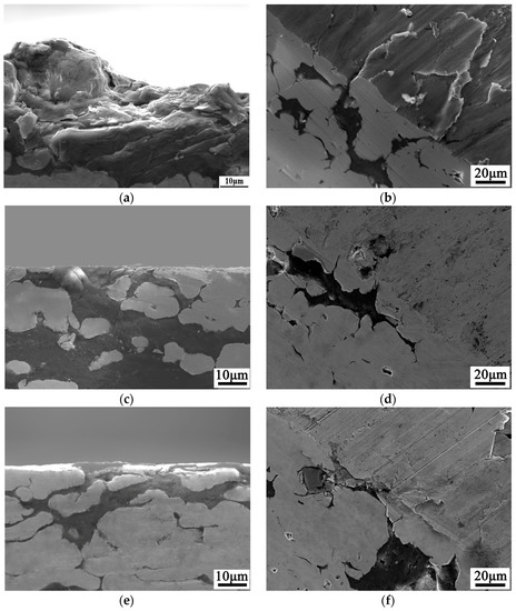
Figure 13.
Direct section and oblique section SEM analysis. (a) O6 direct section; (b) O6 oblique section; (c) C6 direct section; (d) C6 oblique section; (e) N6 direct section; (f) N6 oblique section.
SEM analysis was performed on the wear scraps generated in the wear testing of the O6, C6, and N6 disks, and the results of the analysis are depicted in Figure 14. A comparison of the results shows that the size of the grinding chips from the C6 and N6 disks is much smaller than that from the O6 disks. The chip size from the O6 disk is about 107.7 μm, whereas the chip sizes from the C6 and N6 disks are flake-like and massive, respectively. Specifically, the size of the C6 chip is 1.4 μm, and that of the N6 chip is 1.1 μm. This implies that without graphite coating, the grinding chip’s formation mode is that the graphite splits the matrix and leads to spalling off, with graphite failure occurring without lubrication. After Ni and Cu plating on the surface of the graphite powder, the wear surface of the disk sample experiences fatigue and forms abrasive chips, which are flakier. However, both the number and size of the N6 chips are smaller than those of C6, indicating that there was less fatigue failure of the wear surface of the N6 disk samples. Consequently, the effect of Ni plating on the wear resistance of Cu-based self-lubricating materials is superior to that of Cu plating.
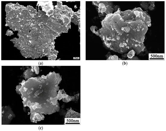
Figure 14.
SEM analysis of wear scraps. (a) O6 sample; (b) C6 sample; (c) N6 sample.
5. Conclusions
- (1)
- The coefficient of friction and wear weight loss of Cu-based self-lubricating materials decreased with an increase in graphite content after Cu and Ni plating on the graphite surface, reaching a minimum value at a graphite content of 6 wt.%. The coefficient of friction and wear weight loss of the Ni-plated material were reduced 11.1% and 85.6%, respectively, whereas the coefficient of friction and wear weight loss of the Cu-plated materials were reduced 7.2% and 78.4%, respectively. The coefficient of friction and wear weight loss of the Ni-plated materials were lower than those of the Cu-plated materials. When the graphite content of the non-plated material was 4 wt.%, the minimum coefficient of friction and the minimum wear weight loss were 0.153 and 2.832 g·m−3, respectively, which are much higher than the minimum coefficient of friction and wear weight loss after Cu and Ni plating. Ni plating displayed superior improvement in friction and wear performance of Cu-based self-lubricating materials as compared to Cu plating.
- (2)
- In the wear process of the non-plated Cu-based self-lubricating materials, graphite spalled from the matrix. Due to the weak bonding strength with the graphite interface, the wear surface undergoes a large amount of spalling, increasing roughness and raising both coefficient of friction and wear rate. Cu plating on the graphite surface improves the bonding strength between the matrix and graphite, which slightly reduces subsurface spalling. However, Ni plating enhances the bonding strength such that the subsurface of the matrix does not spall during the wear process. Therefore, compared to Cu plating, Ni plating substantially enhances the friction and wear performance of Cu-based self-lubricating materials.
- (3)
- Cu and Ni plating increases the adhesion of materials on the pin surface, and the adhesive materials’ composition is consistent with the lubricating film, which changes the grinding mechanism between the pin and the disk. The pin’s surface has less adhesive material when the graphite is not plated; however, the pair still retains an anti-grinding lubrication film. When the graphite is Cu-plated, the pair changes to form a lubrication film. Conversely, when the graphite is Ni-plated, the grinding pair moves from lubricating film to grinding lubrication film, resulting in the Ni-plated disk sample’s wear surface rarely displaying fatigue failure. Thus, Ni plating has a stronger effect on the tribological performance of Cu-based self-lubricating materials than Cu plating.
Author Contributions
Y.W.: Conceptualization, methodology, investigation, formal analysis, writing—original draft. L.X.: Investigation, funding acquisition. X.L.: Formal analysis, conceptualization, writing—editing. All authors have read and agreed to the published version of the manuscript.
Funding
This research was funded by the Open Fund of the National Joint Engineering Research Centre for Abrasion Control and Moulding of Metal Materials, grant number HKDNM202103.
Data Availability Statement
The data used to support the findings of this study are available from the corresponding author upon request.
Acknowledgments
We thank Zijun Ren at the Instrument Analysis Centre of Xi’an Jiaotong University for their assistance with SEM analyses.
Conflicts of Interest
The authors declare no conflict Ni of interest.
References
- Luo, Y. Research on the switch slide baseplates under the conditions of dry friction. J. Shanghai Tiedao Univ. 1998, 19, 37–42. [Google Scholar]
- Bishop, D.M.; Chambers, J. Plastic dry bearings in switch slide baseplates. J. Rep. Proc. Perm. Way Inst. 1990, 108, 155–173. [Google Scholar]
- Li, X.; Gao, Y.; Xing, J.; Wang, Y.; Fang, L. Wear reduction mechanism of graphite and MoS2 in epoxy composites. Wear 2004, 257, 279–283. [Google Scholar] [CrossRef]
- Kováčik, J.; Emmer, Š.; Bielek, J.; Keleši, L. Effect of composition on friction coefficient of Cu–graphite composites. Wear 2008, 265, 417–421. [Google Scholar] [CrossRef]
- Manory, R. A novel electrical contact material with improved self-lubrication for railway current collectors. Wear 2001, 249, 626–636. [Google Scholar]
- Shen, W.; Cui, D.; Shi, Y. Research and manufacture of self-lubricating switch glide. China Railw. Sci. 1998, 19, 103–110. [Google Scholar]
- Dong, R.; Cui, Z.; Zhu, S.; Xu, X.; Yang, X. Preparation, Characterization and Mechanical Properties of Cu-Sn Alloy/Graphite Composites. Metall. Mater. Trans. A 2014, 45, 5194–5200. [Google Scholar] [CrossRef]
- Wang, Y.; Gao, Y.; Li, Y.; Li, M.; Sun, L.; Zhai, W.; Li, K. Research on synergistic lubrication effect of silver modified Cu–Ni-graphite composite. Wear 2020, 444–445, 203140. [Google Scholar] [CrossRef]
- Cao, J.; Li, F.; Yang, Q.; Zhan, K.; Yang, Z.; Wang, Z.; Zhao, B. A review on interfacial structure optimization and its mechanism on the properties of carbon reinforced metal-matrix composites. Compos. Interfaces 2023, 30, 543–583. [Google Scholar] [CrossRef]
- Miranda-López, A.; León-Patiño, C.A.; Aguilar-Reyes, E.A.; Bedolla-Becerril, E.; Rodriguez-Ortiz, G. Effect of graphite addition on wear behaviour of hybrid Cu/TiC-Gr infiltrated composites. Wear 2021, 484–485, 203793. [Google Scholar] [CrossRef]
- Kato, H.; Takama, M.; Iwai, Y.; Washida, K.; Sasaki, Y. Wear and mechanical properties of sintered copper–tin composites containing graphite or molybdenum disulfide. Wear 2003, 255, 573–578. [Google Scholar] [CrossRef]
- Wang, X.; Su, Y.; Wang, X.; Liu, K.; Zhang, L.; Ouyang, Q.; Zhang, D. Fabrication, mechanical and thermal properties of tungsten-copper coated graphite flakes reinforced copper matrix composites. Mater. Des. 2022, 216, 110526. [Google Scholar] [CrossRef]
- Kestursatya, M.; Kim, J.K.; Rohatgi, P.K. Friction and wear behavior of a centrifugally cast lead-free copper alloy containing graphite particles. Metall. Mater. Trans. A 2001, 32, 2115–2125. [Google Scholar] [CrossRef]
- Kumar, P.S.; Manisekar, K.; Narayanasamy, R. Experimental and Prediction of Abrasive Wear Behavior of Sintered Cu-SiC Composites Containing Graphite by Using Artificial Neural Networks. Tribol. Lett. 2014, 57, 455–471. [Google Scholar]
- Moustafa, S.F.; El-Badry, S.A.; Sanad, A.M.; Kieback, B. Friction and wear of copper–graphite composites made with Cu-coated and uncoated graphite powders. Wear 2002, 253, 699–710. [Google Scholar] [CrossRef]
- Zhu, J.M.; Li, J.W.; Liu, T.; Chen, Z.; Fang, H.C.; Xiao, P.; Kong, F. Differences in mechanical behaviors and characteristics between natural graphite/copper composites and carbon-coated graphite/copper composites. Mater. Charact. 2020, 162, 110195. [Google Scholar] [CrossRef]
- Wang, Y.; Gao, Y.; Li, Y.; Zhang, C.; Sun, L.; Zhai, W. Research on nickel modified graphite/Cu composites interface. Surf. Coat. Technol. 2017, 328, 70–79. [Google Scholar] [CrossRef]
- Wang, Y.; Gao, Y.; Takahashi, J.; Wan, Y.; He, X.; Zhang, Y.; Xiao, B.; Zhang, C. The study of microstructure characterization: Cu modified Cu-Ni-graphite composite. Compos. Interfaces 2019, 26, 249–262. [Google Scholar] [CrossRef]
- Wu, L.; Yang, H.; Cheng, J.; Hu, C.; Wu, Z.; Feng, Y. Review in preparation and application of nickel-coated graphite composite powder. J. Alloys Compd. 2021, 862, 158014. [Google Scholar] [CrossRef]
- Yuan, Y.; Gan, X.; Lai, Y.; Zhao, Q.; Zhou, K. Microstructure and properties of graphite/copper composites fabricated with Cu-Ni double-layer coated graphite powders. Compos. Interfaces 2020, 27, 449–463. [Google Scholar] [CrossRef]
- Chen, S.; Gan, X.; Zhao, Q.; Cheng, J.; Zhou, K. Properties and microstructure of nickel/graphite composites fabricated by electroless nickel plating and spark plasma sintering. Compos. Interfaces 2020, 27, 419–433. [Google Scholar] [CrossRef]
- Tang, Y.; Yang, X.; Wang, R.; Li, M. Enhancement of the mechanical properties of graphene–copper composites with graphene-nickel hybrids. Mater. Sci. Eng. A 2014, 599, 247–254. [Google Scholar] [CrossRef]
- Markandan, K.; Nagarajan, T.; Walvekar, R.; Chaudhary, V.; Khalid, M. Enhanced Tribological behaviour of hybrid MoS2@Ti3C2 MXene as an effective anti-friction additive in gasoline engine oil. Lubricants 2023, 11, 47. [Google Scholar] [CrossRef]
- Prabhu, T.R.; Varma, V.; Vedantam, S. Tribological and mechanical behavior of multilayer Cu/SiC+Gr hybrid composites for brake friction material applications. Wear 2014, 317, 201–212. [Google Scholar] [CrossRef]
- Chu, H.; Lin, J. Experimental analysis of the tribological behavior of electroless nickel-coated graphite particles in aluminum matrix composites under reciprocating motion. Wear 2000, 239, 126–142. [Google Scholar] [CrossRef]
- Zhan, Y.; Zhang, G.; Wu, Y. Effect of surface metallization of graphite on the tribological properties of copper hybrid composites. Scand. J. Metall. 2004, 33, 80–84. [Google Scholar] [CrossRef]
- Guo, M.; Tsao, C. Tribological behavior of aluminum/SiC/nickel-coated graphite hybrid composites. Mater. Sci. Eng. A 2002, 333, 134–145. [Google Scholar]
- Yin, Y.; Du, C.; Zheng, Z.; Xie, T.; Liu, K.; Wu, Y. Effect of graphite coated with nickel on mechanical properties of copper-matrix/graphite composite materials. Chin. J. Nonferr. Met. 2006, 16, 1895. [Google Scholar]
Disclaimer/Publisher’s Note: The statements, opinions and data contained in all publications are solely those of the individual author(s) and contributor(s) and not of MDPI and/or the editor(s). MDPI and/or the editor(s) disclaim responsibility for any injury to people or property resulting from any ideas, methods, instructions or products referred to in the content. |
© 2023 by the authors. Licensee MDPI, Basel, Switzerland. This article is an open access article distributed under the terms and conditions of the Creative Commons Attribution (CC BY) license (https://creativecommons.org/licenses/by/4.0/).