Article

Wear and Subsurface Stress Evolution in a Half-Space under Cyclic Flat-Punch Indentation

by
Javier M. Juliá
and
Luis Rodríguez-Tembleque
*
Department of Continuum Mechanics and Structures, Escuela Técnica Superior de Ingeniería, Universidad de Sevilla, Camino de los Descubrimientos s/n, 41092 Sevilla, Spain
*
Author to whom correspondence should be addressed.
Lubricants 2023, 11(6), 265; https://doi.org/10.3390/lubricants11060265
Submission received: 25 April 2023 / Revised: 5 June 2023 / Accepted: 12 June 2023 / Published: 17 June 2023
(This article belongs to the Special Issue Advances in Wear Predictive Models)

Abstract

:
Wear is a tremendously important phenomenon, which takes place on the surfaces of two solids in contact under cyclic loads and constitutes one of the most-significant ways of failure for mechanical elements. However, it is not the only source of failure in contacting solids. The subsurface stresses should also be considered, due to the fatigue and crack initiation problems. Nevertheless, these stresses (i.e., their maximum values and distributions) evolve with the solids’ surface wear (i.e., with the load cycles) and also depend on the friction intensity. Therefore, their evolution should be properly computed to predict failures in mechanical elements under wear conditions. This work focused on the study of the evolution of the surface wear and the subsurface stress distributions generated—in an elastic half-space—by a cylindrical flat-ended punch, under cyclic indentation loading (i.e., radial fretting wear conditions). Based on a numerical scheme recently presented by the authors, this is the first time that, for this contact problem, the surface wear and subsurface stress distribution (i.e., maximum value and its location)—and its evolution—were simultaneously analyzed when orthotropic friction and fretting wear conditions were considered. The studies presented in this work were developed for purely elastic contact assumptions.

1. Introduction

Friction and wear are inherent phenomena in the mechanical contact between two elastic bodies. Mechanical contact usually takes place in regions where forces are transmitted between two machine—or structural—components, i.e., in regions of joints, in bearings, in the contact region of a railway track and wheel, etc. Therefore, very high stresses appear at the surface—and subsurface—contact regions of these mechanical components. It should be noted that failure by induced subsurface stresses occurs when these stresses exceed the elastic limits according to a given/pertinent failure criterion. The failure is usually due to fatigue spalling/pitting [1], and that failure occurs when such limiting stresses coincide with subsurface flaws created during manufacturing such as pores, inclusions, cracks, etc. According to [2,3], the behavior of the subsurface stresses allows us to predict cracks’ nucleation and expansion through the solid. However, that stress depends on the friction intensity and, under dynamic or cyclic loading, evolves the surface wear (i.e., with the load cycles).
The surface wear problem has been studied for more than seventy years (i.e., since the pioneering works of Holm [4] and Archard [5]). Since then, many theoretical and computing formulations have been proposed to predict surface wear under several contact conditions. The theoretical works of Galin et al. [6,7], Kovalenko et al. [8,9], Kragelsky [10], and Komogortsev [11] led to the fundamental works of Hills et al. [12,13] and Goryacheva et al. [14] in fretting wear problems. Olofsson et al. [15], Enblom and Berg [16], Telliskivi [17], and Hegadekatte et al. [18] proposed different solutions for rolling contact problems (e.g., for pin-on-disc and twin-disc systems) under sliding wear conditions. More recently, Argatov et al. [19,20,21,22] and Di Puccio and Mattei [23,24] presented additional analytical solutions for sliding wear contact problems and Popov [25] and Cubillas et al. [26] for fretting wear.
Numerical solutions to compute surface wear have also been developed for the last thirty years. The pioneering works of Johansson [27] and Strömberg et al. [28,29,30] made it possible to solve contact problems under fretting wear or sliding wear conditions. These formulations—based on the finite element method (FEM)—were extended to thermoelastic contact problems in [31,32], to more realistic fretting wear problems in [33,34,35,36], and to study sliding wear problems in [37]. Recent works in the finite element context have focused on non-matching mesh schemes (see [38,39]). Numerical schemes based on the boundary element method (BEM)—or on the influence coefficient method (ICM)—were also presented to compute surface wear in contacting elements under: sliding wear [40,41,42,43], fretting wear [44,45,46,47,48], or rolling contact [49,50] conditions. Moreover, the atomistic simulations developed in the works of Aghababaei et al. [51,52] revealed how important the numerical simulations and modeling are becoming to explore wear processes.
Regarding the evaluation of the subsurface stresses, several works have been carried out since the pioneering works [53,54,55,56] or the monograph [57] were presented. Some of these recent studies were focused on the elastic line contact problem under dry contact conditions [58] for layered solids [59,60] or for an inhomogeneous elastic medium [61]. Subsurface stresses under lubricated elastic line contact conditions were analyzed in [62,63,64]. For point contact conditions, a comprehensive analysis of the subsurface stresses caused by a Hertzian ellipsoidal pressure distribution was provided by Sackfield and Hills in [65,66] and, more recently, by Greenwood [67]. The analysis of the subsurface stresses caused by any arbitrary pressure distribution was presented by Johns-Rahnejat and Gohar in [68]. The interest in the subsurface stress distributions caused by contact and how they can be affected by friction intensity [2,69,70] or wear [71] has drawn the attention of some researchers in recent years.
In this context, this work studied the evolution of the surface wear and the subsurface stress distributions generated—in an elastic half-space—by a vertically loaded cylindrical flat-ended punch under cyclic normal indentation loading (i.e., conformal contact and radial fretting wear conditions). This problem has been studied for many years, since it is widely present in many mechanical components. The stress distribution caused by a cylindrical flat-ended punch was tackled by Sneddon et al. [72,73] and later by Barquins and Maugis [74], who observed a stress singularity at the edge of the contact region. Later on, these solutions were collected in the fundamental books of Fischer-Cripps [75] and Popov et al. [76], together with the contact pressure distribution. However, to the best of the authors’ knowledge, the surface wear and the subsurface stress distribution (i.e., maximum value and its location)—and their evolution—have not been simultaneously computed and analyzed for this problem. Therefore, this work analyzes—for the first time—the simultaneous evolution of the surface wear and the subsurface stress distribution caused by the indentation of a flat-ended cylindrical punch over an elastic half-space under orthotropic friction and radial fretting wear conditions. Moreover, this is the first time that the BEM was applied to analyze this indentation problem under these tribological contact conditions. For this purpose, the computing framework presented in [71] was extended to analyze the indentation of a flat-ended cylindrical punch over an elastic half-space. That computational scheme was based on the BEM (or ICM) [77,78,79] to obtain the influence coefficients of the contacting solids. The frictional contact problem was solved using an augmented Lagrangian formulation (see [80,81,82]). Then, the subsurface stresses in the contacting solids were computed according to Liu and Wang [83]. This scheme allowed us to study several numerical examples, where the influence of—orthotropic—wear and friction conditions were analyzed. All these numerical studies were developed under purely elastic contact assumptions.
Finally, the structure of this manuscript is organized as follows. After the Introduction, Section 2 presents the kinematic equations for the frictional contact problem including wear. Section 3 focuses on the BEM approximation, which makes it possible to obtain the relations between the surface displacements and the contact tractions. Section 4 defines the contact and wear—orthotropic—laws, and Section 5 presents the equations to compute the subsurface stress distributions. The numerical solution is briefly presented in Section 6. Then, Section 7 presents the analyses, and finally, the concluding remarks are compiled in Section 8.

2. Frictional Contact Kinematics Including Wear

The kinematic description of two elastic bodies ( Ω α , α = A , B ) contacting in common area Γ c needs to define the position x of each solid particle of these two bodies relative to a coordinate system O x y z . In that system, z points are normally oriented and { x , y } are tangentially directed (see Figure 1). Then, the normal gap between these two solids’ surfaces can be defined as
g n ( x , τ ) = g g g n , o ( τ ) + ω ( x , τ ) + u n ( x , τ ) ,
where g g is the geometric gap, g n , o ( τ ) is the rigid body approach at a certain pseudo-time instant ( τ ) and u n is the relative surface normal displacement: u n ( x , τ ) = u z ( A ) ( x , τ ) u z ( B ) ( x , τ ) .
The tangential slip displacements are defined as
g t ( x , τ ) = g t , o ( τ ) + u t ( x , τ ) ,
where g t , o ( τ ) is the rigid body tangential slip displacements and u t ( x , τ ) = u t ( A ) ( x , τ ) u t ( B ) ( x , τ ) = [ u x ( x , τ ) u y ( x , τ ) ] T is defined as the relative surface tangential displacement.
A detailed explanation and a schematic representation of the (relative) surface normal and tangential displacements ( u = u t ( x , τ ) T u n ( x , τ ) T ) at point x can be found in Kalker’s book [84].

3. Boundary Element Approximation

The displacement difference u ( x , τ ) can be computed similarly to [77,85,86], which ignores the inertia effects (i.e., considers a quasi-static description). Under these assumptions, the relation between the deformation u = [ u t ( x , τ ) T u n ( x , τ ) ] T at point x and the contact traction p = [ p t ( x , τ ) T p n ( x , τ ) ] T on points x Γ c can be expressed as
u ( x , τ ) = Γ c ( τ ) A ( x , x ) p ( x , τ ) d x d y .
In Equation (3), A ( x , x ) is the kernel function matrix, which quantifies the surface displacement components at x induced by one of the traction components of unit magnitude acting at x . It can be written as
A ( x , x ) = A x x ( x , x ) A x y ( x , x ) A x z ( x , x ) A y x ( x , x ) A y y ( x , x ) A y z ( x , x ) A z x ( x , x ) A z y ( x , x ) A z z ( x , x ) ,
where
A x x ( x , x ) = 1 π G 1 ν s + ν ( x x ) 2 s 3 , A x y ( x , x ) = ν π G ( x x ) ( y y ) s 3 , A y y ( x , x ) = 1 π G 1 ν s + ν ( y y ) 2 s 3 , A y z ( x , x ) = K π G y y s 2 , A z z ( x , x ) = 1 π G 1 ν s , A x z ( x , x ) = K π G x x s 2 , A y x ( x , x ) = A x y ( x , x ) , A z x ( x , x ) = A x z ( x , x ) , A z y ( x , x ) = A y z ( x , x ) ,
where s = ( x x ) 2 + ( y y ) 2 and G, ν , and K are the material parameters, defined as
1 G = 1 2 1 G ( A ) + 1 G ( B ) , ν G = 1 2 ν ( A ) G ( A ) + ν ( B ) G ( B ) , K = G 4 1 2 ν ( A ) G ( A ) 1 2 ν ( B ) G ( B ) .
The terms of Equation (4) can also be expressed as: A ( x , x ) = A ( x x ) , i.e., indicating that the influence coefficients depend on the relative positions of the two surface points x and x .

4. Contact and Wear Laws

4.1. Normal Contact Restrictions

Signorini’s unilateral contact conditions for the normal gap g n ( x , τ ) and the normal contact pressure p n = p z ( x , τ ) can be expressed, according to Alart and Curnier [87], as
p n P R + ( p n * ) = 0 ,
where P R + ( ) = m a x ( 0 , ) is the normal projection function and p n * = p n + r n g n is the augmented normal traction— r n being the normal penalty parameter ( r n R + ).

4.2. Tangential Contact Restrictions

Similarly, the frictional contact constraints can also be formulated, according to [88], as
p t P E ρ ( p t * ) = 0 ,
where p t * = p t r t M 2 g ˙ t is the augmented tangential traction (where M = d i a g ( μ 1 , μ 2 ) and r t R + ) and P E ρ ( ) : R 2 R 2 is the tangential projection function:
P E ρ ( p t * ) = p t * if | | p t * | | μ < ρ , ρ p t * / | | p t * | | μ if | | p t * | | μ ρ .
In the expression above, ρ = | P R + ( p n * ) | and the elliptic norm | | | | μ is defined, so that
| | p t | | μ = p e 1 / μ 1 2 + p e 2 / μ 2 2 ,
where μ 1 and μ 2 are the principal friction coefficients in the directions { e 1 , e 2 } . Moreover, the tangential contact tractions’ components—and the tangential slip velocity components—can be expressed in the tribological axes { e 1 , e 2 } as
p e 1 p e 2 = cos β sin β sin β cos β p x p y ,
where the angle β is defined in [71] as the tribological axes’ angle orientation. In the expression above, the tangential slip velocity g ˙ t can be expressed at time τ k as follows: g ˙ t Δ g t / Δ τ (see [88,89,90]), where Δ g t = g t ( τ k ) g t ( τ k 1 ) and Δ τ = τ k τ k 1 .

4.3. Wear Law

This work assumed a Holm–Archard wear law [91], which, for an infinitesimally small apparent contact area, can be expressed in terms of the wear rate [33,43,47,49,50,92,93,94,95], as: ω ˙ = i w | p n | | | g ˙ t | | , i w being the wear coefficient.
Since orthotropic tribological properties were considered in this work, an orthotropic wear law [50,96,97] should be assumed. Therefore, the wear law should be rewritten as
ω ˙ = | p n | | | g ˙ t | | i ,
where
| | g ˙ t | | i = ( i 1 g ˙ e 1 ) 2 + ( i 2 g ˙ e 2 ) 2 ,
where i 1 and i 2 are the principal intensity wear coefficients.
The derivatives can be expressed—under quasi-static wear and contact conditions as ω ˙ Δ ω = ω ( τ k ) ω ( τ k 1 ) and g ˙ t Δ g t = g t ( τ k ) g t ( τ k 1 ) . Therefore, the wear depth at the instant τ k can be computed as
ω ( τ k ) = ω ( τ k 1 ) + p n ( τ k ) | | g t ( τ k ) g t ( τ k 1 ) | | i .

5. Subsurface Stresses

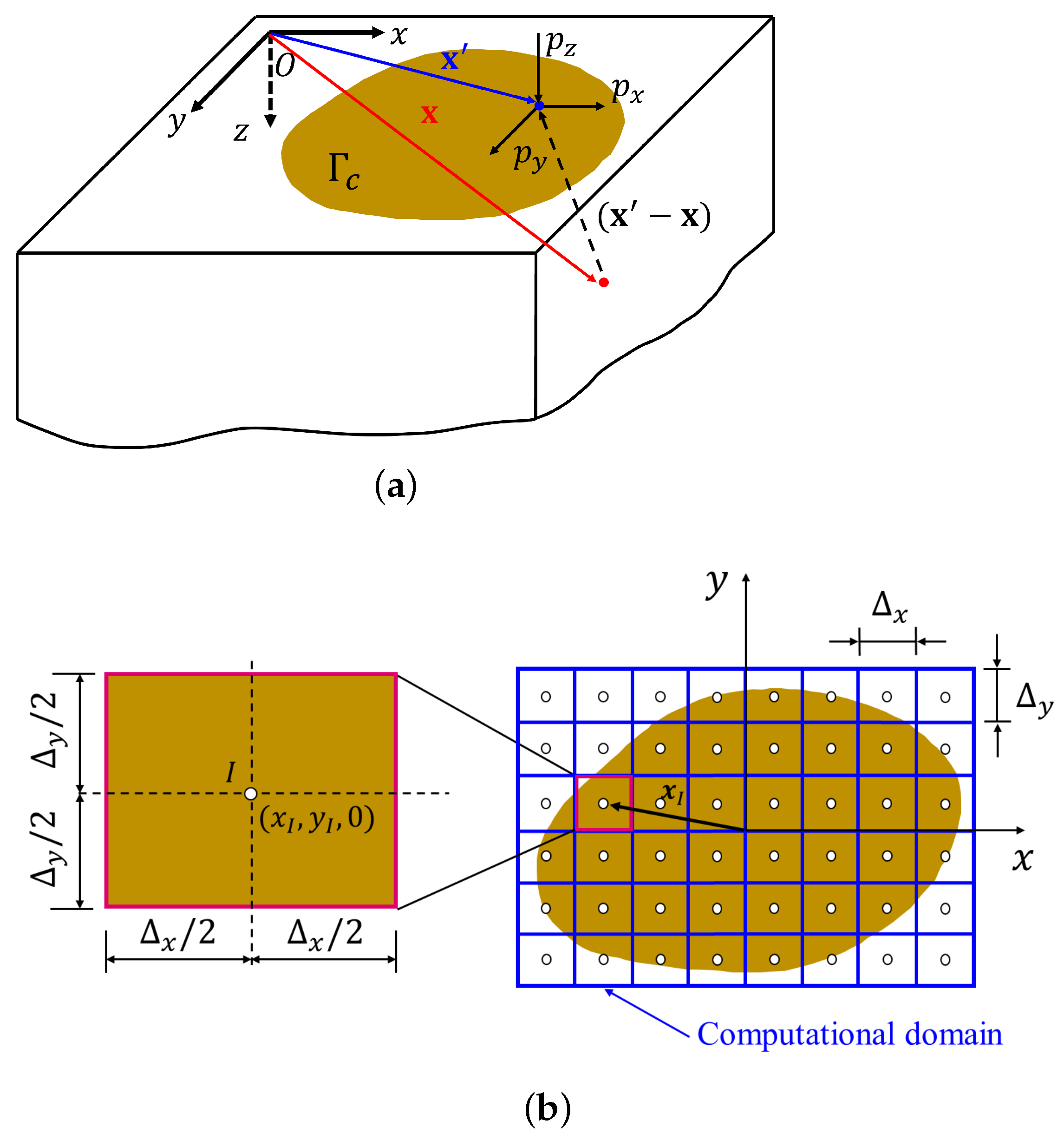
Finally, the subsurface stresses at point x Ω ( α ) ( α = A , B )—caused by a surface contact pressure at x Γ c (see Figure 2a)—can be computed as
σ ( x , τ ) = Γ c ( τ ) T ( x , x ) p ( x , τ ) d x d y ,
where the influence coefficients of the kernel function T ( x , x ) depend on the relative positions of the two surface points x and x ; therefore, T ( x , x ) = T ( x x ) .
For the sake of clarity, the expression above is rewritten as
σ i j ( x , τ ) = Γ c ( τ ) T i j S x ( x x ) p x ( x , τ ) + T i j S y ( x x ) p y ( x , τ ) + T i j N ( x x ) p n ( x , τ ) d x d y .
The explicit expressions of T i j N ( x , y , z ) , T i j S x ( x , y , z ) and T i j S y ( x , y , z ) can be found in [71].

6. Solution Scheme

The nonlinear equations’ set Equations (1)–(3), (7), (8), (14) and (16) was discretized and solved by using the numerical scheme presented by the authors in [71]. This allowed us to compute the contact conditions and the subsurface stresses’ evolution caused by the contact—under wear conditions—on every loading and unloading cycle (k). For the numerical simulation, a rectangular potential contact zone was considered and discretized by a regular mesh with N e = N x × N y elements of size Δ x × Δ y (see Figure 2b), whose coordinates were the center of each element. Subsurface stresses for a set of interior points can be computed from the discrete expression of Equation (16).

7. Numerical Analysis

This work analyzed the influence of friction and wear on the surface and subsurface contact stresses generated—in an elastic half-space—by the cylindrical flat-ended punch, under normal cyclic indentation loading. Moreover, orthotropic tribological laws were also considered in the analysis. For this purpose, we considered a cylindrical punch, whose radius was a o = 1.8 mm. Both domains were constituted by linear and elastic materials with the same Poisson’s ratios ν ( A ) = ν ( B ) = 0.3 and different Young’s modulus, i.e., E ( B ) / E ( A ) = 100 , where E ( A ) = 200 × 10 3 MPa . Therefore, the punch can be considered as rigid compared to the half-space.
This section is divided into three blocks. Firstly, in Section 7.1, we validate the computational framework by solving a benchmark frictionless indentation problem—under static normal load (P)—whose theoretical surface contact tractions and subsurface stress distributions can be found in the literature [76,98]. In this context, the influence of friction was also studied. Therefore, considering several values of the friction coefficient ( μ ), we can study its influence on the contact tractions and the subsurface stresses. Secondly, in Section 7.2, the cylindrical flat-punch is subjected to a cyclic normal load—loading and unloading cycles—which induces wear on the solids’ surfaces, i.e., fretting wear conditions. Therefore, this section studies the influence of both friction and wear on the evolution of the surface contact tractions and subsurface contact stresses, assuming isotropic friction and wear laws. Finally, Section 7.3 studies the cylindrical flat-punch under cyclic normal load conditions and orthotropic tribological laws.

7.1. Cylindrical Flat-Punch under Static Normal Load Conditions

First, we validated the accuracy of the proposed formulation to solve this problem by solving the static indentation under frictionless contact conditions ( μ = 0 ). The theoretical solution of this benchmark problem can be found in [76] or [98]. For the normal contact pressure, it can be presented as a function of the radial distance ( r = x 2 + y 2 ) as
p n = P 2 π a o a o 2 r 2 ( r a o ) ,
where P is the centrally applied vertical force. This resulting normal load (P) and the average contact pressure ( p o ) in the contact zone can be written, respectively, as a function of the normal indentation ( g o ) as
P = 2 E * a o g n , o ,
and
p o = P π a o 2 = 2 E * g n , o π a o ,
where E * = ( 1 ν ( A ) 2 ) / E ( A ) + ( 1 ν ( B ) 2 ) / E ( B ) 1 .
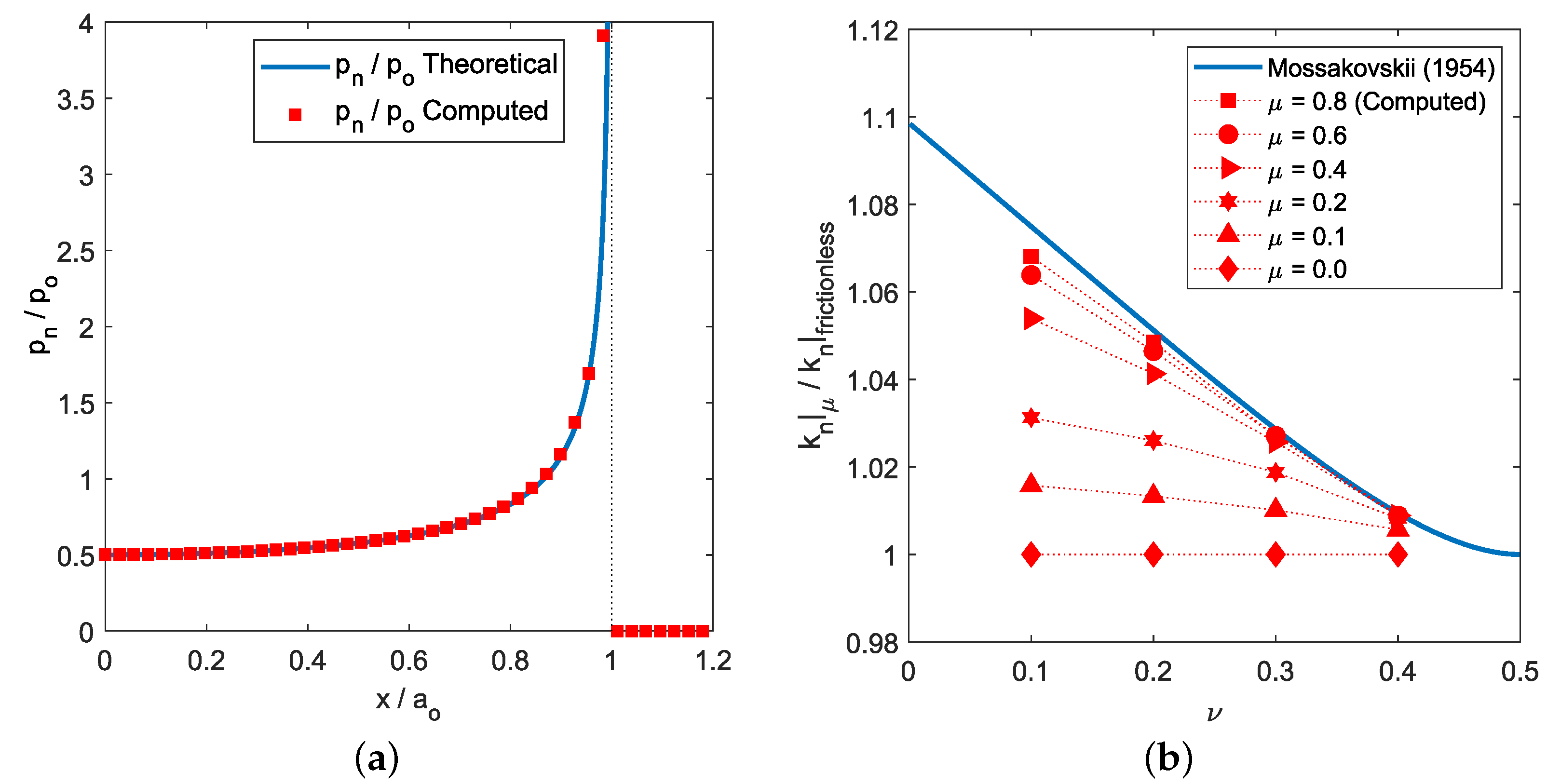
A comparison between the theoretical normal contact pressure distribution, for P = 714 N ( g n , o = 9113.4 µm), and the numerical results is presented in Figure 3a. In this figure, all the variables are presented in a non-dimensional form. The x-axis coordinates are expressed relative to a o , and the normal contact pressure is presented relative to p o . This value can be related to the average pressure in the contact ( p o ). An excellent agreement between the numerical results—square markers—and the theoretical solution—continuous line—can be observed in Figure 3a, the maximum values of the normal contact pressure ( p n , m a x ) being located at the contact zone limits, i.e., at x / a o 1.0 .
Now, we can study the influence of friction on the surface contact tractions.
The normal contact of a rigid flat-ended cylindrical punch with an elastic half-space under complete stick conditions was initially solved by Mossakovskii [99]. This work provided us the contact stiffness ( k n : = P / g n , o ), i.e., the ratio between the load on the punch (P) and the indentation ( g n , o ), for the mentioned tangential stick conditions. Therefore, this contact stiffness can be related to the contact stiffness for the frictionless case, presented in Equation (18). The resulting relation between the contact stiffness for the complete stick and for frictionless contact can be expressed as
k n | a d h e s i o n / k n | frictionless = ( 1 ν ) ln ( 3 4 ν ) / ( 1 2 ν ) .
Figure 3b shows the relation between the computed contact stiffness for frictional and for frictionless contact ( k n | μ / k n | frictionless ) as a function of the friction coefficient ( μ ) and the material parameter ν . Moreover, the relation between the contact stiffness for the complete stick and for frictionless contact ( k n | a d h e s i o n / k n | frictionless )—presented by Mossakovskii [99]—is also included. We can observe how the computed k n | μ tends to the contact stiffness for the complete stick case ( k n | a d h e s i o n ) when high values for the friction coefficient are considered. In particular, for the material properties considered ( ν = 0.3 ), the contact stiffness value reached the adhesion case values ( k n | μ k n | a d h e s i o n ) when μ 0.4 .
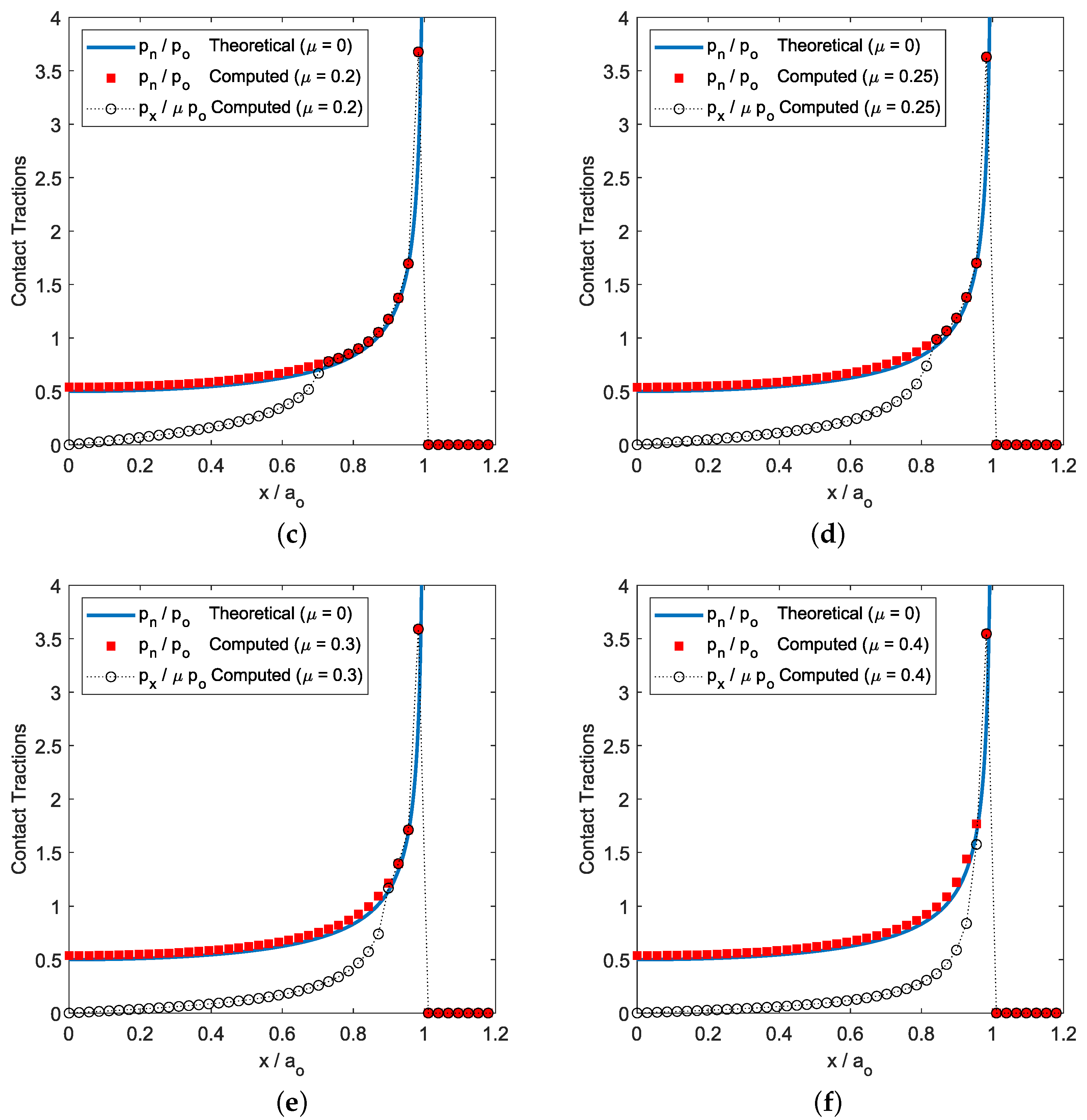
In Figure 4, we present the normal and tangential contact tractions’ distributions under isotropic frictional contact conditions, i.e., μ 1 = μ 2 = μ = { 0.1 , 0.15 , 0.2 , 0.25 , 0.3 , 0.4 } . The results showed how the stick (or adhesion) region in the contact zone (i.e., where | p x | < μ p o ), increased with the value of the friction coefficient ( μ ) until a threshold value is reached (i.e., μ 0.4 in our analysis). Then, all the points of the contact area reached a contact–stick state, and additional increments on μ did not cause an increment on the tangential contact tractions.
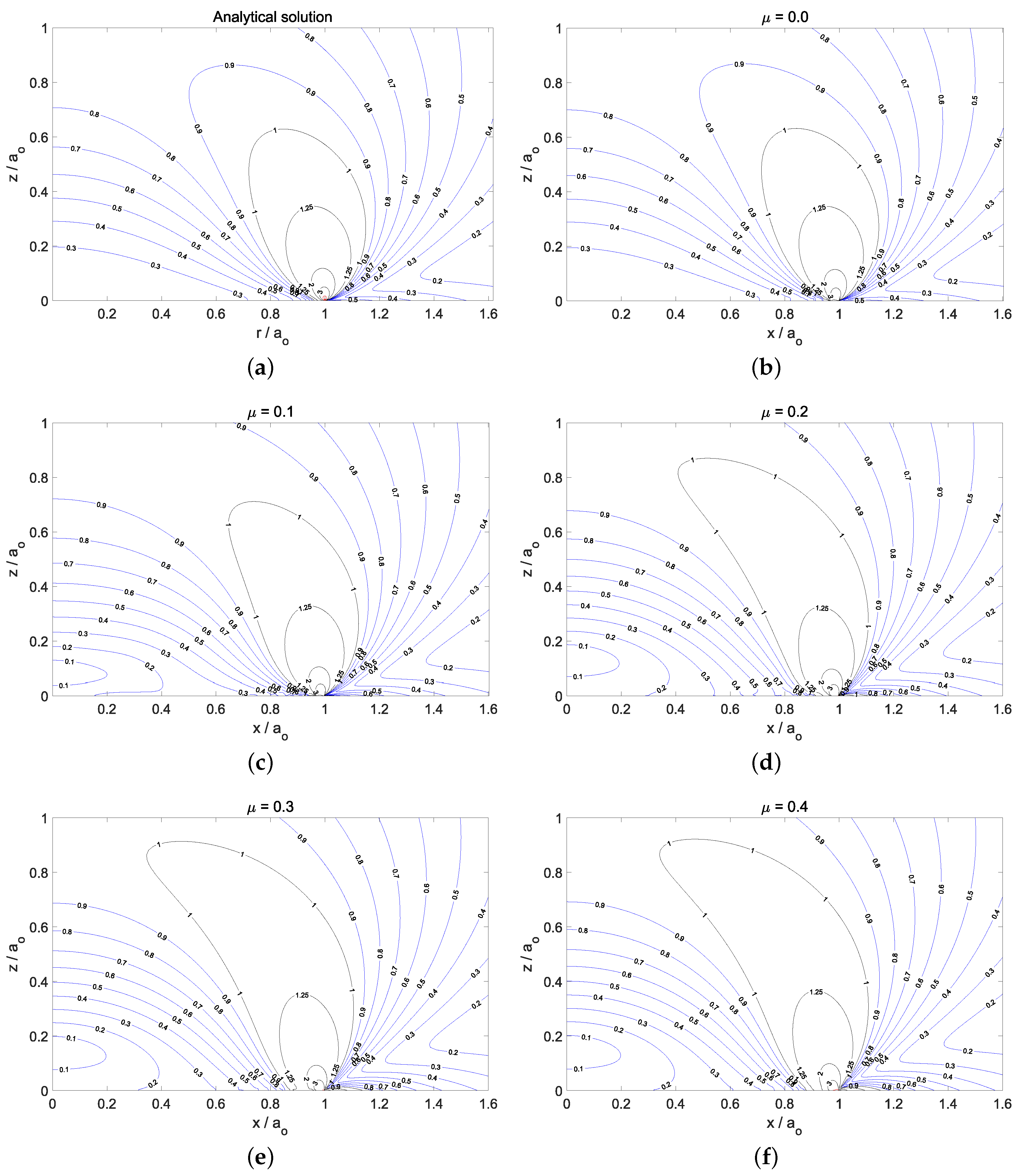
To validate the subsurface stress components’ computational framework, Figure 5a,b presents, respectively, the theoretical and numerical von Mises equivalent stress distributions in the x-z-plane of the elastic half-space, normalized by p o . We can observe an excellent agreement between the theoretical von Mises stress distribution—presented in Figure 5a—and the numerical solution for the frictionless case: μ 1 = μ 2 = μ = 0 ; see Figure 5b. The theoretical von Mises equivalent stress presented in Figure 5a can be obtained from
σ V M = 1 2 ( σ r r σ ϕ ϕ ) 2 + ( σ ϕ ϕ σ z z ) 2 + ( σ z z σ r r ) 2 + 6 τ r z 2 ,
where the expressions of the cylindrical stress components are presented in Appendix A. We can see in Figure 5a how a stress singularity exists at the edge of the contact circle ( r = a o ).
It should be noted that we considered the von Mises failure criterion since ductile contacting bodies—under elastic half-space assumptions—were considered in the analyses. This criterion would not be valid for hardened surfaces or hard wear-resistant coatings such as ceramics. For layered surfaces, the readers should refer to the work of Teodorescu et al. [60].
Once the subsurface stresses were validated, we studied the influence of friction on the subsurface von Mises stress distribution in Figure 5b–f. For the frictionless case, the maximum values of the normalized von Mises stress distribution ( σ V M / p o ) were located at x / a o = 1.0 and z / a o = 0.0 . We also can distinguish a subsurface region, where σ V M / p o 1 (marked with black lines in the figures). Moreover, when we increased the friction intensity, i.e., μ 1 = μ 2 = μ = { 0.1 , 0.2 , 0.3 , 0.4 } , the normalized von Mises stress distributions presented in Figure 5c–f increased the size of the region with σ V M / p o 1 and, additionally, created a new stress gradient around the z-axis. However, when the friction intensity reached the mentioned threshold value, no more changes were observed in the normalized von Mises stress distribution.

7.2. Cyclic Normal Load Conditions and Isotropic Tribological Laws

This section studies the influence of the friction intensity on the evolution of the surface tractions and subsurface stresses when the solids are subjected to—isotropic—fretting wear conditions. In this case, the cylindrical flat-ended punch was subjected to normal indentation loading and unloading cycles over the elastic half-space (see Figure 1), the maximum load value being P = 750 N. The analyses were developed considering different values of the friction coefficients, i.e., μ 1 = μ 2 = μ (where μ = { 0.1 , 0.2 , 0.4 } ), and the wear coefficients values: i 1 = i 2 = i ω (where i ω = 1.33 × 10 7 MPa 1 ).
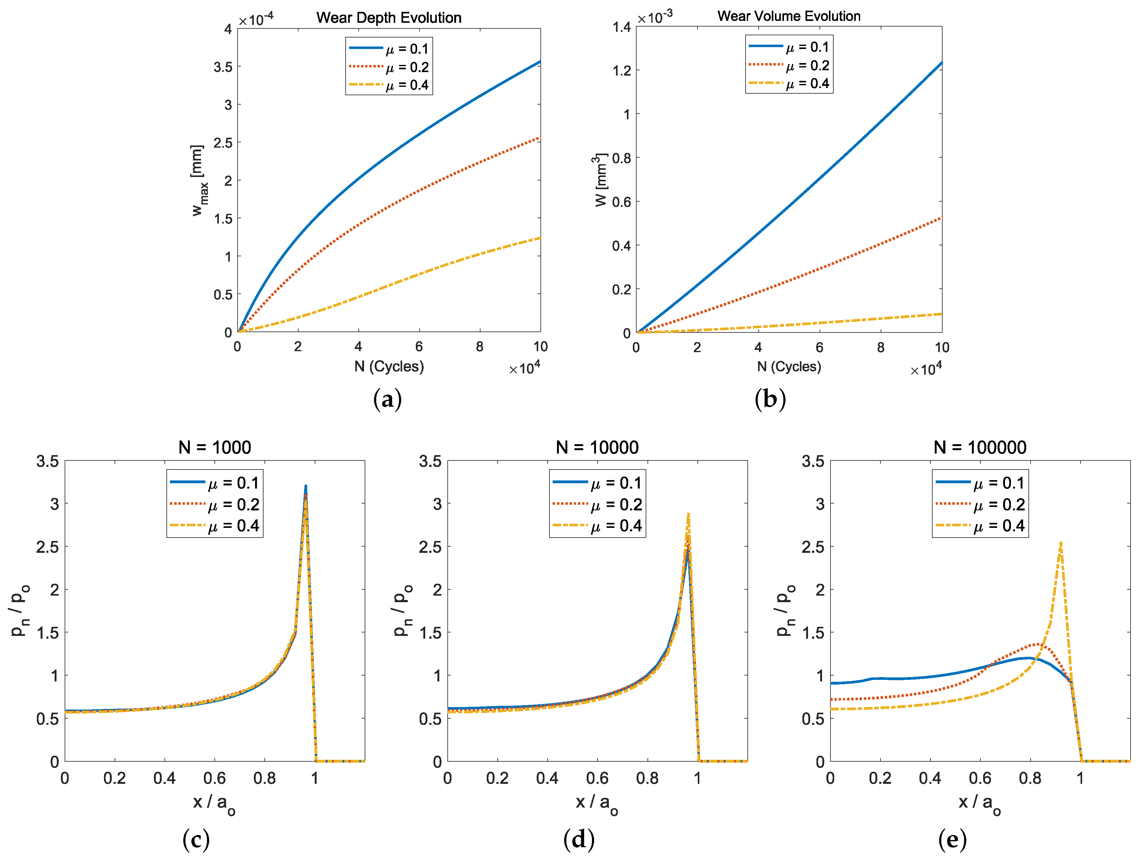
The influence of the friction intensity is clearly observed in Figure 6. We can see in Figure 6a the computed maximum wear depth evolution as a function of the number of load cycles (N), for several values of the friction coefficient: μ = { 0.1 , 0.2 , 0.4 } . Figure 6b shows the wear volume evolution with the number of load cycles and the same values of the friction coefficient. In both figures, we can observe how the smaller the friction coefficient value was, the greater the wear damage (i.e., maximum wear depth or wear volume) obtained. This was due to the fact that the smaller the friction coefficient value was, the bigger the annular sliding contact zone obtained (see Figure 4a,f).
The influence of the friction intensity in the evolution of the normal contact pressure distribution is presented in Figure 6c–e. They present the normal contact pressure distributions after 10 3 , 10 4 , and 10 5 load cycles, respectively, and several friction values of the friction coefficient: μ = { 0.1 , 0.2 , 0.4 } . We can observe in Figure 6e the tremendous difference between the normal contact pressure distribution obtained—after 10 5 load cycles—for μ = 0.1 and μ = 0.4 , respectively.
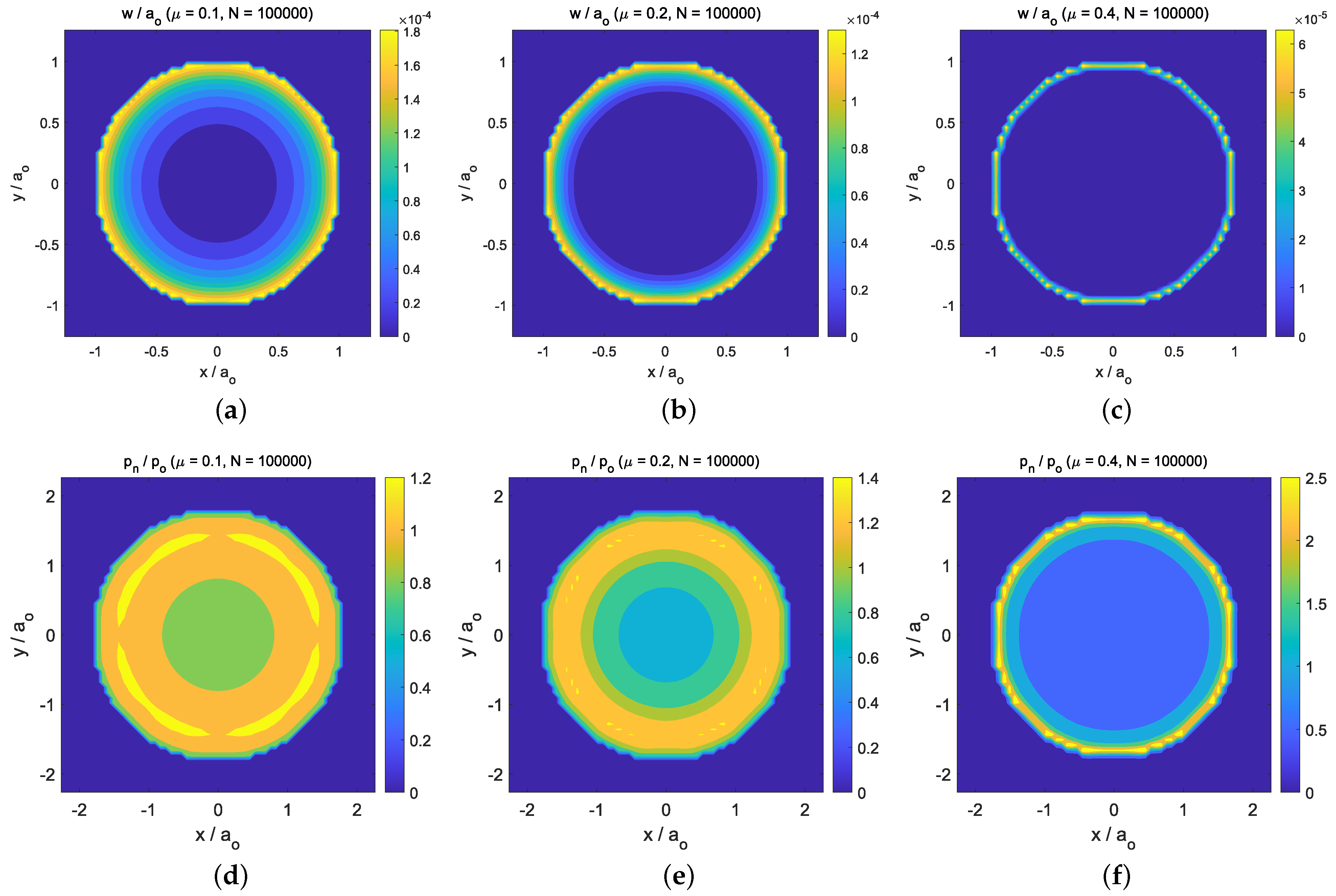
These differences can also be observed in Figure 7a–f for the computed wear depth distributions and normal contact pressure distribution, respectively. These surface distributions are presented in the x-y-plane, after N = 10 5 cycles, for the friction coefficient values: μ = { 0.1 , 0.2 , 0.4 } . Due to the isotropic friction and wear laws considered, the distributions presented a z-axis symmetry.
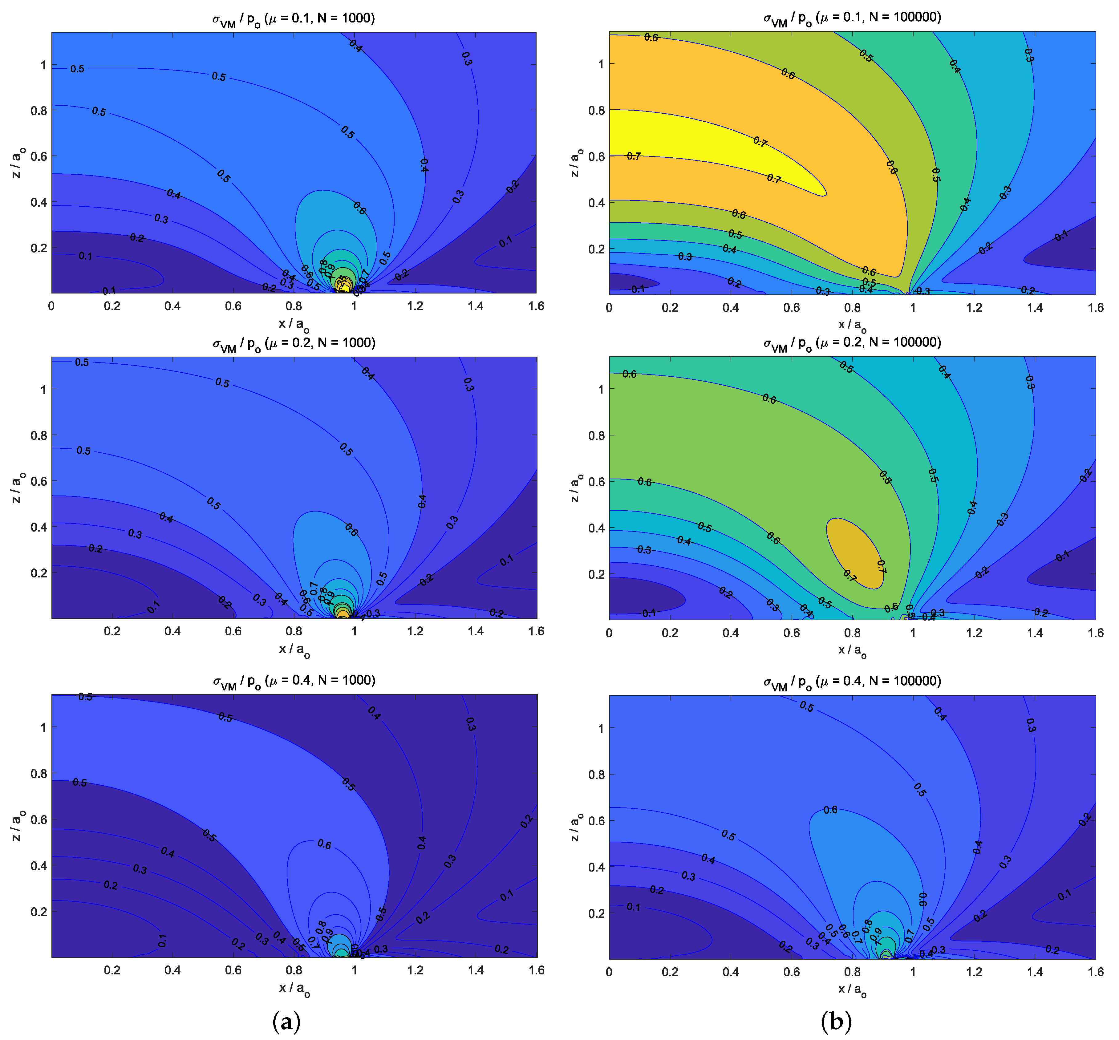
Finally, Figure 8 presents the subsurface von Mises stress distributions in the halfspace after N = 10 3 cycles (see Figure 8a) and N = 10 5 cycles (see Figure 8b), for μ = { 0.1 , 0.2 , 0.4 } , respectively. The stress distributions are presented in the x-z-plane, all the variables being non-dimensional. All the subsurface stress distributions obtained for μ = { 0.1 , 0.2 , 0.4 } after a low number of cycles ( N = 10 3 )—see Figure 8a—presented a maximum stress value at the edge of the contact circle, its radius being slightly reduced from a o due to wear. However, after a big number of load cycles (i.e., N = 10 5 ), the friction intensity had a big influence not only on the resulting values of the von Mises stress, but also on the location of the maximum stress value—see Figure 8b. On the one hand, since low friction values (i.e., μ = 0.1 ) caused important wear damage on the solid surfaces, this also led to a stress distribution where the maximum value of the subsurface von Mises stress was located at r = 0 and z / a o 0.7 . On the other hand, when high friction values were considered (i.e., μ = 0.4 ), low wear damage was produced on the solid surfaces, and therefore, the stress distribution presented its maximum value located on the surface z / a o 0 and at the edge of the contact circle ( r / a o 0.9 ).

7.3. Cyclic Normal Load Conditions and Orthotropic Tribological Laws

This section studies the influence of orthotropic friction and wear laws (i.e, under μ 1 μ 2 and i 1 i 2 ) on the evolution of the surface tractions and the subsurface stresses when fretting wear conditions are considered. Similar to the previous section, the cylindrical flat-ended punch was subjected to normal indentation loading and unloading cycles over the elastic half-space, the maximum load value being P = 750 N. However, in this case, we considered the following values for the friction coefficients: μ 1 = 0.1 and μ 2 = 0.4 , and the wear coefficients: i 1 = 1.33 × 10 7 MPa 1 and i 2 = i 1 μ 2 / μ 1 (in order to maintain that the wear rate is proportional to the friction dissipation energy).
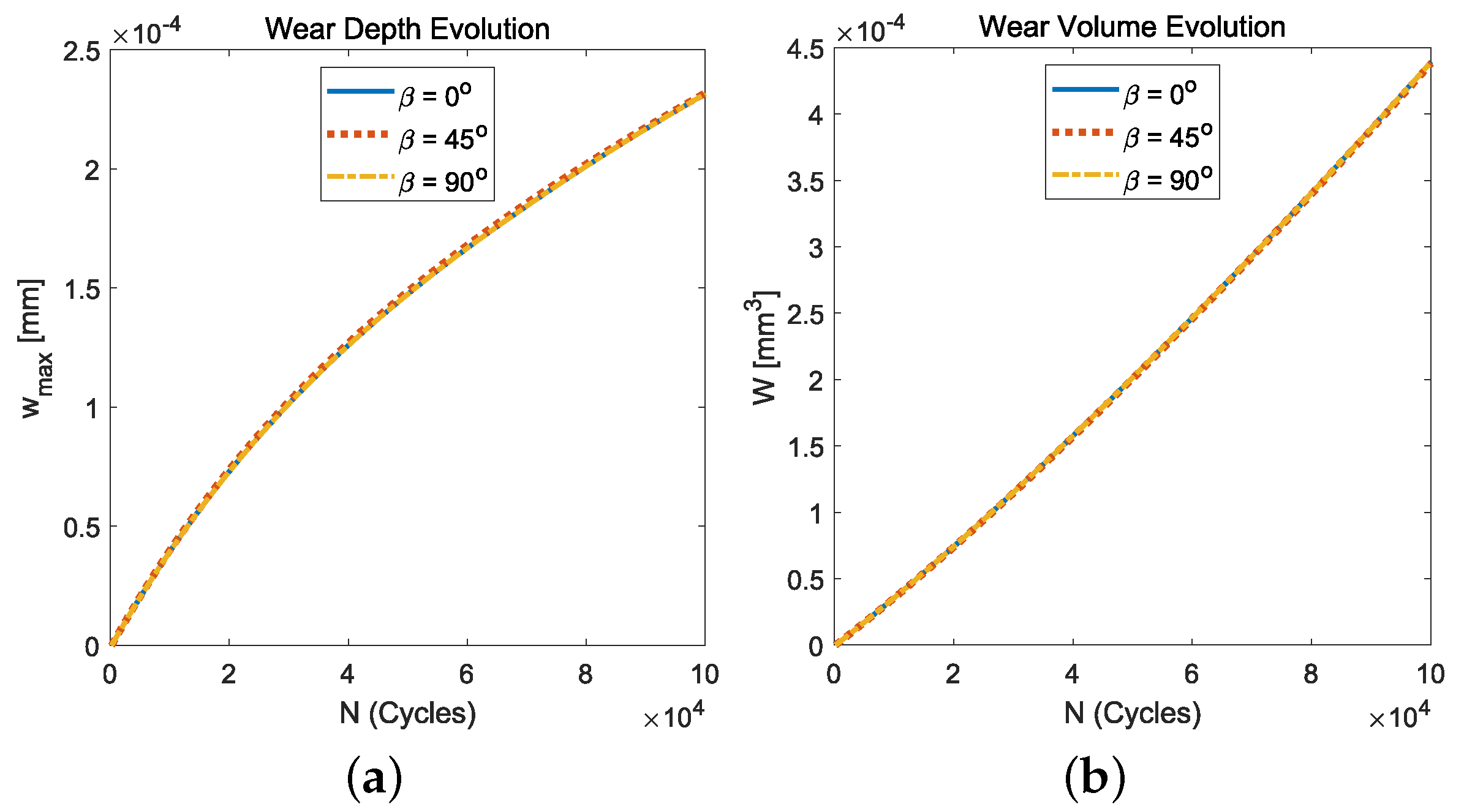
To validate this study, we present in Figure 9a,b the computed maximum wear depth evolution and the total wear volume, respectively, as a function of the number of load cycles (N), for several values of the orientation of the tribological axes’ angles: β = { 0 , 45 , 90 } . In both figures, we can observe how these magnitudes were invariant with the angle β . Additionally, it can be observed that the maximum wear depth evolution for the orthotropic case was similar to the average evolution between the isotropic fretting wear cases presented in Figure 6 for μ = 0.1 and μ = 0.4 . However, the wear volume evolution did not follow that pattern.
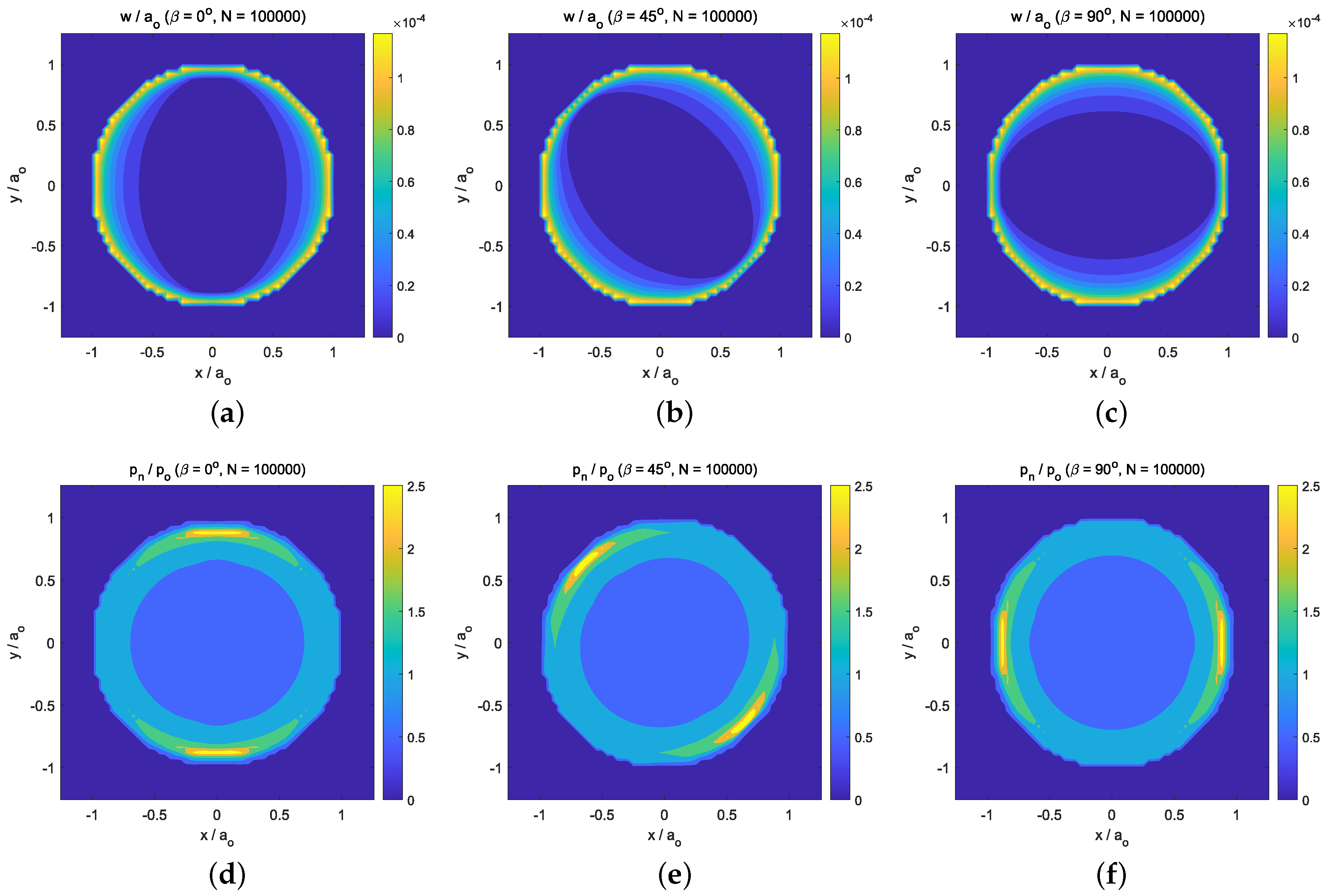
Figure 10a–c present the computed wear depth distribution after N = 10 5 cycles, for the following values of the tribological axes’ angle orientation: β = { 0 , 45 , 90 } , respectively. The resulting normal contact pressure distributions—after N = 10 5 cycles—are presented in Figure 10d–f, for β = { 0 , 45 , 90 } , respectively. Contrary to what Figure 7 showed for the wear depth and the normal contact pressure distributions under isotropic fretting wear conditions, the distributions in Figure 10 for orthotropic fretting wear conditions did not present z-axis symmetry. The maximum value of the normal contact pressure distributions was located where the wear depth distributions presented the greatest gradient values. This region was located at the intersection of the edge of the contact circle and the direction of the tribological principal axis with the greatest friction coefficient (i.e., e 2 -axis in this case, since μ 2 > μ 1 ).
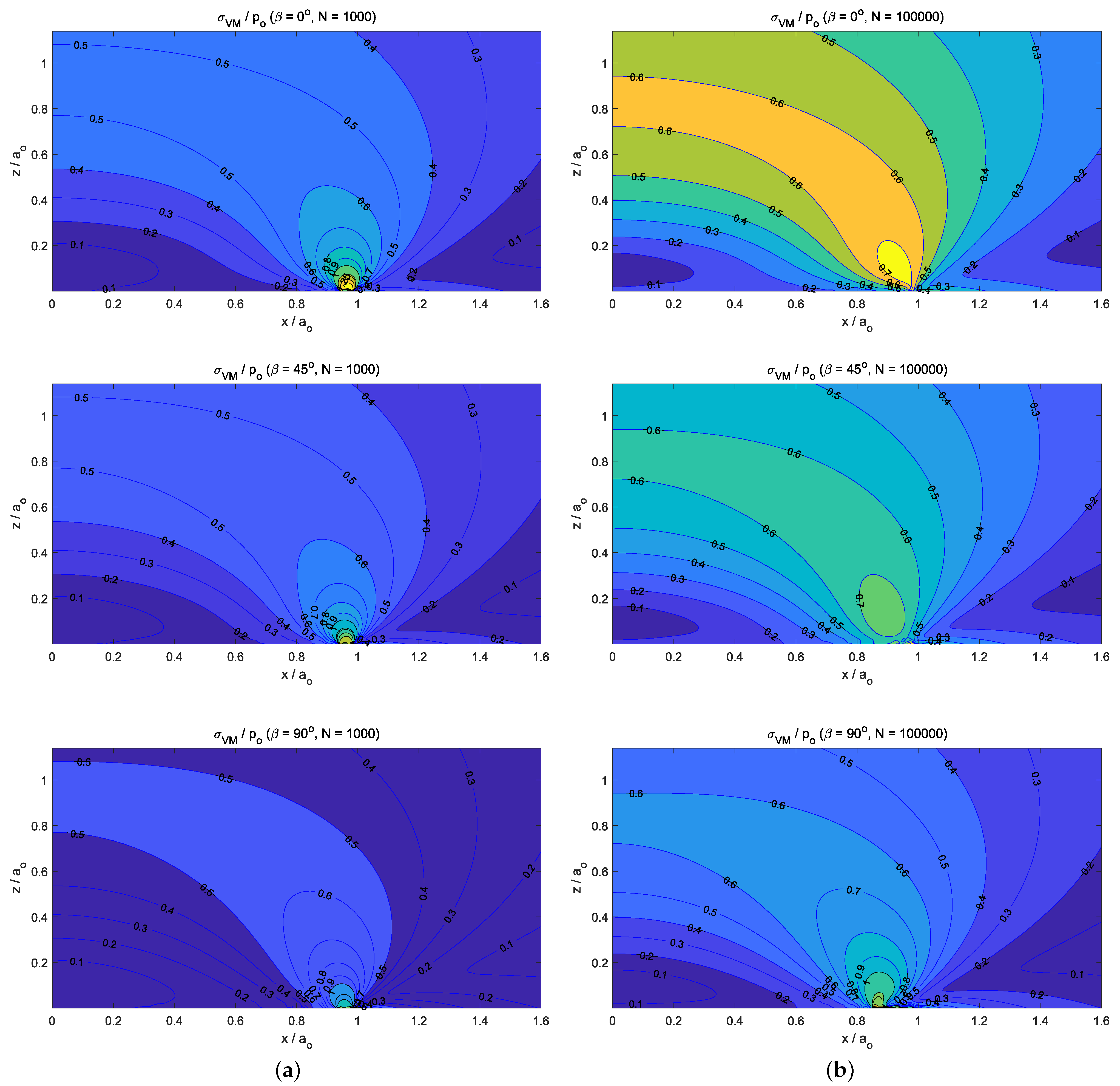
Finally, Figure 11 presents the subsurface von Mises stress distributions in the half-space after N = 10 3 cycles (see Figure 11a) and N = 10 5 cycles (see Figure 11b), for β = { 0 , 45 , 90 }, respectively. Again, the stress distributions are presented in the x-z-plane, all the variables being non-dimensional: The x and z coordinates are expressed relative to a o , and the von Mises equivalent stress is presented relative to p o . All the subsurface stress distributions obtained for β = { 0 , 45 , 90 } after a low number of cycles ( N = 10 3 cycles)—see Figure 11a—presented a stress maximum value at the edge of the contact circle, which, due to wear, was slightly less than a o . The same location of the maximum stress value (i.e., the subsurface region in the edge of the contact circle) was observed after N = 10 5 cycles—see Figure 11b. These discrepancies between the stress distributions obtained under isotropic and orthotropic fretting wear conditions can be explained due to the lack of z-axis symmetry in the wear depth distribution obtained under orthotropic fretting wear conditions.

8. Summary and Conclusions

This work analyzed the influence of friction and wear on the surface and subsurface contact stresses generated—in an elastic half-space—by a cylindrical flat-ended punch, under cyclic indentation loading. For this purpose, the computational framework presented by the authors [71] was extended to study this fretting wear contact problem.
This numerical scheme allowed us to study simultaneously the evolution of the surface wear and the subsurface stress distributions (i.e., maximum value and its location) under orthotropic friction and wear conditions. This allowed us to evaluate the stress distributions in a wide range of engineering components, i.e., especially in those whose surfaces present some particular striation patterns (e.g., caused by machining operations), and highs and hollows were clearly oriented on the surface. For such cases, a specific orthotropic friction and wear law should be considered. However, the formulation presented some limitations. It should be applied to those domains where elastic half-space assumptions can be assumed; therefore, it is not valid for soft surfaces, where small strains cannot be assumed.
After the validation of this computational scheme, several numerical studies were developed to obtain the following conclusions:
  • For the static normally loaded cylindrical flat-punch (see Section 7.1), the stick region in the contact zone increased with the value of the friction coefficient until a threshold value was reached (i.e., μ 0.4 in our analysis). Then, all the points of the contact area reached a contact–stick state. Additionally, on the subsurface von Mises stress distributions (see Figure 5b–f), we observed that the size of the region with σ V M / p o 1 increased with the friction coefficient value—and new stress gradient around the z-axis appeared—until the threshold value was reached. However, when the friction intensity reached the mentioned threshold value, no more changes were observed in the normalized von Mises stress distribution.
  • Regarding the response under isotropic fretting wear conditions caused by the normal cyclic loading conditions (i.e., radial fretting wear), we observed how the smaller the friction coefficient value was, the greater the wear damage (i.e., maximum wear depth or wear volume) obtained. This was due to the fact that the smaller the friction coefficient value was, the bigger the annular sliding contact zone obtained.
  • The influence of friction intensity can be observed—after a big number of load cycles (i.e., N 10 5 )—on the resulting surface wear depth, the normal tractions, and the subsurface von Mises stress values. Due to the fact that isotropic friction and wear laws were considered, their distributions presented a z-axis symmetry. In particular, with regard to the location of the maximum stress value, the low friction values (i.e., μ = 0.1 ) caused important wear damage on the solid surfaces. Moreover, this also led to a stress distribution where the maximum value of the subsurface von Mises stress was located at r = 0 and z / a o 0.7 . On the other hand, when high friction values were considered (i.e., μ = 0.4 ), low wear damage was produced on the solid surfaces, and therefore, the stress distribution presented its maximum value located on the surface z / a o 0 and at the edge of the contact circle ( r / a o 0.9 ).
  • Finally, the response under orthotropic fretting wear conditions caused by the normal cyclic loading conditions did not present a z-axis symmetry. The maximum value of the normal contact pressure distributions was located where the wear depth distributions presented the greatest gradient values. This region was located at the intersection of the edge of the contact circle and the direction of the tribological principal axis with the greatest friction coefficient. Moreover, contrary to what was observed for isotropic fretting wear conditions, the location of the maximum values of the subsurface stress after a high number of cycles ( N = 10 5 cycles) remained at the edge of the contact circle, which, due to wear, was slightly less than a o .
These conclusions revealed the following two main findings. First was the importance of the friction intensity in the evolution of the subsurface stress distributions (i.e., maximum value and its location) when a flat-ended cylindrical punch over an elastic half-space was subjected to radial fretting wear conditions. Second was the significance of considering orthotropic friction and wear conditions in the evolution of the surface and the subsurface stress distributions for this problem.

Author Contributions

Conceptualization, J.M.J. and L.R.-T.; methodology, J.M.J. and L.R.-T.; software, J.M.J. and L.R.-T.; validation, J.M.J.; formal analysis, J.M.J.; investigation, J.M.J.; resources, J.M.J. and L.R.-T.; data curation, J.M.J.; writing—original draft preparation, J.M.J.; writing—review and editing, L.R.-T.; visualization, L.R.-T.; supervision, L.R.-T. All authors have read and agreed to the published version of the manuscript.

Funding

This research was funded by the Consejería de Transformación Económica, Industria, Conocimiento y Universidades de la Junta de Andalucía (Spain) through the research project P18-RT-3128.

Data Availability Statement

Not applicable.

Conflicts of Interest

The authors declare no conflict of interest.

Nomenclature

Roman symbols:
a o Cylindrical punch radius
A i j ( x , x ) Displacement kernel function to take into account the contribution of the surface
j-component contact traction on the relative i-component displacement on the
solid surface
A ( x , x ) Displacement kernel function matrix
{ e 1 , e 2 } Tribological axes
EYoung’s modulus
E * Reduced or effective elastic modulus
| | | | μ Elliptic norm based on the friction intensity coefficient
g g Geometrical gap
g ˙ e 1 Tangential slip velocity ( e 1 -component)
g ˙ e 2 Tangential slip velocity ( e 2 -component)
g n Normal gap
g n , o Rigid body normal approach
g t , o Rigid body tangential slip
g t Tangential slip vector
g ˙ t Tangential slip velocity vector
GShear modulus
i w Wear coefficient
i 1 Principal wear coefficient in the e 1 -direction
i 2 Principal wear coefficient in the e 2 -direction
k n Contact stiffness
NNumber of load cycles
N e Number of mesh elements
N x Number of mesh divisions in the x-direction
N y Number of mesh divisions in the y-direction
PStatic normal load
p e 1 Tangential contact traction ( e 1 -component) expressed in { e 1 , e 2 }
p e 2 Tangential contact traction ( e 2 -component) expressed in { e 1 , e 2 }
p o Average contact pressure
p n Normal contact pressure
p n * Augmented normal contact traction
p x Tangential contact traction (x-component)
p y Tangential contact traction (y-component)
p z Normal contact traction
p Contact traction vector
p t Tangential contact traction vector
p t * Augmented tangential contact traction vector
P R + ( ) Normal projection function
P E ρ ( ) Tangential projection function
rRadial–cylindrical coordinate
r n Normal penalty parameter
r t Tangential penalty parameter
T i j N ( x , x ) Stress kernel function to take into account the contribution of the normal contact traction
on the tress tensor i j -component in the solid
T i j S x ( x , x ) Stress kernel function to take into account the contribution of the x-component
tangential contact traction on the tress tensor i j -component in the solid
T i j S y ( x , x ) Stress kernel function to take into account the contribution of the y-component
tangential contact traction on the tress tensor i j -component in the solid
T ( x , x ) Stress kernel function matrix
u n Surface relative normal displacement
u x Surface relative displacement (x-component)
u y Surface relative displacement (y-component)
u z Surface relative displacement (z-component)
u t Surface relative tangential displacement vector
{ x , y , z } Cartesian coordinate system
x Position vector of a solid interior point
x Position vector of a solid surface point
Greek symbols:
β Tribological axes’ angle orientation
Γ c Contact zone
Δ g t Tangential slip increment
Δ x Element size in the x-direction
Δ y Element size in the y-direction
Δ τ Pseudo-time increment
Δ ω Wear depth increment
μ Friction intensity coefficient
μ 1 Principal friction coefficient in the e 1 -direction
μ 2 Principal friction coefficient in the e 1 -direction
ν Poisson’s ratio
σ i j Stress tensor i j -component
σ r r Radial stress
σ ϕ ϕ Circumferential stress
σ V M von Mises stress
σ z z Normal stress
τ Pseudo-time
τ k Pseudo-time k-instant
τ r z Shear stress
ω Wear depth
ω ˙ Wear rate
Ω Solid domain

Appendix A

The stress components of an isotropic half-space in frictionless contact with a centrally loaded cylindrical flat punch can be expressed, in cylindrical coordinates—adapted from Kachanov et al. [98]—as a function of the radial distance ( r = x 2 + y 2 ) as
σ r r = 1 2 σ 1 + σ 2 , σ ϕ ϕ = 1 2 σ 1 σ 2
σ z z = P 2 π a o a o 2 l 1 2 l 2 2 l 1 2 + z 2 l 1 4 + a o 2 r 2 2 a o 2 2 z 2 a o 2 l 1 2 l 2 2 l 1 2 3 ,
and
τ r z = P 2 π a o z r a o 2 l 1 2 3 l 2 2 + l 1 2 4 a o 2 l 2 2 l 1 2 3 .
In the expressions above, a o is the punch radius, P is the centrally applied vertical force,
σ 1 = P 2 π a o 1 + 2 ν a o 2 l 1 2 l 2 2 l 1 2 + z 2 l 1 4 a o 2 2 a o 2 r 2 + 2 z 2 a o 2 l 1 2 l 2 2 l 1 2 3 ,
σ 2 = P 2 π a o 1 2 ν a o 2 l 1 2 l 2 2 l 1 2 2 a o a o 2 l 1 2 r 2 + a o z l 2 2 a o 2 2 l 1 4 + r 2 l 1 2 + 3 l 2 2 6 a o 2 l 2 2 l 2 2 l 1 2 3 ,
l 1 = 1 2 r + a o 2 + z 2 r a o 2 + z 2 ,
and
l 2 = 1 2 r + a o 2 + z 2 + r a o 2 + z 2 .

References

  1. Johns-Rahnejat, P.M.; Dolatabadi, N.; Rahnejat, H. Analytical Elastostatic Contact Mechanics of Highly-Loaded Contacts of Varying Conformity. Lubricants 2020, 8, 89. [Google Scholar] [CrossRef]
  2. Jin, X.; Niu, F.; Zhang, X.; Zhou, Q.; Lyu, D.; Keer, L.M.; Hu, Y. Love’s rectangular contact problem revisited: A complete solution. Tribol. Int. 2016, 103, 331–342. [Google Scholar] [CrossRef]
  3. Fereidouni, H.; Akbarzadeh, S.; Khonsari, M.M. The Relation Between Subsurface Stresses and Useful Wear Life in Sliding Contacts. Tribol. Lett. 2020, 68, 1–3. [Google Scholar] [CrossRef]
  4. Holm, R. Electric Contacts; Almquist and Wiksells Akademiska Handbócker: Stockholm, Sweden, 1946. [Google Scholar]
  5. Archard, J.F. Contact and rubbing of flat surfaces. J. Appl. Phys. 1953, 24, 981–988. [Google Scholar] [CrossRef]
  6. Galin, L.A. Contact problems of the theory of elasticity in the presence of wear. J. Appl. Math. Mech. 1976, 40, 931–936. [Google Scholar] [CrossRef]
  7. Galin, L.A.; Goryacheva, I.G. Axisymmetric contact problem of the theory of elasticity oin the presence of wear. J. Appl. Math. Mech. 1977, 41, 826–831. [Google Scholar] [CrossRef]
  8. Aleksandrov, V.M.; Kovalenko, E.V. Plane conact problems of the theory of elasticity for nonclassical regions in the presence of wear. J. Appl. Mech. Tech. Phys. 1980, 3, 421–4427. [Google Scholar]
  9. Kovalenko, E.V. Study of the axisymmetric contact problem of the wear of a pair consisting of an annular stamp and a rough half-space. J. Appl. Math. Mech. 1985, 49, 641–647. [Google Scholar] [CrossRef]
  10. Kragelsky, I.V. Friction and Wear Calculation Methods; Pergamon Press: Oxford, UK, 1982. [Google Scholar]
  11. Komogortsev, V.F. Contact between a moving stamp and an elastic half-plane when there is wear. J. Appl. Math. Mech. 1985, 49, 243–246. [Google Scholar] [CrossRef]
  12. Hills, D.A.; Fellows, L.J. Some observations on contact problems involving fretting in the presence of wear. Wear 1999, 231, 319–324. [Google Scholar] [CrossRef]
  13. Hills, D.A.; Sackfield, A.; Paynter, R.J.H. Simulation of fretting wear in half-plane geometries. Part 1. The solution for long term wear. J. Tribol. 2009, 131, 031401. [Google Scholar] [CrossRef]
  14. Goryacheva, I.; Rajeev, P.; Farris, T. Wear in partial slip contact. J. Tribol. 2001, 123, 848–856. [Google Scholar] [CrossRef]
  15. Olofsson, U.; Andersson, S.; Bjorklund, S. Simulation of mild wear in boundary lubricated spherical roller thrust bearing. Wear 2000, 241, 180–185. [Google Scholar] [CrossRef]
  16. Enblom, R.; Berg, M. Simulation of railway wheel profile development due to wear-influence of disc braking and contact environment. Wear 2005, 258, 1055–1063. [Google Scholar] [CrossRef]
  17. Telliskivi, T. Simulation of wear in a rolling-sliding contact by a semi-Winkler model and the Archard’s wear law. Wear 2004, 256, 817–831. [Google Scholar] [CrossRef]
  18. Hegadekatte, V.; Kurzenhäuser, S.; Kraft, O. Predictive modeling scheme for wear in tribometers. Tribol. Int. 2008, 41, 1020–1031. [Google Scholar] [CrossRef] [Green Version]
  19. Argatov, I.I. Asymptotic modeling of reciprocating sliding wear with application to local interwire contact. Wear 2011, 271, 1147–1155. [Google Scholar] [CrossRef]
  20. Argatov, I.I.; Tato, W. Asymptotic modeling of reciprocating sliding wear - Comparison with finite-element simulations. Eur. J. Mech. A Solids 2012, 34, 1–11. [Google Scholar] [CrossRef]
  21. Argatov, I.I.; Chai, Y.S. Effective wear coefficient and wearing-in period for a functionally graded wear-resisting punch. Acta Mech. 2019, 230, 2295–2307. [Google Scholar] [CrossRef]
  22. Argatov, I.I.; Chai, Y.S. Wear contact problem with friction: Steady-state regime and wearing-in period. Int. J. Solids Struct. 2020, 193–194, 213–221. [Google Scholar] [CrossRef]
  23. Di Puccio, F.; Mattei, L. In-silico Analytical Wear Predictions: Application to Joint Prostheses. In Wear in Advanced Engineering Applications and Materials; Rodriguez-Tembleque, L., Aliabadi, M.H., Eds.; World Scientific: Singapore, 2022; pp. 123–148. [Google Scholar]
  24. Di Puccio, F.; Mattei, L. Simple analytical description of contact pressure and wear evolution in non-conformal contacts. Tribol. Int. 2023, 178, 108084. [Google Scholar] [CrossRef]
  25. Popov, V.L. Analytic solution for the limiting shape of profiles due to fretting wear. Sci. Rep. 2014, 4, 3749. [Google Scholar] [CrossRef] [PubMed] [Green Version]
  26. Cubillas, D.; Olave, M.; Llavori, I.; Ulacia, I.; Larrañaga, J.; Zurutuza, A.; Lopez, A. A novel formulation for radial fretting wear: Application to false brinelling in thrust bearings. Wear 2022, 488–489, 204078. [Google Scholar] [CrossRef]
  27. Johansson, L. Numerical simulation of contact pressure evolution in fretting. J. Tribol. 1994, 116, 247–254. [Google Scholar] [CrossRef]
  28. Strömberg, N.; Johansson, L.; Klarbring, A. Derivation and analysis of a generalized standard model for contact, friction and wear. Int. J. Solids 1996, 33, 1817–1836. [Google Scholar] [CrossRef]
  29. Strömberg, N. An augmented lagrangian method for fretting problems. Eur. J. Mech. A Solids 1997, 16, 573–593. [Google Scholar]
  30. Strömberg, N. Newton method for three-dimensional fretting problems. Int. J. Solids Struct. 1999, 36, 2075–2090. [Google Scholar] [CrossRef]
  31. Ireman, P.; Klarbring, A.; Stromberg, N. Finite element algorithms for thermoelastic wear problems. J. Mech. A Solids 2002, 21, 423–440. [Google Scholar] [CrossRef] [Green Version]
  32. Ireman, P.; Klarbring, A.; Strömberg, N. Gradient theory of damage coupled to frictional contact and wear, and its numerical treatment. Comput. Model. Eng. Sci. 2009, 52, 125–158. [Google Scholar]
  33. McColl, I.; Ding, J.; Leen, S. Finite element simulation and experimental validation of fretting wear. Wear 2004, 256, 1114–1127. [Google Scholar] [CrossRef]
  34. Chai, Y.S.; Lee, C.Y.; Bae, J.W.; Lee, S.Y.; Hwang, J.K. Finite element analysis of fretting wear problems in consideration of frictional contact. Key Eng. Mater. 2005, 297–300, 1406–1411. [Google Scholar] [CrossRef]
  35. Mary, C.; Fouvry, S. Numerical prediction of fretting contact durability using energy wear approach: Optimisation of finiteelement model. Wear 2007, 263, 444–450. [Google Scholar] [CrossRef]
  36. Bae, J.W.; Choon, Y.L.; Chai, Y.S. Three dimensional fretting wear analysis by finite element substructure method. Int. J. Precis. Eng. Manufact. 2009, 10, 63–69. [Google Scholar] [CrossRef]
  37. Paczelt, I.; Mróz, Z. Optimal shapes of contact interfaces due to sliding wear in the steady relative motion. Int. J. Solids Struct. 2007, 44, 895–925. [Google Scholar] [CrossRef] [Green Version]
  38. Farah, P.; Wall, W.; Popp, A. An implicit finite wear contact formulation based on dual mortar methods. Int. J. Num. Meth. Engng. 2017, 111, 325–353. [Google Scholar] [CrossRef]
  39. Doca, T.; Andrade Pires, F. Finite element modeling of wear using the dissipated energy method coupled with a dual mortar contact formulation. Comput. Struct. 2017, 191, 62–79. [Google Scholar] [CrossRef]
  40. Sfantos, G.K.; Aliabadi, M.H. Application of BEM and optimization technique to wear problems. Int. J. Solids Struct. 2006, 43, 3626–3642. [Google Scholar] [CrossRef] [Green Version]
  41. Sfantos, G.K.; Aliabadi, M.H. Wear simulation using an incremental sliding boundary element method. Wear 2006, 260, 1119–1128. [Google Scholar] [CrossRef]
  42. Sfantos, G.K.; Aliabadi, M.H. A boundary element formulation for three dimensional sliding wear simulation. Wear 2007, 262, 672–683. [Google Scholar] [CrossRef]
  43. Paczelt, I.; Kucharski, S.; Mróz, Z. The experimental and numerical analysis of quasi-steady wear processes for a sliding spherical indenter. Wear 2012, 274–275, 127–148. [Google Scholar] [CrossRef]
  44. Nowell, D. Simulation of fretting wear in half-plane geometries. Part II. Analysis of the transient wear problem using quadratic programming. J. Tribol. 2010, 132, 021402. [Google Scholar] [CrossRef]
  45. Gallego, L.; Nelias, D.; Deyber, S. A fast and efficient contact algorithm for fretting problems applied to fretting modes i, ii and iii. Wear 2010, 268, 208–222. [Google Scholar] [CrossRef]
  46. Kim, T.W.; Moon, S.M.; Cho, Y.J. Prediction of fretting wear using boundary element method. Tribol. Int. 2011, 44, 1571–1576. [Google Scholar] [CrossRef]
  47. Rodríguez-Tembleque, L.; Abascal, R.; Aliabadi, M.H. A boundary element formulation for 3D fretting wear problems. Eng. Anal. Bound. Elem. 2011, 35, 935–943. [Google Scholar] [CrossRef]
  48. Rodríguez-Tembleque, L.; Aliabadi, M.H. Numerical simulation of fretting wear in fiber-reinforced composite materials. Eng. Fract. Mech. 2016, 168, 13–27. [Google Scholar] [CrossRef]
  49. Rodríguez-Tembleque, L.; Abascal, R.; Aliabadi, M.H. A boundary element formulation for wear modeling on 3D contact and rolling-contact problems. Int. J. Solids. Struct. 2010, 47, 2600–2612. [Google Scholar] [CrossRef] [Green Version]
  50. Rodríguez-Tembleque, L.; Abascal, R.; Aliabadi, M.H. Anisotropic wear framework for 3D contact and rolling problems. Comput. Methods Appl. Mech. Eng. 2012, 241, 1–19. [Google Scholar] [CrossRef]
  51. Aghababaei, R.; Warner, D.; Molinari, J.F. Critical length scale controls adhesive wear mechanisms. Nat. Commun. 2016, 7, 11816. [Google Scholar] [CrossRef] [Green Version]
  52. Aghababaei, R.; Warner, D.; Molinari, J.F. On the debris-level origins of adhesive wear. Proc. Natl. Acad. Sci. USA 2017, 114, 7935–7940. [Google Scholar] [CrossRef] [Green Version]
  53. Huber, M.T. Zur Theorie der beruhrung fester elastischer korper. Ann. Phys. 1904, 319, 153–163. [Google Scholar] [CrossRef] [Green Version]
  54. Huber, M.T.; Fuchs, S. Spannungverleitung bei der beruhrung zweier elastischer zylinder. Phys. Zeitschr. 1914, 15, 298–303. [Google Scholar]
  55. Lyman, J. Reversing normal strains produced by rolling contact load. J. Lubr. Technol. 1967, 89, 76–80. [Google Scholar] [CrossRef]
  56. Poritsky, H. Stresses and deflections of cylindrical bodies in contact with application to contact of gears and locomotive wheels. J. Appl. Mech. 1950, 18, 191–201. [Google Scholar] [CrossRef]
  57. Johnson, K.L. Contact Mechanics; Cambridge University Press: Cambridge, UK, 1987. [Google Scholar]
  58. Mihailidis, A.; Bakolas, V.; Drivakos, N. Subsurface stress field of a dry line contact. Wear 2001, 249, 546–5562. [Google Scholar] [CrossRef]
  59. Barber, J.R. Contact problems for the thin elastic layer. Int. J. Mech. Sci. 1990, 32, 129–132. [Google Scholar] [CrossRef] [Green Version]
  60. Teodorescu, M.; Rahnejat, H.; Gohar, R.; Dowson, D. Harmonic decomposition analysis of contact mechanics of bonded layered elastic solids. Appl. Math. Model. 2009, 33, 467–485. [Google Scholar] [CrossRef]
  61. Chidlow, S.J.; Teodorescu, M.; Vaughan, N.D. A solution method for the sub-surface stresses and local deflection of a semi-infinite inhomogeneous elastic medium. Appl. Math. Model. 2012, 36, 3486–3501. [Google Scholar] [CrossRef]
  62. Elsharkawy, A.A.; Hamrock, B.J. Subsurface stresses in micro-EHL line contacts. J. Tribol. 1991, 113, 645–655. [Google Scholar] [CrossRef]
  63. Wei, J.; Zhang, A.; Gao, P. A study of spur gear pitting under EHL conditions: Theoretical analysis and experiments. Tribol. Int. 2016, 94, 146–154. [Google Scholar] [CrossRef]
  64. Sivayogan, G.; Rahmani, R.; Rahnejat, H. Lubricated loaded tooth contact analysis and non-newtonian thermoelastohydrodynamics of high-performance spur gear transmission systems. Lubricants 2020, 8, 20. [Google Scholar] [CrossRef] [Green Version]
  65. Sackfield, A.; Hills, D.A. Some useful results in the classical Hertzian contact problem. J. Strain Anal. Eng. Des. 1983, 18, 101–105. [Google Scholar] [CrossRef]
  66. Sackfield, A.; Hills, D.A. Some useful results in the tangentially loaded Hertzian contact problem. J. Strain Anal. Eng. Des. 1983, 18, 107–110. [Google Scholar] [CrossRef]
  67. Greenwood, J.A. Subsurface stresses in an elliptical Hertzian contact. J. Strain Anal. Eng. Des. 2022, 57, 677–687. [Google Scholar] [CrossRef]
  68. Johns-Rahnejat, P.M.; Gohar, R. Point contact elastohydrodynamic pressure distribution and sub-surface stress field. In Proceedings of the Tri-Annual Conference on Multi-Body Dynamics: Monitoring and Simulation Techniques, Bradford, UK, 25–27 March 1997; Mechanical Engineering Publishing: Bradford, UK, 1997; pp. 161–179. [Google Scholar]
  69. Güler, M.A.; Kucuksucu, A.; Yilmaz, K.B.; Yildrim, B. On the analytical and finite element solution of plane contact problem of a rigid cylindrical punch sliding over a functionally graded orthotropic medium. Int. J. Mech. Sci. 2016, 120, 12–29. [Google Scholar] [CrossRef]
  70. Meshcheryakova, A.R.; Goryacheva, I.G. Stress State of Elastic Bodies with an Intermediate Layer in Rolling Contact with Slip. Phys. Mesomech. 2021, 23, 91–101. [Google Scholar] [CrossRef]
  71. Juliá, J.; Rodríguez-Tembleque, L. Subsurface stress evolution under orthotropic wear and frictional contact conditions. Int. J. Mech. Sci. 2022, 234, 107695. [Google Scholar] [CrossRef]
  72. Sneddon, I.N. Boussinesq’s problem for a flat-ended cylinder. Proc. Camb. Philos. Soc. 1946, 42, 29–39. [Google Scholar] [CrossRef]
  73. Harding, J.W.; Sneddon, I.N. The elastic stresses produced by the indentation of the plane surface of a semi-infinite elastic solid by a rigid punch. Proc. Camb. Philos. Soc. 1945, 41, 16–26. [Google Scholar] [CrossRef]
  74. Barquins, M.; Maugis, D. Adhesive contact of axisymmetric punches on an elastic half-space: The modified Hertz-Huber’s stress tensor for contacting spheres. J. Mec. Theor. Appl. 1982, 12, 331–357. [Google Scholar]
  75. Fischer-Cripps, A.C. Introduction to Contact Mechanics; Springer: Berlin/Heidelberg, Germany, 2007. [Google Scholar]
  76. Popov, V.L.; Heß, M.; Willert, E. Handbook of Contact Mechanics: Exact Solutions of Axisymmetric Contact Problems; Springer: Berlin/Heidelberg, Germany, 2019. [Google Scholar]
  77. Kalker, J.J.; Jacobson, B. Rolling Contact Phenomena; Springer: Vienna, Austria, 2000. [Google Scholar]
  78. Willner, K. Fully Coupled Frictional Contact Using Elastic Halfspace Theory. J. Tribol. 2008, 130, 031405. [Google Scholar] [CrossRef]
  79. Pohrt, R.; Li, Q. Complete boundary element formulation for normal and tangential contact problems. Phys. Mesomech. 2014, 17, 334–340. [Google Scholar] [CrossRef]
  80. Kikuchi, N.; Oden, J. Contact Problems in Elasticity: A Study of Variational Inequalities and Finite Element Methods; SIAM: Philadelphia, PA, USA, 1987. [Google Scholar]
  81. Laursen, T.A. Computational Contact and Impact Mechanics; Springer: Berlin/Heidelberg, Germany, 2002. [Google Scholar]
  82. Wriggers, P. Computational Contact Mechanics; Spriger: Berlin/Heidelberg, Germany, 2006. [Google Scholar]
  83. Liu, S.; Wang, Q. Studying Contact Stress Fields Caused by Surface Tractions with a Discrete Convolution and Fast Fourier Transform Algorithm. J. Tribol. 2002, 124, 36–45. [Google Scholar] [CrossRef] [Green Version]
  84. Kalker, J.J. Three-Dimensional Elastic Bodies in Rolling Contact; Kluwer Academic Publisher: Dordrecht, The Netherlands, 1990. [Google Scholar]
  85. Wayne Chen, W.; Jane Wang, Q. A numerical model for the point contact of dissimilar materials considering tangential tractions. Mech. Mater. 2008, 40, 936–948. [Google Scholar] [CrossRef]
  86. Bazrafshan, M.; de Rooij, M.B.; Schipper, D.J. On the role of adhesion and roughness in stick-slip transition at the contact of two bodies: A numerical study. Tribol. Int. 2018, 121, 381–388. [Google Scholar] [CrossRef]
  87. Alart, P.; Curnier, A. A mixed formulation for frictional contact problems prone to Newton like solution methods. Comput. Methods Appl. Mech. Eng. 1991, 92, 353–375. [Google Scholar] [CrossRef]
  88. Rodríguez-Tembleque, L.; Abascal, R. Fast FE-BEM algorithms for orthotropic frictional contact. Int. J. Numer. Methods Eng. 2013, 94, 687–707. [Google Scholar] [CrossRef]
  89. Rodríguez-Tembleque, L.; Abascal, R. A 3D FEM-BEM rolling contact formulation for unstructured meshes. Int. J. Solids Struct. 2010, 47, 330–353. [Google Scholar] [CrossRef]
  90. Rodríguez-Tembleque, L.; Abascal, R. A FEM-BEM fast methodology for 3D frictional contact problems. Comput. Struct. 2010, 88, 924–937. [Google Scholar] [CrossRef]
  91. Rabinowicz, E. Friction and Wear of Materials; John Wiley & Sons: Hoboken, NJ, USA, 1965. [Google Scholar]
  92. Paczelt, I.; Mróz, Z. Solution of wear problems for monotonic and periodic sliding with p-version of the finite element method. Comput. Meth. Appl. Mech. Eng. 2012, 249–252, 75–103. [Google Scholar] [CrossRef]
  93. Stupkiewicz, S. An ALE formulation for implicit time integration of quasi-steady-state wear problems. Comput. Meth. Appl. Mech. Eng. 2013, 260, 130–142. [Google Scholar] [CrossRef]
  94. Cavalieri, J.F.; Cardona, A. Three-dimensional numerical solution for wear prediction using a mortar contact algorithm. Int. J. Numer. Methods Eng. 2013, 96, 467–486. [Google Scholar] [CrossRef]
  95. Lengiewicz, J.; Stupkiewicz, S. Efficient model of evolution of wear in quasi-steady-state sliding contacts. Wear 2013, 303, 611–621. [Google Scholar] [CrossRef]
  96. Mróz, Z.; Stupkiewicz, S. An anisotropic friction and wear model. Int. J. Solids Struct. 1994, 31, 1113–1131. [Google Scholar] [CrossRef]
  97. Mróz, Z.; Kucharski, S.; Paczelt, I. Anisotropic friction and wear rules with account for contact state evolution. Wear 2018, 396, 1–11. [Google Scholar] [CrossRef]
  98. Kachanov, M.; Shafiro, B.; Tsukrov, T. Handbook of Elasticity Solutions; Springer: Berlin/Heidelberg, Germany, 2003. [Google Scholar]
  99. Mossakovskii, V.I. The fundamental mixed problem of the theory of elasticity for ahalf-space with a circular line separating the boundary conditions. Prikl. Matem. Mekhanika 1954, 18, 187–196. [Google Scholar]
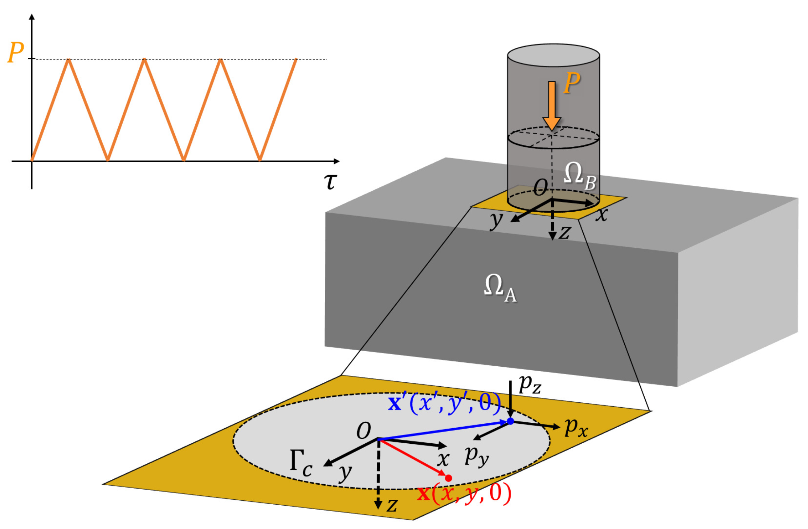
Figure 1. An elastic half-space ( Ω A ) and a cylindrical flat-ended punch ( Ω B ) come into contact under vertical loading and unloading cycles (P).
Lubricants 11 00265 g001
Figure 2. (a) Half-space scheme where surface tractions on a point x Γ c cause subsurface stresses at point x Ω ( α ) ( α = A , B ). (b) A mesh scheme considered for the potential contact zone.
Lubricants 11 00265 g002
Figure 3. (a) Theoretical—continuous blue line—and numerical—square markers—results of the comparison between the theoretical normal contact pressure distribution—continuous line—and the numerical—square markers—for a frictionless contact indentation. (b) Relation between the computed contact stiffness for frictional and for frictionless contact ( k n | μ / k n | frictionless ) as a function of the friction coefficient ( μ ) and the material parameter ( ν ). Moreover, the relation between the contact stiffness for the complete stick and for frictionless contact ( k n | a d h e s i o n / k n | frictionless )—presented by Mossakovskii [99]—is also included.
Lubricants 11 00265 g003
Figure 4. Normal and tangential contact pressure distributions under isotropic frictional contact conditions: μ 1 = μ 2 = μ = { 0.1 , 0.15 , 0.2 , 0.25 , 0.3 , 0.4 } (af), respectively.
Lubricants 11 00265 g004aLubricants 11 00265 g004b
Figure 5. (a) Theoretical von Mises equivalent stress distribution in the half-space—caused by a cylindrical flat-punch indentation—which is normalized by the average pressure ( p o ). (b) Normalized—computed—von Mises equivalent stress in the half-space caused by a cylindrical flat-punch indentation ( μ 1 = μ 2 = μ = 0 ). (cf) Normalized von Mises equivalent stress distributions computed in the elastic half-space under isotropic frictional contact conditions: μ 1 = μ 2 = μ = { 0.1 , 0.2 , 0.3 , 0.4 } , respectively.
Lubricants 11 00265 g005
Figure 6. (a) Computed maximum wear depth evolution as a function of the number of load cycles (N), for several values of the friction coefficient: μ = { 0.1 , 0.2 , 0.4 } . (b) Wear volume evolution with the number of load cycles and different values of the friction coefficient. (ce) Normal contact pressure distributions after 10 3 , 10 4 , and 10 5 load cycles, respectively, and several friction values of the friction coefficient: μ = { 0.1 , 0.2 , 0.4 } .
Lubricants 11 00265 g006
Figure 7. (ac) Computed wear depth distribution after N = 10 5 cycles, for several values of the friction coefficient: μ = { 0.1 , 0.2 , 0.4 } , respectively. (df) Resulting normal contact pressure distribution after N = 10 5 cycles, for μ = { 0.1 , 0.2 , 0.4 } , respectively.
Lubricants 11 00265 g007
Figure 8. von Mises equivalent stress distributions in the half-space after: (a) N = 10 3 cycles and (b) N = 10 5 cycles, for μ = { 0.1 , 0.2 , 0.4 } , respectively. The stress distributions are presented in the x-z-plane.
Lubricants 11 00265 g008
Figure 9. (a) Computed maximum wear depth evolution as a function of the number of load cycles (N), for the following values of the tribological axes’ angle orientation: β = { 0 , 45 , 90 } . (b) Wear volume evolution with the number of load cycles and different values of β .
Lubricants 11 00265 g009
Figure 10. (ac) Computed wear depth distribution after N = 10 5 cycles, for the following values of the tribological axes’ angle orientation: β = { 0 , 45 , 90 } , respectively. (df) Resulting normal contact pressure distribution after N = 10 5 cycles, for β = { 0 , 45 , 90 } , respectively.
Lubricants 11 00265 g010
Figure 11. von Mises equivalent stress distributions in the half-space after: (a) N = 10 3 cycles and (b) N = 10 5 cycles, for β = { 0 , 45 , 90 } , respectively.
Lubricants 11 00265 g011
Disclaimer/Publisher’s Note: The statements, opinions and data contained in all publications are solely those of the individual author(s) and contributor(s) and not of MDPI and/or the editor(s). MDPI and/or the editor(s) disclaim responsibility for any injury to people or property resulting from any ideas, methods, instructions or products referred to in the content.