Article

Lubrication Film Generation with Limited Lubricant Supply and Its Tuned Oil Replenishment in a Cylinder-on-Disc Contact

1
School of Mechanical and Automotive Engineering, Qingdao University of Technology, Qingdao 266520, China
2
Department of Mechanical Engineering, City University of Hong Kong, Kowloon, Hong Kong, China
*
Authors to whom correspondence should be addressed.
Lubricants 2023, 11(3), 93; https://doi.org/10.3390/lubricants11030093
Submission received: 26 December 2022 / Revised: 9 February 2023 / Accepted: 9 February 2023 / Published: 21 February 2023
(This article belongs to the Special Issue State-of-the-Art of Tribology in China)

Abstract

:
Limited lubricant supply (LLS) with tuned dosage is an emerging approach to reduce friction and energy consumption. However, LLS can cause severe starvation when the oil supply is insufficient. Therefore, how to effectively replenish oil to the lubricated contact in LLS operation is very important. Using a custom-made optical slider bearing test rig, this work experimentally revealed some characteristics of LLS lubrication in a cylinder-on-disc contact, and proposed two wettability gradient patterns, namely stripe wettability and interlaced wettability, to regulate the lubricant supply to improve the lubricating properties of LLS. The effect of these two wettability patterns was evaluated experimentally according to the lubricating film thickness. The interferograms of the bearing contact under LLS show that the two patterns can augment the oil replenishment through unidirectional lubricant transport by the unbalanced interfacial force via the wettability gradient. Moreover, the interlaced wettability pattern is more effective due to the discontinuous distribution of lubricant from its hydrophilic/hydrophobic region intervals and the transfer of the hydrophobic film to the hydrophilic regions.

1. Introduction

Lubricated line contacts can be found extensively in many industrial practices. Typical examples include roller bearings, gears, piston ring/cylinder liner systems, and twin-disc contact in tribometers. It is well known that excess lubricant provides no additional benefit to the lubrication of mechanical components. Oil supply is a trade-off between the fully flooded and the severely starved conditions for optimum lubrication performance. In other words, the amount of lubricant used should be limited or intentionally designed to reduce friction and temperature rise. An example can be found in the air–oil lubrication of rolling element bearings [1]. In the meantime, insufficient lubricant supply is a critical issue in line contact tribo-pairs, which typically occurs if there is no efficient intermittent lubricant feeding during machine operation. For example, failures of needle roller bearings [2] in automatic transmissions are reported due to the starvation in the form of uneven oil distribution in the gap between the needle rollers and the inner and outer bearing ring surfaces. For piston ring-cylinder liner contacts, insufficient oil supply is a major cause of scuffing [3]. Gear failures are susceptible to lubricant starvation or loss [4]. Therefore, strategies for oil replenishment to the tribo-pairs using LLS or when starvation occurs need to be explored.
In fact, considerable experimental work has been carried out to understand the lubrication behavior of line contacts under starved conditions. The lubrication behavior of line contacts has been characterized since optical interferometry was first proposed to measure elastohydrodynamic lubrication (EHL) thin films in the 1960s. For example, in the work of Gohar and Cameron [5] and Wedeven et al. [6], transverse film constriction was clearly demonstrated at the roller contact edge. Wymer et al. [7] captured the interferograms of the roller contact end and found that starvation occurred at relatively slow speeds. The film thickness they measured was slightly higher than the theoretical calculation by Wolveridge et al. [8]. In a subsequent study, Dmytrychenko et al. [9] reported the local film thickness as a function of the inlet boundary distance under starvation conditions, with the film shape at the end of the roller becoming more parallel as lubricant starvation increased. Wang et al. [10] explored the unstable starvation phenomenon of line contact EHL at steady speeds. They found that speed and viscosity had obvious effects on instantaneous starvation. In addition to the interferometry measurements of the starved lubrication of line contacts, other experiments were also carried out. Ebner et al. [11] confirmed that a very small amount of initial oil was sufficient for lubrication of EHL line contacts at the FZG twin-disk test rig, although the contact was under starved conditions. They found that the initial oil volume had no marked influence on the coefficient of friction (COF) of polished and axially ground discs. Obert et al. [3] observed the oil distribution by laser-induced fluorescence (LIF) using a newly developed piston ring/cylinder linear model test rig, and they showed that the oil available in the contact gradually decreased over time until scuffing began, and the level of friction coefficient was not significantly affected by the oil supply rate. However, in the study by Michelberger et al. [12], it was shown that the oil supply had a significant effect on COF, which was attributed to different working conditions. Chevalier et al. [13] and Damiens et al. [14] showed theoretically that, for circular point contacts under fully flooded conditions, the oil supply will be fully used to lubricate the contact when the inlet oil layer thickness is less than half of the film thickness. As the inlet oil layer gets higher, only part of the oil supply forms a lubricating film in the contact due to the side flow around the contact. With even a small increase in oil supply, it will approach an asymptotic film thickness (the film thickness under fully flooded conditions). For finite line contacts, there should be similar behavior even they have more side flow resistance, and it may account for the different friction variations with the oil supply [3,11,12].
Many theoretical studies on starved line contacts can also be found in the literature. The effects of starvation and other operation factors, such as thermal effect, non-Newtonian behavior, and surface roughness on lubrication have been extensively investigated. Venner and Hooke [15] carried out numerical calculations to determine the extent of roughness attenuation under starved line contact lubrication. Yang et al. [16] conducted a numerical study on the relation between the inlet meniscus and the lubricant thickness considering thermal and non-Newtonian effects, and their results revealed that in starved contacts, the film temperature rise is lower and traction force is larger than those in fully flooded contacts. Furthermore, there is also a considerable interest in the thermal starved EHL model for gears. Zhu et al. [17] studied the influence of the shape of the inlet oil layer under the same degree of starvation and revealed that a convex profile leads to a higher film thickness in the contact zone. In a study by Liu et al. [18], it was shown that under starvation conditions, the minimum film thickness along the line of action may occur in the region around the highest point of single tooth contact. Sun et al. [19] explored the effect of starved lubrication with increasing slip-to-roll ratios and concluded that an increase in oil supply (inlet layer thickness) beyond its optimum value cannot further improve the lubrication performance of cycloid drives, which is correlated to the results in [13,14]. They also found that the film temperature increases with increasing oil supply, which is consistent with the findings of Yang et al. [16]. Based on a hydrodynamically lubricated line contact, Biboulet et al. [20] analyzed the dependence on the starvation of the load carrying capacity, the friction from Poiseuille flow, and friction from Couette flow, showing that the coefficient of friction for sliding starved conditions is dominated by the Couette term.
The above studies show that insufficient oil supply may increase friction and power loss. Therefore, severe starvation of the contact area must be avoided for effective lubrication performance. On the other hand, if an excessive amount of lubricant is used, it may also result in high power loss, for example due to churning losses, which is unacceptable. Therefore, it is necessary to provide the lubricant in such a way that the tribo-pairs are under LLS conditions so that optimum lubrication behavior with low friction losses can be achieved. For example, the concept of drop-on-demand (DoD) lubrication is proposed to achieve a more favorable method of lubricant supply than the conventional oil dip or injection lubrication. Several studies have been carried out to verify its feasibility in EHL [21,22] and demonstrated that efficient EHL films can be constructed under a certain degree of starvation.
It is not difficult to understand that a key point of LLS lubrication is how to use the supplied oil as much as possible to avoid severe starvation and lubricant waste. In fact, various strategies to prevent oil starvation have been proposed. Typically surface texturing provides an approach in which dimples or grooves are used to facilitate oil storage for enhanced lubrication. For example, Cheong et al. [23] concluded in their experiments using an optical piston ring/cylinder liner contact and fluorescence microscopy that micro-dimples on the liner surface carry oil to the starved outlet, demonstrating a synergetic effect of oil reservoirs and hydrodynamics under reciprocating sliding motion. Using an optical EHL test rig, Galda et al. [24] achieved good tribological performance at low sliding speeds under starved lubrication conditions, and they found that the COF decreased more when dimples were shallow and the area density of oil pockets was small. In their more recent studies, Galda et al. [25] displayed that the film thickness in a steel ball-on-disc contact could be enhanced when the steel ball surface was modified with small average height and small peak height, but with mainly shallow cavities and some valleys of great depth. Another approach is to facilitate the active transport of lubricant to the lubricated area through interfacial forces. Grützmacher et al. [26] proposed a multi-scale texturing approach that can achieve the synergetic effect of friction reduction in the contact and oil migration out of the contact. Liu et al. [27] constructed comb-tooth-shaped grooves on both sides of the bearing track, showing that the geometric gradient of the grooves could enhance oil self-replenishment and increase the film thickness under the LLS. Ge et al. [28] designed a groove structure around the lubricating track on the inner ring surface of a rolling bearing, in which the capillary forces could directly drive the oil to the lubricating region. Different from the surface groove/dimple approach, Li et al. [29] and Liu et al. [30] fabricated a wettability gradient on both sides of the lubricating track by coating a very thin hydrophobic layer. Both studies realized efficient transport and replenishment of lubricants.
The above-mentioned studies show that the smart use of surface wettability can enhance the lubrication performance under LLS conditions. Unfortunately, little work has been carried out to address the oil starvation problem of line contact, which is of high industrial importance. In this paper, two wettability gradient surface patterns, namely, stripe wettability and interlaced wettability, are proposed for better oil replenishment to starved line contacts. Experiments were carried out to see whether these two patterns improved lubricant supply. The results show that both patterns can augment oil replenishment and then achieve lubrication enhancement under LLS, which can contribute to the tribology design of machine elements.

2. Experimental Apparatus and Working Conditions

2.1. Experimental Apparatus

An optical slider-bearing test rig [31], as illustrated in Figure 1a, was used in the present study. The line contact is given by a stationary cylindrical slider (steel) loaded against a rotating disc (BK7 glass). The load is applied directly by calibrated dead weights fixed on the load lever. The alignment of the cylindrical roller is achieved by a parallel mechanism (as shown in Figure 1b). The cylindrical roller has a diameter of 10 mm and a length of 5 mm, while the glass disc has a diameter of 100 mm. The radius of the slider-on-disc contact track is 25 mm, and the speed difference between the ends of the cylindrical slider and the contact center is ±10%. The specified sliding velocity is represented by the velocity at the contact center. The surface of the disc in contact with the cylindrical slider is coated with a Cr layer and a SiO2 layer with a reflectivity of 20% to ensure sharp interferograms and wear resistance. Two laser beams with wavelengths of 655 nm (red light) and 535 nm (green light) were employed as incident lights. According to the dichromatic interference intensity modulation approach [32,33], the film thickness can be obtained with a resolution of 1 nm.
Specimen oils of a given volume were put on the disc using a pipette. The test rig was pre-run for approximately 5 min at a low speed (approximately 1 mm/s) and with a light load (approximately 0.03–0.05 N). For each test at a fixed load and speed, the measurements were repeated five times at each speed, and their average value and standard deviation were calculated. The authors calculated standard deviations to check for measurement uncertainty but did not plot data points in the figures for illustrative purpose. In the experiments, polyalphaolefins (PAOs) were employed as lubricants, and their properties are listed in Table 1. The speed of the disc at the contact center ranged from 27 to 527 mm/s (27.2 mm/s, 44.6 mm/s, 73.1 mm/s, 119.8 mm/s, 196.3 mm/s, 321.7 mm/s, 411.0 mm/s, and 527.0 mm/s). The applied loads were 6 N, 8 N, and 10 N, and the corresponding maximum Hertzian pressures were 54.6 MPa, 63.0 MPa, and 70.5 MPa, respectively. Therefore, the operation is under a hydrodynamic lubrication regime. Lubricant quantities used were 0.5 μL, 1.0 μL, and 2.0 μL. Experiments were carried out under a temperature of 20 ± 2.0 °C and a relative humidity of 25 ± 5%.

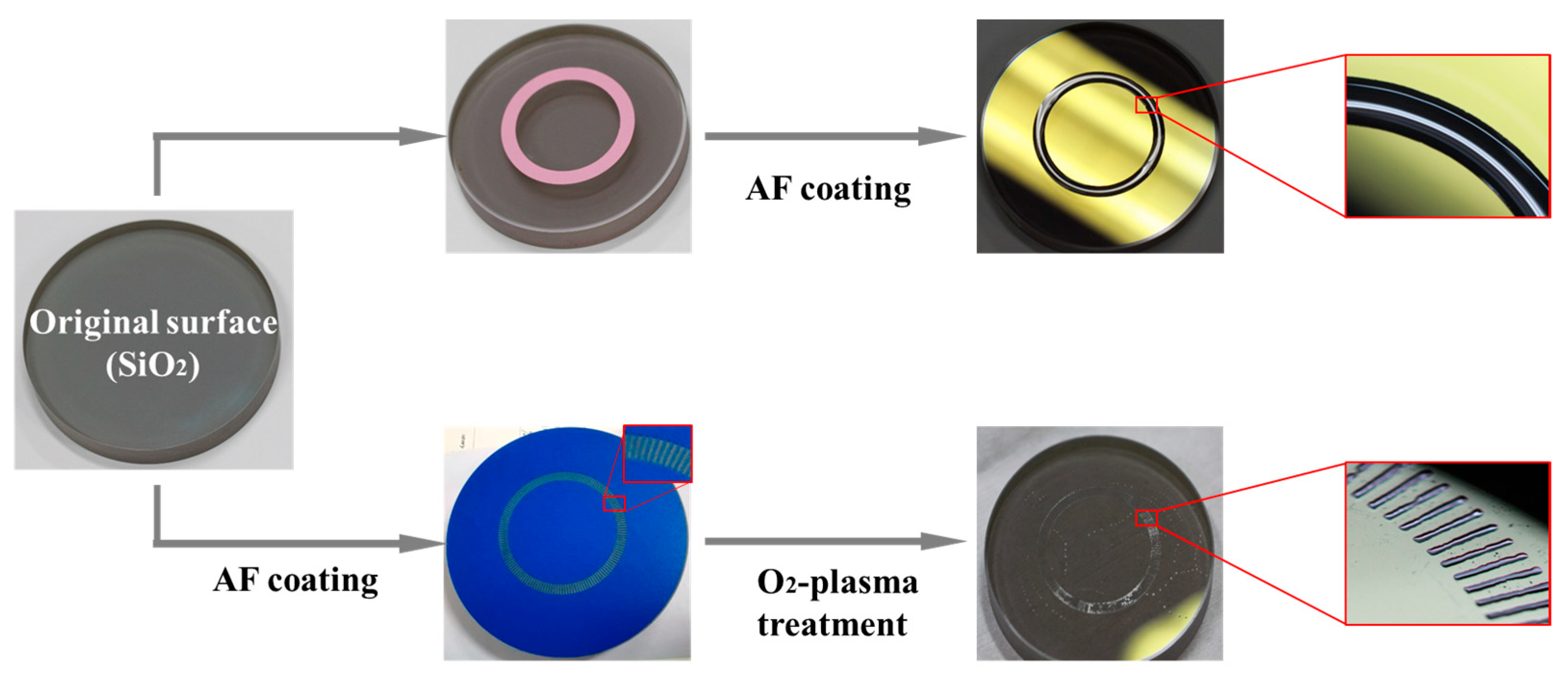
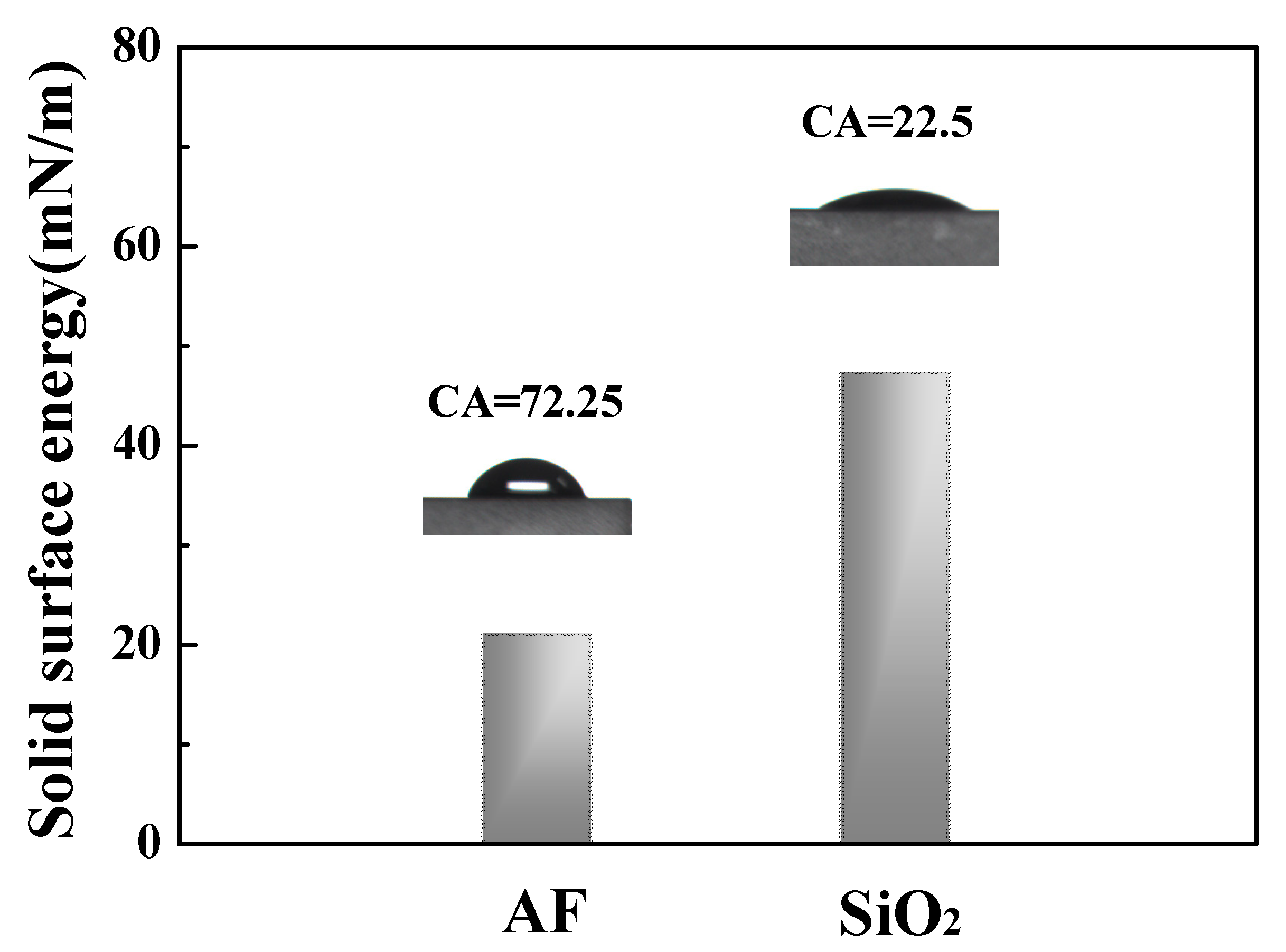
2.2. Disc Surface Modification

Two wettability gradient patterns (see Figure 2), namely stripe wettability and interlaced wettability, are proposed to regulate lubricant supply under LLS. The original disc surface SiO2 is hydrophilic. A commercial anti-fingerprint (abbreviated as AF, 1H,1H,2H,2H-perfluorodecyltrimethoxy-silane) coating (refractive index ≈ 1.33) was used to obtain hydrophobic regions. Patterns of different sizes are obtained through masks, and the detailed process is shown in Figure 3. The AF coating on the disc surface was cured at 80 °C for 30 min. The stripe wettability pattern is prepared in one step with an annular stripe mask covering the disc surface prior to AF coating (see Figure 3). The interlaced wettability patterns were prepared in two steps. In the first step, AF was coated on the entire disc surface, which was then treated by O2 plasma through a mask, thus, producing an interlaced hydrophilic (SiO2)–hydrophobic (AF) zones. From Figure 3, it can be seen that the oil is pinned to the hydrophilic areas. The sizes of the two types of patterns are summarized in Table 2.

3. Results and Discussion

Limited lubricant supply (LLS) indicates the optimal quantity of oil for film lubrication, which reduces the friction and temperature rise induced by large amounts of lubricant or severe starvation. In order to achieve the optimal LLS for line contact, it is necessary to explore the characteristics of lubricating film thickness and approaches to improve oil replenishment, which will be presented in this section.

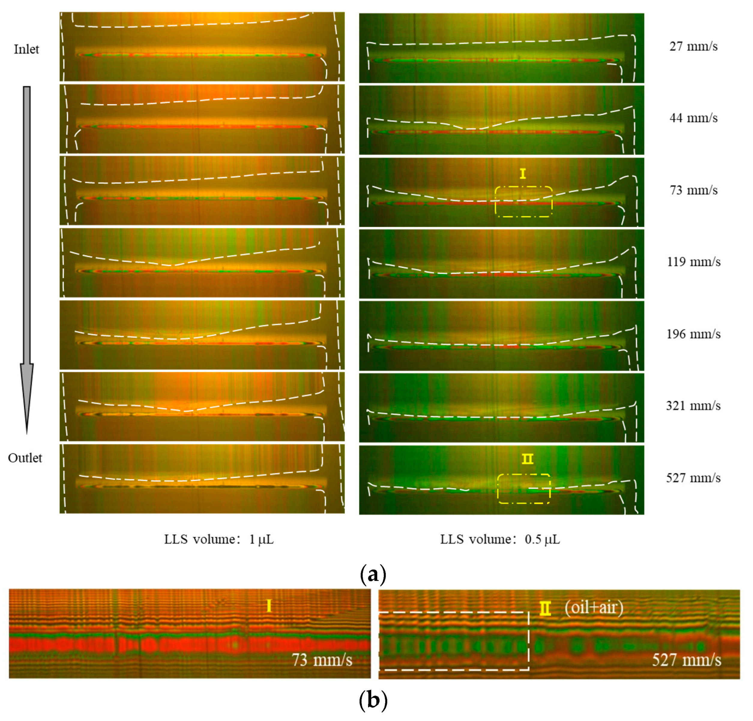
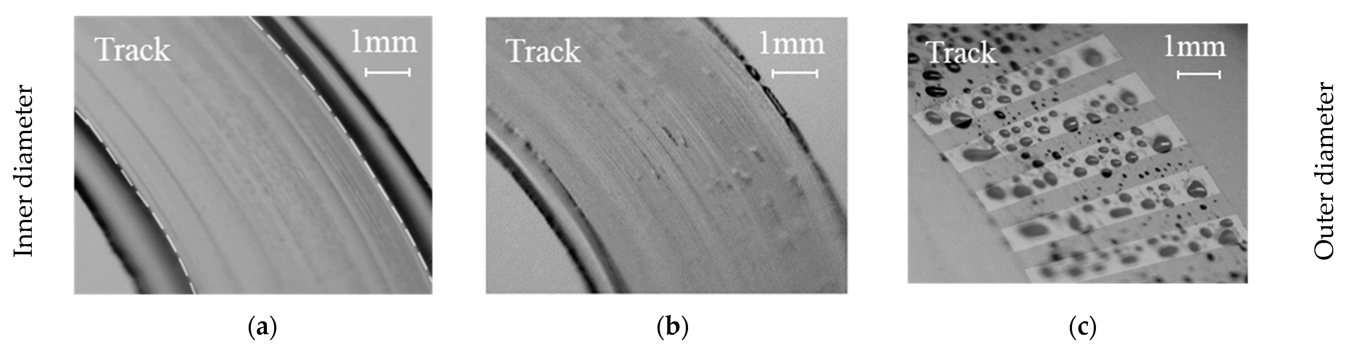
3.1. Lubrication Behaviors of Cylindrical Slider-on-Disc Contact under LLS

Figure 4 illustrates the evolution of the lubrication film in the line contact of the cylindrical slider-on-disc under LLS conditions. A load of 6 N and a sliding speed of 27 to 527 mm/s were applied. Here, PAO20 was used as the lubricant with volumes of 1.0 and 0.5 μL, which theoretically correspond to the average lubricant layer thickness of 1.27 and 0.64 μm, respectively. The annular lubrication track has a radius of 25 mm and a track width of 5 mm. The evolution of typical starvation characteristics for the two oil supply volumes is shown in Figure 4. From Figure 4a, it can be seen that the increase in speed causes the decrease in the oil reservoir, and the air–oil boundary at the inlet reservoir moves to the contact boundary. When the speed is low, the air–oil boundary along the cylindrical slider is almost uniform, indicating that there is no severe oil starvation. However, when the speed increases, the central air–oil boundary of the inlet oil reservoir gets nearer to the contact boundary and leads to severe starvation, while on both sides of the cylindrical slider, only a slight decay of the oil reservoir is observed. Due to the centrifugal force when the speed is higher, more lubricant is pulled to the side of the roller away from the center of the disc, as shown in Figure 4a. In particular, more starvation can be observed for the lubricant volume of 0.5 μL (right column in Figure 4a). At the speed of 73 mm/s, the central air–oil boundary has reached the contact boundary, while for the lubricant volume of 1 μL, it is still some distance away from the contact boundary. The region, where the air–oil boundary reaches the contact boundary, increases with speed. Figure 4b presents enlarged interferograms of regions I and II in Figure 4a. Clearly, in region II, some air–oil stripes occupy the contact gap because no oil reservoir exists at the inlet.
Figure 5 shows the measured central film thickness vs. speed for different oil supply volumes and the fully flooded oil supply. At low speed, the time allowing back-flow is long so that the oil replenishment is satisfactory. Thus, there is not marked difference in central film thickness among all the oil supply volumes. However, as the speed increases, various oil supply volumes give different central film thicknesses, indicating insufficient oil replenishment due to short back-flow time. The results for the fully flooded oil condition present the highest central film thickness, and the smallest oil volume of 0.5 μL provides the lowest central film thickness. Moreover, for the oil volume of 0.5 μL, the central film thickness no longer increases when the speed exceeds 200 mm/s.
To assess the loss of load-carrying capacity when using a limited oil supply, a dimensionless parameter, relative film thickness hRe, is defined as follows:
hRe = hcen/hcen,full
where hcen is the measured central film thickness, and hcen,full is the central film thickness with the fully flooded oil supply. The value of hRe ranges from 0 (film failure) to 1 (fully flooded). Figure 5b presents hRe as a function of speed. It is obvious that the higher the speed, the greater the loss of load-carrying capacity, which is due to the incomplete oil replenishment with the short oil back-flow time. As the speed increases, the hRe of 1.0 and 2 μL supply volumes does not decrease much after 321.74 mm/s, while the hRe of 0.5 μL continues to decline.
On the original disc surface, the oil replenishment is mainly driven by the surface tension of the lubricant. As the lubricant approaches the roller, most of the lubricant is diverted to the end sides of the roller, forming two side ridges. At increased speeds, the oil in the side ridges cannot fully flow back to the lubrication track between two consecutive slide-overs.
Figure 6 shows the effect of load on hcen vs. speed for fully flooded conditions (solid lines) and the LLS of 1 μL oil volume. Figure 6a shows that hcen decreases with increasing load under both oil supply conditions. Figure 6b plots hRe vs. speed for three different loads. The hRe for different loads remains almost constant at first and then decreases significantly when the speed exceeds 200 mm/s. In addition, hRe is larger for heavier loads, indicating that the degree of starvation becomes relatively weak with increasing loads. Furthermore, light loads present more load-carrying losses than heavy loads under LLS. Under the present experimental conditions, the contact is in the hydrodynamic lubrication regime, where the film thickness depends largely on loads. For the same oil supply or the same supply oil thickness on the lubrication track, heavy loads present low film thickness and, therefore, less starvation.
To clarify the effect of viscosity, three PAO oils (PAO4, PAO8, and PAO20) were employed in the experiments, as shown in Figure 7a, to obtain the curves of film thickness vs. speed. For both fully flooded lubricant supply and an LLS of 0.5 μL supply oil volume, the film thickness increases with viscosity. However, under LLS, it is noted that the film thickness increasing rates with speed are different for the three PAOs. Indeed, PAO4 presents the largest increasing rate due to its low viscosity and, thus, less oil replenishment (flow back) resistance. At the largest speed of 527 mm/s, the film thickness of PAO4 has caught up with that of PAO8. Similarly, the hRe of PAO4, which does not change much with speed, is higher than that of PAO8 and PAO20. On the other hand, the hRe of PAO20 decreases sharply with increasing speed, indicating more load-carrying capacity loss.

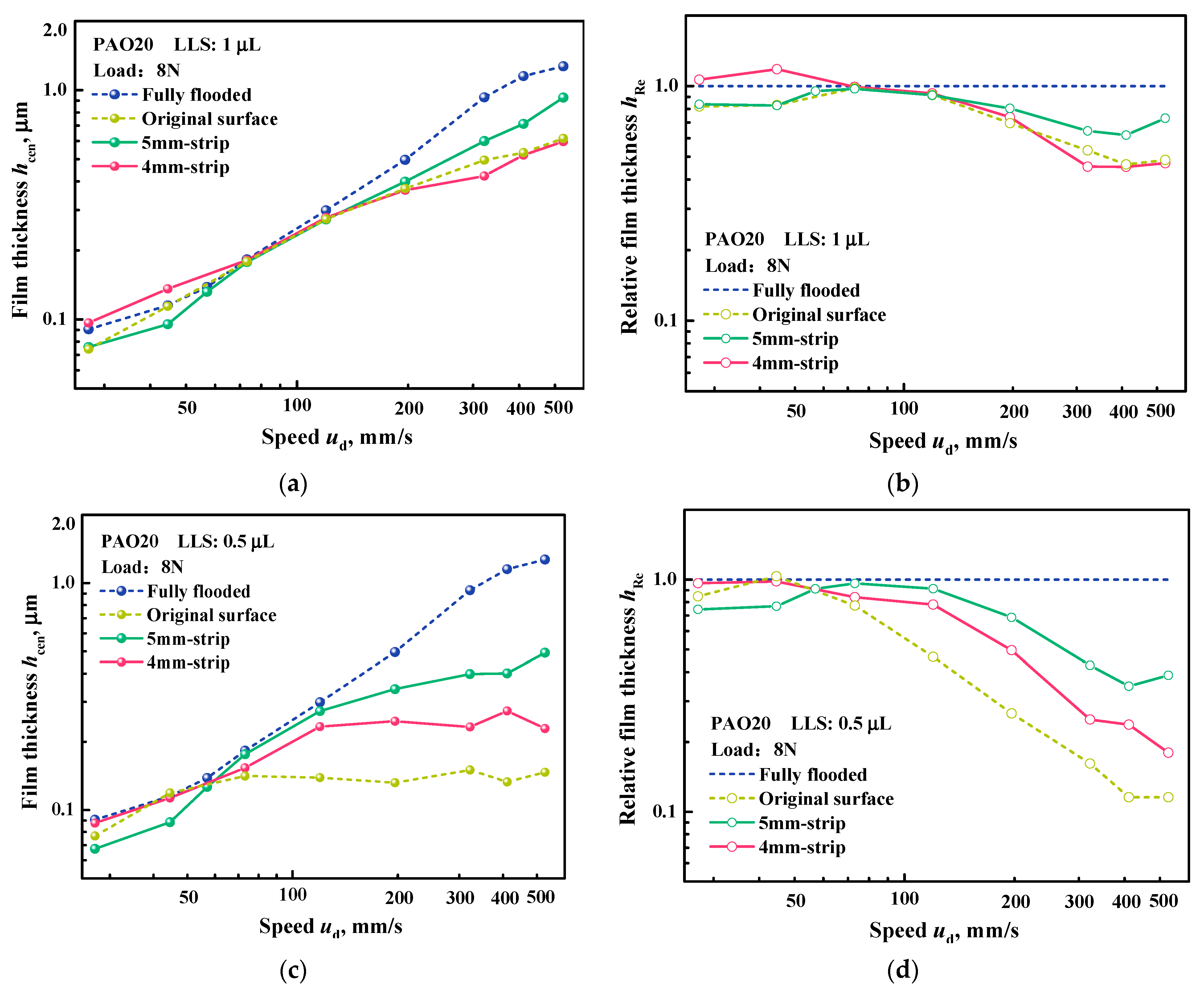
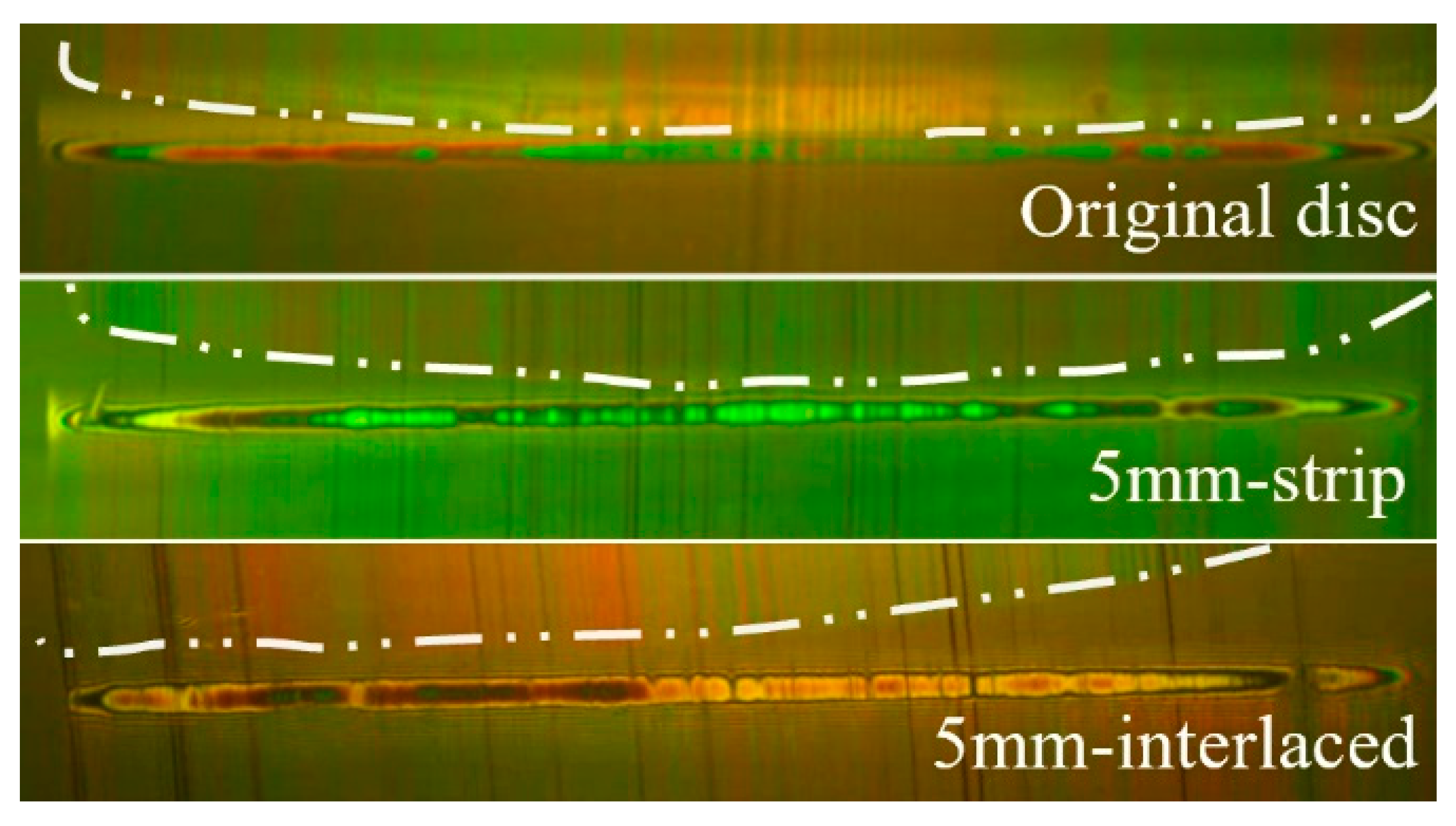
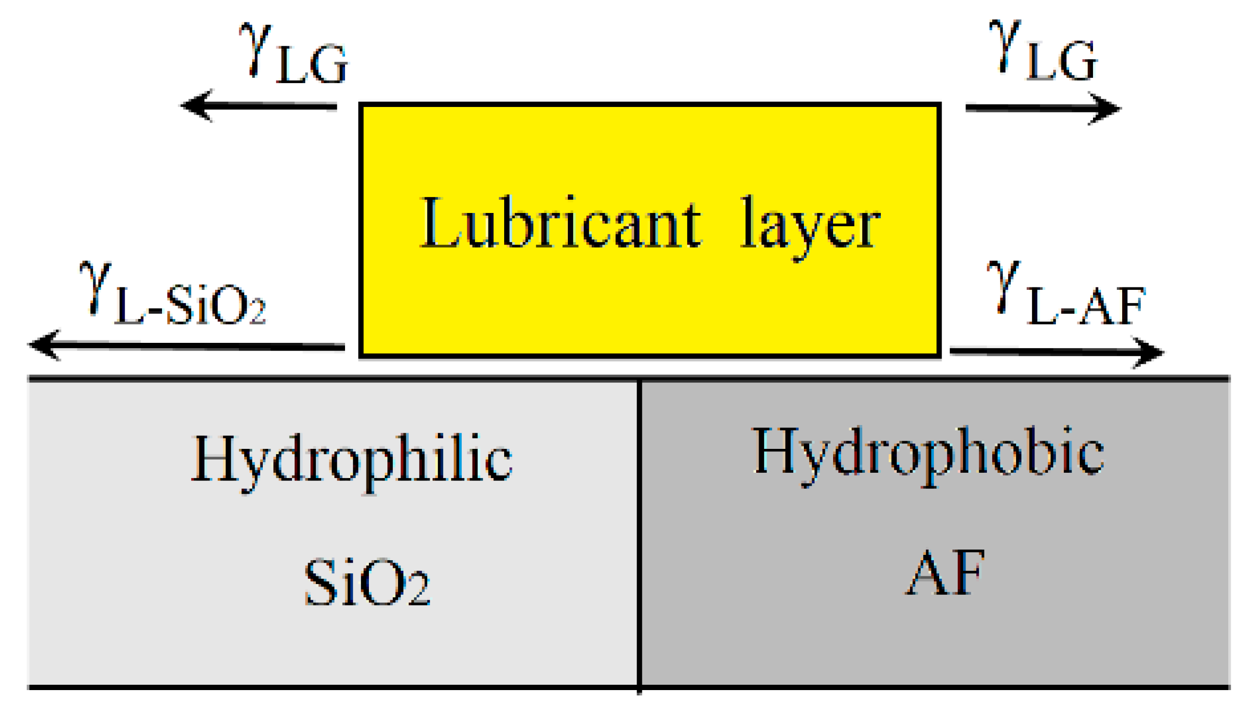
3.2. Wettability Gradient Patterns and Enhanced Film Thickness

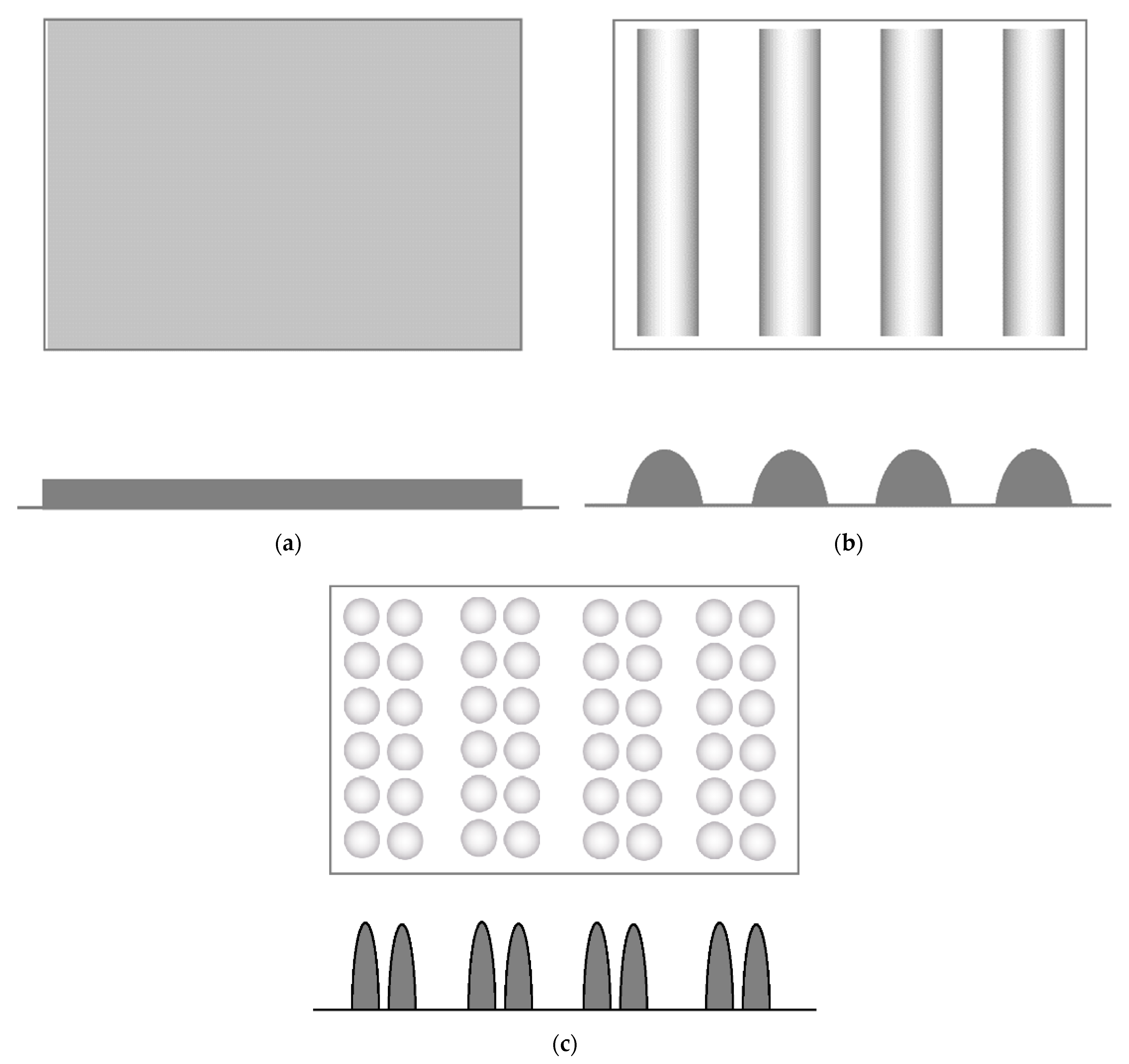
3.2.1. Stripe Wettability Pattern

The 5 mm-wide and 4 mm-wide stripe wettability patterns (denoted as 4 mm-stripe wettability and 5 mm-stripe wettability) were first prepared for trapping oil in the annular lubrication track by wettability gradient [25,26]. Figure 8 shows how hcen and hRe vary as a function of sliding speeds for the original surface, the 5 mm-stripe wettability surface, and the 4 mm-stripe wettability surface. Two LLS volumes, 0.5 μL and 1 μL, were used. It can be directly seen that at high speeds (>100~200 mm/s), the film thickness with the 5 mm-stripe wettability is higher than that with both the 4 mm-stripe wettability and the original surface under LLS volumes of 0.5 μL and 1 μL, respectively. Furthermore, from the hRe depicted in Figure 8b,d, it is clear that the 5 mm-stripe wettability can enhance load-carrying capacity more than the 4 mm-stripe wettability under LLS. Obviously, the present study demonstrates that the stripe wettability pattern is an effective way to trap lubricant on the track.
Figure 9 shows the interferograms of the original disc, the 4 mm-stripe wettability pattern and the 5 mm-stripe wettability pattern at the speed of 527 mm/s with a 1 μL and 0.5 μL oil supply. The inlet oil reservoir is correlated with hcen, as shown in Figure 8a,c. For the 1 μL oil supply, the 4 mm-strip wettability surface provides an inlet oil reservoir similar to the original disc surface, especially in the central contact area. Therefore, the 4 mm wettability does not significantly increase the load-carrying capacity. However, the air–oil boundary of the inlet reservoir for the 5 mm-strip wettability is different. For the oil volume of 1 μL, the 5 mm-strip wettability presents more inlet oil reservoirs in the middle and, thus, a higher film thickness than the 4 mm-strip wettability. Moreover, for the 5 mm-strip wettability surface, there is uniform oil distribution along the length of the roller.

3.2.2. Interlaced Wettability Pattern

Generally, the oil does not necessarily remain on the lubrication track in the form of a uniform layer. Sometimes they are discontinuously distributed due to non-uniform interfacial properties, such as droplets or discontinuous oil patches. It was recently shown that discontinuous oil distribution on the lubrication track can improve oil supply and enhance load-carrying capacity under LLS [30] due to oil dewetting as the result of the low surface energy of bounding surfaces. Therefore, it is reasonable to prepare the lubrication track in such a way that oil can stays in a discrete form. In this work, an interlaced wettability pattern, as shown in Figure 2, was fabricated, and its influence on the lubrication behavior of cylindrical slider-on-disc contacts was investigated in this section.
The interlaced wettability pattern with a width of 5 mm (denoted as 5 mm-interlaced wettability) was prepared, which is capable of trapping the lubricant in the hydrophilic rectangular stripe region through wettability differences. Figure 3 shows that on the lubrication track, the lubricant has a distribution of evenly spaced stripes. Figure 10 presents the variation of hcen and hRe with 5 mm-interlaced wettability for two LLS volumes of 0.5 μL and 1 μL. In Figure 10a,b, where the LLS volume is 1 μL, the film thickness of 5 mm-interlaced wettability is higher than that of the original surface when the speed exceeds 100 mm/s and is slightly lower than that of fully flooded oil supply. For the LLS volume of 0.5 μL, as shown in Figure 10c,d, when the speed exceeds 80 mm/s, the film thickness with 5 mm-interlaced wettability is significantly lower than that of fully flooded oil supply, but higher than that of the original surface.
Figure 11 depicts the interferograms of the original disc and the 5 mm-interlace wettability pattern with a 1 μL and 0.5 μL oil supply at speeds of 196 mm/s and 527 mm/s. The inlet oil reservoir with 5 mm-interlaced wettability is generally larger than that of the original disc, which indicates that the film thickness with the 5 mm-interlaced wettability is higher. Figure 11 also shows that the LLS of 0.5 μL produces a larger inlet oil reservoir with the 5 mm-interlaced wettability at the same speed compared to the LLS of 1 μL. Thus, the LLS of 0.5 μL produces higher oil film thickness than the LLS of 1 μL. For example, in Figure 10, when the LLS is 0.5 μL, the central film thickness increases from 0.15 μm to 0.61 μm (by 300.6%) at 527 mm/s, while when the LLS is 1 μL, the film thickness at the same speed only increases from 0.62 μm to 1.1 μm (by 77.4%). The interlaced wettability works more effectively for oil replenishment when under severe starvation or LLS.
When the stripe wettability pattern is employed, it presents a wettability gradient along both sides of the lubrication track, which plays an important role in the oil replenishment. From Figure 2, it can be seen that the interlaced wettability pattern can be equivalently obtained by periodically removing some hydrophilic rectangular areas in the stripe wettability pattern. Interestingly, although the interlaced wettability pattern is part of the stripe wettability pattern, it gives higher film thickness than the stripe wettability pattern when the speed is high. Figure 12 presents some data for the disc speed of 411 mm/s. When the LLS volume of 0.5 μL was applied, the central film thickness increased by 25% from the stripe wettability pattern to the interlaced wettability pattern, compared with a 31.0% increase with the LLS of 1 μL.
Figure 13 shows the interferograms of Figure 12b with the 5 mm-stripe wettability pattern, the 5 mm-interlaced wettability pattern, and the original disc. It can be seen that the captured interferograms of the three surfaces are correlated with the central film thickness in Figure 12b. Obviously, the 5 mm-interlaced wettability pattern presents more oil supply at the central inlet region than the 5 mm-stripe wettability pattern and the original disc. The 5 mm-strip wettability pattern provides a concave oil reservoir along the contact boundary, with some oil supply remaining at the central contact edge. The original disc also gives a concave oil reservoir, but there is no oil reservoir at the central boundary of contact, which leads to a much lower central film thickness.
For stripe wettability patterns, it is demonstrated [28,29] that the wettability gradient can induce liquid transport from hydrophobic to hydrophilic regions and promote oil replenishment. In the present study, a low energy surface (created with AF coating) and high energy surface (a glass surface, SiO2), as shown in Figure 14, generate an unbalanced interfacial force to enhance replenishment for the lubrication of the cylindrical slider. With the interlaced wettability pattern, lubricant distribution may be more favorable for load-carrying capacity. One would be interested in how it works.
In the experiments, there were interesting observations of the oil distribution under LLS conditions. For the original surface (SiO2), the lubricant is in the form of a continuous thin layer as it leaves the central contact and stays on the lubrication track. On the other hand, some lubricant is diverted by the cylindrical slider, forming two side ridges. In general, not all the lubricant in the side ridge can flow back to the lubrication track, as shown in Figure 15a. This is also applied to the case of the stripe wettability pattern, as shown in Figure 15b. However, the side ridges with the stripe wettability surface are smaller, which can be attributed to the unidirectional lubricant flow driven by an unbalanced surface force induced by the wettability gradient. The unbalanced surface force exerted on the lubricant layer located on the boundary of the AF area (hydrophobic) and the SiO2 area (hydrophilic) is schematically shown in Figure 16. On the top of the lubricant layer, the lubricant is subjected to the same amount of surface tension γLG on both sides. However, at the bottom, the interfacial force γL-SiO2 is greater than γL-AF since the surface energy of SiO2 is greater than that of AF. Therefore, it is indisputable that some lubricant in the two side ridges can be driven to the lubrication track, indicating that more lubricant is supplied to the contact. For the interlaced wettability surface, as shown in Figure 15c, the lubricant redistributed in the form of droplets mainly on the hydrophilic patches, and no side ridge was found. Furthermore, it is noted that the oil distribution on the interlaced wettability surface in Figure 15c is quite different from that in Figure 3. In Figure 3, the oil remains on the hydrophilic patch in the form of a continuous thin layer, which is also a result of the unbalanced interfacial force. However, during the experiments, the lubricant was found to stay mainly on the hydrophilic patches, but in the form of discrete droplets. The difference between the oil distribution before and after the experiment may be attributed to the change in the surface energy of the hydrophilic patches. In the experiments, the interlaced wettability surfaces were rubbed against the lubricant film, and it is postulated that some of the AF film could be transferred to the adjacent hydrophilic patches. Therefore, their surface energy is reduced. Consequently, dewetting occurs to present oil droplets.
Figure 17 shows a simple geometric description of oil distributions for the stripe wettability and the interlaced wettability patterned surfaces before and after testing in this study. Figure 17a depicts a uniform oil layer on the prescribed lubrication region, which is the stripe wettability pattern. In Figure 6b, the oil appears in the form of equidistant rectangular patches, which is from the interlaced wettability, and the thickness of the patch layer is larger than that of the uniform oil layer (the same oil volume supplied). The AF film transfer from hydrophobic to hydrophilic regions may occur in such a way that dewetting takes place on the original hydrophilic region, as illustrated in Figure 17c, where the droplets are higher than the oil rectangular patch because they are discretized from the oil patches. Another explanation for the droplet generation is that the AF film transfer generates heterogenous wettability on the original hydrophilic region with hydrophobic subregions, and the oil is pinned to the hydrophilic areas in the form of droplets.
Recently, the authors numerically showed that oil supply in the form of droplets can build lubricating film more effectively than that of a uniform oil layer [34], which is attributed to the film pressure generated early when the oil droplets enter the bearing contact. The advantage of the 5 mm-interlaced wettability over the 5 mm-stripe wettability of the film building can be explained as shown in Figure 18. It can be seen from Figure 18a that for the same oil supply, the discrete oil droplets (II) which initially evolved from the uniform layer (I) are higher, and that they encounter the bounding surfaces earlier (at point B) than the uniform layer (at point A). In fact, at the entrance, discrete droplets can merge, and a continuous oil reservoir is observed [34]. Figure 18b shows that oil droplets fill the contact entrance gap more that uniform oil layer and provide a larger load-bearing area and induces a higher film thickness. Indeed, the non-continuous redistribution of the lubricant layer in Figure 18 is realized in two steps. The first is the active generation of spaced rectangular patches through the interlaced wettability. The second is the droplet formation from the oil patch layers by AF transfer to the hydrophilic areas.

4. Conclusions

In this paper, the oil film building performance and the effect of wettability gradient in a cylinder-on-glass disc sliding contact with LLS were investigated experimentally, and the results can be summarized as follows:
(1) Under LLS, captured interferograms show that when the speed is low, the oil reservoir presents a uniform distribution along the contact boundary, and then as the speed increases, the air–oil boundary of the oil reservoir first reaches the central boundary of the contact and becomes concave. The central film thickness decreases as the oil supply decreases. A dimensionless parameter hRe is defined to assess the LLS load-carrying capacity relative to that under fully flooded conditions. It is demonstrated that high speeds and low loads lead to more loss of load-carrying capacity.
(2) A stripe wettability pattern is proposed to generate unidirectional interfacial forces to improve lubricant replenishment. Clear evidence is obtained that the stripe wettability pattern can reduce the size of the side ridges. It is demonstrated that a stripe wettability pattern with a width equal to the lubrication track width can provide better performance than that with a width smaller than the track width.
(3) An interlaced wettability pattern is proposed to improve lubricant supply. On the interlaced wettability surface, the lubricant redistributes in the form of droplets mainly on the hydrophilic patches, which is attributed to the unbalanced interfacial force between the hydrophilic patch and its hydrophobic surrounding, and some AF film transfer during running. It is shown that the interlaced wettability pattern can provide higher film thickness than the stripe wettability pattern. The mechanism by which the interlaced wettability pattern enhances the lubricating film is that the discrete oil droplets fill the lubricated surface gap earlier, and, therefore, the oil droplets provide a larger load-bearing area and induces a higher film thickness.

Author Contributions

Conceptualization, F.G., P.L.W. and W.J.; methodology, W.J. and F.G.; validation, W.J.; formal analysis, W.J., S.L. and Z.J.; investigation, W.J., F.G. and P.L.W.; resources, W.J.; data curation, W.J. and Z.J.; writing—original draft preparation, W.J.; writing—review and editing, F.G. and P.L.W.; visualization, F.G. and P.L.W.; supervision, F.G. and P.L.W.; project administration, F.G.; funding acquisition, F.G. and P.L.W. All authors have read and agreed to the published version of the manuscript.

Funding

This research was funded by the Research Grants Council of Hong Kong, project number CityU11216619, and the National Natural Science Foundation of China, grant number 52175173/52005278.

Data Availability Statement

The data presented in this study are available on request from the corresponding author.

Conflicts of Interest

The authors declare no conflict of interest.

References

  1. Lubrication of Rolling Bearings. Available online: www.schaeffler.com/remotemedien/media/_shared_media/08_media_library/01_publications/schaeffler_2/tpi/downloads_8/tpi_176_de_en.pdf (accessed on 10 December 2022).
  2. Raju, K.S.; Veettil, M.P.; Ray, S.; Shi, F. Needle Roller Bearing Lubricant Flow CFD Simulations. SAE Tech. Pap. Ser. 2013, 26, 41. [Google Scholar] [CrossRef]
  3. Obert, P.; Füßer, H.-J.; Bartel, D. Oil distribution and oil film thickness within the piston ring-liner contact measured by laser-induced fluorescence in a reciprocating model test under starved lubrication conditions. Tribol. Int. 2019, 129, 191–201. [Google Scholar] [CrossRef]
  4. Riggs, M.R.; Murthy, N.K.; Berkebile, S.P.; Korenyi-Both, A.L. Scuffing Resistance and Starved Lubrication Behavior in Helicopter Gear Steels Coated with Nanocomposite Surface Coatings with and without a Hard Sublayer. Tribol. Trans. 2020, 63, 610–620. [Google Scholar] [CrossRef]
  5. Gohar, R.; Cameron, A. The Mapping of Elastohydrodynamic Contacts. ASLE Trans. 1967, 10, 215–225. [Google Scholar] [CrossRef]
  6. Wedeven, L.D.; Evans, D.; Cameron, A. Optical Analysis of Ball Bearing Starvation. J. Lubr. Technol. 1971, 93, 349–361. [Google Scholar] [CrossRef] [Green Version]
  7. Wymer, D.G.; Cameron, A. Elastohydrodynamic lubrication of a line contact. Proc. Inst. Mech. Eng. 1974, 188, 221–238. [Google Scholar] [CrossRef]
  8. Wolveridge, P.E.; Baglin, K.P.; Archard, J.F. The starved lubrication of cylinders in line contact. Proc. Inst. Mech. Eng. 1970, 185, 1159–1169. [Google Scholar] [CrossRef]
  9. Dmytrychenko, N.; Aksyonov, A.; Gohar, R.; Wan, G. Elastohydrodynamic lubrication of line contacts. Wear 1991, 150, 303–313. [Google Scholar] [CrossRef]
  10. Wang, Z.; Shen, X.; Chen, X.; Han, Q.; Shi, L. Experimental study of starvation in grease-lubricated finite line contacts. Ind. Lubr. Tribol. 2017, 69, 963–969. [Google Scholar] [CrossRef]
  11. Ebner, M.; Yilmaz, M.; Lohner, T.; Michaelis, K.; Höhn, B.R.; Stahl, K. On the effect of starved lubrication on elasto-hydrodynamic (EHL) line contacts. Tribol. Int. 2018, 118, 515–523. [Google Scholar] [CrossRef]
  12. Michelberger, B.; Jaitner, D.; Hagel, A.; Striemann, P.; Kröger, B.; Wetzel, F.-J.; Leson, A.; Lasagni, A.F. Friction Response of Piston Rings for Application-like Starvation and Benefit of Amorphous Carbon Coatings. Coatings 2022, 12, 738. [Google Scholar] [CrossRef]
  13. Chevalier, F.; Lubrecht, A.A.; Cann, P.M.E.; Colin, F.; Dalmaz, G. Film Thickness in Starved EHL Point Contacts. J. Tribol. 1998, 120, 126–133. [Google Scholar] [CrossRef]
  14. Damiens, B.; Venner, C.H.; Cann, P.M.E.; Lubrecht, A.A. Starved Lubrication of Elliptical EHD Contacts. J. Tribol. 2004, 126, 105–111. [Google Scholar] [CrossRef]
  15. Venner, C.H.; Hooke, C.J. Surface roughness attenuation in ehl line and point contacts under conditions of starved lubrication. In Proceedings of the IUTAM Symposium on Elastohydrodynamics and Micro-Elastohydrodynamics, Cardiff, UK, 1–3 September 2004; pp. 59–70. [Google Scholar]
  16. Yang, P.; Wang, J.; Kaneta, M. Thermal and Non-Newtonian Numerical Analyses for Starved EHL Line Contacts. J. Tribol. 2006, 128, 282–290. [Google Scholar] [CrossRef] [Green Version]
  17. Zhu, C.; Sun, Z.; Liu, H.; Song, C.; Li, Z.; Wang, Z. Effect of the shape of inlet oil-supply layer on starved lubrication performance of a cycloid drive. In Proceedings of the International Design Engineering Technical Conferences and Computers and Information in Engineering Conference, BSN, MT, USA, 2–5 August 2015. 57205: V010T11A049. [Google Scholar]
  18. Liu, H.; Zhu, C.; Sun, Z.; Song, C. Starved lubrication of a spur gear pair. Tribol. Int. 2016, 94, 52–60. [Google Scholar] [CrossRef]
  19. Sun, Z.; Zhu, C.; Liu, H.; Song, C.; Gu, Z. Study on Starved Lubrication Performance of a Cycloid Drive. Tribol. Trans. 2016, 59, 1005–1015. [Google Scholar] [CrossRef]
  20. Biboulet, N.; Colin, F.; Lubrecht, A. Friction in starved hydrodynamically lubricated line contacts. Tribol. Int. 2012, 58, 1–6. [Google Scholar] [CrossRef]
  21. van der Kruk, W.M.; Smit, S.A.; Segers, T.J.; Li, X.M.; Venner, C.H. Drop-on-Demand Printing as Novel Method of Oil Supply in Elastohydrodynamic Lubrication. Tribol. Lett. 2019, 67, 1–12. [Google Scholar] [CrossRef] [Green Version]
  22. Mirza, M.; Yilmaz, M.; Thieme, E.; Lohner, T.; Venner, C.H. Drop-On-Demand Lubrication of Gears: A Feasibility Study. Front. Mech. Eng. 2021, 7, 746406. [Google Scholar] [CrossRef]
  23. Cheong, J.; Wigger, S.; Füßer, H.J.; Kaiser, S.A. The oil film around a cylindrical micropore in a sliding contact visualized by fluorescence microscopy on a tribometer. Tribol. Int. 2022, 165, 107309. [Google Scholar] [CrossRef]
  24. Galda, L.; Sep, J.; Prucnal, S. The effect of dimples geometry in the sliding surface on the tribological properties under starved lubrication conditions. Tribol. Int. 2016, 99, 77–84. [Google Scholar] [CrossRef]
  25. Galda, L.; Sep, J.; Swirad, S. Effect of the Sliding Element Surface Topography on the Oil Film Thickness in EHD Lubrication in Non-Conformal Contact. Materials 2022, 15, 7549. [Google Scholar] [CrossRef]
  26. Grützmacher, P.G.; Rosenkranz, A.; Szurdak, A.; Grüber, M.; Gachot, C.; Hirt, G.; Mücklich, F. Multi-scale surface patterning—An approach to control friction and lubricant migration in lubricated systems. Ind. Lubr. Tribol. 2019, 71, 1007–1016. [Google Scholar] [CrossRef]
  27. Liu, C.; Guo, F.; Wong, P.L.; Li, X. Laser pattern-induced unidirectional lubricant flow for lubrication track replenishment. Friction 2022, 10, 1234–1244. [Google Scholar] [CrossRef]
  28. Ge, L.; Wang, C.; Yan, K.; Zhu, Y.; Hong, J. Design of groove structures for bearing lubrication enhancement based on the flow mechanism analysis. Tribol. Int. 2021, 158, 106950. [Google Scholar] [CrossRef]
  29. Li, X.; Guo, F.; Wong, P.; Zhao, Y. Regulation of lubricant supply by wettability gradient in rolling EHL contacts. Tribol. Int. 2018, 120, 565–574. [Google Scholar] [CrossRef]
  30. Liu, C.; Guo, F.; Wong, P.; Li, X. Tribological behaviour of surfaces with stepped wettability under limited lubricant supply. Tribol. Int. 2020, 141, 105880. [Google Scholar] [CrossRef]
  31. Guo, F.; Wong, P.L.; Fu, Z.; Ma, C. Interferometry Measurement of Lubricating Films in Slider-On-Disc Contacts. Tribol. Lett. 2010, 39, 71–79. [Google Scholar] [CrossRef]
  32. Liu, H.C.; Guo, F.; Guo, L.; Wong, P.L. A Dichromatic Interference Intensity Modulation Approach to Measurement of Lubricating Film Thickness. Tribol. Lett. 2015, 58, 1–11. [Google Scholar] [CrossRef]
  33. Guo, F.; Wong, P. A multi-beam intensity-based approach for lubricant film measurements in non-conformal contacts. Proc. Inst. Mech. Eng. Part J J. Eng. Tribol. 2002, 216, 281–291. [Google Scholar] [CrossRef]
  34. Li, S.; Guo, F.; Wong, P.L.; Li, X. Numerical analysis of lubrication of conformal contact with discontinuous oil drop-lets. Tribol. Int. 2022, 173, 107632. [Google Scholar]
Figure 1. Optical cylindrical slider-bearing test rig. (a) Schematic of the test rig; (b) slider alignment unit, as follows: (1) adjustment bolts, (2) loading lever, and (3) holder and cylindrical slider.
Lubricants 11 00093 g001
Figure 2. Schematic of wettability patterns manufactured on the discs.
Lubricants 11 00093 g002
Figure 3. Scheme of surface modification and distribution of oil on the track.
Lubricants 11 00093 g003
Figure 4. Lubrication in cylindrical slider-on-disc contact, load = 6 N, PAO20, oil supply volume of 1 μL and 0.5 μL. (a) Interferograms of starvation evolution with increasing speeds; (b) enlarged interferograms of areas I and II (the white dashed line is the boundary of the air–oil meniscus, and the center of the disc is on the right side of each image).
Lubricants 11 00093 g004
Figure 5. Film thickness vs. speed in cylindrical slider-on-disc contact, load = 6 N, PAO20, oil supply volume of 2 μL, 1 μL, and 0.5 μL. (a) hcen vs. ud; (b) hRe vs. ud.
Lubricants 11 00093 g005
Figure 6. Film thickness vs. speed in cylindrical slider-on-disc contact, oil supply volume of 1 μL, load = 6 N, 8 N, and 10 N, PAO20. (a) hcen vs. ud; (b) hRe vs. ud.
Lubricants 11 00093 g006
Figure 7. Central film thickness vs. speed in cylindrical slider-on-disc contact, load = 6 N, oil supply volume of 0.5 μL, PAO4, PAO8, and PAO20. (a) hcen vs. ud; (b) hRe vs. ud.
Lubricants 11 00093 g007
Figure 8. Influence of stripe wettability on the film thickness, load = 8 N. (a) hcen vs. ud, oil supply volume of 1 μL; (b) hRe vs. ud, oil supply volume of 1 μL; (c) hcen vs. ud, oil supply volume of 0.5 μL; and (d) hRe vs. ud, oil supply volume of 0.5 μL.
Lubricants 11 00093 g008
Figure 9. Interferograms of stripe wettability at different speeds, load = 8 N, oil supply volumes of 1 μL and 0.5 μL.
Lubricants 11 00093 g009
Figure 10. Influence of interlaced wettability patterns on hcen and hRe, PAO20, load = 8 N. (a) hcen vs. ud, oil supply volume of 1 μL; (b) hRe vs. ud, oil supply volume of 1 μL; (c) hcen vs. ud, oil supply volume of 0.5 μL; and (d) hRe vs. ud, oil supply volume of 0.5 μL.
Lubricants 11 00093 g010aLubricants 11 00093 g010b
Figure 11. Interferograms of oil films under 5 mm-interlaced wettability patterns at different speeds, PAO20, load = 8 N, oil supply volume of 1 μL and 0.5 μL.
Lubricants 11 00093 g011
Figure 12. The central film thickness with different surface wettability, PAO20, disc speed = 411 mm/s, load = 8 N. (a) Oil supply volume of 0.5 μm; (b) oil supply volume of 1.0 μm.
Lubricants 11 00093 g012
Figure 13. Inlet oil reservoir with different modified surface, load = 8 N, oil supply volume of 0.5 μL, disc speed = 411 mm/s.
Lubricants 11 00093 g013
Figure 14. Contact angle (CA) with PAO20 on the AF and SiO2 surfaces.
Lubricants 11 00093 g014
Figure 15. Lubricant distribution on the track after rolling under LLS volume = 2 μL. (a) Original surface; (b) 5 mm-stripe wettability; (c) 5 mm-interlaced wettability.
Lubricants 11 00093 g015
Figure 16. Unbalanced interface force induced by the wettability gradient.
Lubricants 11 00093 g016
Figure 17. Schematic of oil distributions for the same LLS quantity. (a) Uniform layer; (b) discrete patches; (c) discrete droplets.
Lubricants 11 00093 g017
Figure 18. Film pressure building for uniform oil layer and discrete oil droplet distribution. (a) Geometry of the uniform oil layer and the discrete oil droplet; (b) schematic illustration of pressure generation.
Lubricants 11 00093 g018
Table 1. Properties of lubricants.
LubricantsDynamic Viscosity/(mPa·s@20 °C)Refractive Index
PAO20379.951.48
PAO8109.51.47
PAO430.71.49
Table 2. Sizes of the stripe wettability pattern and the interlaced wettability pattern.
Stripe WettabilityInterlaced Wettability
Pattern typeLubricants 11 00093 i001Lubricants 11 00093 i002
Central radius, Rc (mm)25
Track width, W (mm)4, 55
Width of wettability-interlaced
B = L (mm)
0.5
Disclaimer/Publisher’s Note: The statements, opinions and data contained in all publications are solely those of the individual author(s) and contributor(s) and not of MDPI and/or the editor(s). MDPI and/or the editor(s) disclaim responsibility for any injury to people or property resulting from any ideas, methods, instructions or products referred to in the content.

