Article

Theoretical Investigations on Tribological Properties of Air Foil Thrust Bearings during Start-Up Process

Shanghai Key Laboratory of Intelligent Manufacturing and Robotics, School of Mechatronic Engineering and Automation, Shanghai University, Shanghai 200444, China
*
Author to whom correspondence should be addressed.
Lubricants 2023, 11(3), 94; https://doi.org/10.3390/lubricants11030094
Submission received: 30 January 2023 / Revised: 16 February 2023 / Accepted: 20 February 2023 / Published: 21 February 2023

Abstract

:
During the start-up process, air foil thrust bearings (AFTBs) come into contact and are prone to localized overheating and even failure. Frequent starts and stops are the major sources of wear. In this study, a transient mixed lubrication model considering the air rarefaction effect is established. In the model, asperity contact between the top foil of the air foil thrust bearing (AFTB) and the rotor surface is considered using a deterministic approach, and the deformation of the foil structure is considered using the elastic-aerodynamic coupling. The influences of bearing compliance, external load, acceleration time and contact stiffness on the tribological properties during the start-up process are investigated. The results show that the lift-off speed increases with the increase of the bearing compliance and of the external load. Specifically, the lift-off speed of AFTBs increases from 1950 rpm to 5325 rpm when the bearing compliance increases linearly from 0.2 to 1.0. When the external load increases from 10 N to 80 N, the lift-off speed is increased by approximately 30 times, from 450 rpm to 13,575 rpm. Furthermore, a decrease in the acceleration time of the rotor generates a decrease in the lift-off time and an increase in the contact stiffness of the bearing leads to a decrease in the lift-off speed of the bearing. By exploring the effects of the bearing parameters and working conditions on the tribological performance of AFTBs during start-up, the results presented in this study can provide theoretical support for improving start-up performance and designing high-reliability and long-life AFTBs.

1. Introduction

Air foil bearings (AFBs) use air as a lubricating medium and are low-friction, low-viscosity, highly compressible and pollution-free. AFBs are widely used in high-speed rotating machinery, such as air cycle machines, turbochargers, micro gas turbines and air compressors, due to their adaptability [1,2,3].
In the past half-century, many scholars have conducted extensive research on the static characteristics of AFBs, such as their bearing capacity and friction. Walowit et al. calculated the structural stiffness of bump foil through experiments [4]. Kim et al. established a static performance prediction model for AFBs [5]. Iordanoff et al. proposed a design method for air foil thrust bearings (AFTBs), and the AFTB with high load capacity was designed based on this method. Then, they studied the convergence profile to improve the load-carrying capacity of the bearing and showed the best AFTB [6,7]. Yan et al. analyzed the effect of air rarefaction on the bearing capacity of foil bearings and concluded that when the air rarefaction effect is considered, the bearing capacity decreases [8]. Samanta et al. derived the formula for calculating the maximum bearing capacity of AFTBs based on the limit solution of the compressible Reynolds equation and predicted the ultimate bearing capacity of specific bearing structures and geometric conditions [9]. Xie et al. performed experimental and numerical exploration of the nonlinear dynamic behaviors of a novel bearing [10]. Xu et al. explored the effect of the top foil sagging of the AFTB on the static performance of the bearing through theoretical and experimental methods and gave a reasonable top foil thickness predicted relationship with the rotational speed, maximum bearing capacity and frictional torque [11]. Compared with static characteristics, the analysis of dynamic characteristics of AFBs is more complicated. Analyzing the dynamic characteristics of AFBs requires the joint solution of the nonlinear Reynolds equation and the deformation of the foil [12]. Heshmat et al. studied the influence of different structural parameters of the journal and thrust AFBs on bearing performance in the 1980s [13,14]. The AFB is mainly composed of the top foil and the bump foil as the supporting part of the air film. With the increase of the rotational speed, the air bearing force increases. In the case of high rotational speed, the stiffness and structural damping play an important role in the dynamic characteristics of the bearing. Peng et al. introduced a small pressure disturbance into the Reynolds equation to study the stiffness coefficient and damping coefficient of the AFB, and the effect of the bearing compliance on the dynamic coefficients was discussed. Then, the effect of Coulomb friction between the foils on the bearing structure was explored, showing that the stiffness and the damping coefficients of the AFB increase as the Coulomb friction increases. In addition, they also used the finite element method to predict the impacts of bearing structural parameters, such as the number of pads, bearing compliance, foil stiffness, and Coulomb friction between foils, on the dynamic coefficients of the AFBs [15,16,17]. Subsequently, scholars mainly focused on exploring the performance of the AFBs in the steady-state operation stage. For example, Carpino et al. predicted the steady-state operating characteristics of AFBs [18]. Liu et al. calculated the dynamic pressure and air film thickness of the bearing through finite element analysis [19].
At present, the research on AFTBs mainly focuses on the static and dynamic characteristics. However, research on the start-up process is seldom reported. In the stable operation stage of the AFTBs, there is almost no wear. However, in the start and stop stages, asperity contacts are unavoidable and wear mainly occurs. The wear and local overheating caused by asperity contact may lead to the failure of the aerodynamic effect in AFBs. Therefore, exploring the start-up performance of AFTBs has far-reaching significance for improving the bearing performance. Although the top foil surface is usually sprayed with coatings, there is no way to ensure that the AFBs have no contact with the rotor at all [20]. Jahanmir et al. developed a tribological coating system to improve the tribology performance of bearings [21]. Kim et al. explored the effect of PS304 coating on the tribological properties of air bearings under different deposition processes, providing new ideas for improving the tribological properties of bearings [22]. Zhang et al. established a mixed lubrication model based on rough surface contact and air rarefaction lubrication theory. The effect of the standard deviation and the arithmetic mean deviation of the surface profile on the start-up performance of metal rubber bump foil bearings was explored. However, this is only relevant for this particular bearing [23]. Wang et al. established a transient air mixed lubrication—wear model for non-Gaussian surfaces, which can predict the evolution of wear topography of the top foil surface during the start-up process [24]. However, the above studies only discussed the tribological performance and its evolution by changing the coating on the top foil or rotor surface, and there is still a lack of research on the factors affecting the start-up performance of AFTBs.
In this study, the aerodynamic pressure of the AFTB is calculated by using the modified Reynolds equation considering the air rarefaction effect. The air lubrication, surface roughness and the deformation of the foil structure are coupled to obtain the air film thickness, air bearing force and asperity contact force. On this basis, the effects of bearing compliance, external loads, rotor accelerations and contact stiffnesses on the start-up performance of AFTBs are discussed.

2. Theoretical Model

2.1. Lubrication Model

In order to derive the Reynolds equation of the AFTB and simplify the analysis, the following assumptions can be made:
(1)
The air film thickness h is extremely small compared to the radial dimension, so the air pressure change along the thickness direction can be ignored and the velocity of the gas film along the direction can also be zeroed;
(2)
The dynamic pressure lubricating air is treated as an ideal gas, and an isothermal process is followed;
(3)
No relative sliding exists on the bearing surface.
Based on the above assumptions, the air Reynolds equation is calculated as [25]:
1 r r r p h h 3 p h r + 1 r 2 θ p h h 3 p h θ = 6 μ ω p h h θ + 12 μ p h h t
In order to facilitate the calculation, the variables in Equation (1) are dimensionless, and the dimensionless form of the Reynolds equation is:
1 r ¯ r ¯ r ¯ p h ¯ h ¯ 3 p h ¯ r ¯ + 1 r ¯ 2 θ p h ¯ h ¯ 3 p h ¯ θ = Λ p h ¯ h ¯ θ + Λ t p h ¯ h ¯ t ¯
where  p h ¯  is the dimensionless pressure,  h ¯  is the dimensionless film thickness,  t ¯  is the dimensionless time, ν is the whirl frequency, μ is the air viscosity, ω is the angular velocity of the rotor, Pa is the ambient pressure and δh is the slope height. The dimensionless factors are defined as follows:  r ¯ = r / R 2 h ¯ = h / δ h p h ¯ = p h / P a   t ¯ = v t Λ = 6 μ ω P a R 2 δ h 2 Λ t = 12 μ v P a R 2 δ h 2 .
At room temperature, the dynamic viscosity of the gas μ is 1.8 × 10⁻⁵ N·s/m2. According to the air rarefaction lubrication theory, the air film thickness of bearings is on the order of microns. Therefore, the modified Reynolds equation considering the air rarefaction effect should be used to calculate the air bearing pressure [26].
1 r ¯ r ¯ Q ˜ r ¯ p h ¯ h ¯ 3 p h ¯ r ¯ + 1 r ¯ 2 θ Q ˜ p h ¯ h ¯ 3 p h ¯ θ = Λ p h ¯ h ¯ θ + Λ t p h ¯ h ¯ t ¯
Q ˜  is the rarefaction factor, which is given by Fukui and Kaneko [26,27]:
Q ˜ = 1 + 6.0972 / D + 6.3918 / D 2 12.8124 / D 3 ,                                     5 D 0.83112 + 7.50522 / D + 0.9318 / D 2 0.05814 / D 3 ,                 0.15 D < 5 13.3751 + 12.6404 / D + 0.0992 / D 2 0.000416 / D 3 ,           0.01 D < 0.15
where  D = D 0 p h ¯ h ¯ D 0 = P a δ h / ( μ 2 R T 0 ) D 0  is a characteristic inverse Knudsen number. R is the gas constant value of 287.03 J/(mol K) and T0 is the characteristic temperature of 293 K at a room temperature of 20 °C.
The schematic of the AFTB is shown in Figure 1. The front end of the foil is a ramp with a constant slope, and the rear end is parallel to the rotor. The air film thickness equation can be expressed as [14]:
h = h 0 + g θ + u ( r , θ ) .
where h0 is the minimum air film thickness, u(r, θ) is the deformation of the foil and g(θ) is the wedge-shaped geometric function of the foil.
g θ   = δ h ( 1 θ / b β ) ,         0 <   θ < b β 0 ,                                       b β < θ β   .
The air film thickness h and g(θ) are dimensional, and the dimensionless film thickness  h ¯  can be expressed as:
h ¯ = h ¯ 0 + g ¯ θ + α p h ¯ + p c ¯ 1
where α is the bearing compliance, which is determined by the foil structure parameters,  p c ¯  is the dimensionless asperity contact pressure,  h ¯ 0 is the dimensionless air film thickness and  g ¯ (θ) is the dimensionless wedge-shaped geometric function of the foil.
g ¯ θ   = 1 θ / b β ,         0 < θ < b β 0 ,                                   b β < θ β  
It should be noted that, due to the high elasticity of the foil structure, convergence of the elastic—aerodynamic coupling is difficult when the asperity contact and air pressure are both taken into consideration during the start-up process. Therefore, for simplicity, it is assumed that the asperity contact force affects the slope height and the air pressure leads to the local deformation of the top foil.
The leading, trailing and both side edges of the top foil are under ambient pressure. The dimensionless boundary conditions are as follows:
r ¯ = 1 ,   p h ¯ = 1       r ¯ = R 1 / R 2 ,   p h ¯ = 1   θ = 0 ,   p h ¯ = 1       θ = β ,   p h ¯ = 1  
The air bearing force Wh, asperity contact force Wc, air friction torque Th and asperity friction torque Tc can be calculated by integrating the local pressure and local friction torque over the entire air film surface, respectively.
W h = N p ( P a R 2 2 ) W h ¯ = N p ( P a R 2 2 ) R 1 / R 2 1 0 β ( p h ¯ 1 ) r ¯ d r ¯ d θ
W c = N p ( P a R 2 2 ) W c ¯ = N p ( P a R 2 2 ) R 1 / R 2 1 0 β ( p c ¯ ) r ¯ d r ¯ d θ
W = W h + W c
T h = N p ( P a R 2 2 δ h ) T h ¯ = N p ( P a R 2 2 δ h ) Ω h ¯ 2 p h ¯ θ + Λ 6 r ¯ 2 h ¯ r ¯ d r ¯ d θ
T c = N p ( P a R 2 3 ) T c ¯ = N p ( P a R 2 3 ) Ω p c ¯ r ¯ 2 μ 0 d r ¯ d θ
T = T h + T c
where Np is the number of bearing pads and μ0 is the friction coefficient. The friction coefficient is chosen as 0.05 because the rotor surface rotates on the PTFE-coated surface of the top foil.

2.2. Contact Model

During the start-up process of AFTBs, asperity contact occurs between the top foil surface and the rotor surface. Therefore, a suitable contact model is necessary. The GW contact model based on Gaussian surfaces [28] and the deterministic contact model based on measured surfaces [29,30] are two commonly used contact models. In this study, the deterministic contact model is adopted in order to obtain the contact stiffness and the asperity contact pressure distribution by using the three-dimensional (3D) surface roughness as the input. For this model, the contact mechanics problem is governed by the theory of minimum potential energy. The pressure and displacement are obtained by solving the minimum of the integral equation, a variational problem. Many mesh points are required to describe the 3D topography of the top foil surface. Therefore, high-performance solvers are required to reduce computation time and memory requirements while ensuring reasonable accuracy. In this study, the conjugate gradient method combined with the DC-FFT method was used.
min ( f ) H s p c l 0 = min H s p c l 0 ( 1 2 0 l x 0 l y p c l u d x d y + 0 l x 0 l y p c l δ d x d y )
0 l x 0 l y p c l u d x d y l x l y = p c
where x and y represent the local coordinate, lx and ly are the evaluation length and width of the surface roughness. pcl and pc are the local scale and global scale contact pressure, respectively. u and δ are the normal displacement and the gap between two undeformed surfaces, respectively. Assuming plane strain, for a certain pressure distribution pcl, the total normal displacement u(x, y) of the two elastic half-spaces is:
u ( x , y ) = 1 π E + + p c l ( x , y ) ( x x ) 2 + ( y y ) 2 d x d y
where  1 / E = ( 1 ν 1 2 ) / E 1 + ( 1 ν 2 2 ) / E 2 .
Based on the deterministic contact model, the relationship between the gap and the contact pressure can be obtained, which is defined as the contact stiffness between the top foil surface and the rotor surface. In addition, it should be noted that in order to reduce the wear, the surface of the top foil is generally sprayed with Teflon or PTFE coating. The elastic modulus of the coating is 1~2 GPa and the Poisson’s ratio is 0.4.

2.3. Dynamic Model of the Start-Up Process

During the start-up process, under the external load F, the air film pressure increases with the increase of the speed, which will cause the relative movement of the bearing in the axial direction (Z direction). In this process, the AFTB successively experiences three lubrication states: boundary lubrication, mixed lubrication and hydrodynamic lubrication. The rotor is at a standstill until the starting process begins. Due to the presence of surface roughness, there is an initial air film thickness, which can be determined by the load balance. The asperity bearing capacity Wc and the air film bearing capacity Wh share the external load F during the start-up process. Based on Newton’s second law, the axial motion equation can be obtained:
M 2 h t 2 = W h + W c F
Due to  2 h / t 2 0  with respect to Wh and Wc, Equation (18) simplifies to:
W h + W c F = 0
The lubrication state of the bearing is judged by comparing the minimum film thickness value with the maximum asperity height. When the minimum film thickness value is less than the maximum asperity peak height, the bearing operates in the mixed lubrication state. Otherwise, the bearing operates in the aerodynamic lubrication state.

3. Numerical Solution

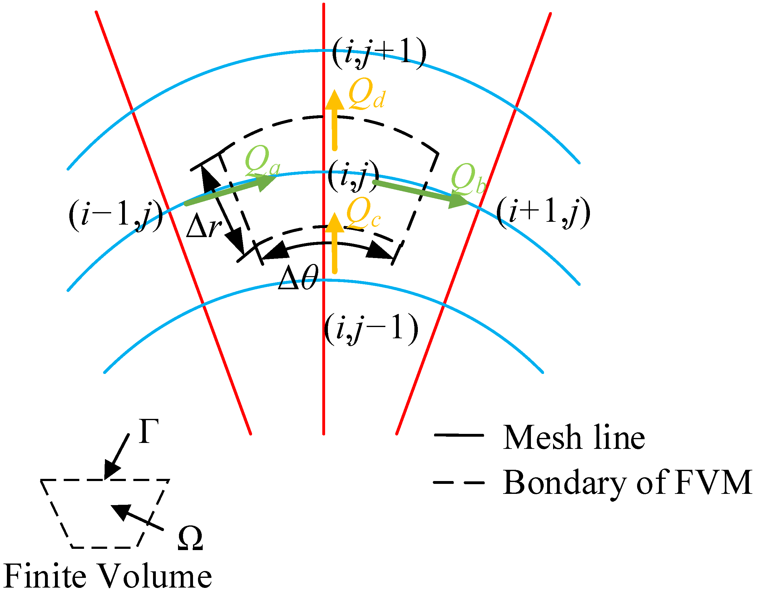
In this study, Equations (4) and (5) are substituted by Equation (3). The air pressure distribution can be obtained by numerically solving the modified Reynolds equation considering the air rarefaction effect by using the finite volume method (FVM). The pressure values at all grid points are iteratively calculated using the successive over-relaxation (SOR) method, as shown in Figure 2.
The flow rate per unit length in (r, θ) is expressed as:
q θ = Λ r ¯ p h ¯ h ¯ Q ˜ p h ¯ h ¯ 3 p h ¯ r ¯ θ .
q r = Q ˜ p h ¯ h ¯ 3 r ¯ p h ¯ r ¯ .
The flows over the cell faces are expressed as:
Q a = Λ r ¯ a p h a ¯ h ¯ a Q ˜ p h a ¯ h ¯ a 3 p h ¯ i , j p h ¯ i 1 , j r ¯ a Δ θ Δ r ¯ .
Q b = Λ r ¯ b p h b ¯ h ¯ b Q ˜ p h b ¯ h ¯ b 3 p h ¯ i + 1 , j p h ¯ i , j r ¯ b Δ θ Δ r ¯ .
Q c = Q ˜ p h c ¯ h ¯ c 3 r ¯ c p h ¯ i , j p h ¯ i , j 1 Δ r ¯ Δ θ .
Q d = Q ˜ p h d ¯ h ¯ d 3 r ¯ d p h ¯ i , j + 1 p h ¯ i , j Δ r ¯ Δ θ .
According to the law of mass conservation, the flow into a control cell is equal to the flow out of the control cell, which is expressed as follows:
Q a Q b + Q c Q d = Λ t p h ¯ h ¯ t ¯ .
In order to simplify the calculation, the quasi-static conditions are assumed for each time step and the squeeze item is ignored. The relationship between a certain node and the surrounding nodes can be obtained as follows:
M i j p h i , j + M i m 1 j p h i 1 , j + M i j p 1 p h i , j + 1 + M i p 1 j p h i + 1 , j + M i j m 1 p h i , j 1 = Q 0 .
where  Q 0 = Λ r a p h a h a r b p h b h b Δ r .
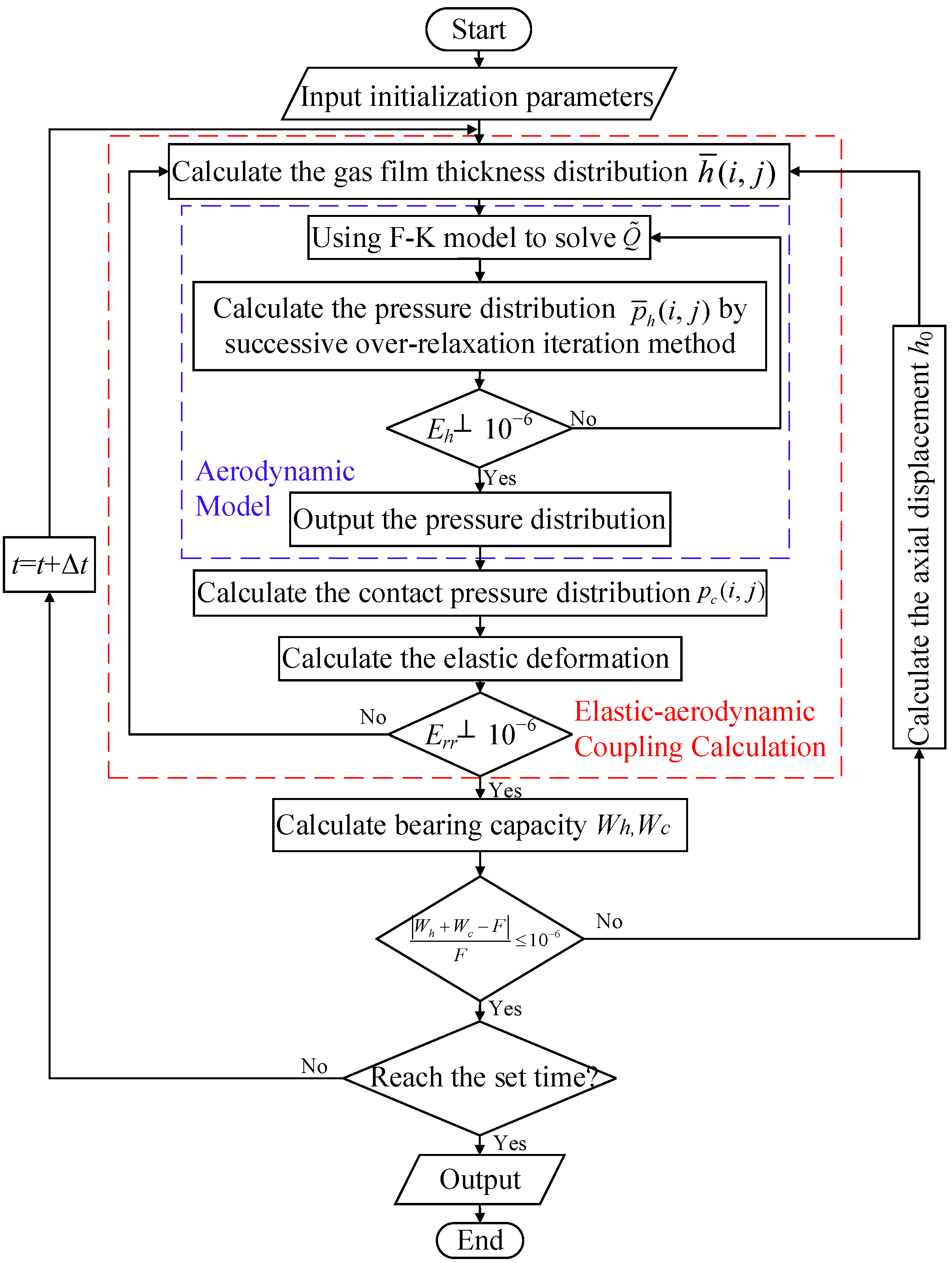
A program was written in MATLAB to solve the transient mixed lubrication problem. The flow-chart of the calculation process of the pressure is shown in the blue dashed box in Figure 3. Since the foil structure is flexible, the foil deforms elastically when air bearing pressure is generated. The calculation process of the elastic—aerodynamic coupling model is shown in the red-line box in Figure 3. When the asperity contact pressure between the foil surface and the rotor surface is generated, the deformation of foil structure will also occur. Therefore, the influence of the foil deformation should also be considered when calculating the asperity contact pressure in the simulation.
In the simulation of the start-up process, the initial speed of the rotor is zero. Then, the rotor speed gradually increases with time. The program calculates step-by-step and judges whether the convergence condition is reached so as to obtain the final result. In order to improve the simulation accuracy and reduce the iteration step size, we set the rotor stable speed RS to be 30 k rpm, the start-up time to be t0 = 0.4 s and the time iteration step to be Δt 10−3 s.

4. Results and Discussions

4.1. Model Validation

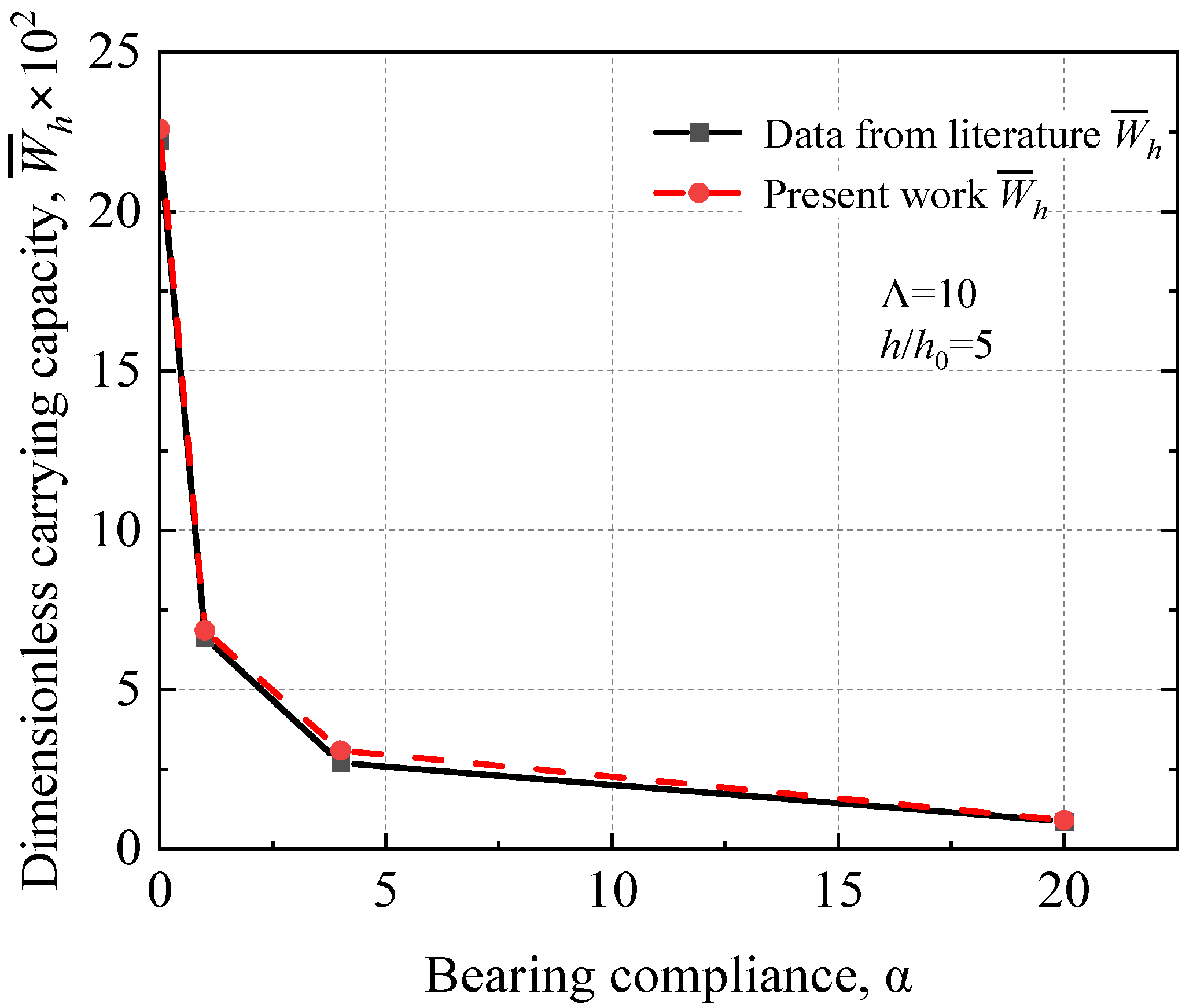
The developed model needs to be verified in order to test its accuracy. However, the literature on the exploration of the start-up process of AFTBs is very limited. The static characteristics predicted by the developed model were compared with the literature [14]. The basic parameters of the AFTB are shown in Table 1.
Figure 4 shows the comparison between the simulation results of the present work and those of the literature under different bearing compliances. The thickness ratio of the air film inlet/outlet and the bearing numbers are set to be constant. It can be observed that their results on dimensionless load carrying capacity are in good agreement, which proves the accuracy and reliability of the developed elastic—aerodynamic model for the AFTB.

4.2. Start-Up Behavior

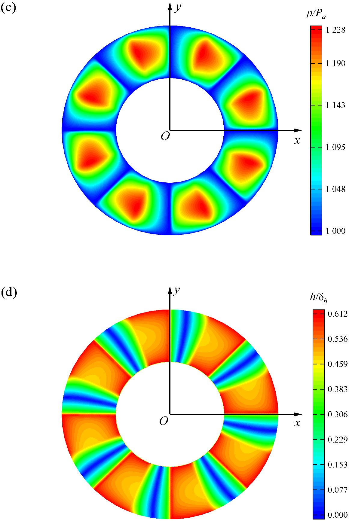
Figure 5 shows the evolution of the tribological performance of AFTB during the start-up process. It is assumed that the bearing compliance α is 0.6 and the external load F is 40 N. In the simulation, the rotor speed increases linearly from 0 to 30 k rpm within 0.4 s. The initial minimum air film thickness is determined based on the load balance between the asperity contact force and external load. Figure 5a shows the evolutions of the rotor speed, the minimum air film thickness and the friction torque over time during the start-up process. In the initial stage of start-up, the rotor speed is low and the aerodynamic effect between the top foil of the AFTB and the rotor is weak. The external load is mainly carried by the asperities. Therefore, the friction torque is large and the minimum air film thickness is low. At this moment, the AFTB operates in the air-solid mixed lubrication state. When the lift-off speed is reached, the AFTB enters full film lubrication. As the rotor speed continues to rise, the effect of the air dynamic pressure increases. During this process, the friction torque increases slightly, and the minimum air film thickness increases significantly. The evolutions of the asperity contact force and the air bearing force with the time during the start-up process are shown in Figure 5b. At the time of 0.047 s, the asperity contact force is zero and the rotor is completely separated from the top foil of the AFTB. At this moment, the rotor speed RS is 3525 rpm, which is referred to as the lift-off speed. Even if the rotor speed continues to increase subsequently, the air bearing force remains constant and equal to the external load. At t0 = 0.4 s, the minimum air film thickness is 15.56 μm and the maximum air bearing pressure p is 1.228 Pa. Figure 5c,d show the 3D air pressure distribution and air film thickness distribution during the stable operation stage, respectively. The elastic—aerodynamic coupling effects can be observed from these two figures. The air pressure acting on the top foil causes the top foil to deform locally.

4.3. Effects of the Air Rarefaction on the Tribological Properties during Start-Up Process

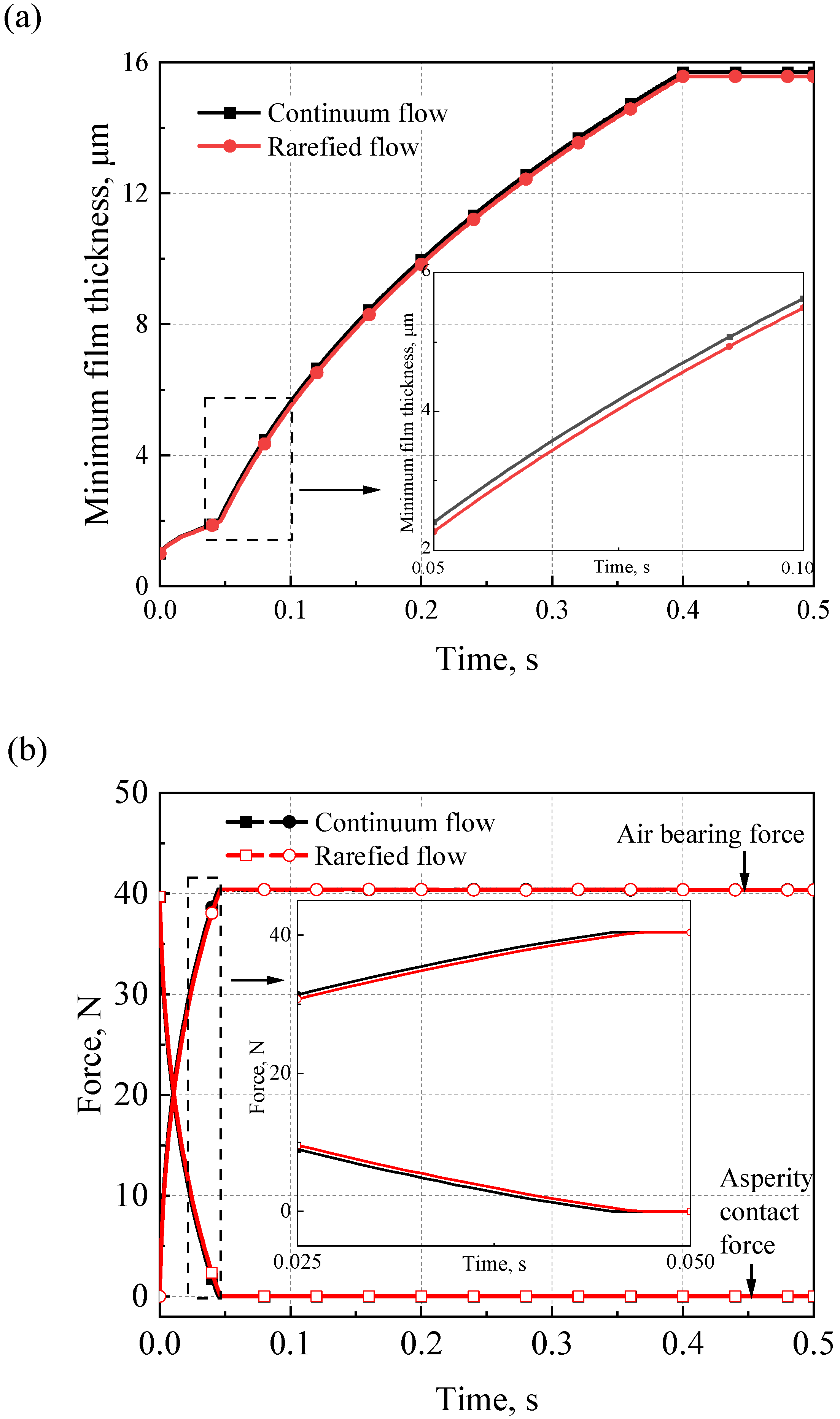
Figure 6 shows the effects of air rarefaction on air film thickness as well as the air bearing force and asperity contact force during the start-up process. Under the same start-up conditions, the air film thickness of the rarefied flow is lower than the continuous flow, as shown in Figure 6a. When t = 0.4 s, the minimum air film thickness of the continuous flow is 15.70 μm, whereas the minimum air film thickness of the rarefied flow is 15.56 μm. Compared to the continuum flow, the air bearing force of the rarefied flow is lower, while the asperity contact force of the rarefied flow is higher, as shown in Figure 6b. This can be attributed to the reduction of the air bearing pressure generated under the rarefied flow condition. In addition, the lift-off time of the AFTB is t = 0.045 s and the lift-off speed is 3375 rpm under the continuous flow condition, while the lift-off time is 0.047 s and the lift-off speed is 3525 rpm under the rarefied flow condition.

4.4. Effects of Bearing Compliance on Start-Up Process

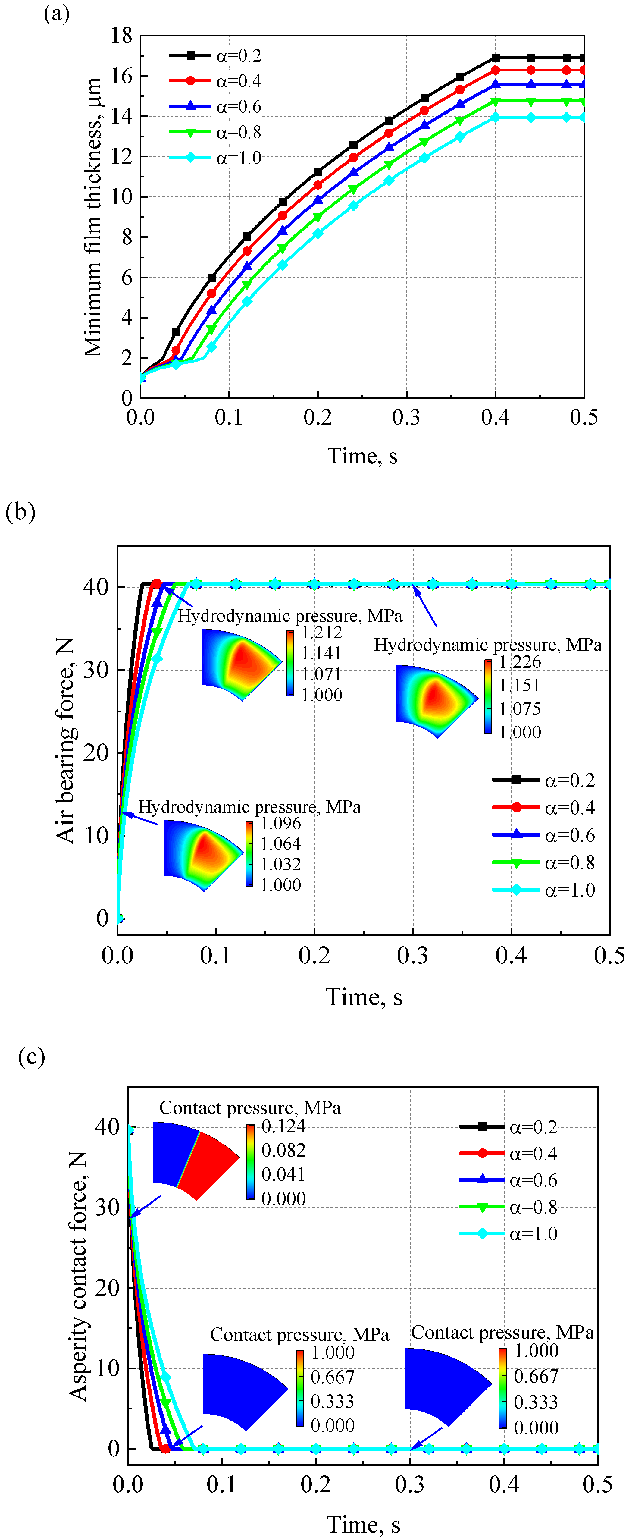
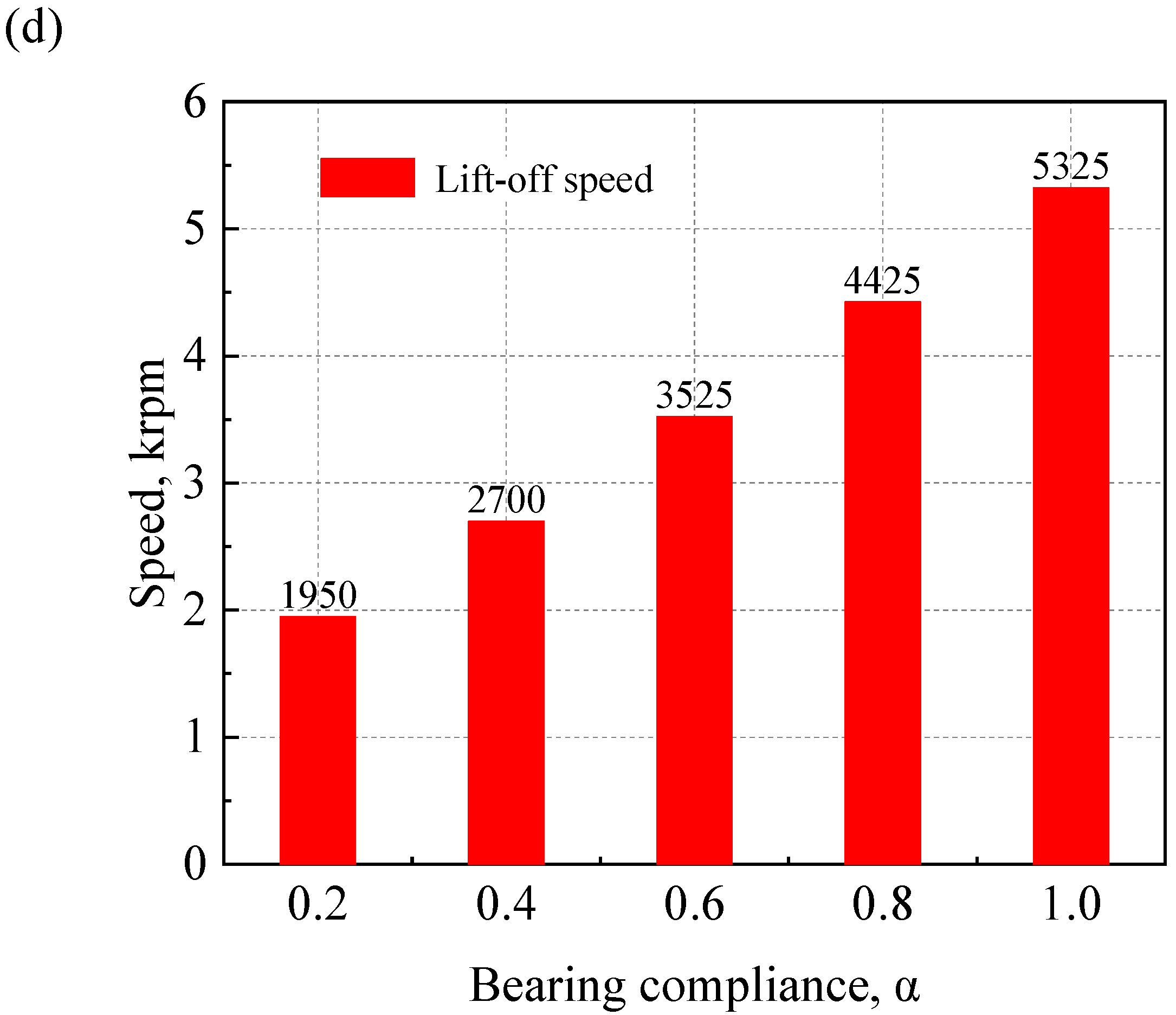
Bearing compliance affects the load-carrying capacity and lift-off characteristics of AFTBs. Figure 7a–c show the evolutions of the minimum air film thickness, air bearing force and asperity contact force with time under different bearing compliances during the start-up process. The external load F is fixed to be 40 N. At the same speed, the minimum air film thickness of the bearing decreases with the increase of bearing compliance. From these figures, it can be seen that the air bearing force and the minimum air film thickness increase faster as the bearing compliance becomes smaller during the start-up process. In contrast, the asperity contact force decreases more quickly. It can be concluded that a smaller bearing compliance is beneficial to improve the start-up performance of the AFTB. The bearing compliance should be chosen carefully in the design of AFTBs. Figure 7b,c show the evolutions of the air bearing pressure and asperity contact pressure with the bearing compliance of 0.6, respectively. It can be clearly seen that the air bearing pressure increases while the asperity contact pressure decreases during the start-up process. Figure 7d shows the effects of the bearing compliances on the lift-off speed. As the bearing compliance increases, the required lift-off speed increases, making lift-off more difficult.

4.5. Changes in Lift-Off Characteristics under Various Loads

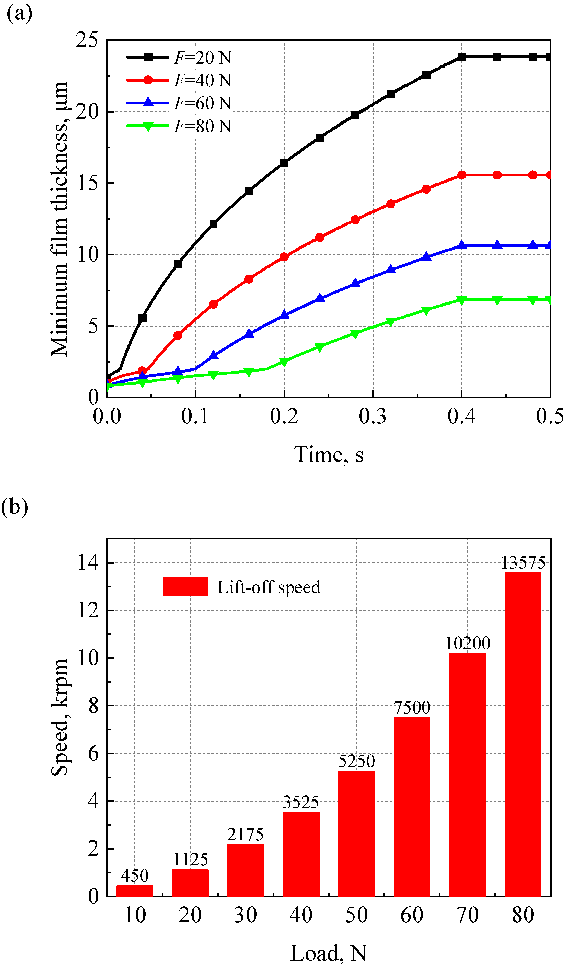
Variation in the external load affects the lift-off characteristics of AFTBs. In the simulation, the bearing compliance α is set to be 0.6 and the external load F ranges from 10 to 80 N. Figure 8a,b show the effects of external loads on the minimum air film thickness and lift-off speed during the start-up process, respectively. As the external load increases, the minimum air film thickness decreases and the lift-off time increases. Furthermore, as the external load increases, the lift-off speed increases. When the load is greater than 40 N, the lift-off speed increases significantly. It shows that the AFTB is difficult to lift-off under heavy load conditions and frequent starts and stops will aggravate the wear of the bearing.

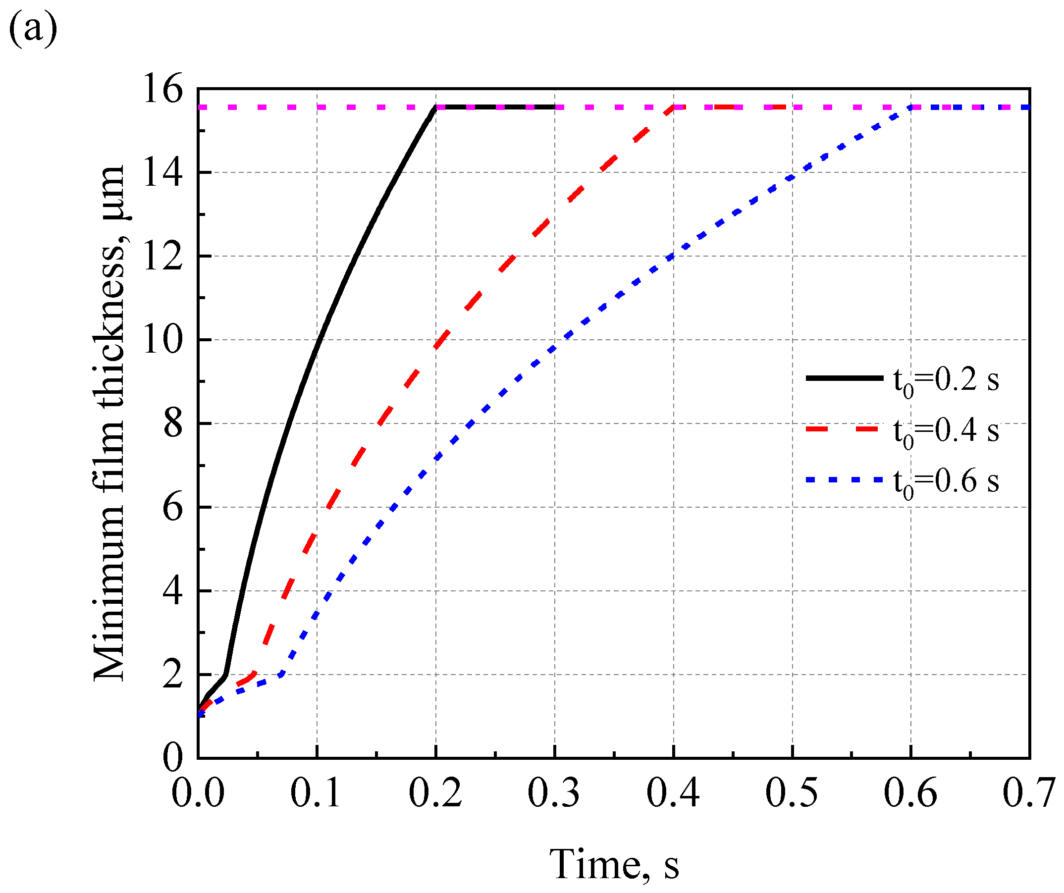
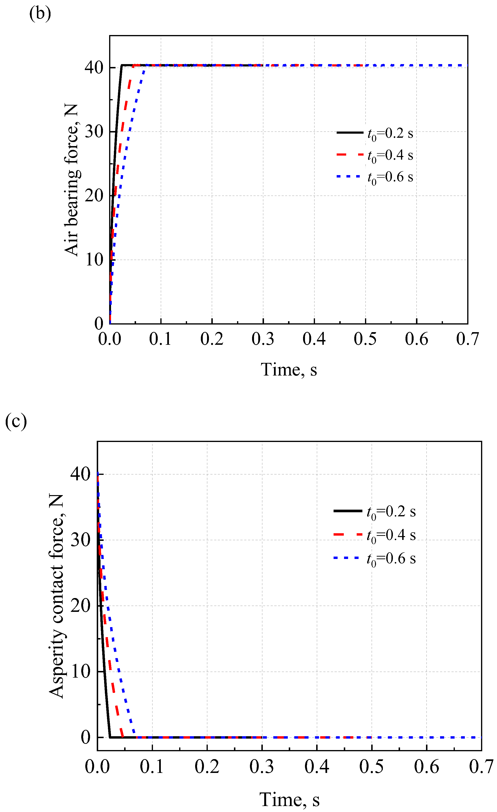
4.6. Effects of Acceleration Time on the Start-Up Process

Figure 9 shows the effects of acceleration time on the start-up performance of AFTBs. Acceleration time is directly related to the acceleration of the rotor. A short acceleration time indicates a higher acceleration of the rotor. It can be seen from Figure 9a that with the same bearing compliance α of 0.6 and external load F of 40 N, air film thickness increases sharply with a shorter start-up time. In addition, as shown in Figure 9b,c, the air bearing force increases sharply and the asperity contact force decreases sharply with the decrease of the start-up time.

4.7. Effect of Contact Stiffness on Start-Up Performance

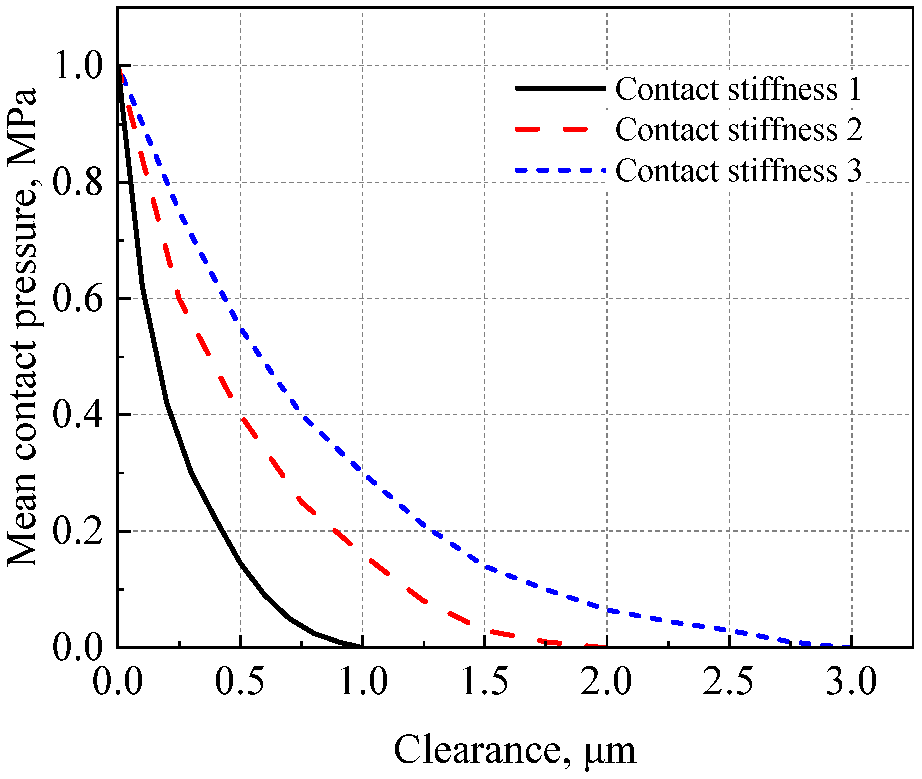
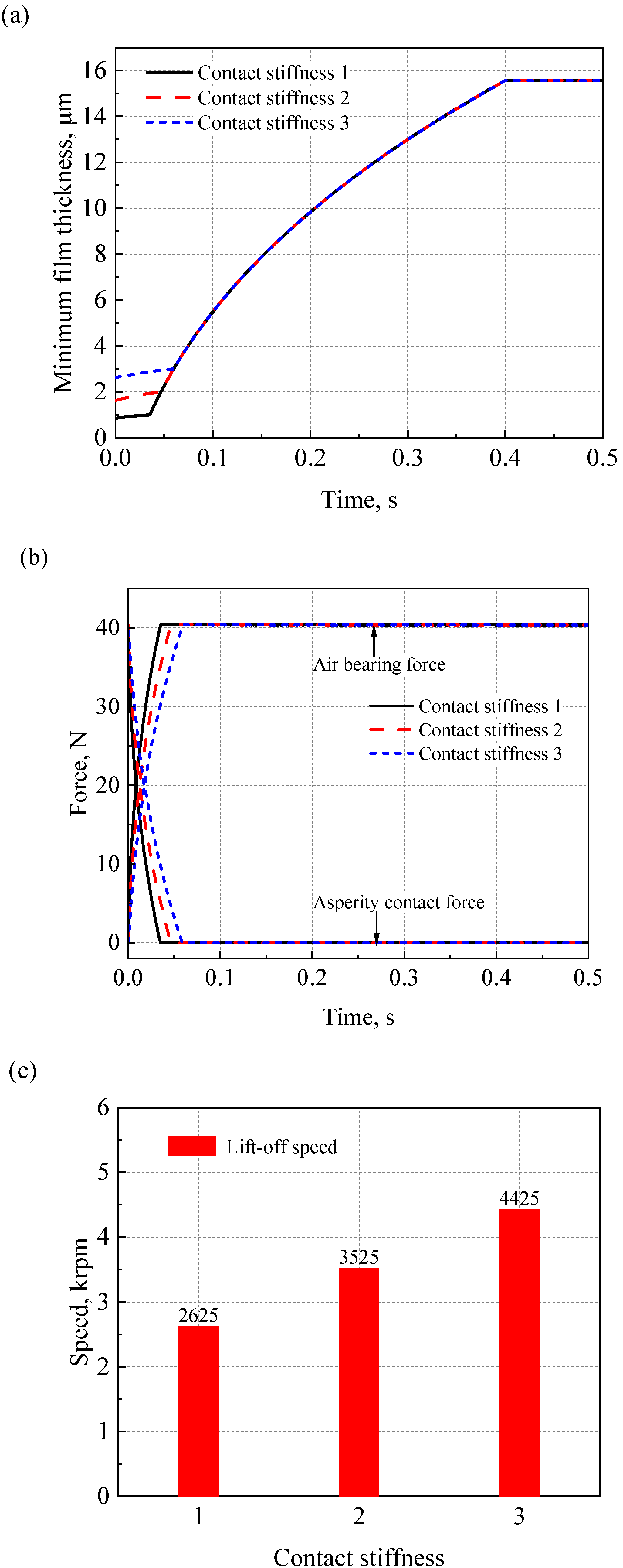
Figure 10 shows the calculated contact stiffness for different rough surfaces. The contact stiffness exhibits a non-linear variation. At the beginning of the contact, the asperity contact pressure is low because only individual asperity peaks are in contact. As the number of asperities in contact increases, the asperity contact pressure increases accordingly. Figure 11a–c show the influence of various contact stiffnesses on the tribological properties of the AFTB during the start-up process. In the simulation, the bearing compliance α is 0.6 and the external load F is 40 N. Contact stiffness affects the initial air film thickness of the AFTB before lift-off. However, the air film thickness after lift-off of the rotor is the same. This can be attributed to the fact that after lift-off, the rotor surface and the top foil surface are out of contact. At this time, the external load is completely carried by the generated air pressure and the asperity contact pressure is zero. Therefore, contact stiffnesses have no effect on the film thickness after lift-off. From these figures, it can be seen that the contact stiffness has a significant effect on the start-up process; the rougher the surface, the harder it is for the bearing to take off. Furthermore, at the same rotational speed, the bearing with the rougher surface has a lower air bearing force and higher contact force. Therefore, a reasonable surface coating design is also one of the key techniques.

5. Conclusions

In this study, the change in the lubrication state of the AFTB is analyzed during the start-up process. Based on the air rarefaction lubrication theory and Newton’s second law, an elastic—aerodynamic coupled mixed lubrication model was established. The accuracy of the developed model was also verified. On this basis, the factors affecting the start-up performance of the AFTB were explored. From the research results, the following conclusions can be drawn:
(1)
Compared to the continuum flow, the minimum air film thickness and air bearing force of the AFTB, considering the rarefied flow effect, are lower. However, the lift-off speed and the asperity contact pressure of the AFTB are higher during the start-up process.
(2)
As the bearing compliance of the AFTB increases, the lift-off speed increases. When the external load of the AFTB increases, the minimum air film thickness decreases and the lift-off speed increases significantly. When the acceleration time of the rotor is shorter, the lift-off time of the bearing decreases. However, the air bearing force rises sharply and the asperity contact force drops sharply.
(3)
The effects of various contact stiffnesses on the start-up performance were explored. It was found that with the increase of the surface roughness, the lift-off speed increases and the contact time of the AFTB becomes longer.
Bearing compliance is directly related to the foil structure parameters. Contact stiffness mainly depends on the coating design of the top foil. A better AFTB design should take into account the comprehensive influence of the factors bearing compliance, contact stiffness and external load. The results presented in this study provide theoretical support for the design of long-life and high-reliability AFTBs.

Author Contributions

Conceptualization, Y.H.; Formal analysis, F.W.; Methodology, Y.H.; Project administration, Y.H.; Software, F.W.; Supervision, Y.H.; Writing—original draft, F.W.; Writing—review & editing, Y.H. All authors have read and agreed to the published version of the manuscript.

Funding

This work was supported by the National Natural Science Foundation of China (Nos. 52275204, 51905298, 52075311) and Shanghai Key Laboratory of Intelligent Manufacturing and Robotics.

Data Availability Statement

Not applicable.

Conflicts of Interest

The authors declare no conflict of interest.

Nomenclature

Mmass of the rotor, kg
bpitch ratio of inclined planeFexternal load, N
Dinverse Knudsen numberWbearing capacity, N
E*equivalent elasticity modulus, PaWhair bearing force, N
hair film thickness, mWcasperity contact force, N
h0minimum film thickness, mTtotal friction torque, N·m
δhthe slope height, mThaerodynamic friction torque, N·m
RSrotational speed, rpmTcasperity contact torque, N·m
Δtthe time step of quasi-static computation, s   W ¯ hdimensionless air bearing force, =Wh/(PaR22)
hdimensionless air film thickness, =h/δh   W ¯ cdimensionless asperity contact force, =Wc/(PaR22)
  h ¯ 0dimensionless minimum film thickness, =h0/δh   T h ¯ dimensionless aerodynamic friction torque, =Th/(PaR22δh)
Paambient pressure, Pa   T ¯ cdimensionless asperity contact torque, =Tc/(PaR23)
pair bearing pressure, PaNpnumber of pads
  p h ¯ dimensionless air bearing pressure, =p/Paμviscosity of air, N·s/m2
pclthe asperity contact pressure on the local scale, N/mm2αbearing compliance
pcthe asperity contact pressure on a global scale, N/mm2Λnumber of bearings
  p ¯ cdimensionless asperity contact pressure, = pc/Paνwhirl frequency, rad/s
R1inner radius, mΩdomain
R2outer radius, mδgap between the two undeformed surfaces, m
r, θaxis of the polar coordinateβangular extension of pad, =45°
r ¯ dimensionless radius, =r/R2ωangular velocity, rad/s
ttime, suthe normal displacement, m
t0start-up period, sx, ythe local scale coordinate
μ0friction coefficient between the top surface and rotor surfacelx, lythe evaluation length and width of the surface roughness

References

  1. Samanta, P.; Murmu, N.; Khonsari, M. The evolution of foil bearing technology. Tribol. Int. 2019, 135, 305–323. [Google Scholar] [CrossRef]
  2. DellaCorte, C. Oil-Free shaft support system rotordynamics: Past, present and future challenges and opportunities. Mech. Syst. Signal Process. 2012, 29, 67–76. [Google Scholar] [CrossRef] [Green Version]
  3. Branagan, M.; Griffin, D.; Goyne, C.; Untaroiu, A. Compliant Gas Foil Bearings and Analysis Tools. J. Eng. Gas Turbines Power 2015, 138, 054001. [Google Scholar] [CrossRef]
  4. Walowit, J.A.; Anno, J.N.; Hamrock, B.J. Modern Developments in Lubrication Mechanics. J. Lubr. Technol. 1977, 99, 304–305. [Google Scholar] [CrossRef]
  5. Kim, T.H.; Andrés, L.S. Heavily Loaded Gas Foil Bearings: A Model Anchored to Test Data. J. Eng. Gas Turbines Power 2008, 130, 012504. [Google Scholar] [CrossRef]
  6. Iordanoff, I. Analysis of an Aerodynamic Compliant Foil Thrust Bearing: Method for a Rapid Design. J. Tribol. 1999, 121, 816–822. [Google Scholar] [CrossRef]
  7. Iordanoff, I. Maximum Load Capacity Profiles for Gas Thrust Bearings Working Under High Compressibility Number Conditions. J. Tribol. 1998, 120, 571–576. [Google Scholar] [CrossRef]
  8. Yan, J.J.; Liu, Z.S.; Zhang, G.W.; Wei, J.Q. Static characteristics analysis of foil thrust bearing considering the rarefied gas effect. JASP 2016, 31, 1521–1529. [Google Scholar]
  9. Samanta, P.; Khonsari, M. The limiting load-carrying capacity of foil thrust bearings. Proc. Inst. Mech. Eng. Part J J. Eng. Tribol. 2017, 232, 1046–1052. [Google Scholar] [CrossRef]
  10. Xie, Z.; Jiao, J.; Yang, K. Experimental and numerical exploration on the nonlinear dynamic behaviors of a novel bearing lubricated by low viscosity lubricant. Mech. Syst. Signal Process. 2023, 182, 109349. [Google Scholar] [CrossRef]
  11. Xu, F.; Chu, J.; Sha, L. Air foil thrust bearings with top foil sagging: Theoretical predictions and experiments. Tribol. Int. 2023, 177, 107995. [Google Scholar] [CrossRef]
  12. Agrawal, G.L. Foil air/gas bearing technology—An overview. Turbo Expo Power Land Sea Air 1997, 78682, V001T04A006. [Google Scholar]
  13. Heshmat, H.; Walowit, J.A.; Pinkus, O. Analysis of Gas-Lubricated Foil Journal Bearings. ASME J. Lubr. Technol. 1983, 105, 647–655. [Google Scholar] [CrossRef]
  14. Heshmat, H.; Walowit, J.A.; Pinkus, O. Analysis of Gas Lubricated Compliant Thrust Bearings. J. Lubr. Technol. 1983, 105, 638–646. [Google Scholar] [CrossRef]
  15. Peng, J.-P.; Carpino, M. Calculation of Stiffness and Damping Coefficients for Elastically Supported Gas Foil Bearings. ASME Trans. J. Tribol. 1993, 115, 20–27. [Google Scholar] [CrossRef]
  16. Peng, J.-P.; Carpino, M. Coulomb Friction Damping Effects in Elastically Supported Gas Foil Bearings. Tribol. Trans. 1994, 37, 91–98. [Google Scholar] [CrossRef]
  17. Peng, J.-P.; Carpino, M. Finite Element Approach to the Prediction of Foil Bearing Rotor Dynamic Coefficients. J. Tribol. 1997, 119, 85–90. [Google Scholar] [CrossRef]
  18. Carpino, M.; Talmage, G. A Fully Coupled Finite Element Formulation for Elastically Supported Foil Journal Bearings. Tribol. Trans. 2003, 46, 560–565. [Google Scholar] [CrossRef]
  19. Liu, J.; Du, F.R. Simulation of Compliant Bump Foil Journal Bearing Using Coupled Reynolds Equation and Finite Element Model Method. Adv. Mater. Res. 2012, 479–481, 2499–2503. [Google Scholar] [CrossRef]
  20. Dunfee, J.D.; Shapiro, W. Start-Stop Testing of Two Self-Acting Air-Lubricated Micro Spiral Grooved Thrust Bearing Coating. NASA-CR-134673 1 April 1974. [Google Scholar]
  21. Jahanmir, S.; Heshmat, H.; Heshmat, C. Assessment of Tribological Coatings for Foil Bearing Applications. Tribol. Trans. 2009, 52, 231–242. [Google Scholar] [CrossRef]
  22. Kim, J.-H.; Blanchet, T.A.; Calabrese, S.J. High Velocity Oxyfuel Deposition for Low Surface Roughness PS304 Self-Lubricating Composite Coatings. Tribol. Trans. 2004, 47, 157–169. [Google Scholar] [CrossRef]
  23. Zhang, C.; Ao, H.; Jiang, H.; Zhou, N. Investigations on start-up performances of novel hybrid metal rubber-bump foil bearings. Tribol. Int. 2020, 154, 106751. [Google Scholar] [CrossRef]
  24. Wang, C.; Wang, X.; Hu, Y. Investigation on start-up performance of gas foil bearing considering wear topography evolution of non-Gaussian surface. Tribol. Int. 2023, 177, 108003. [Google Scholar] [CrossRef]
  25. Meybodi, R.R.; Mohammadi, A.K.; Bakhtiari-Nejad, F. Numerical analysis of a rigid rotor supported by aerodynamic four-lobe journal bearing system with mass unbalance. Commun. Nonlinear Sci. Numer. Simul. 2012, 17, 454–471. [Google Scholar] [CrossRef]
  26. Fukui, S.; Kaneko, R. A Database for Interpolation of Poiseuille Flow Rates for High Knudsen Number Lubrication Problems. J. Tribol. 1990, 112, 78–83. [Google Scholar] [CrossRef]
  27. Fukui, S.; Kaneko, R. Analysis of flying characteristics of magnetic heads with ultra-thin spacings based on the Boltzmann equation. IEEE Trans. Magn. 1988, 24, 2751–2753. [Google Scholar] [CrossRef]
  28. Greenwood, J.A.; Williamson, J.B.P. Contact of nominally flat surfaces. Proc. R. Soc. London. Ser. A 1966, 295, 300–319. [Google Scholar] [CrossRef]
  29. Hu, Y.; Meng, X.; Xie, Y. A computationally efficient mass-conservation-based, two-scale approach to modeling cylinder liner topography changes during running-in. Wear 2017, 386, 139–156. [Google Scholar] [CrossRef]
  30. Hu, Y.; Meng, Y. Theoretical and Experimental Study of Transient Behavior of Spiral-Groove Thrust Bearings during Start-Up. Tribol. Trans. 2019, 63, 154–172. [Google Scholar] [CrossRef]
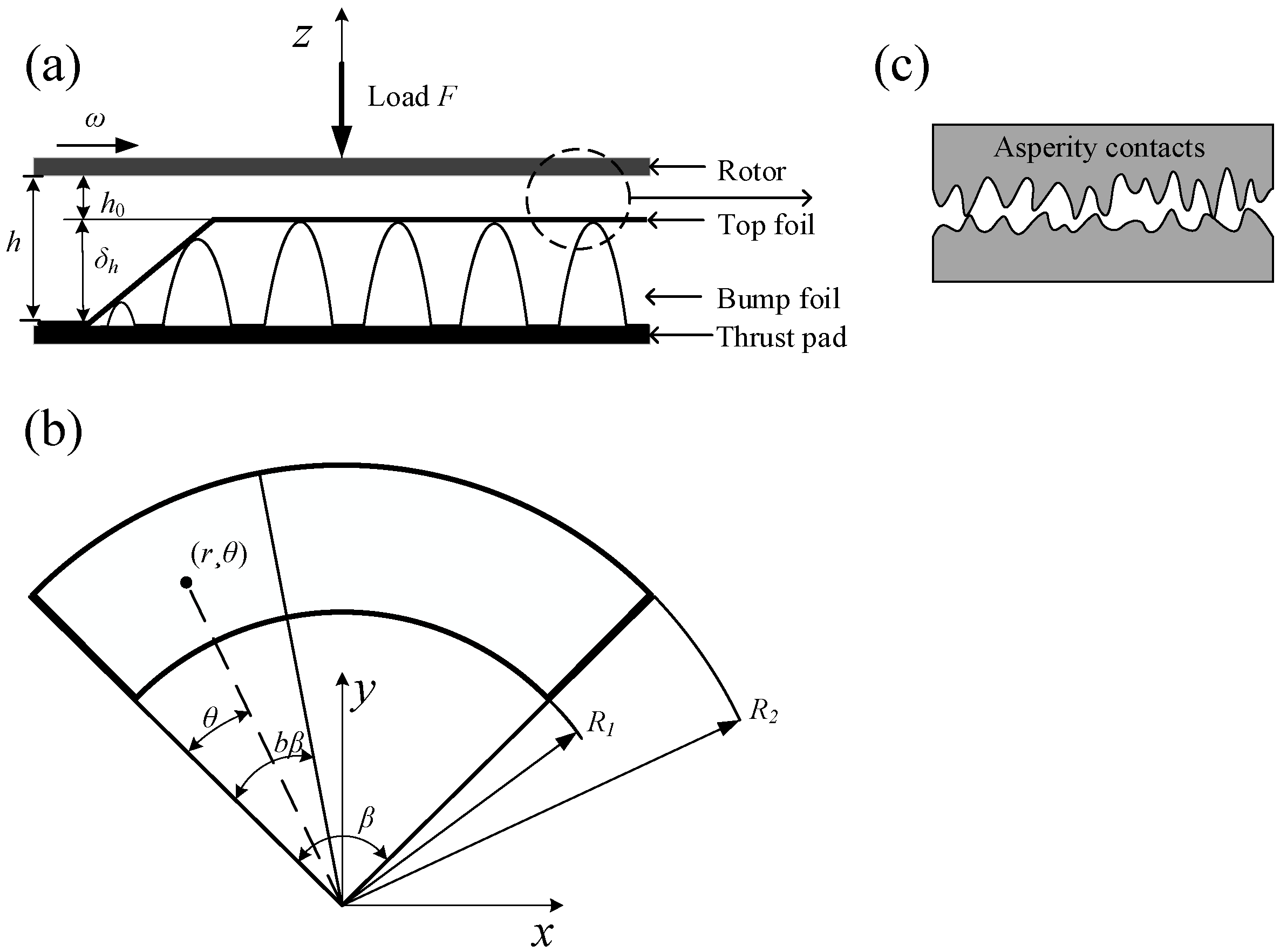
Figure 1. Schematic of the AFTB: (a) front view of thrust bearing; (b) top view of thrust bearing; and (c) asperity contact between the top foil and the rotor surface.
Lubricants 11 00094 g001
Figure 2. Finite volume meshing in cylindrical coordinates.
Lubricants 11 00094 g002
Figure 3. Computer program flowchart.
Lubricants 11 00094 g003
Figure 4. Comparison results for dimensionless load carrying capacity between present work and the literature.
Lubricants 11 00094 g004
Figure 5. (a) Evolution of tribological properties during start-up process; (b) evolution of air bearing force and asperity contact force during start-up process; (c) air pressure distribution at the time of 0.5 s; and (d) the corresponding air film thickness distribution at the same time.
Lubricants 11 00094 g005aLubricants 11 00094 g005b
Figure 6. Effects of air rarefaction on (a) air film thickness and (b) air bearing force and asperity contact force during start-up process.
Lubricants 11 00094 g006
Figure 7. Effects of bearing compliance on (a) air film thickness; (b) air bearing force; (c) asperity contact force; and (d) lift-off speed.
Lubricants 11 00094 g007aLubricants 11 00094 g007b
Figure 8. Effects of the external load on (a) air film thickness and (b) lift-off speed.
Lubricants 11 00094 g008
Figure 9. Effects of acceleration time on start-up behavior: (a) air film thickness; (b) air bearing force; and (c) asperity contact force.
Lubricants 11 00094 g009aLubricants 11 00094 g009b
Figure 10. Various contact stiffnesses for AFTBs.
Lubricants 11 00094 g010
Figure 11. Effects of various contact stiffnesses on the start-up process: (a) air film thickness; (b) air bearing force, asperity contact force; and (c) lift-off speed.
Lubricants 11 00094 g011
Table 1. AFTB geometrical and material properties [14].
ParametersValues
Outer radius (R2)40 mm
Inner radius (R1)20 mm
Equivalent elasticity modulus214 GPa
Pitch ratio of inclined plane (b)0.5
Angular extension of pad (β)45°
Number of pads (Np)8
Gas film inlet/outlet thickness ratio (h/h0)5
Bearing numbers(Λ)10
Bearing compliance (α)0, 1, 4, 20
Disclaimer/Publisher’s Note: The statements, opinions and data contained in all publications are solely those of the individual author(s) and contributor(s) and not of MDPI and/or the editor(s). MDPI and/or the editor(s) disclaim responsibility for any injury to people or property resulting from any ideas, methods, instructions or products referred to in the content.