Article

Analysis of Nonlinear Time-Domain Lubrication Characteristics of the Hydrodynamic Journal Bearing System

1
China Ship Scientific Research Center, Wuxi 214082, China
2
Taihu Laboratory of Deep-Sea Technological Science, Wuxi 214082, China
3
State Key Laboratory of Deep-Sea Manned Vehicles, Wuxi 214082, China
4
College of Shipbuilding Engineering, Harbin Engineering University, Harbin 150001, China
*
Author to whom correspondence should be addressed.
Lubricants 2023, 11(3), 145; https://doi.org/10.3390/lubricants11030145
Submission received: 1 February 2023 / Revised: 14 March 2023 / Accepted: 15 March 2023 / Published: 17 March 2023
(This article belongs to the Special Issue Water-Lubricated Bearings)

Abstract

:
The nonlinear time-domain lubrication characteristics of the hydrodynamic journal bearing system are studied in this paper. The motion equation of the hydrodynamic journal bearing system is established based on the balance of the relationship among the water film force, journal inertia force, and external load. The water film pressure distribution of the sliding bearing is calculated by the finite difference method. Firstly, the variation law of the water film pressure distribution with time under the external periodic load is calculated considering the inertial force of the journal. The influence of the initial eccentricity on the orbit of the journal center is studied. Secondly, the maximum water film pressure, the orbit of the journal center, eccentricity, water film pressure, and the minimum water film thickness of the bearing under the action of circumferential and unidirectional periodic external loads are calculated, and the effects of inertial force and rotational speed on the dynamic characteristics of the bearing are analyzed. Finally, the water film dynamic characteristics under low speed and heavy load are studied. The result shows that the pressure of the dimensionless water film caused by inertial force is reduced by 7 to 10 percent at the rotational speed between 200 r/min and 800 r/min, which means that the influence of inertia force cannot be ignored.

1. Introduction

Radial sliding bearing is a widely used bearing in the industry. It has the advantages of strong bearing capacity, stable operation, good vibration resistance, and long life, and it is widely used in various fields [1]. Traditional sliding bearings use greases as lubricants. High-viscosity lubricants generate more heat during operation, and the problem of lubricant leakage during operation is even more serious, especially for oil-lubricated bearings used in water machinery. Oil pollution seriously damages the water environment [2,3]. Using water instead of oil as a lubricating medium can not only save a lot of oil but also avoid environmental pollution caused by using oil as a lubricating medium [4,5]. At the same time, water-lubricated bearings have low cost, good flame retardance, easy maintenance, and can also reduce the friction, wear, vibration, noise, non-functional consumption, and other key problems of friction pairs. Therefore, water-lubricated bearings are widely used in ship stern shaft, water turbine, water pump, water turbine, steam turbine, and other equipment. For example, Canada’s Thomson-Golden Co., Ltd. (Canada) adopted a water lubrication system in the support of the ship’s stern shaft and compounded a layer of polymer material on the stainless-steel bearing as the bearing bush. Water-lubricated bearings are widely used in centrifugal pumps and marine centrifugal pumps in Japan. The Hayward Taylor Company of the United Kingdom has adopted water-lubricated sliding bearings in the structure of the packless pump. Vickers and Michell of Germany use water-lubricated rubber bearings in deep well pumps and submersible pumps [6].
The hydrodynamic journal bearing system could be considered to be a typical rotor-bearing system. Accurately grasping the lubrication characteristics of the rotor-bearing system has important guiding significance for the optimization of and vibration and noise design of the engineering machinery system [7,8]. When the mechanical system is running, the clearance of the rotor-bearing system is in a constantly changing state. Therefore, the lubrication state of the rotor-bearing system has strong time-varying characteristics, which are very complex to solve [9]. The commonly simplified method is to use the infinitely short bearing or infinitely long bearing theory to study nonlinear dynamic characteristics and the instability of the rotor-bearing system [10,11,12]. Brancati et al. studied the nonlinear dynamic characteristics of rigid unbalanced rotors supported by oil film bearings. A short bearing theory was adopted to solve the oil film force. The results showed that the rotor exhibited periodic and one-half periodic vibration under the nonlinear oil film force [13,14]. Li et al. adopted the infinite length bearing model and presented the approximate analytic expressions of the periodic solution of the non-linear rotor-bearing system [15]. Lin et al. established a comprehensive finite element model considering the nonlinear force of the water film and the flexibility of the propeller blade for a propeller-shaft system. The long-bearing approximation was adopted to calculate the nonlinear force of the water film. The research shows that the rotor will exhibit complex dynamic behavior under nonlinear oil film, such as bifurcation, stability problems, chaos, etc. [16,17]. Cai et al. studied the effects of wear and shaft-shape error defects on the tribo-dynamic responses of water-lubricated bearings under non-linear propeller disturbances using a numerical model. Scholars have adopted various methods to solve the water film force [18].
It is important to improve mathematical models for more accurate prediction of bearing characteristics. With the continuous development of numerical calculation technology, the lubrication characteristics can also be analyzed in detail. Some scholars have conducted research by establishing numerical models of water-lubricated bearings. Singh et al. used the two-dimensional Reynolds equation to study the changes in bearing film thickness, bearing capacity, and temperature field under different journal speeds [19]. Kornaeva et al. developed a simulation model to calculate the flow of viscous incompressible fluid in the annular channel under the influence of vibration. The effect of boundary flow of low-viscosity fluids was determined [20]. Xie et al. used finite difference method to study the lubrication mechanism and performance parameters of water-lubricated bearing considering wall sliding and inertia force and studied the influence of wall sliding and inertia force on performance parameters [21]. Gao et al. used computational fluid dynamics (CFD) to analyze the influence of the eccentricity ratio on the water film pressure distribution, and numerical analysis was carried out for different sizes of sliding bearings at different speeds. Based on the analysis, a reference has been provided for the selection of the initial diameter for the design of high-efficiency water-lubricated plain bearings under a given load and rotational speed [22]. Wang et al. combined computational fluid dynamics and fluid-structure coupling to study the effect of elastic deformation on load-carrying capacity [23]. Through experimental studies, some academics have shown that obvious bushing wear would occur at the edge of the water-lubricated bearing working under the fluid lubrication state [24,25]. Sun et al. established a transient model of a ship propeller rotor-bearing system to study the system response and lubrication performance [26].
Due to the action of load and the rotational speed, there form an eccentricity and the corresponding convergent and divergent water films between the bearing and the journal. In a convergent area, the pressure is very large, and the resultant force resists the external load, and correspondingly the external load will directly affect the dynamic pressure of the water film. It should be noted that the journal itself has an acceleration under the action of external loads, not only in the direction of velocity but also in the magnitude that both are changed when the external force varies with time. In this case, the presence of inertial forces is bound to have an impact on the operation of the bearing. At the same time, the influence of inertia force on the lubrication characteristics of water-lubricated bearings is studied, which is of great significance to improve the lubrication performance of bearings. Compared with oil-lubricated bearings, water-lubricated bearings are more difficult to converge during time-domain simulation, especially when the inertial force is considered, which poses great challenges to the present paper.
The nonlinear time-domain lubrication characteristics of the hydrodynamic journal bearing system are studied in this paper. Firstly, on the basis of the Reynolds equation, when solving the force equilibrium equation, the relevant theoretical formulas were derived, taking into account the inertial force caused by acceleration and the centripetal force caused by circular motion. The variation law of the water film pressure distribution with time under the external periodic load was calculated considering the inertial force of the journal. The influence of the initial eccentricity on the orbit of the journal center was studied. Secondly, the maximum water film pressure, the orbit of the journal center, eccentricity, and the minimum thickness of the water film of the bearing under the action of circumferential and unidirectional periodic external loads were calculated, and the effects of inertial force and rotational speed on the dynamic characteristics of the bearing were analyzed. Finally, the water film dynamic characteristics under low speed and heavy load are studied.

2. Numerical Procedures

The sketch map of hydrodynamic journal bearing geometry is shown in Figure 1. The origin of the coordinate system is at the center of the bearing. The x-axis points to the left, and the y-axis points down.  h = c + e cos θ denotes the thickness of the water film, and the water film expands along  θ , direction, and  s = θ R ; the attitude angle,  ϕ , is defined as the angle between the maximum thickness of the water film and the  x axis; the angular velocity is  ω ; the distance between the journal center and the bearing center is the eccentricity,  e ξ and  η point to the radial and tangential direction; the absolute clearance is  c = R r ; and the journal center displacement in  x and  y directions is defined as  u = e cos ϕ , v = e sin ϕ .

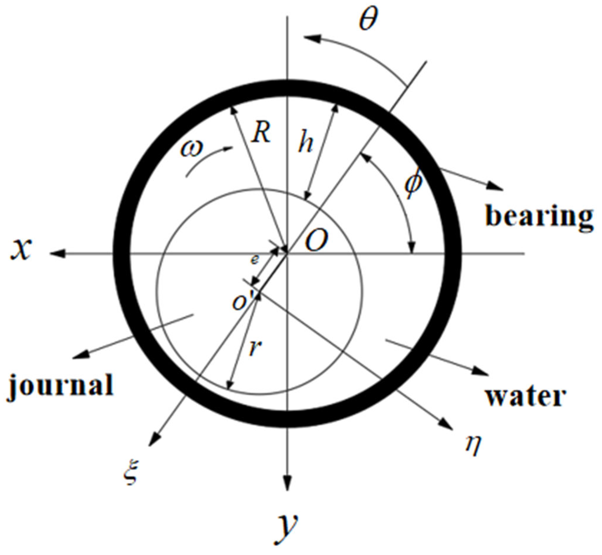
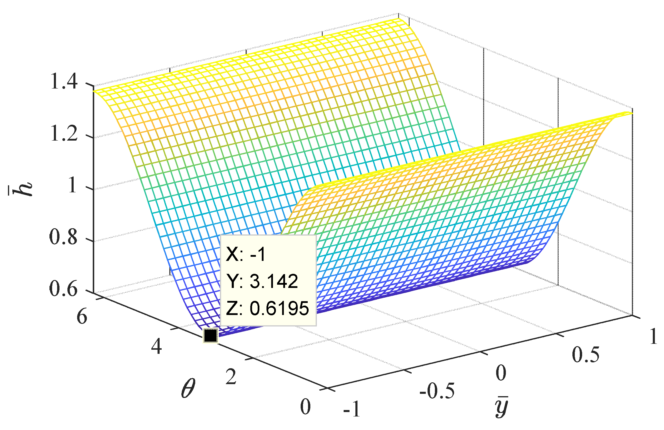
2.1. Governing Equation and Boundary Conditions

According to the actual situation of water-lubricated bearings, we made the following assumptions:
(1)
The film thickness is far smaller than the radius of curvature of the adjacent solid surface;
(2)
The water film pressure in the thickness direction is constant;
(3)
Only the velocity gradient in the film thickness direction is considered;
(4)
The lubricant is in an isothermal and incompressible state.
The water film between the bearing and the journal satisfies the Reynolds equation and this equation can be written as
s ( h 3 η 0 p s ) + z ( h 3 η 0 p z ) = 6 [ U h s + 2 h t ]
Substituting the water film thickness  h = c + e cos θ into Equation (1) gives
s ( h 3 η 0 p s ) + z ( h 3 η 0 p z ) = 6 [ ω h θ + 2 e t cos θ + 2 e sin θ ϕ t ]      
By using  h θ = e sin θ , Equation (2) can be further written as
s ( h 3 η 0 p s ) + z ( h 3 η 0 p z ) = 6 [ ( ω 2 ϕ t ) h θ + 2 e t cos θ ]      
In which,  ω , ϕ t , e t , and  η 0 , respectively, denote angular velocity of the axial, variation rate of offset angel, variation rate of offset displacement, and dynamic viscosity.

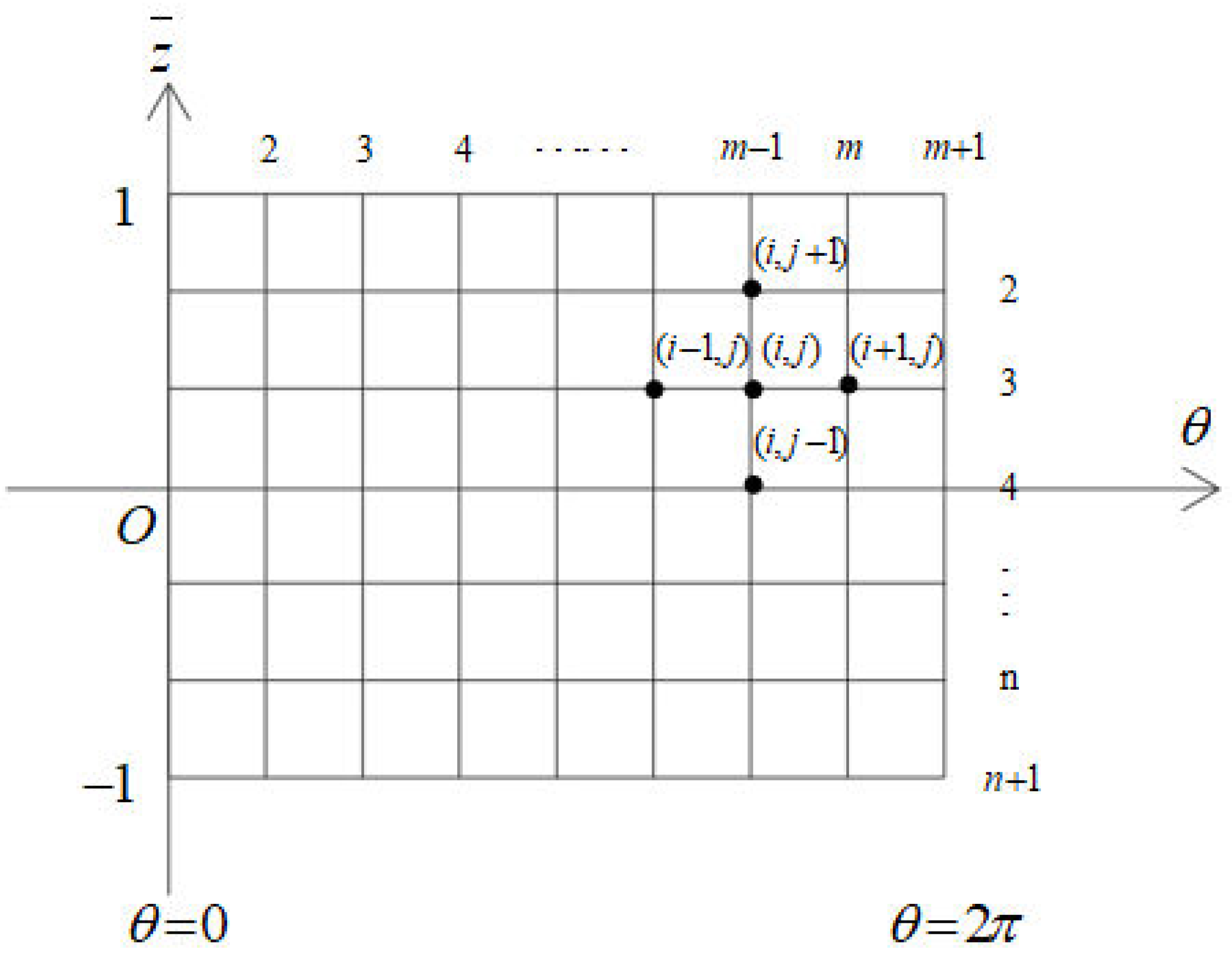
2.2. Discretisation of the Governing Equation

In order to make the complex formula form compact and highlight the role of related factors, the Reynolds equation will be solved in a dimensionless form. The following dimensionless transformation is adopted:
s = θ R θ = s / R z = z ¯ ( L / 2 ) z ¯ = z / ( L / 2 ) , 1 z ¯ 1 h ¯ = h / c = 1 + ε cos θ ; p ¯ = p / p 0 ; p 0 = 6 η 0 ( ω 2 ϕ / t ) ( R / c ) 2 q = 2 ε t / ( ω 2 ϕ / t )
By substituting the equation  p = p 1 + q p 2 into Equation (3), the following equation can be derived
s ( h 3 η 0 p 1 s ) + z ( h 3 η 0 p 1 z ) = 6 ( ω 2 ϕ / t ) h θ       s ( h 3 η 0 p 2 s ) + z ( h 3 η 0 p 2 z ) = 6 c ( ω 2 ϕ / t ) h c e
Substituting the dimensionless form in Equation (4) into Equation (5) gives
p 0 c 3 η 0 R 2 θ ( h ¯ 3 p ¯ 1 θ ) + p 0 c 3 η 0 ( L / 2 ) 2 z ¯ ( h ¯ 3 p ¯ 1 z ¯ ) = 6 c ( ω 2 ϕ / t ) h ¯ θ       p 0 c 3 η 0 R 2 θ ( h ¯ 3 p ¯ 2 θ ) + p 0 c 3 η 0 ( L / 2 ) 2 z ¯ ( h ¯ 3 p ¯ 2 z ¯ ) = 6 c ( ω 2 ϕ / t ) h ¯ 1 ε
The dimensionless Reynolds equation is obtained by simplifying Equation (6)
      θ ( h ¯ 3 p ¯ 1 θ ) + R 2 ( L / 2 ) 2 z ¯ ( h ¯ 3 p ¯ 1 z ¯ ) = h ¯ θ θ ( h ¯ 3 p ¯ 2 θ ) + R 2 ( L / 2 ) 2 z ¯ ( h ¯ 3 p ¯ 2 z ¯ ) = h ¯ 1 ε
Letting  q = A ¯ / B ¯ , then   A ¯ = 2 d ε / d t , B ¯ = ω 2 d ϕ / d t . Substituting it into Equation (7) gives
p ( θ ) = [ B ¯ p 1 ¯ ( θ ) + A ¯ p 2 ¯ ( θ ) ] η 0 ( R c ) 2
The finite difference method is used to solve the  p 1 ¯ ( θ ) and  p 2 ¯ ( θ ) in Equation (8). Expand the water film of the bearing bush into a rectangle along  θ , direction, as shown in Figure 2. The  θ direction is the circumferential direction of the water film,  θ = 0 is the starting edge of the water film, and  θ = 2 π is the end edge of the water film. We then divide the  θ direction into m grids and divide the  y ¯ direction into n grids. The width (step length) of each grid in the  θ direction is  Δ θ = 2 π / m , and the width of each grid in the  y ¯ direction is  Δ y ¯ = 2 / n . The dimensionless pressure value at node  ( i , j ) is represented by  p ¯ ( i , j ) , and the pressure value at each node is used to form each order difference quotient, which approximately replaces the derivative in the Reynolds equation and then can be based on the four nodes  ( i 1 , j ) ( i , j + 1 ) ( i + 1 , j ) , and  ( i , j 1 ) around the  ( i , j ) node to calculate the pressure value of the intermediate node.
At present, the mass conservation boundary conditions (also known as JFO boundary conditions) double Reynolds boundary conditions, and Reynolds boundary conditions proposed by Jakobsson, Floberg and Olsson based on hydraulic cavitation theory are the three boundary conditions commonly used in bearing numerical solutions [27]. Although the Reynolds boundary condition does not meet the conditions of conservation of lubricating oil quality at the boundary of oil film rupture and reformation, it meets the requirements of this paper because it is an easy-to-solve numerical method and the calculation accuracy is in line with the requirements of this paper. The boundary conditions used are Reynolds boundary conditions. When calculating the water film pressure distribution, each line is calculated point by point from the starting edge to the ending edge. If the calculated pressure value at a certain point is negative, the pressure value is zero. This point is taken as the approximate position of the natural rupture edge of the water film on the line, and the pressure at all points after this point is zero, making the approximate position of the rupture edge approach the natural boundary conditions.
The difference schemes for solving  p 1 ¯ , p 2 ¯ are as follows
p ¯ 1 , i , j = A i , j p ¯ 1 , i + 1 , j + B i , j p ¯ 1 , i 1 , j + C i , j * p ¯ 1 , i , j + 1 + D i , j * p ¯ 1 , i , j 1 F 1 , i , j E i , j ; p ¯ 2 , i , j = A i , j p ¯ 2 , i + 1 , j + B i , j p ¯ 2 , i 1 , j + C i , j * p ¯ 2 , i , j + 1 + D i , j * p ¯ 2 , i , j 1 F 2 , i , j E i , j
where
A i , j = 2 h ¯ 3 i + 1 2 , j ; B i , j = 2 h ¯ 3 i 1 2 , j ; C i , j = ( D L × Δ ϕ Δ λ ) 2 h ¯ 3 i , j + 1 2 ; D i , j = ( D L × Δ ϕ Δ λ ) 2 h ¯ 3 i , j 1 2 ; E i , j = A i , j + B i , j + C i , j + D i , j ; F 1 , i , j = Δ ϕ h i + 1 , j h i 1 , j 2 ; F 2 , i , j = Δ ϕ 2 cos ϕ ;
The carrying capacity of water film in x and y directions is
W x = R L η 0 ( R c ) 2 [ B ¯ p 1 ¯ cos ( θ + ϕ ) d θ d z ¯ + A ¯ p 2 ¯ cos ( θ + ϕ ) d θ d z ¯ ] W y = R L η 0 ( R c ) 2 [ B ¯ p 1 sin ( θ + ϕ ) d θ d z ¯ + A ¯ p 2 sin ( θ + ϕ ) d θ d z ¯ ]

2.3. Solution Procedure with Translational Inertial Force and Centripetal Force

When the inertia force of the journal is not considered, the external load is directly balanced with the water film force. The force balance equations in x and y directions are listed as follows
W x + G x = 0 W y + G y = 0
where  G x and  G y are external loads.
With  W 0 = 3 R L η ( R c ) 2 , there are
m 1 = W 0 p 1 ¯ cos ( θ + ϕ ) d θ d z ¯ ,   m 2 = W 0 p 2 ¯ cos ( θ + ϕ ) d θ d z ¯ m 3 = W 0 p 1 ¯ sin ( θ + ϕ ) d θ d z ¯ ,   m 4 = W 0 p 2 ¯ sin ( θ + ϕ ) d θ d z ¯
The force balance equation is simplified as
[ m 1 m 2 m 3 m 4 ] [ B ¯ A ¯ ] = [ G x G y ]
When considering the journal inertial force and centripetal acceleration along the radial and tangential direction of the line connecting the axis and the maximum water film thickness, the inertial force balance equation is listed as follows
I ξ = M c d 2 ε d t 2 = W ξ + G ξ + M c ε ( d ϕ d t ) 2 I η = M c ε d 2 ϕ d t 2 = W η + G η
Using the force transformation relationship, the radial and tangential water film forces are decomposed into x and y directions, and the following equations can be obtained:
W x = W ξ cos ϕ W η sin ϕ W y = W ξ sin ϕ + W η cos ϕ
The relationships between eccentricity ratio and deflection angle and the acceleration of axial neck center are as follows:
2 x / t 2 = c 2 ε / t 2 cos ϕ e 2 ϕ / t 2 sin ϕ 2 y / t 2 = c 2 ε / t 2 sin ϕ + e 2 ϕ / t 2 cos ϕ
The force balance equation considering journal inertia force is listed as
[ M 0 0 M ] [ 2 x / t 2 2 y / t 2 ] + [ c x x c x y c y x c y y ] [ x / t y / t ] + [ k x x k x y k y x k y y ] [ x y ] = [ G x G y ] F c [ cos ϕ sin ϕ ] F c = m c ε ( d ϕ d t ) 2
where  F c is centripetal force.
When the bearing is not subjected to external loads, the water film force in the x, y direction is decomposed into a radial force  W ξ and tangential force  W η
W ξ = p cos θ d s W η = p sin θ d s
At this point, the relationship between the water film force and the stiffness coefficient and journal center displacement is as follows
W x = W ξ cos ϕ W η sin ϕ = k x x e cos ϕ + k x y e sin ϕ W y = W ξ sin ϕ + W η cos ϕ = k y x e cos ϕ + k y y e sin ϕ
After simplification, the dimensioned stiffness coefficient is expressed by radial and tangential water film forces:
k x x = W ξ / e k x y = W η / e k y x = W ξ / e k y y = W η / e
In the process of solving the force balance equation considering the inertial force, the stiffness coefficient is solved according to the above equation, and the damping coefficient matrix is replaced by the following equation:
[ W x W y ] = [ m 1 m 2 m 3 m 4 ] [ ω 0 ] | t = t 0 + 2 [ m 1 m 2 m 3 m 4 ] [ ϕ / t ε t ]                                                                                   = [ m 1 m 2 m 3 m 4 ] [ ω 0 ] + 2 [ m 1 m 2 m 3 m 4 ] [ sin ϕ / e cos ϕ / e cos ϕ / c sin ϕ / c ] [ x / t y / t ] = [ k x x k x y k y x k y y ] [ x y ] + [ c x x c x y c y x c y y ] [ x / t y / t ]
In the time-domain calculation in this paper, the stiffness coefficient and damping coefficient is replaced by other variables, and then the time-domain iterative solution is performed.
Considering  A ¯ = 2 ε t , B ¯ = ω 2 ϕ / t , replacing Equation (17) with Equation (18) gives
[ M 0 0 M ] [ c 2 ε / t 2 cos ϕ e 2 ϕ / t 2 sin ϕ c 2 ε / t 2 sin ϕ + e 2 ϕ / t 2 cos ϕ ] + [ m 1 m 2 m 3 m 4 ] [ B ¯ A ¯ ] = [ G x G y ] F c [ cos ϕ sin ϕ ]
Simplifying Equation (23) gives
c 2 ε / t 2 [ M 0 0 M ] [ cos ϕ sin ϕ ] e 2 ϕ / t 2 [ M 0 0 M ] [ sin ϕ cos ϕ ] + [ m 1 m 2 m 3 m 4 ] [ ω 2 ϕ / t 2 ε / t ] = [ G x G y ] F c [ cos ϕ sin ϕ ]
A more concise format is written as
2 ε / t 2 [ c M cos ϕ c M sin ϕ ] + 2 ϕ / t 2 [ e M sin ϕ e M cos ϕ ] ϕ / t [ 2 m 1 2 m 3 ] + ε / t [ 2 m 2 2 m 4 ] + [ m 1 m 2 m 3 m 4 ] [ ω 0 ] = [ G x G y ] F c [ cos ϕ sin ϕ ]
Backward difference scheme is adopted to solve  ε / t ,   ϕ / t in this paper. The difference scheme is as follows
2 ε / 2 t ( s + 1 ) = ( ε / t ( s + 1 ) ε / t ( s ) ) / d t 2 ϕ / 2 t ( s + 1 ) = ( ϕ / t ( s + 1 ) ϕ / t ( s ) ) / d t
Substituting the difference Equation (26) into the simplified force balance equation gives
( ( ε / t ( s + 1 ) ε / t ( s ) ) / d t ) [ c M cos ϕ c M sin ϕ ] + ( ( ϕ / t ( s + 1 ) ϕ / t ( s ) ) / d t ) [ e M sin ϕ e M cos ϕ ] ϕ / t ( s + 1 ) [ 2 m 1 2 m 3 ] + ε / t ( s + 1 ) [ 2 m 2 2 m 4 ] + [ m 1 m 2 m 3 m 4 ] [ ω 0 ] = [ G x G y ] F c [ cos ϕ sin ϕ ]
The final difference forms for solving  ε / t and  ϕ / t are written as
[ c M cos ϕ / d t + 2 m 2 c M sin ϕ / d t + 2 m 4 e M sin ϕ / d t 2 m 1 e M cos ϕ / d t 2 m 3 ] [ ε / t ( s + 1 ) ϕ / t ( s + 1 ) ] = [ G x G y ] [ m 1 m 2 m 3 m 4 ] [ ω 0 ] + ε / t ( s ) [ c M cos ϕ / d t c M sin ϕ / d t ] + ϕ / t ( s ) [ e M sin ϕ / d t e M cos ϕ / d t ]
Through Equation (28), the force balance equation considering inertial force is solved.

2.4. Iterative Method

In this paper, the iterative method is used for numerical calculation. Firstly, the bearing bush is expanded along the axis, with n nodes (n = 40) in the axis and m nodes in the circumferential direction. When calculating water film pressure, iterates from starting point to ending point. Assuming that the internal pressure of each point is zero, the pressure of each point is calculated by finite difference method. If a point pressure is negative, the water film rupture at this point is determined to be zero, and the first approximation of the water film pressure is obtained. The approximate value was used to recalculate the pressure value from the first point again. The overrelaxation iteration method was used to calculate the pressure value on the middle node by using the pressure value of four nodes around node  ( i , j ) . The node pressure was corrected until the iteration error range was met to obtain the water film pressure distribution of each node.
To determine whether the results of each iteration satisfy sufficient accuracy to determine whether the iteration terminated, the following relative convergence criteria were adopted:
i = 2 m j = 2 n | P i , j s + 1 P i , j s | i = 2 m j = 2 n | P i , j s + 1 | δ
This allows the relative error value, δ, to generally take 10−3~10−5. In this paper, the relative error value takes 10−3.

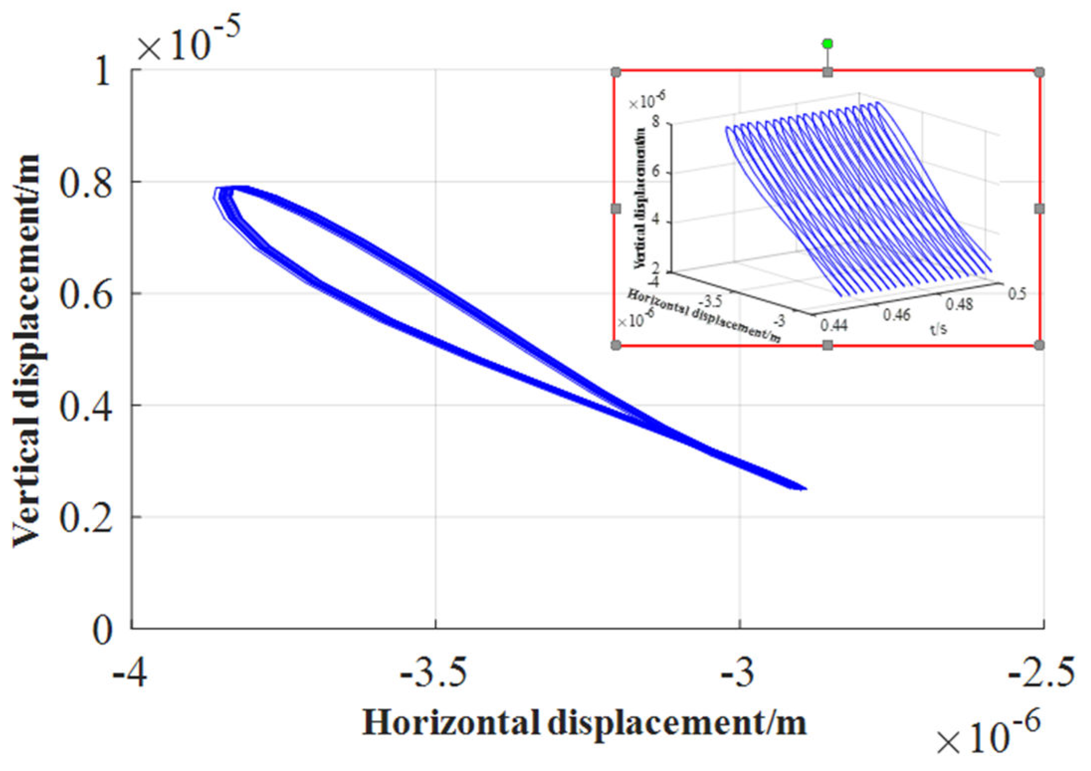
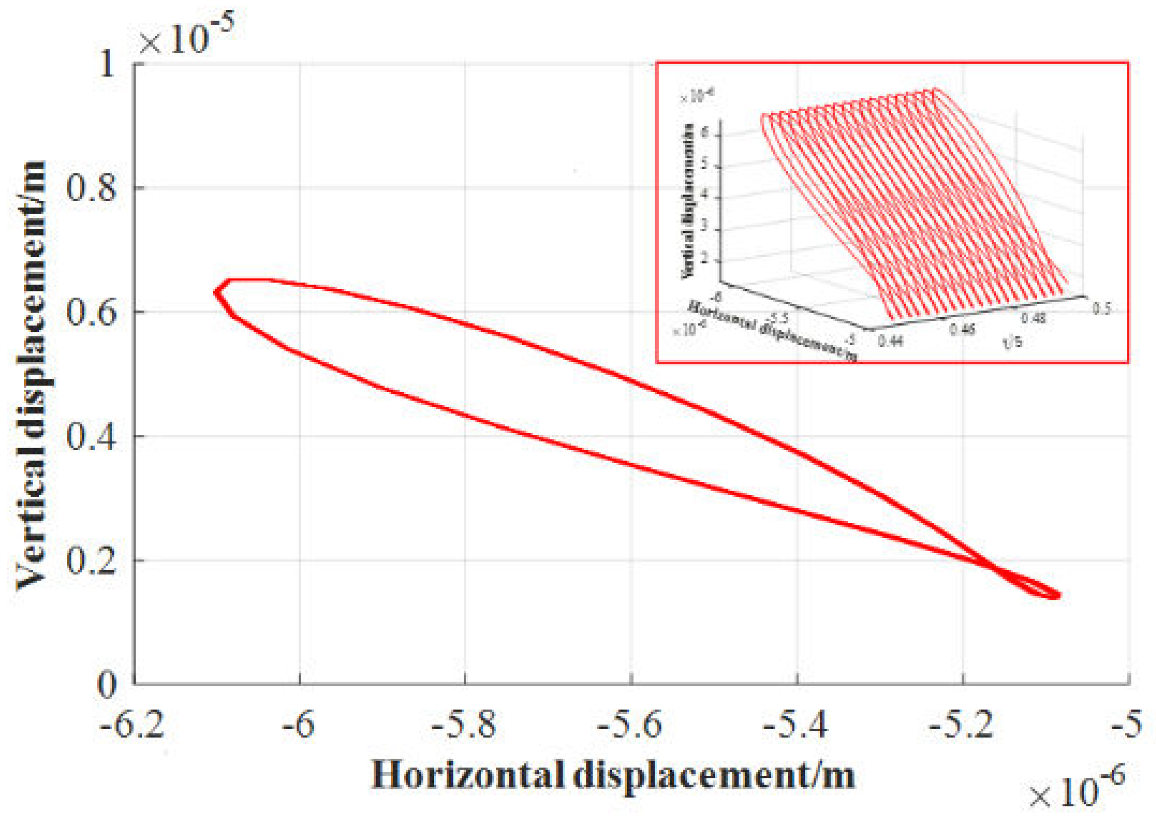
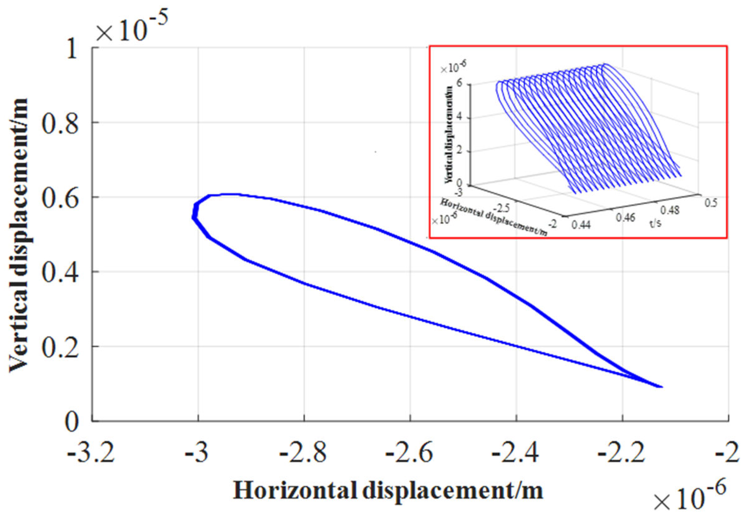
3. Analysis of Water Film Dynamic Characteristics Considering Journal Inertial Force
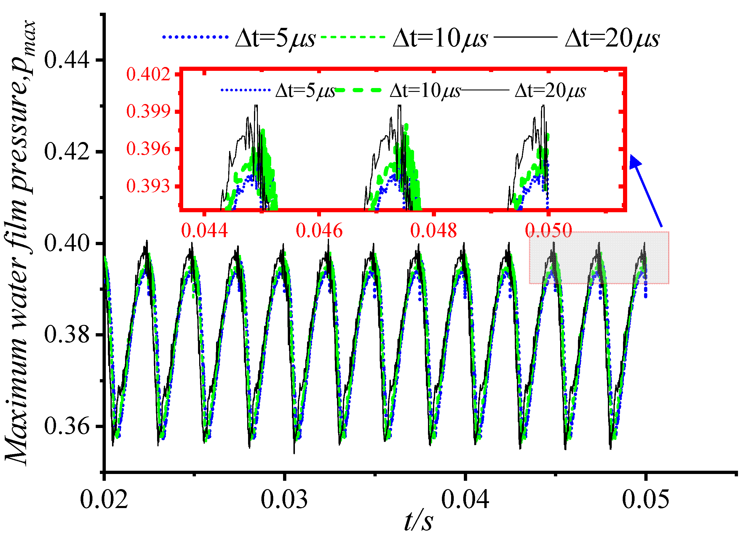
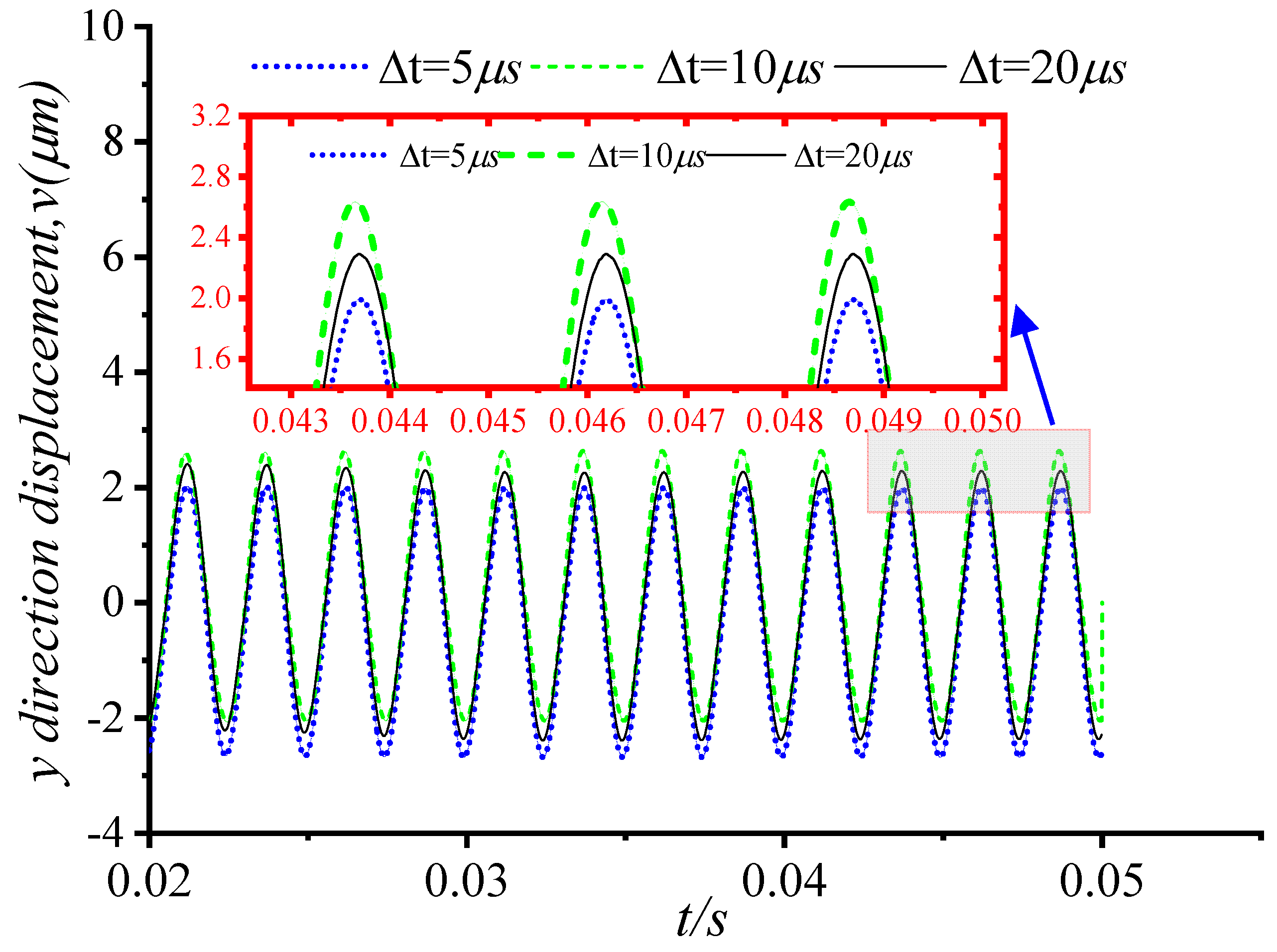
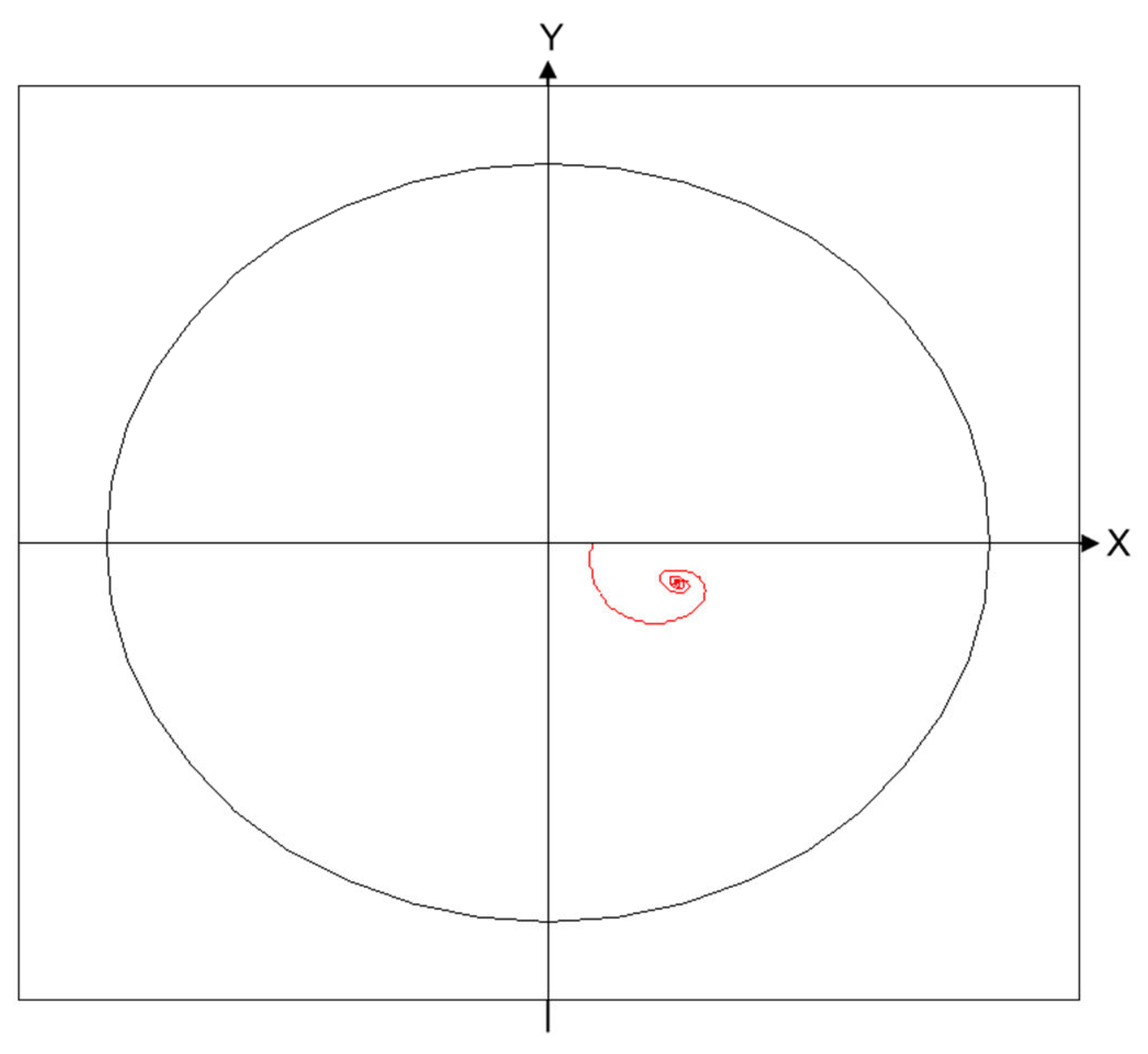
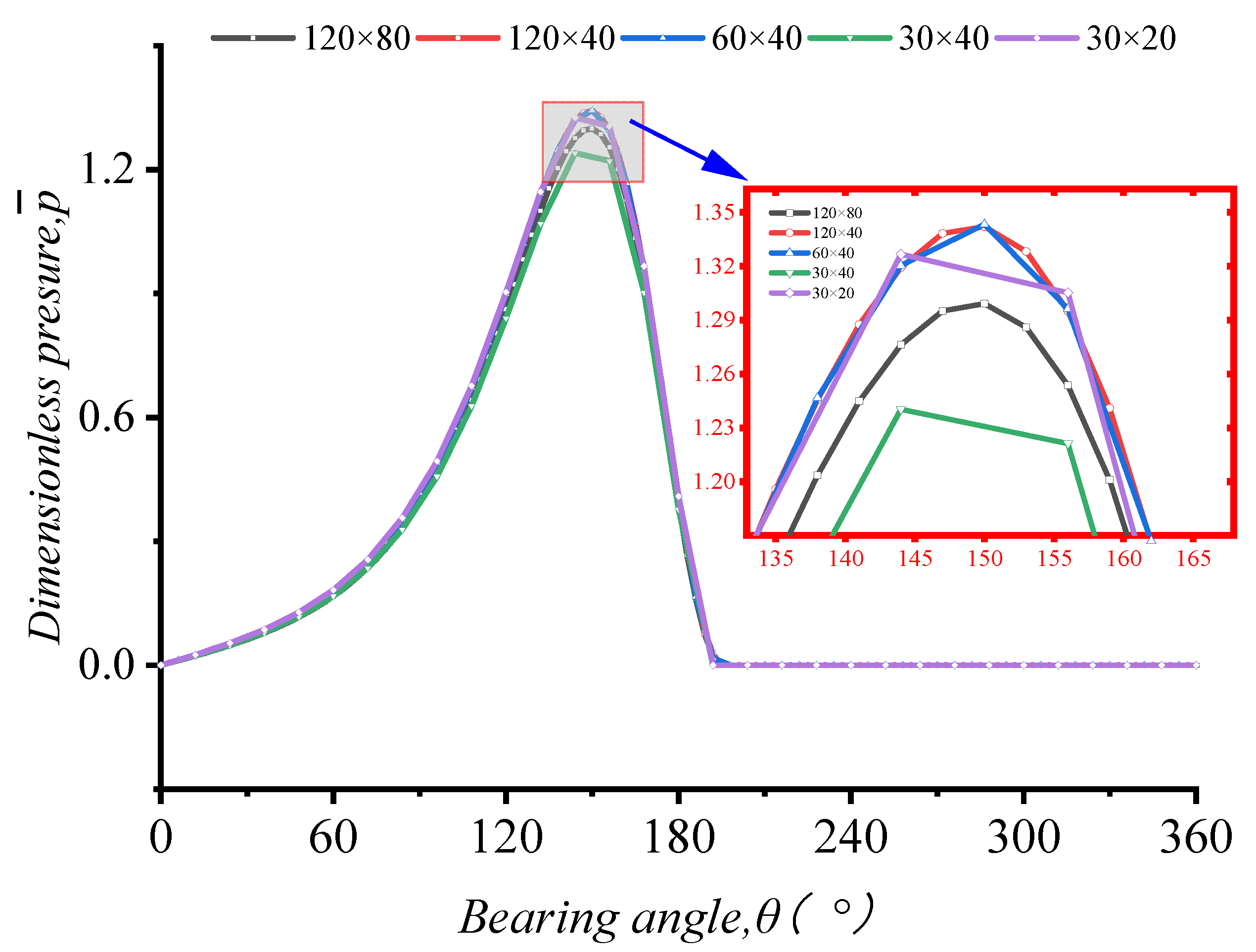
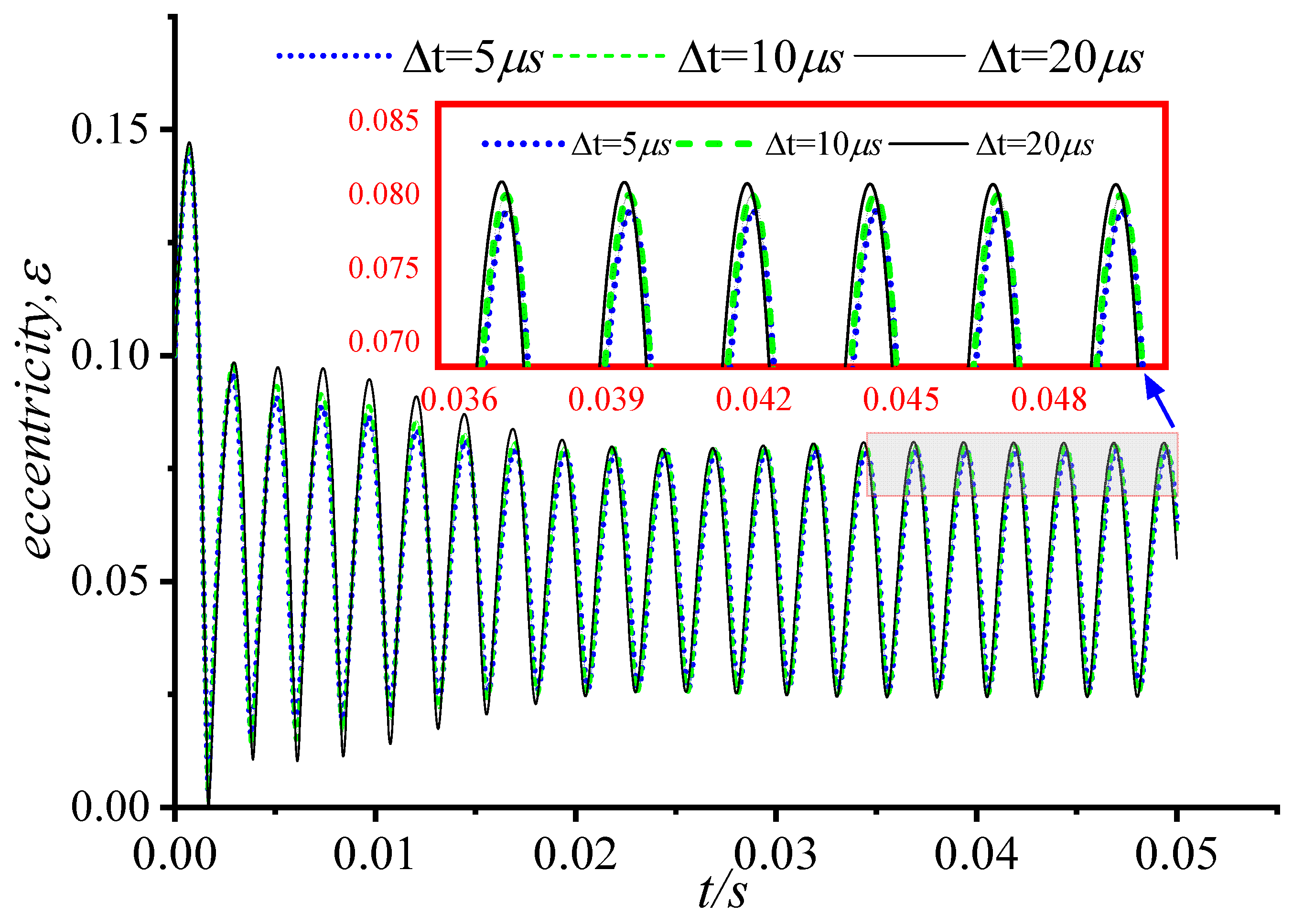
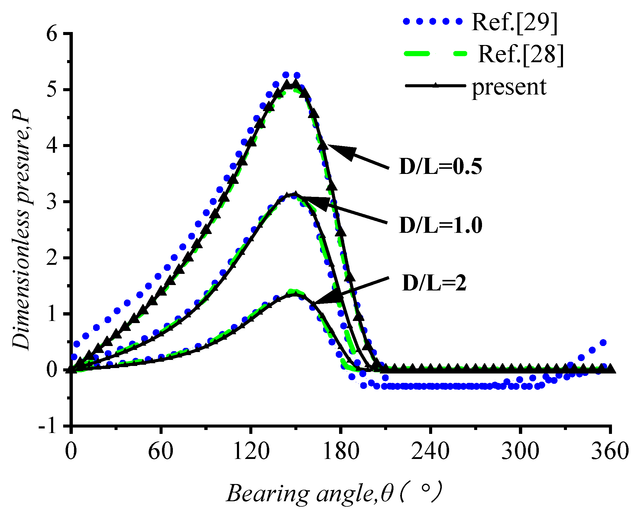
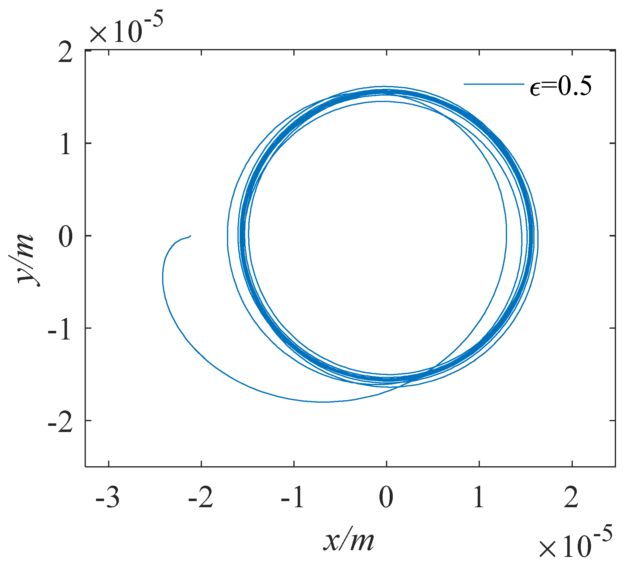
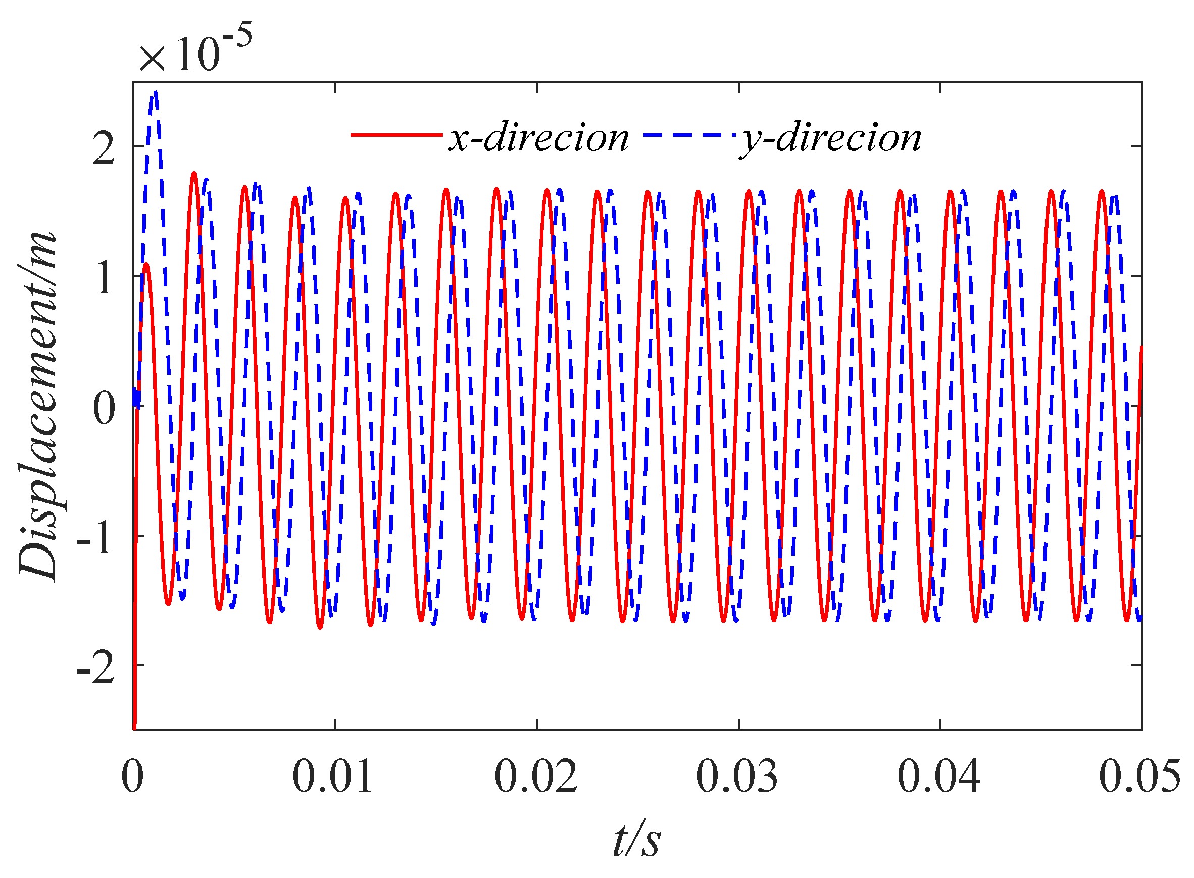
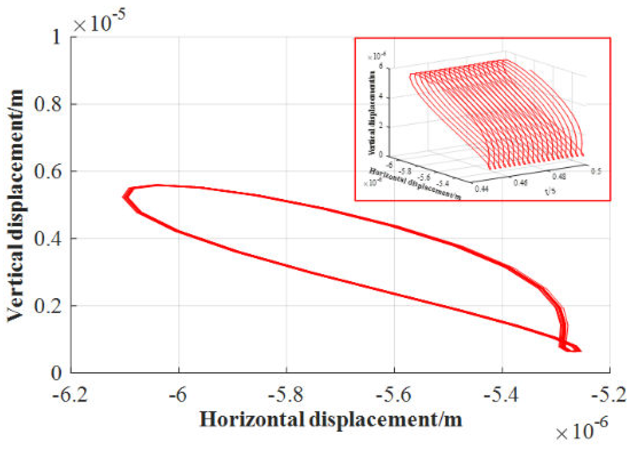
3.1. Validation

For the model in this paper, the convergence analysis of the number of meshes and time steps was carried out. The results of the grid number convergence verification are shown in Figure 3, and the time step convergence verification is shown in Figure 4, Figure 5 and Figure 6. Figure 3 shows the comparison of dimensionless water film pressure under the working conditions of five groups of different grid numbers, and the second and third mesh quantities can better meet the convergence, and considering the problem of calculation efficiency, m = 60 and n = 40 are used to divide the grids in subsequent calculations. Selecting 10 μs for the time step can better meet the convergence requirements.
After convergence analysis, to validate the model used, the pressure distributions on the middle ring of the journal for different bearing diameter-to-length ratios were compared with the results calculated using a finite difference method [28], and the results were calculated using the CFD method [29] in dimensionless form. Table 1 shows the simulation parameters used in the research. The result and the comparison are shown in Figure 7 and Figure 8. From Figure 7, it can be seen that for D/L = 0.5, 1, and 2, the pressures from θ = 0° to 180° computed in this work are in very good agreement with those computed using the method in [28,29]. However, the Reynolds boundary conditions do not predict the reformation of the film, and the pressures from the position where the film ruptures to θ = 360° are all set to zero.
In addition, the finite bearing orbit was calculated under the condition that the external load of the journal is its own gravity and the inertia force of the journal is not considered, as shown in Figure 9. The calculation parameters refer to the parameters in [30]. Figure 9 shows a single trajectory starting from rest concentrically and spiraling gradually towards the equilibrium point under a downward gravity force. The orbit of Figure 9 is remarkably similar to one published by Booker [30] using the mobility method. Thus, the correctness of the calculation method in this paper is further verified.

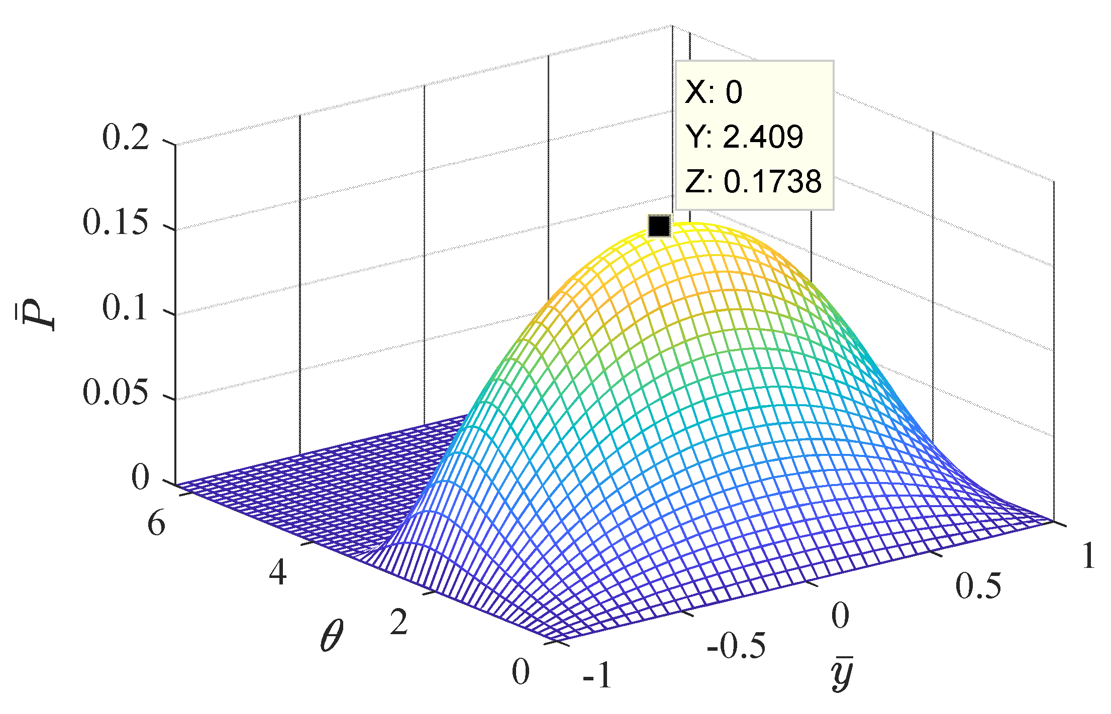
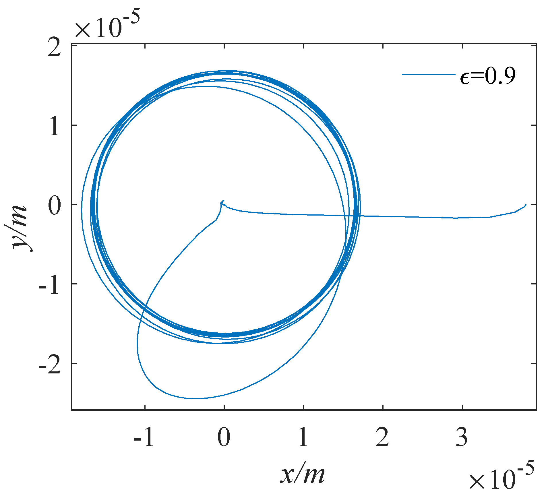
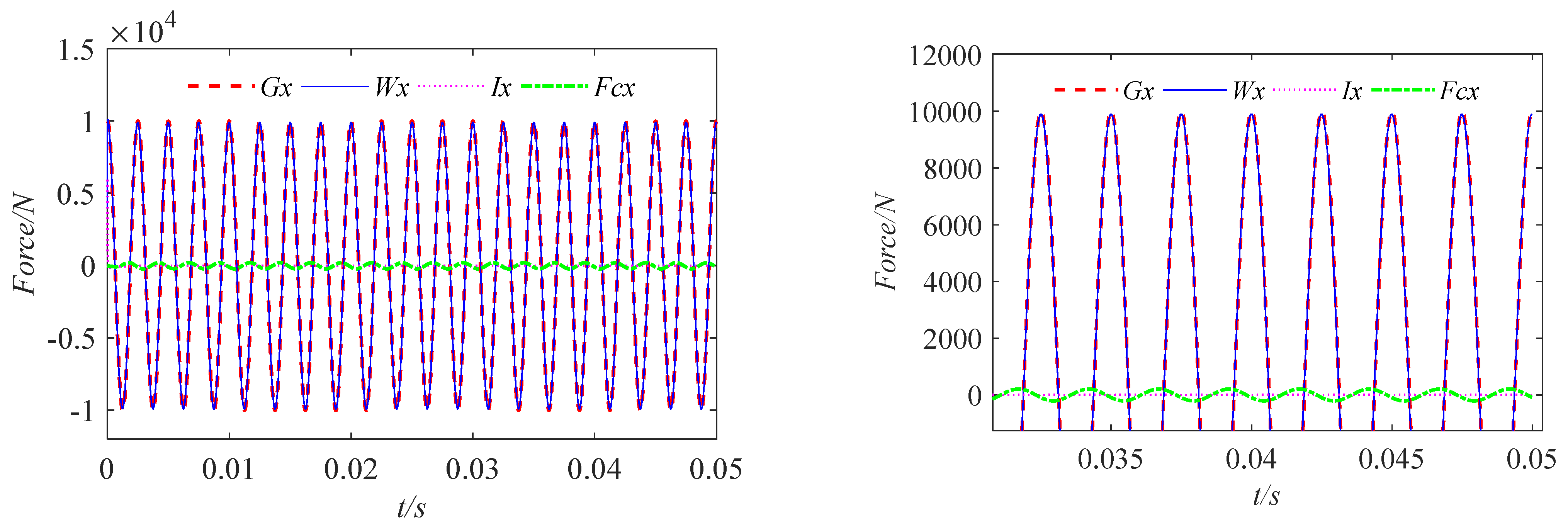
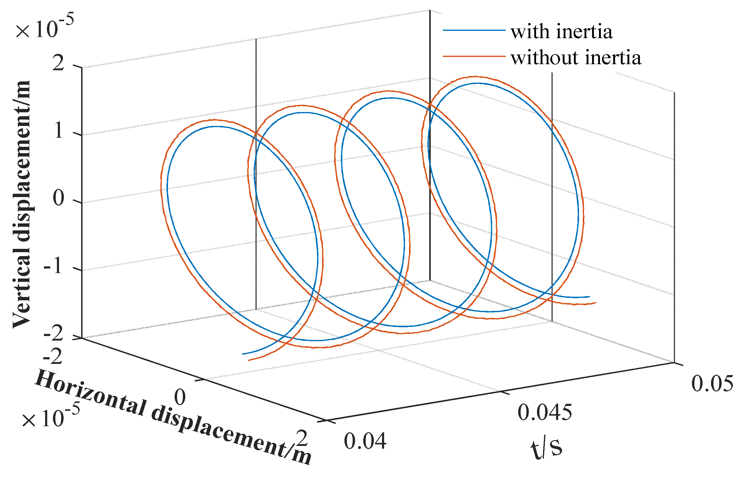
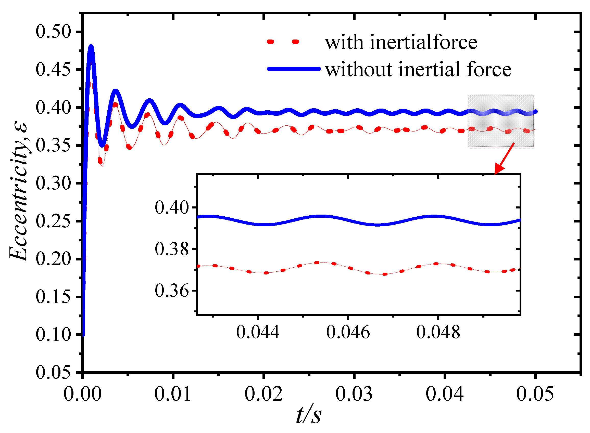
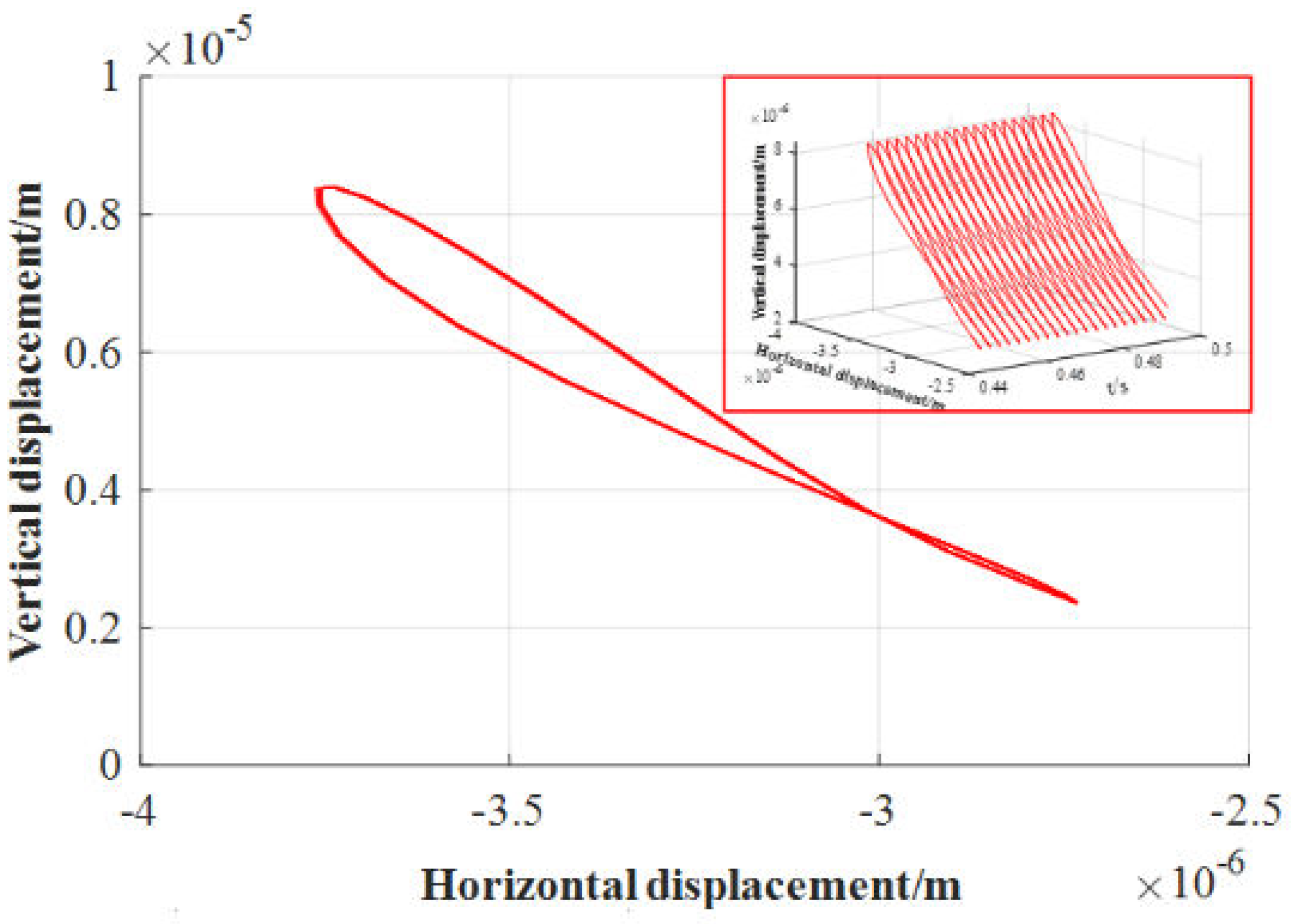
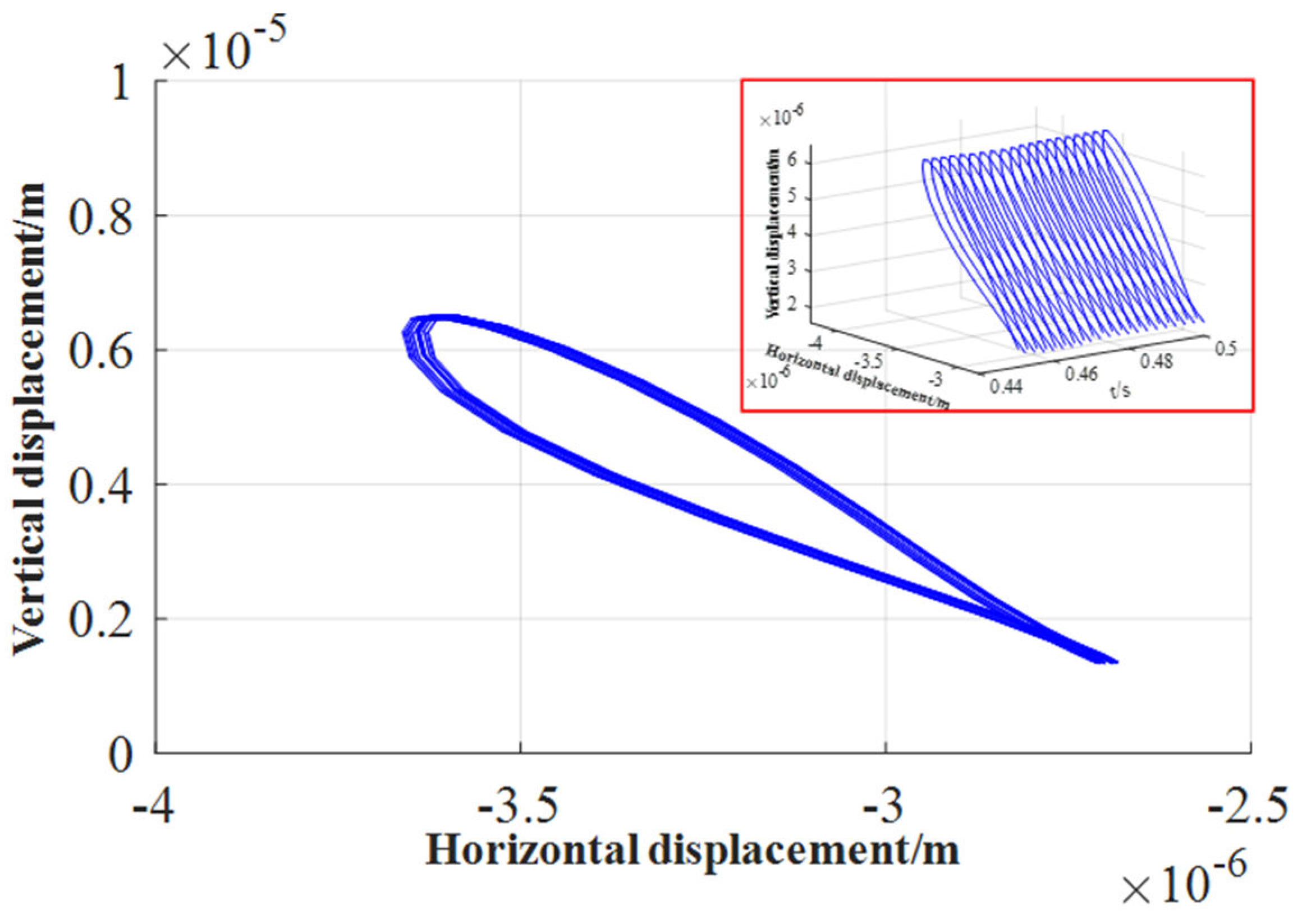
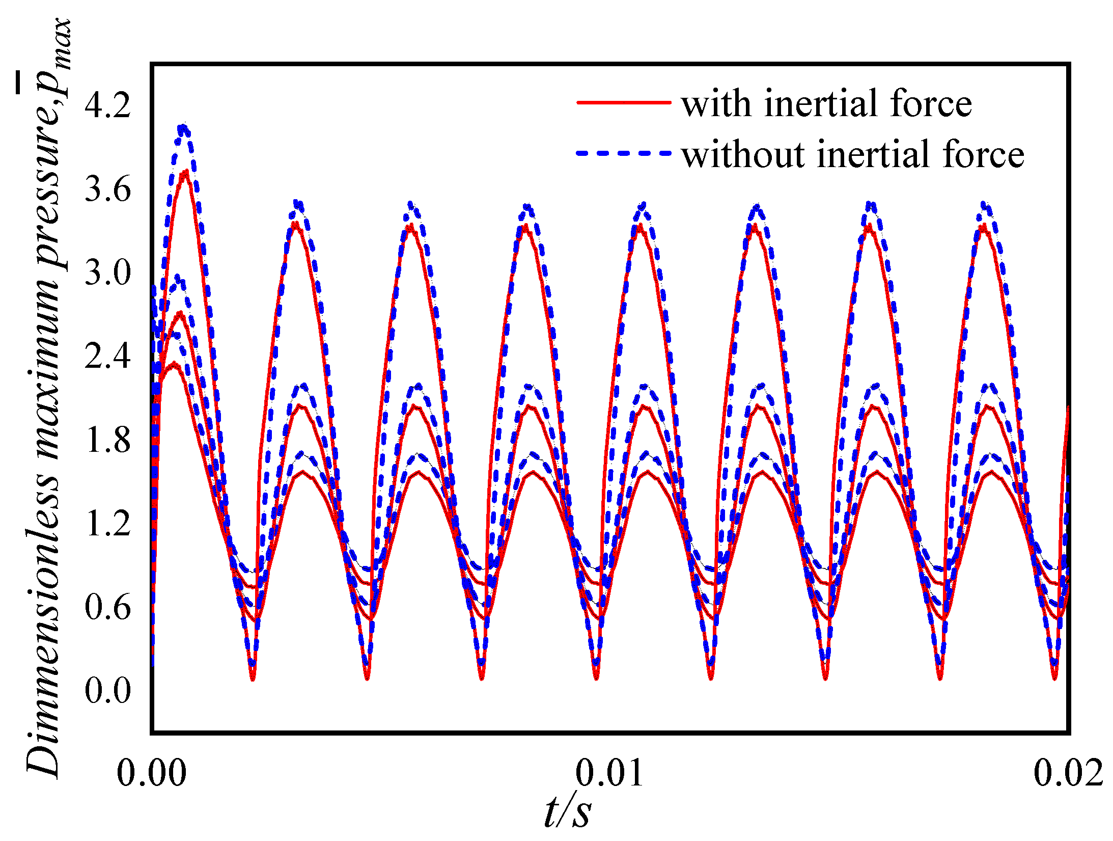
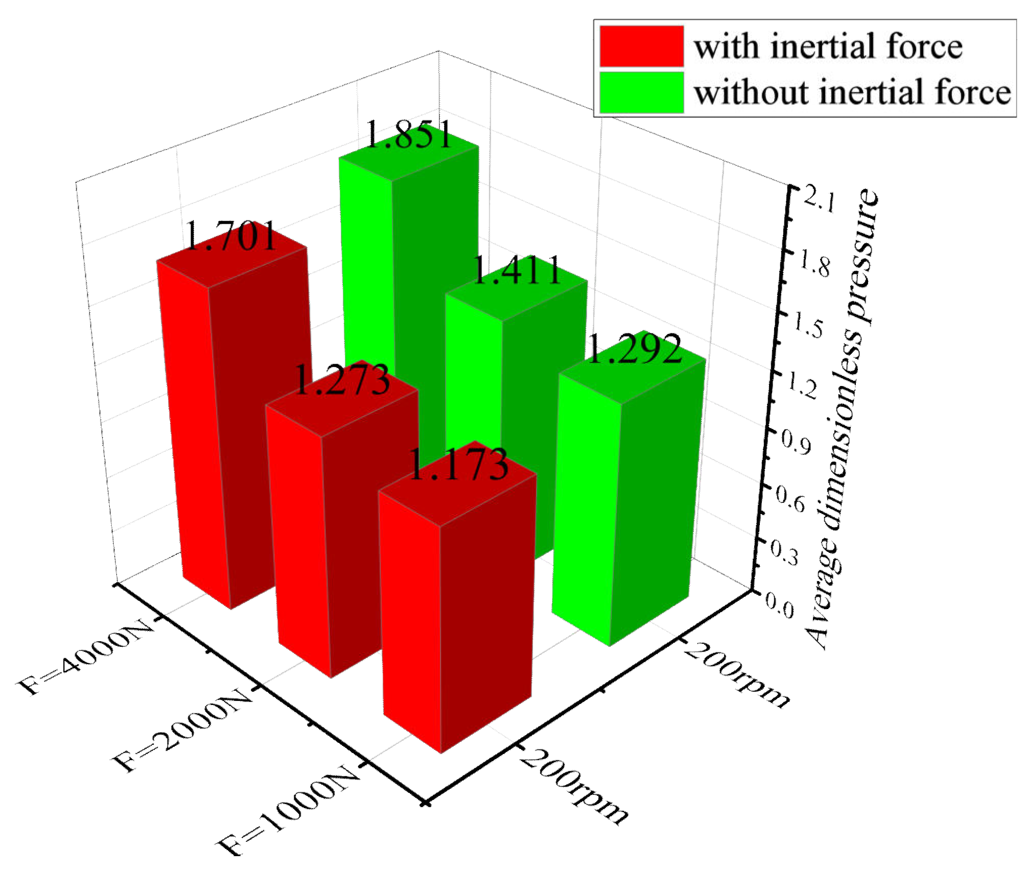
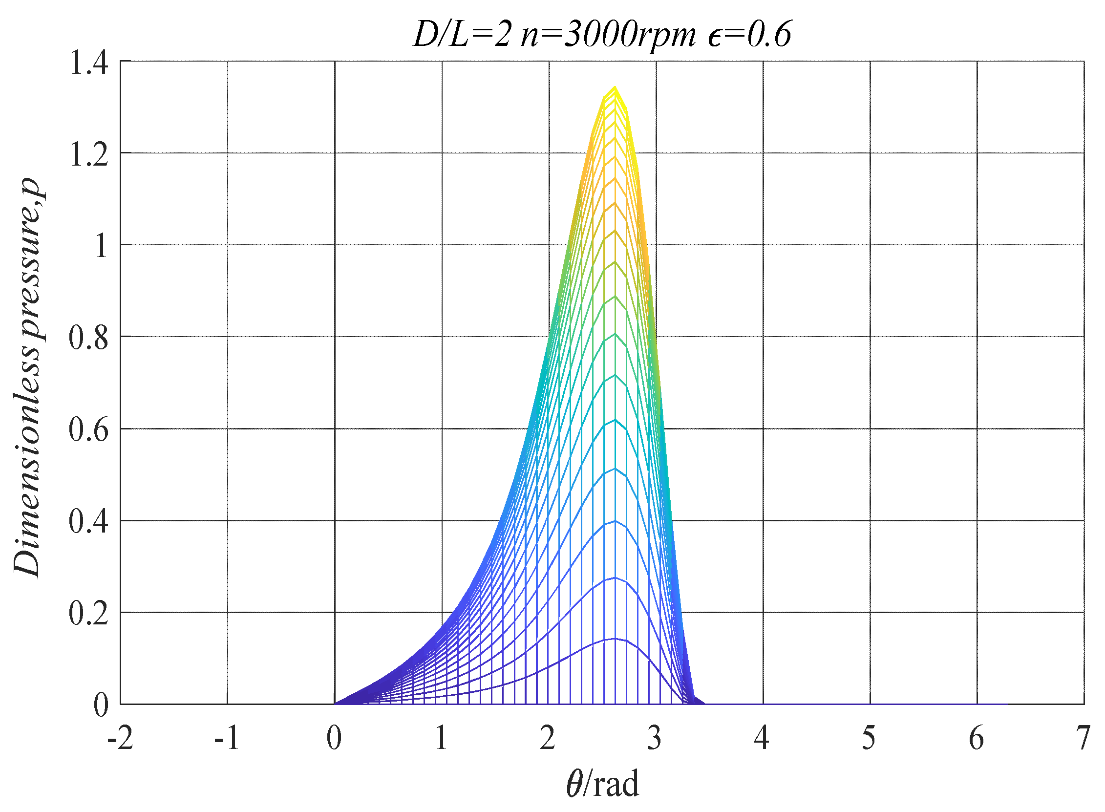
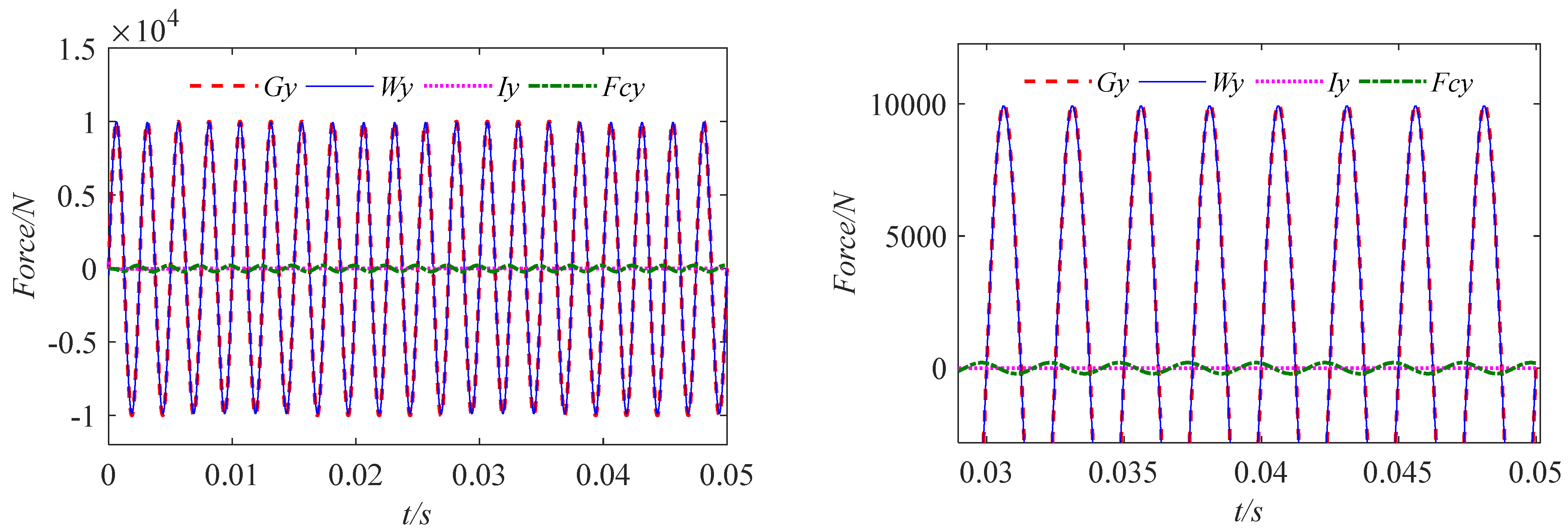
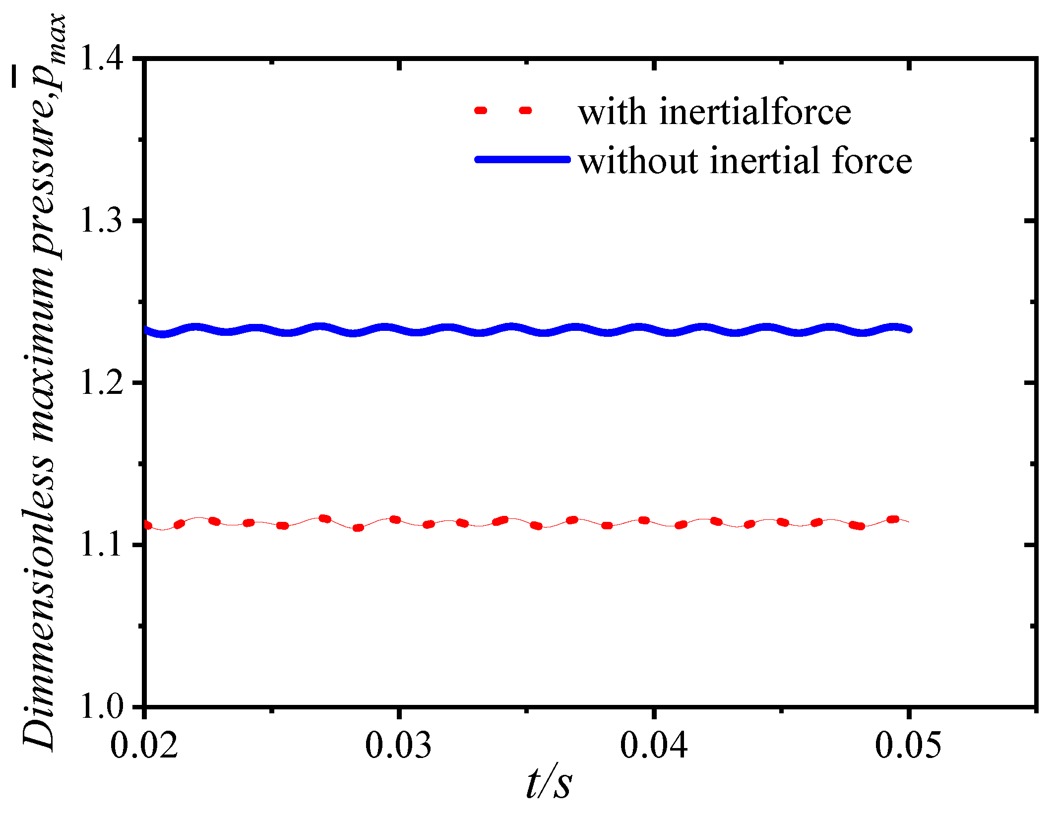
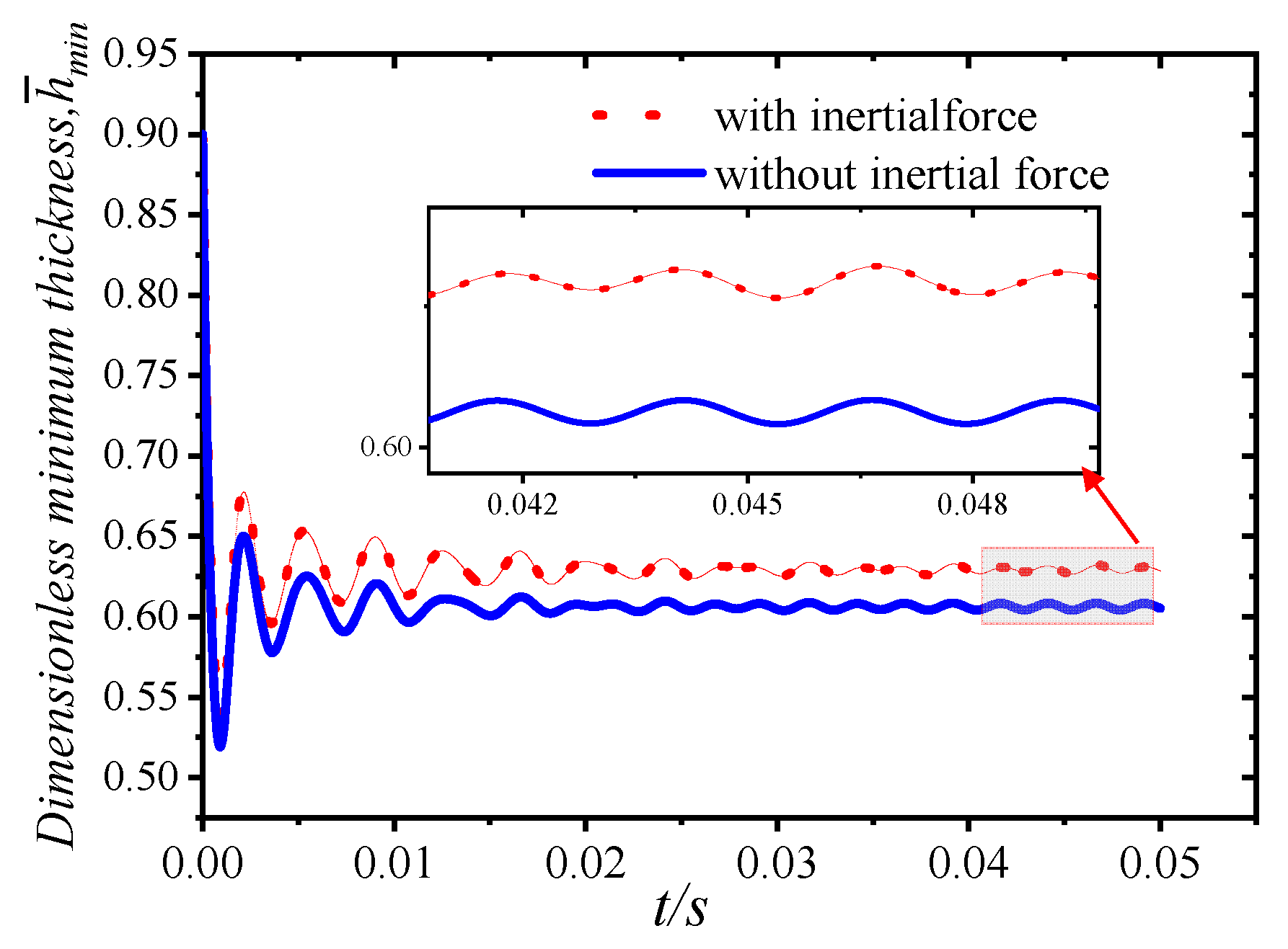
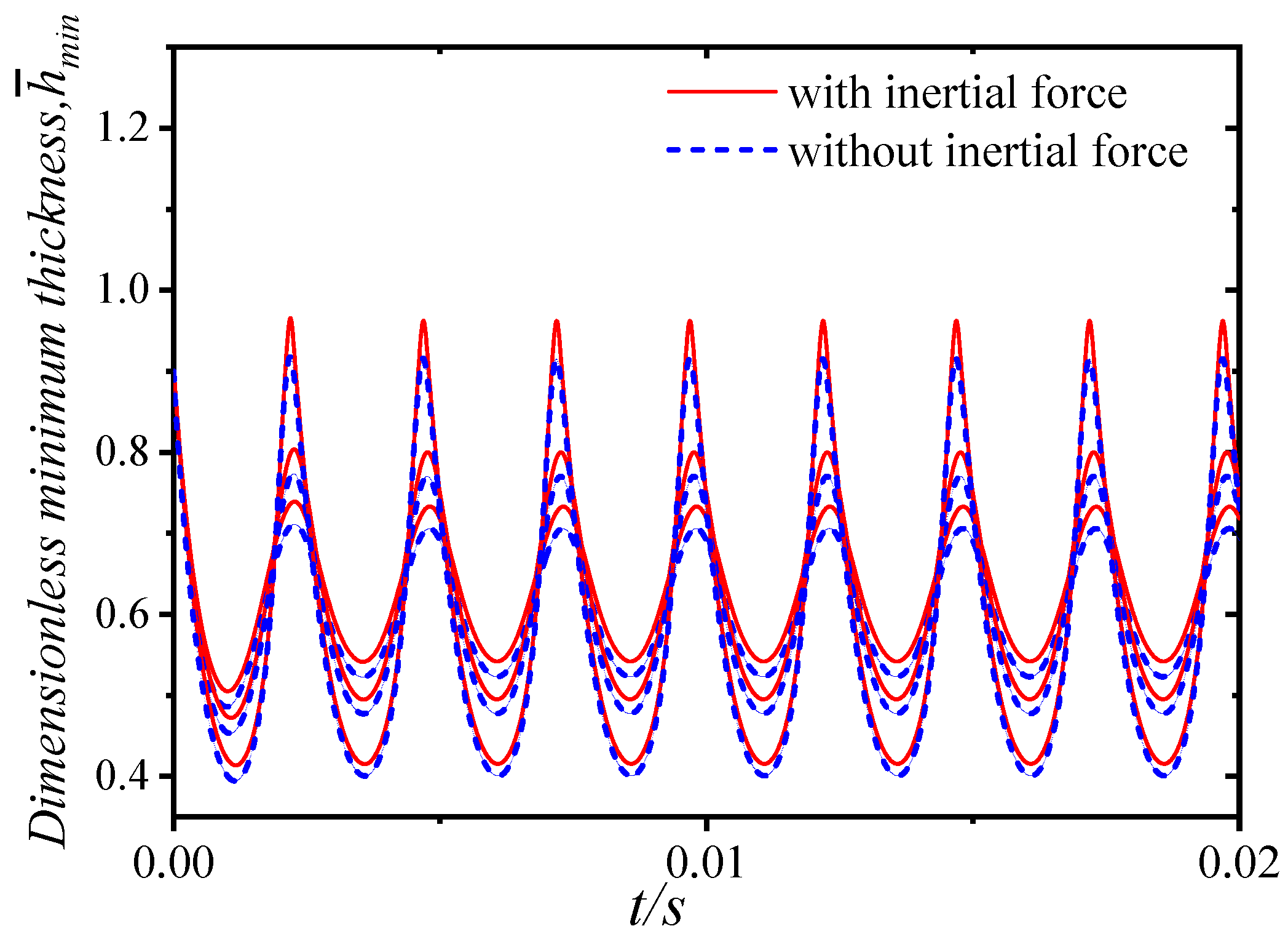
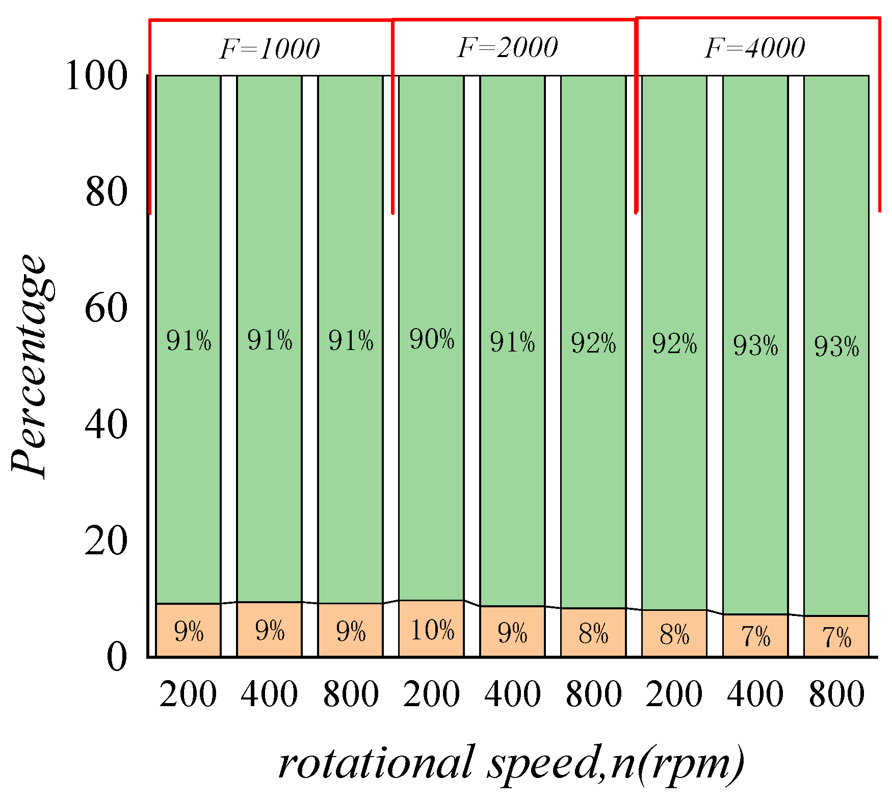
3.2. Effect of Inertial Force on Lubrication Characteristics

The effects of different loads, rotational speeds, and initial eccentricity on the time-domain lubrication characteristics of water-lubricated bearings with and without inertial force are studied in this paper.
The model parameters used in this paper are shown in Table 2. Considering the effect of sinusoidal periodic load, the load expression is  G x = 1.0 E 4 cos ( 800 π t ) G y = 1.0 E 4 sin ( 800 π t ) . The initial eccentricity  ε = 0.1 . The magnitude of this load remains the same, and the direction of the force changes at a frequency of 400 Hz .
Figure 10 and Figure 11 show the water film pressure space distribution and water film thickness distribution at a certain time when subjected to periodic external loads.
The three-dimensional distribution of the dimensionless water film pressure of the radial bearing is approximately a continuous parabolic distribution. In the interval where  0 θ 2 π , the dimensionless water film pressure increases to the maximum pressure value and then decreases. The peak value of the water film pressure at the peak and valley points of the selected load appears at  θ = 2.409 r a d = 138 o . The water film pressure peak at the zero point of the load appears at  θ = 2.304 r a d = 132 o . The water film pressure is concentrated in  0 θ π . There is a zero pressure zone in the region where  π θ 2 π because the journal has a rotating effect and a squeezing effect on the water film. In the circumferential direction, due to the rotation of the journal, the water is drawn into the convergent wedge of  0 θ π , and a positive pressure is generated due to the extrusion. However, within the divergence wedge of  π θ 2 π , the water is brought out, and a negative pressure area should be generated in theory. The liquid cannot bear the tensile stress, so the water film ruptures in the negative pressure area. Through numerical calculation, the boundary line of the non-zero pressure region can be accurately obtained, and the boundary line is near  θ = π . As can be seen from Figure 11, the thickness of the water film decreases continuously at first and reaches a minimum value when  θ = π .
The dynamic pressure lubrication state is the most ideal working state of the water-lubricated bearing. The lubrication characteristics of water-lubricated bearings depend not only on the selection of bearing materials and the design of structural parameters but also on the working conditions of the bearing during actual operation. When the load or rotational speed of the water-lubricated bearing changes, in order to meet the load-bearing requirements of the working condition, the eccentricity of the bearing will change accordingly. Therefore, the dynamic pressure lubrication characteristics of water-lubricated bearings are affected by the load, rotational speed, and eccentricity during operation.
The axial position of the bearing under a stable load is fixed in motion, and the thickness of the water film decreases with the increase in the load. The greater the load, the less reliable the bearing’s working stability and the more prone to failure. However, in the unsteady load bearing with changes in the magnitude and direction of the load, the position of the axis changes rapidly with time, forming a complex orbit of the journal center curve. For the study of journal orbits, using mobility and impedance methods is computationally less expensive than solving the Reynolds equation (Booker, 2014).
Keeping the journal rotation speed constant, we took the initial eccentricities as 0.1, 0.5, and 0.9, respectively, and investigated the effect of the initial eccentricity on the orbit of journal center. We drew the orbit of the journal center and the displacement time–history curves in the x and y directions, as shown in Figure 12, Figure 13, Figure 14, Figure 15, Figure 16 and Figure 17. It can be seen that the initial eccentricity set is different, which changes the initial position of the axis rotation. However, under the action of the circumferential sinusoidal periodic load, after the bearing rotates smoothly, the orbit of the journal center gradually converges to the center for a uniform circular motion. At the initial moment, due to the existence of the initial eccentricity, the axial displacement is disturbed. But after the external load and the water film force are balanced, the displacement in the x and y directions changes regularly and periodically. The displacement amplitude is the same, and the trajectory amplitude is about  3 × 10 5 m .
When the bearing rotates around the journal, there are inertial forces,  I x and  I y , caused by the acceleration of the journal; centripetal force,  F c , generated by uniform circular motion; and water film forces,  W x and  W y , in the x and y directions. These three forces are in balance with the external load under the superposition of the three forces. The three forces are decomposed along the x and y directions, and the time–history curve is shown in Figure 18 and Figure 19. It can be seen from the figure that the water film force, inertial force, and centripetal force all change periodically during the rotation of the bearing under the action of the circumferential external load. The main component in balance with the external load is the water film force, and the centripetal force and inertial force account for about 2%. When the rotation tends to be stable, the tangential and normal inertial forces almost disappear.
Under the premise of not changing the bearing size and speed, we set the initial eccentricity as  ε = 0.1 . In order to analyze the influence of inertial force on the dynamic characteristics of the bearing, the orbit of the journal center image, the dimensionless maximum water film pressure, the time–history curves of eccentricity, and the deflection angle are shown in Figure 20, Figure 21, Figure 22 and Figure 23. Under the circumferential external load, the inertial force had little influence on the axial trajectory. At the same speed, when the bearing rotation tends to stabilize, the shaft trajectory is slightly smaller than when the inertia force is not taken into account. Before the bearing motion is balanced, the convergence speed is faster when the inertial force of the journal is considered. The overall trend of changes in the time–history curves when the inertial force is considered are roughly the same. There is a large fluctuation at the initial unbalanced moment, and the value is smaller than that when the inertial force is not considered. When the rotation tends to be stable, the dimensionless water film force is small when the inertial force is considered. Comparing the time–history curves of the eccentricity and deflection angle, the difference is consistent with the water film pressure. However, the minimum water film thickness is relatively large.
Since the external load applied in the above example is a circumferential load, after the rotation approached a uniform circular motion, the tangential and normal inertial force components caused by the acceleration of the journal were very small. To continue analyzing the influence of inertial forces, the bearing size was not changed, and only a unidirectional load was applied. The load expression is  G y = 1.0 E 4 sin ( 80 π t ) , and the initial eccentricity is  ε = 0.1 . The rotational speeds were set to be 545.6 r/min, 1091.2 r/min, and 1636.8 r/min (the linear speeds are  2 m / s 4 m / s and  6 m / s , respectively) in order to study the influence of inertial forces at different speeds on the axis trajectory when unidirectional loads are applied. The results in 0.45 s–0.5 s are shown in Figure 24, Figure 25, Figure 26, Figure 27, Figure 28 and Figure 29. It can be seen that under the action of a one-way external load, with the increase in rotational speed, regardless of whether the inertial force is considered, the axis trajectory gradually diverges. At the same speed, when considering the journal inertial force, the axis trajectory is more convergent, mainly because the inertial force and the water film pressure participate in the balance of external load. When the inertial force is not considered, the water film force is directly balanced with the external load, resulting in divergence of the axis trajectory.
In fluid mechanics, the state of motion of a fluid is divided into a state of laminar motion and a state of turbulent motion. The Reynolds number  Re = ρ V h η 0 (which represents the ratio of inertial force to viscous force) is often used to characterize the state of motion of a fluid. In order to distinguish between these two states of motion, it is only necessary to find the critical Reynolds number that transitions between the two. The comparison of the Reynolds number and minimum thickness with different rotational speeds is shown in Figure 30. We can clearly see that with the increase in rotation speed, the trend of decreasing the minimum water film thickness shows clear linearity, and the growth trend of the Reynolds number gradually slows down. At the same speed, the difference between the thickness of the dimensionless minimum water film when considering and not considering the inertial force is basically unchanged, while the Reynolds number interpolation gradually increases.

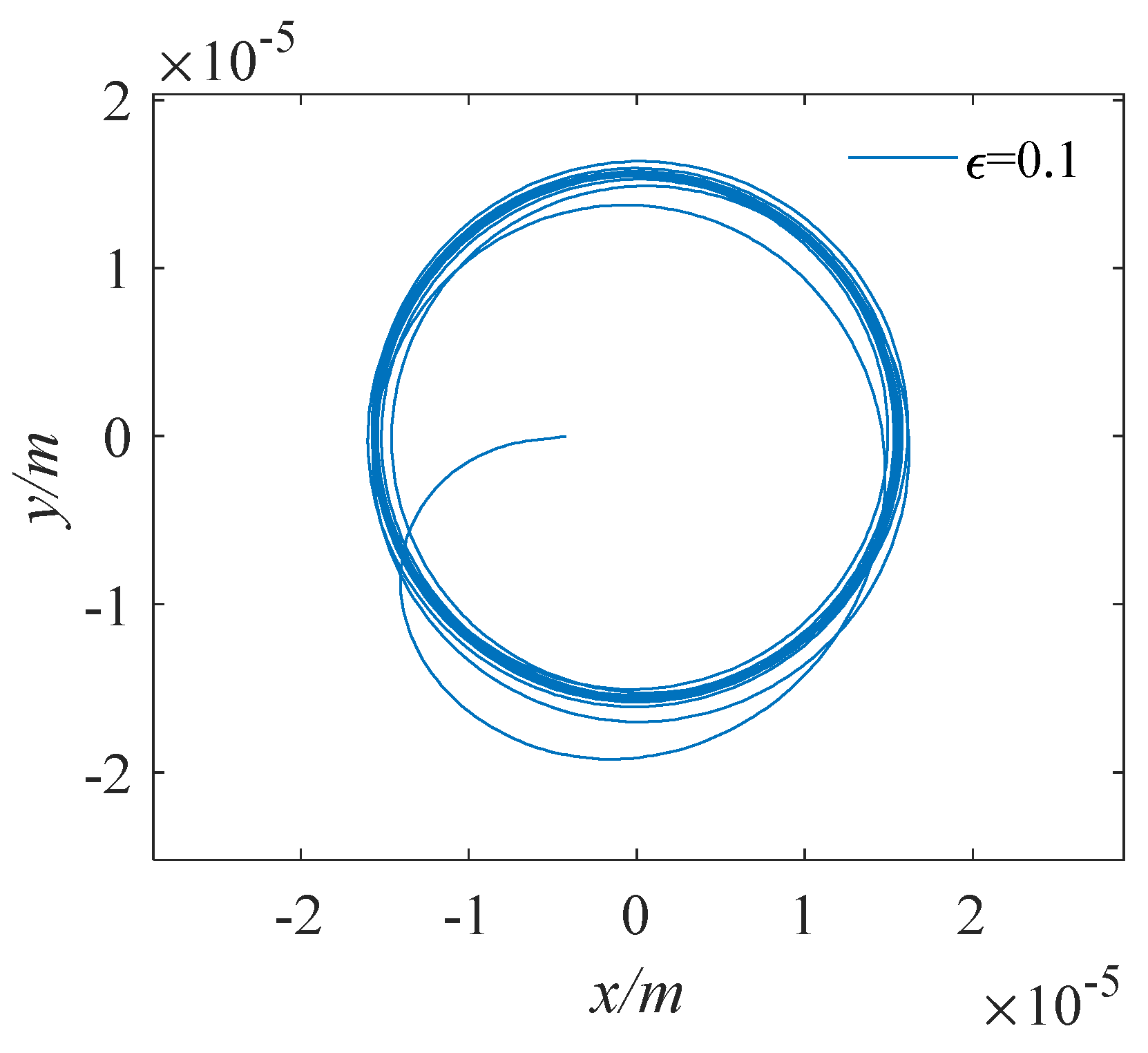
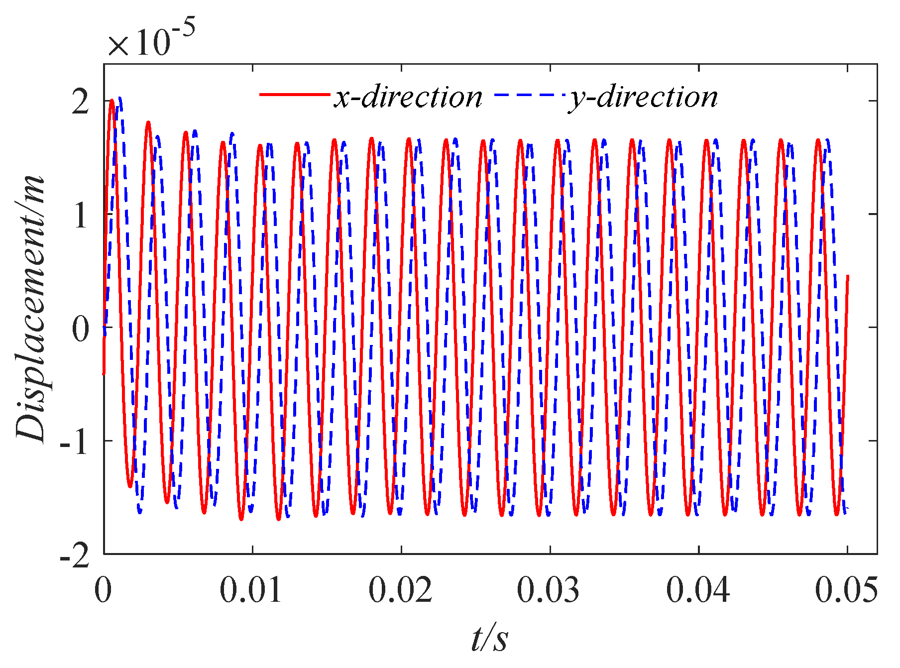
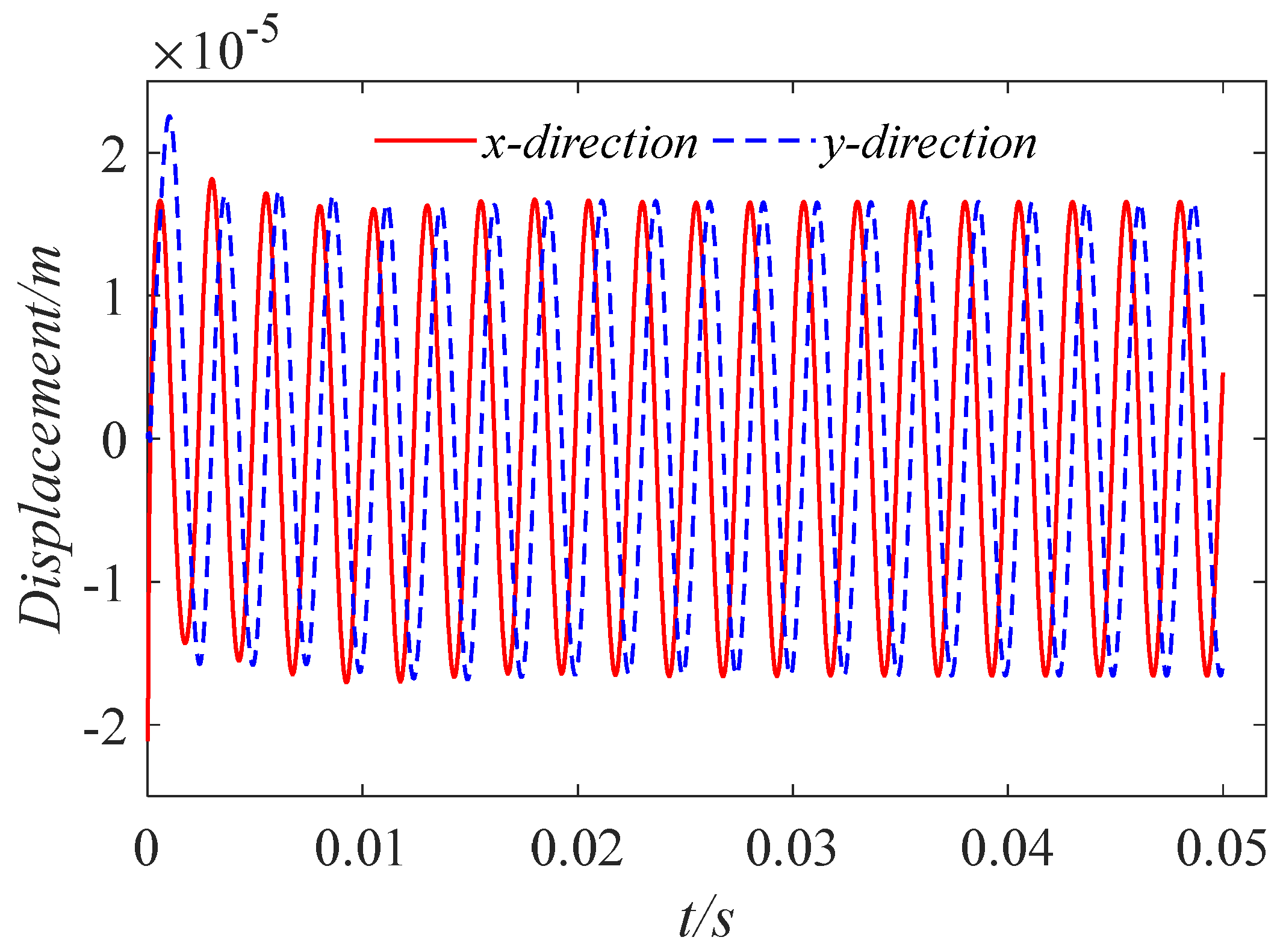
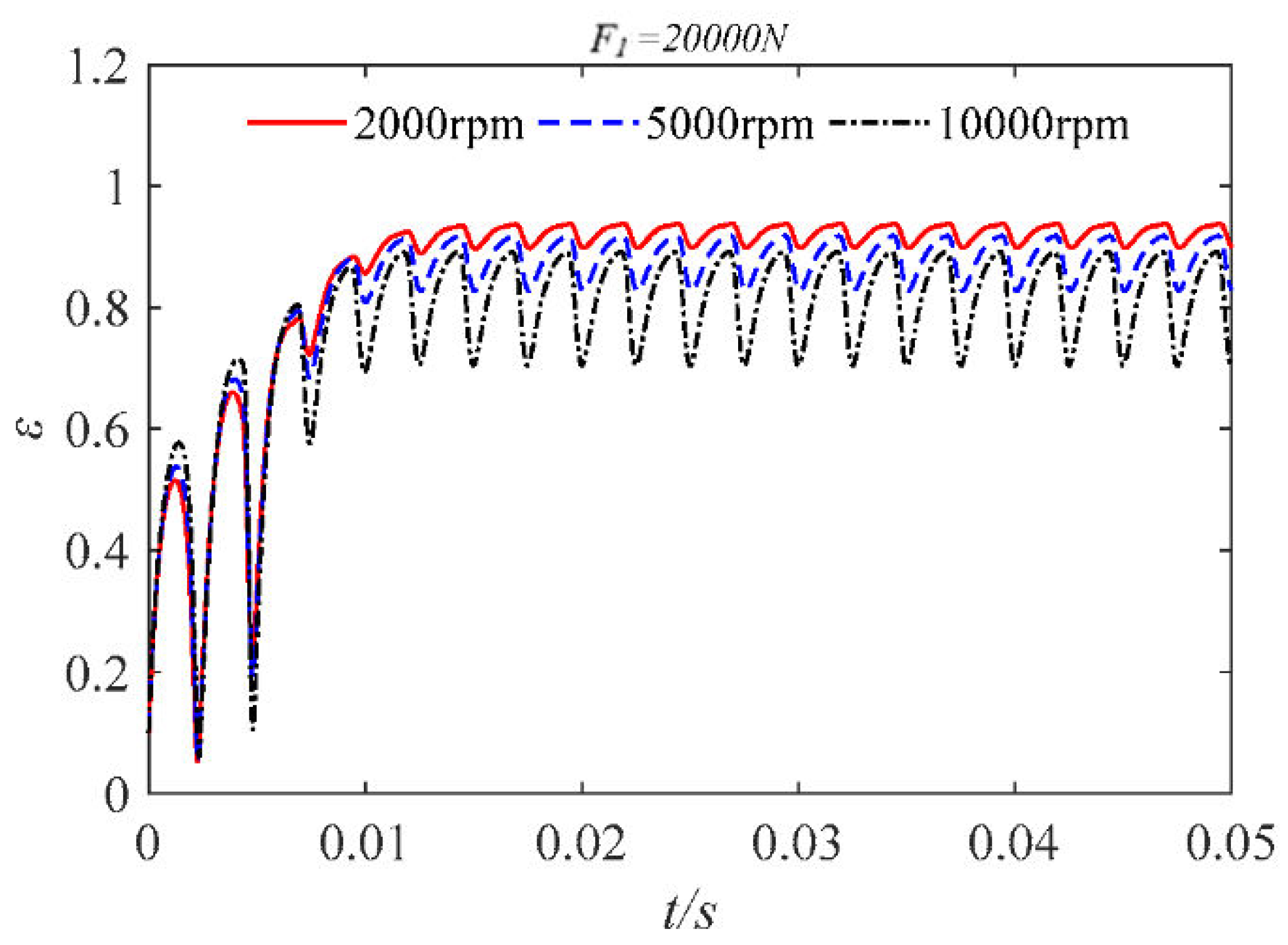
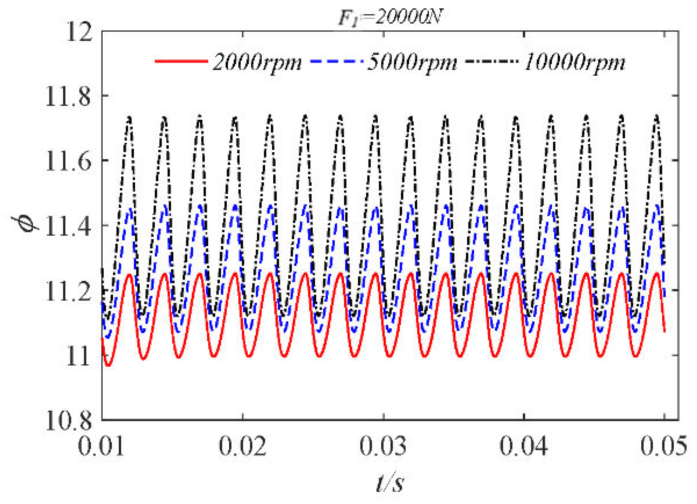
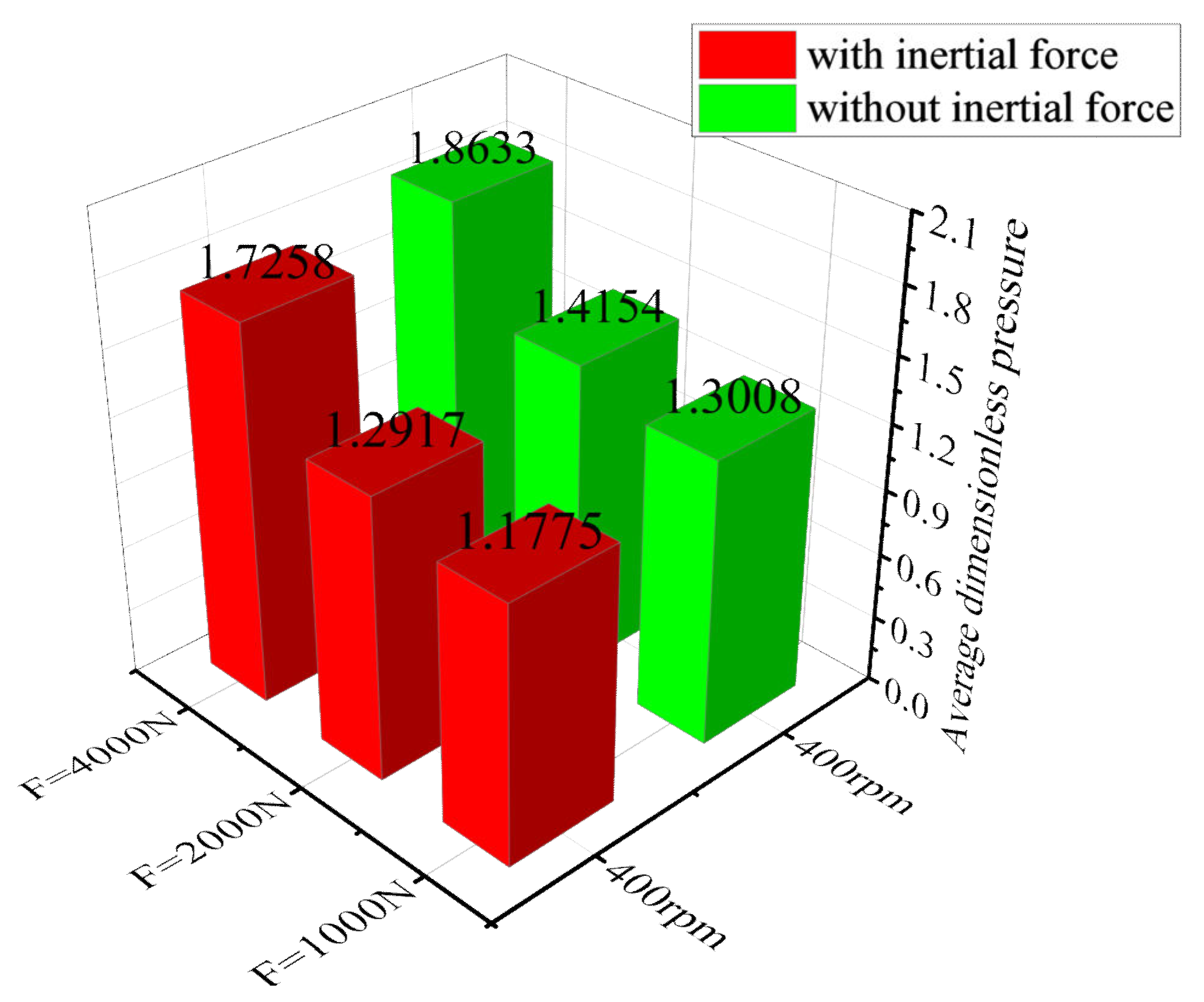
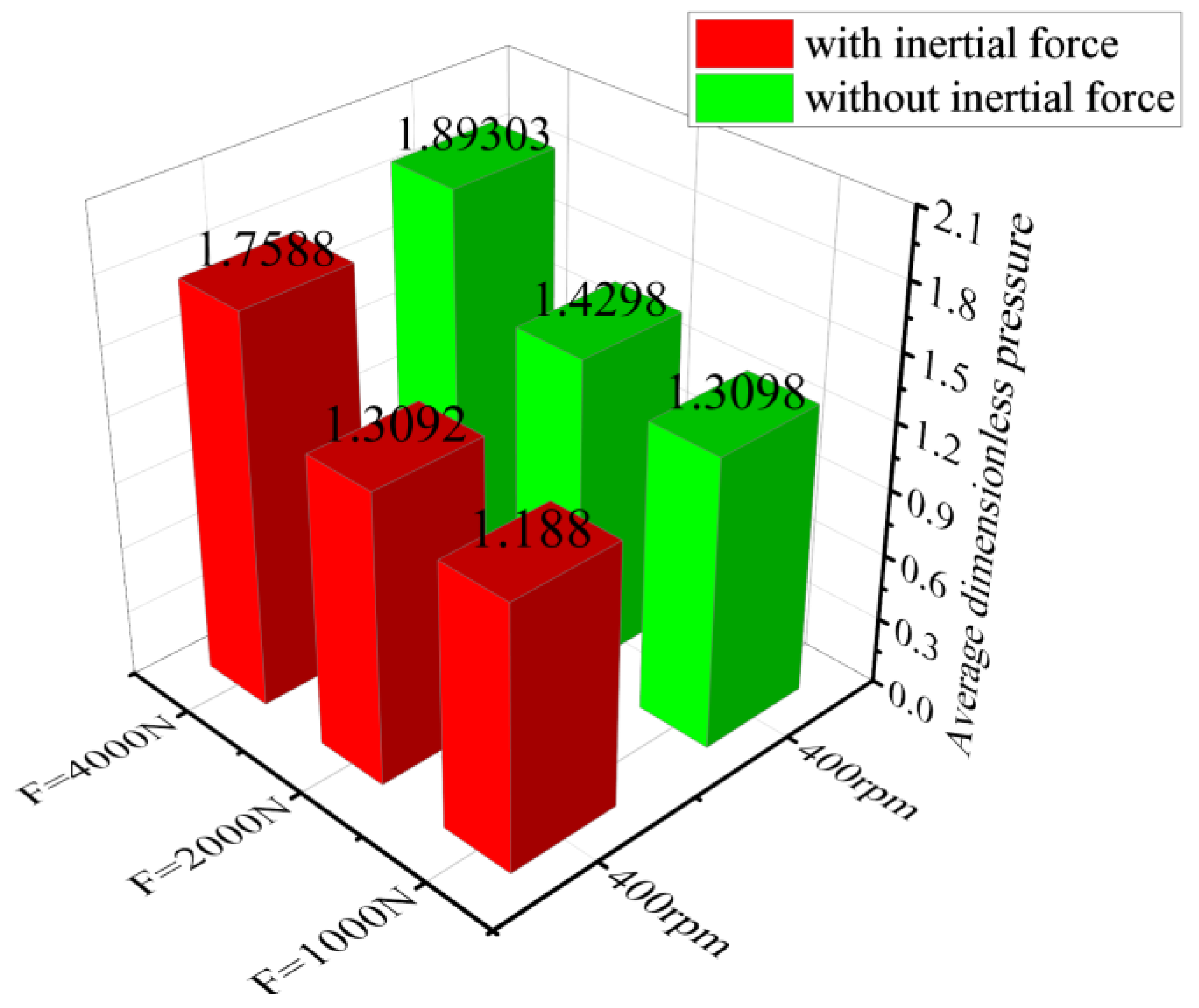
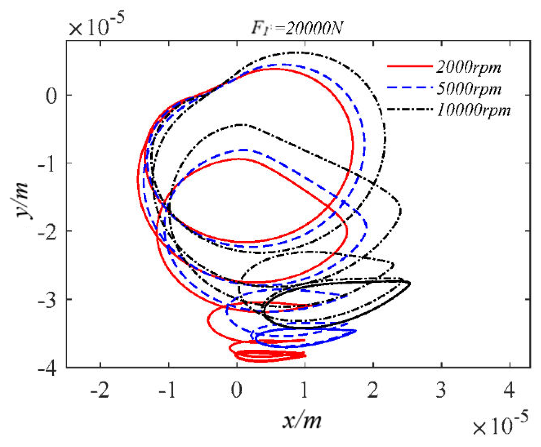
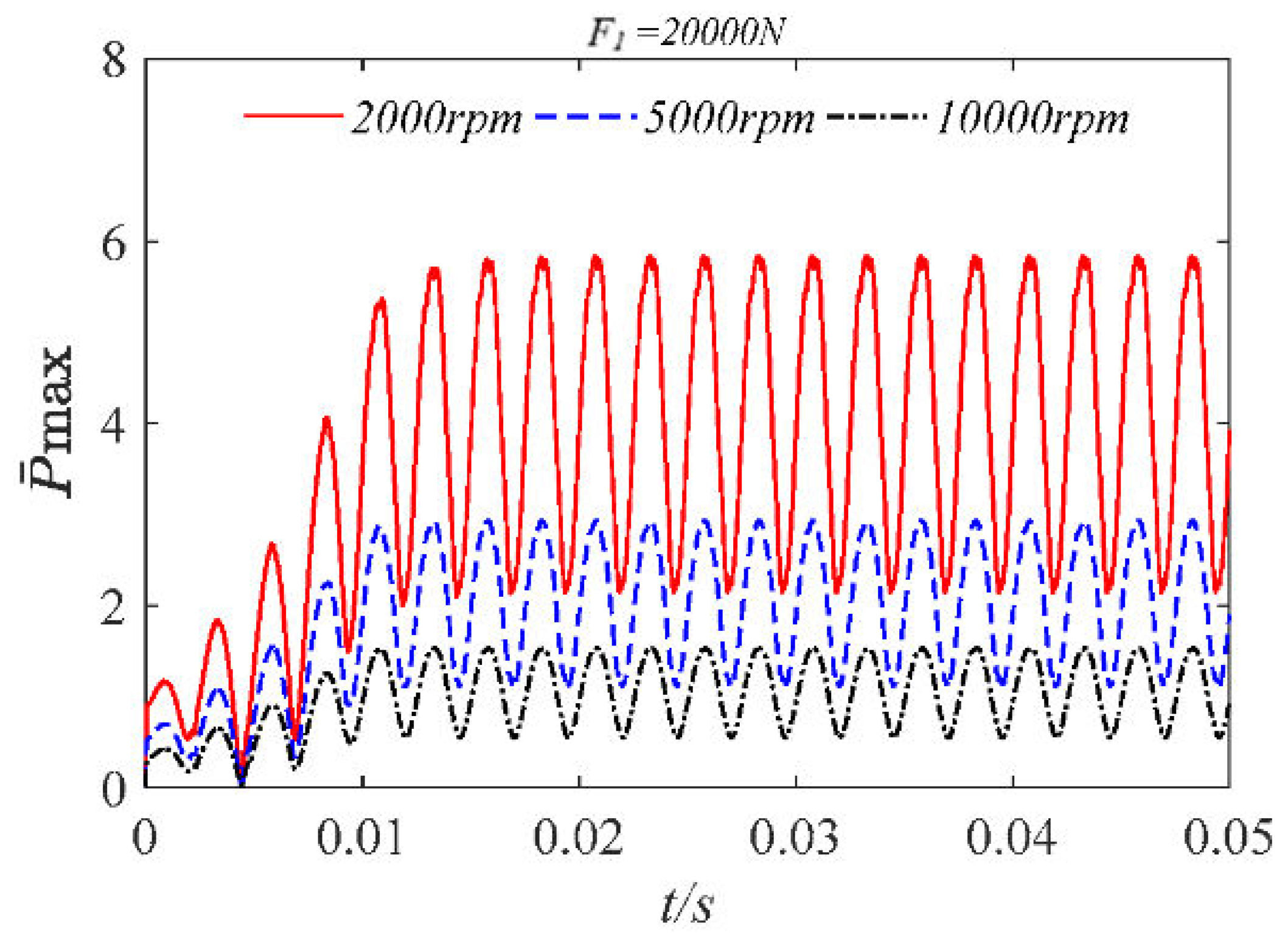
4. Analysis of Water Film Dynamic Characteristics under Low Speed and Heavy Load

In all kinds of mechanical equipment, many equipment failures are related to the running state of the bearing. According to statistics, in rotating machinery using bearings, about 30% of the failures are caused by the bearings. It can be seen that the quality of the bearings has a great influence on the working conditions of the machine. Bearings operate under long-term heavy load conditions, and various internal structures produce certain stress concentrations at stress points under long-term stress. If it is operated in such a state of stress concentration for a long time, the bearing stress point will be damaged or deformed to a certain extent, which will lead to the failure of the entire bearing component. Low-speed heavy-duty bearings bear larger loads, and it is more necessary to study the dynamic characteristics of water-lubricated low-speed heavy-duty bearings.
We applied a constant load,  F 1 , in the y direction while applying the load. The load was applied in a linear manner at first, and was fully applied after 0.1 s.
The constant load was applied as:
G x = 1.0 E 4 cos ( 800 π t ) G y = 1.0 E 4 sin ( 800 π t ) + F 1 m = { 100 t ( t 0.01 s ) 1 ( t > 0.01 s )
We set the rotational speed to 200 r/min, 400 r/min, and 800 r/min, while the constant load was  F 1 = 1000 N , 2000 N , 4000 N , respectively. Taking the calculation result of the speed of 200 as an example, Figure 31 and Figure 32 show the time–calendar curves of the dimensionless maximum pressure and minimum film thickness, respectively. When a constant load is applied, the time calendar of pressure and film thickness also shows strong periodicity. With the increase in constant load, the water film pressure is the opposite trend to the film thickness. In order to analyze the proportion of inertial force, the average water film pressure of nine groups of working conditions after the combination of three speeds and three loads was counted, as shown in Figure 33, Figure 34 and Figure 35. From the figure, it can be observed that the increase in speed and external load leads to an increase in pressure, and the pressure of the water film is relatively small when considering the inertial force. Figure 36 shows the proportion of inertial force obtained after statistics. From the figure, it can be observed that the increase in speed and external load leads to an increase in pressure, and the pressure of the water film is relatively small when considering the inertial force. Figure 36 shows the proportion of inertial force obtained after statistics. When the constant load remains unchanged, the increase in speed leads to an increase in the inertial force, and at the same speed, the increase in the external load will also lead to an increase in the inertial force, but the proportion of inertial force in the total pressure will decrease.
We set the static load amplitude to 20,000 N and compared the dynamic characteristics at different speeds when inertial force is considered, as shown in Figure 37, Figure 38, Figure 39 and Figure 40.
As shown in the figure, when the bearing is subjected to a large static load, the orbit of the journal center is elliptical. The increase in rotational speed causes the orbit of the journal center to diverge. The decrease in rotational speed leads to an increase in the peak pressure of the dimensionless maximum water film. After increasing the static load, the eccentricity fluctuates significantly during its application. When the rotation of the bearing tends to be stable, the higher the bearing speed, the greater the range of eccentricity changes. The reason for this phenomenon is that when the static load is large, the higher speed will cause the bearing to produce a larger centripetal force, which will produce large fluctuations during rotation, resulting in the magnitude of the eccentricity change.

5. Conclusions

In this paper, the Reynolds equation for the incompressible water-lubricated motion of the bearing and the force balance equation considering the inertial force of the shaft diameter have been established. Based on the finite difference method, the water film force distribution, eccentricity time–history curve, and orbit of the journal center of the bearing under static load and sinusoidal periodic load have been calculated. At the same time, the influence of rotational speed and external load on inertial force has been studied. Through the analysis of the obtained calculated data, the following conclusions are drawn:
(1) By analyzing the water film pressure distribution curve, it was obtained that the circumferential water film pressure first increases and then decreases, and reaches the maximum value at a certain point, showing nonlinearity. In practical situations, if water or oil is selected as the lubricant, a negative pressure area will be generated after positive pressure, and the liquid film cannot withstand too much negative pressure and rupture. The axial water film pressure is parabolically distributed, possibly due to the leakage of water from both ends of the bearing as the bearing rotates.
(2) Although the bearing capacity of the water-lubricated bearing is low, it can run at a lower speed when subjected to a constant amplitude circumferential load and when the boundary line of the non-zero pressure region of the water film is near  θ = π . For the application of periodic loads, when considering the inertial force, the axial trajectory is more convergent, the water film pressure is smaller than the eccentricity, and the thickness of the water film is larger, which means that the load-carrying capacity of the water-lubricated bearing is greater when the inertial force is considered.
(3) At the same time, the increase in speed and external load will lead to an increase in inertial force, but the increase in external load will lead to a decrease in the proportion of inertial force. Increasing the bearing speed is conducive to improving the bearing performance of water-lubricated bearings.
(4) In addition to the periodic external load in the circumferential direction, applying a constant load will cause the trajectory of the water-lubricated bearing to deviate. Considering the inertial force of the shaft diameter, the variation range of the eccentricity becomes larger, and the maximum pressure of the water film also becomes larger. In the calculation of low-speed heavy load in this paper, the speed range is between 200 r/min and 800 r/min, and the pressure of the dimensionless water film caused by inertial force is reduced by 7 to 10 percent, which means that the influence of inertia force cannot be ignored, and the lubrication performance of the bearing can be evaluated more accurately considering the inertia force.

Author Contributions

Conceptualization, S.S.; methodology, C.L. and S.S.; software, F.J.; validation, C.L., F.J. and S.S.; formal analysis, C.L. and F.J.; data curation, F.J.; writing—original draft preparation, C.L. and F.J.; writing—review and editing, C.L.; visualization, F.J. and L.Q.; supervision, M.Z.; project administration, C.S.; funding acquisition, S.S., M.Z. and L.Q. All authors have read and agreed to the published version of the manuscript.

Funding

This work is supported by the Excellent Youth Project of Heilongjiang Natural Science Foundation (YQ2019E010), the National Natural Science Foundation of China (Grant Nos. 12172338 and 51909246), and the Natural Science Foundation of Jiangsu Province of China (Grant No. BK20220044).

Data Availability Statement

The data used to support the findings of this study are available from the corresponding author upon request.

Conflicts of Interest

The authors declare no conflict of interest.

Nomenclature

εEccentricity ratio
DBearing diameter, m D = 2R
dJournal diameter, m d = 2r
LBearing width, m
  ϕ Attitude angle
  ω Angular velocity, rad
cRadial clearance, m
hWater film thickness, m
ρDensity of liquid phase.
eEccentricity, m
η0Viscosity of water, Pa·s
u, vx, y direction displacement, m
nRotate speed, rpm
  G x , G y x, y direction external load, N
MMass of the journal, kg
pPressure, Pa
vPoisson’s ratio
  k x x , k x y , k y x , k y y Stiffness factor
  c x x , c x y , c y x , c y y Damping factor
  I x , I y Inertial forces, N
  F c Centripetal force, N
  Re I , Re J Reynolds number
  θ , z Circumference, axial direction
  ξ , η Radial, tangential direction
  i , j Circumference, axial node

References

  1. Xie, Z.L.; Jiao, J.; Yang, K. A state-of-art review on the water-lubricated bearing. Tribol. Int. 2023, 180, 108276. [Google Scholar] [CrossRef]
  2. Mallya, R.; Shenoy, S.B.; Pai, R. Steady state characteristics of misaligned multiple axial groove water-lubricated journal bearing. J. Eng. Tribol. 2015, 229, 712–722. [Google Scholar] [CrossRef]
  3. Lin, C.G.; Yang, Y.N.; Chu, J.L.; Sima, C.; Liu, P.; Qi, L.B.; Zou, M.S. Study on nonlinear dynamic characteristics of propulsion shafting under friction contact of stern bearings. Tribol. Int. 2023, 183, 108391. [Google Scholar] [CrossRef]
  4. Cai, J.L.; Xiang, G.; Li, S. Mathematical modeling for nonlinear dynamic mixed friction behaviors of novel coupled bearing lubricated with low viscosity fluid. Phys. Fluids 2022, 34, 093612. [Google Scholar] [CrossRef]
  5. Lin, C.G.; Zou, M.S.; Sima, C.; Liu, S.X.; Jiang, L.W. Friction-induced vibration and noise of marine stern tube bearings considering perturbations of the stochastic rough surface. Tribol. Int. 2019, 131, 661–671. [Google Scholar] [CrossRef]
  6. Zhang, X.; Wang, X.R.; Niu, G.L.; Zhang, L.J. The Research Actuality and Development Trends of Water Lubricated Bearings. Equip. Manuf. Technol. 2008, 1, 101–102. [Google Scholar]
  7. Xie, Z.L.; Jiao, J.; Yang, K. Theoretical and experimental study on the fluid-structure-acoustic coupling dynamics of a new water lubricated bearing. Tribol. Int. 2023, 177, 107982. [Google Scholar] [CrossRef]
  8. Zou, M.S.; Tang, H.C.; Liu, S.X. Modeling and calculation of acoustic radiation of underwater stiffened cylindrical shells treated with local damping. Mar. Struct. 2023, 88, 103366. [Google Scholar] [CrossRef]
  9. Xie, Z.L.; Jiao, J.; Wrona, S. The fluid-structure interaction lubrication performances of a novel bearing: Experimental and numerical study. Tribol. Int. 2023, 179, 108151. [Google Scholar] [CrossRef]
  10. Wang, J.G.; Zhou, J.Z.; Dong, D.W.; Yan, B.; Huang, C.R. Nonlinear dynamic analysis of a rub-impact rotor supported by oil film bearings. Arch. Appl. Mech. 2012, 83, 413–430. [Google Scholar] [CrossRef]
  11. Brown, R.D.; Addison, P.; Chan, A.H.C. Chaos in the unbalance response of journal bearings. Nonlinear Dyn. 1994, 5, 421–432. [Google Scholar] [CrossRef]
  12. Jing, J.P.; Meng, G.; Sun, Y.; Xia, S.B. On the non-linear dynamic behavior of a rotor-bearing system. J. Sound Vib. 2004, 274, 1031–1044. [Google Scholar] [CrossRef]
  13. Brancati, R.; Rocca, E.; Russo, M.; Russo, R. Journal orbits and their stability for rigid unbalanced rotors. J. Tribol. 1995, 117, 709–716. [Google Scholar] [CrossRef]
  14. Brancati, R.; Russo, M.; Russo, R. On the stability of periodic motions of an unbalanced rigid rotor on lubricated journal bearings. Nonlinear Dyn. 1996, 10, 175–185. [Google Scholar] [CrossRef]
  15. Li, D.X.; Xu, J.X. A method to determine the periodic solution of the non-linear dynamics system. J. Sound Vib. 2004, 275, 1–16. [Google Scholar] [CrossRef]
  16. Lin, C.G.; Zou, M.S.; Sima, C.; Qi, L.B.; Yu, Y. Non-Linear coupled dynamics of a flexible propeller-shaft system supported by water film bearings. J. Vib. Acoust. 2020, 142, 031008. [Google Scholar] [CrossRef]
  17. Sun, W.P.; Yan, Z.M.; Tan, T.; Zhao, D.L.; Luo, X.Q. Nonlinear characterization of the rotor-bearing system with the oil-film and unbalance forces considering the effect of the oil-film temperature. Nonlinear Dyn. 2018, 92, 1119–1145. [Google Scholar] [CrossRef]
  18. Cai, J.L.; Han, Y.F.; Xiang, G.; Wang, J.X.; Wang, L.W. Effects of wear and shaft-shape error defects on the tribo-dynamic response of water-lubricated bearings under propeller disturbance. Phys. Fluids 2022, 34, 077118. [Google Scholar] [CrossRef]
  19. Singh, U.; Roy, L.; Sahu, M. Steady-state thermo-hydrodynamic analysis of cylindrical fluid film journal bearing with an axial groove. Tribol. Int. 2008, 13, 1135–1144. [Google Scholar] [CrossRef]
  20. Kornaeva, E.; Kornaev, A.; Savin, L.; Galichev, A.; Babin, A. Theoretical premises of a vibro-inertial method of viscosity measurement. Vibroengineering Procedia 2016, 8, 440–445. [Google Scholar]
  21. Xie, Z.L.; Ta, N.; Rao, Z.S. The lubrication performance of water lubricated bearing with consideration of wall slip and inertial force. J. Hydrodyn. 2017, 29, 52–60. [Google Scholar] [CrossRef]
  22. Gao, G.Y.; Yin, Z.W.; Jiang, D.X.; Zhang, X.L. Numerical analysis of plain journal bearing under hydrodynamic lubrication by water. Tribol. Int. 2014, 75, 31–38. [Google Scholar] [CrossRef]
  23. Wang, Y.Z.; Yin, Z.W.; Jiang, D.; Gao, G.Y.; Zhang, X.L. Study of the lubrication performance of water-lubricated journal bearings with CFD and FSI method. Ind. Lubr. Tribol. 2016, 68, 341–348. [Google Scholar] [CrossRef]
  24. Wojciech, L. Influence of local bush wear on water lubricated sliding bearing load carrying capacity. Tribol. Int. 2016, 103, 352–358. [Google Scholar]
  25. Xiang, G.; Yang, T.Y.; Guo, J.; Wang, J.X. Optimization transient wear and contact performances of water-lubricated bearings under fluid-solid-thermal coupling condition using profile modification. Wear 2022, 502–503, 204379. [Google Scholar] [CrossRef]
  26. Sun, F.X.; Zhang, X.B.; Wei, Y.S.; Wang, X.; Wang, D. Stability analysis of rubber-supported thrust bearing in a rotor-bearing system used in marine thrusters under disturbing moments. Tribol. Int. 2020, 151, 106356. [Google Scholar] [CrossRef]
  27. Jakobsson, B. The finite journal bearing, considering vaporization. Trans. Chalmers Univ. Technol. 1957, 190, 1–116. [Google Scholar]
  28. Zhang, Z.M. Theory of Hydrodynamic Lubrication of Sliding Bearings; Higher Education Press: Beijing, China, 1986. [Google Scholar]
  29. Zhang, X.L.; Yin, Z.W.; Gao, G.Y.; Li, Z. Determination of stiffness coefficients of hydrodynamic water-lubricated plain journal bearings. Tribol. Int. 2015, 85, 37–47. [Google Scholar] [CrossRef]
  30. Booker, J.F. Mobility/impedance methods: A guide for application. J. Tribol. 2014, 136, 024501. [Google Scholar] [CrossRef]
Figure 1. Sketch map of hydrodynamic journal bearing geometry.
Lubricants 11 00145 g001
Figure 2. Dividing the water film.
Lubricants 11 00145 g002
Figure 3. Effect of radial and circumferential mesh numbers on pressure.
Lubricants 11 00145 g003
Figure 4. Comparison of eccentricity at different time steps.
Lubricants 11 00145 g004
Figure 5. Comparison of maximum pressure at different time steps.
Lubricants 11 00145 g005
Figure 6. Comparison of y direction displacement at different time steps.
Lubricants 11 00145 g006
Figure 7. Dimensionless pressure (p/p0) distribution at z = L/2 for D/L= 2, ε = 0.6.
Lubricants 11 00145 g007
Figure 8. Comparison of dimensionless pressure (p/p0) distribution at z = L/2 for D/L = 0.5, 1, and 2, ε = 0.6.
Lubricants 11 00145 g008
Figure 9. Finite bearing orbit plot.
Lubricants 11 00145 g009
Figure 10. Dimensionless water film pressure distribution (t = 0.00625 s).
Lubricants 11 00145 g010
Figure 11. Dimensionless water film thickness distribution (t = 0.00625 s).
Lubricants 11 00145 g011
Figure 12. Orbit of journal center (ε = 0.1).
Lubricants 11 00145 g012
Figure 13. Displacement in x, y direction (ε = 0.1).
Lubricants 11 00145 g013
Figure 14. Orbit of journal center (ε = 0.5).
Lubricants 11 00145 g014
Figure 15. Displacement in x, y direction (ε = 0.5).
Lubricants 11 00145 g015
Figure 16. Orbit of journal center (ε = 0.9).
Lubricants 11 00145 g016
Figure 17. Displacement in x, y direction (ε = 0.9).
Lubricants 11 00145 g017
Figure 18. Time–history curves of four forces in the x direction.
Lubricants 11 00145 g018
Figure 19. Time–history curves of four forces in the y direction.
Lubricants 11 00145 g019
Figure 20. Comparison of orbits of journal center with and without inertia force.
Lubricants 11 00145 g020
Figure 21. Comparison of dimensionless maximum water film pressure with and without inertia force.
Lubricants 11 00145 g021
Figure 22. Comparison of eccentricity time–history curve with and without inertia force.
Lubricants 11 00145 g022
Figure 23. Comparison of deflection angle time–history curves with and without inertia force.
Lubricants 11 00145 g023
Figure 24. Orbit of journal center (with inertial force, n = 545.6 r/min).
Lubricants 11 00145 g024
Figure 25. Orbit of journal center (without inertial force, n = 545.6 r/min).
Lubricants 11 00145 g025
Figure 26. Orbit of journal center (with inertial force, n = 1091.2 r/min).
Lubricants 11 00145 g026
Figure 27. Orbit of journal center (without inertial force, n = 1091.2 r/min).
Lubricants 11 00145 g027
Figure 28. Orbit of journal center (with inertial force, n = 1636.8 r/min).
Lubricants 11 00145 g028
Figure 29. Orbit of journal center (without inertial force, n = 1636.8 r/min).
Lubricants 11 00145 g029
Figure 30. Comparison of Reynolds number and minimum thickness.
Lubricants 11 00145 g030
Figure 31. Dimensionless maximum water film pressure (n = 200 r/min, F1 = 1000, 2000, 4000 N).
Lubricants 11 00145 g031
Figure 32. Dimensionless minimum water film thickness (n = 200 r/min, F1 = 1000, 2000, 4000 N).
Lubricants 11 00145 g032
Figure 33. Dimensionless average water film pressure (n = 200 r/min, F1 = 1000, 2000, 4000 N).
Lubricants 11 00145 g033
Figure 34. Dimensionless average water film pressure (n = 400 r/min, F1 = 1000, 2000, 4000 N).
Lubricants 11 00145 g034
Figure 35. Dimensionless average water film pressure (n = 800 r/min, F1 = 1000, 2000, 4000 N).
Lubricants 11 00145 g035
Figure 36. The proportion of inertial force.
Lubricants 11 00145 g036
Figure 37. Orbits of journal center at different speeds.
Lubricants 11 00145 g037
Figure 38. Dimensionless maximum water film pressures at different speeds.
Lubricants 11 00145 g038
Figure 39. Eccentricity time–history curves at different speeds.
Lubricants 11 00145 g039
Figure 40. Deflection angle time–history curves at different speeds.
Lubricants 11 00145 g040
Table 1. Parameters of the simulation by Zhang et al. [28] and Zhang et al. [29].
ParametersValue
Bearing radius, R40 mm
Bearing width80 mm
Bearing clearance, c0.04 mm
Rotate speed, r/min,3000
Table 2. Parameters of the numerical simulation.
ParametersValue
Bearing radius, R35.05 mm
Bearing width, L70.09 mm
Bearing clearance, c0.0845 mm
Rotate speed, n545.6 r/min
Viscosity of water, η00.001103 Pa·s
The density of water, ρ1000 kg/m3
Disclaimer/Publisher’s Note: The statements, opinions and data contained in all publications are solely those of the individual author(s) and contributor(s) and not of MDPI and/or the editor(s). MDPI and/or the editor(s) disclaim responsibility for any injury to people or property resulting from any ideas, methods, instructions or products referred to in the content.

