Article

Tribological Behaviour and Microstructure of an Aluminium Alloy-Based g-SiC Hybrid Surface Composite Produced by FSP

Centre for Advanced Mechanical and Green Technology (SIG: Machine Design and Tribology), Faculty of Engineering and Technology, Multimedia University, Jalan Ayer Keroh Lama, Melaka 75450, Malaysia
*
Author to whom correspondence should be addressed.
Lubricants 2023, 11(3), 124; https://doi.org/10.3390/lubricants11030124
Submission received: 29 January 2023 / Revised: 19 February 2023 / Accepted: 21 February 2023 / Published: 10 March 2023
(This article belongs to the Special Issue Advances in Surface Engineering and Tribology)

Abstract

:
In this work, the microstructure and wear characteristics of a surface-reinforced composite based on an aluminium alloy with a mixture of graphene nanoplatelets (GNP) and silicon carbide (SiC), referred to as g-SiC, fabricated by Friction Stir Processing (FSP), are investigated. To further improve the tribological performance, different volume fractions (0 vol%, 5 vol%, 10 vol% and 15 vol%) of g-SiC-reinforced aluminium alloy are prepared by FSP. It is concluded that the Friction Stir Processed (FSPed) AA5083/g-SiC (15 vol%) specimen has optimum reduction in average friction coefficient (61.13%) and optimum reduction in specimen weight (72.97%). In summary, such hybrid reinforcements effectively improve the mechanical and tribological properties of metals with minimal negative impact on the environment and humans, while reducing material loss and overall manufacturing costs.

1. Introduction

Frictional wear and tear ought to shorten lifespan and reduce efficiency of mechanical systems [1]. Hence, the effort of advancing material properties with various reinforcements is initiated apart from the study of lubrication [2]. Metals with enhanced material properties are known as metal matrix composite (MMC), which focuses on reinforcing bulk metals with selected reinforcements [3]. However, multiple mechanical properties enhancements are impossible to achieve throughout the metal including the surface [3]. Thus, in this work, aluminium is selected in producing surface-reinforced composite and enhanced on the surface layer while retaining its original bulk material properties. Such selection of base metal ought to be outstanding since aluminium is utilized in a wide range of applications due to its excellent strength-to-weight ratio compared to other metals [4]. The focused application in this study is the journal bearing of a steam turbine, since it requires high corrosion resistance due to the encountered steam precipitate during operation [5] with excellent mechanical properties in prolonging the lifespan of the bearing. Moreover, the surface reinforcement is beneficial in this selected application since lubricating film tends to be destroyed due to the direct metal-to-metal contact within the journal bearing, especially during frequent start–stop operation [6]. It thus validates the importance of such reinforcement in maintaining efficient and low operating cost by reducing the overall maintenance cost.
Apart from the selected base metal and application, the reinforcement route is also crucial in producing the desired surface-reinforced metal composite. Friction Stir Processing (FSP) is known as one of the effective and energy-efficient routes in producing surface-reinforced composite via severe plastic deformation (SPD) technique [7]. Such a route is preferred in this work based on the Green Tribology concept since it is eco-friendly in producing the surface-reinforced composite. This is because the key in modifying the microstructure of involving a base metal with reinforcements throughout FSP is solely relying on the generated frictional heat [8].
From the perspective of reinforcements’ selections, ceramic additive-like silicon carbide (SiC) is generally treated as the reinforcement for surface-reinforced composite due to exceptional mechanical properties and chemical stability, which can be purchased cheaply [9]. However, the protrusion of ceramic particles under continuous wear is the limitation for such surface composite since it can cause unwanted wear on unreinforced counterparts [10]. Thus, the involvement of another reinforcement is required to overcome the hardship faced by ceramic reinforced surface metal composite.
Graphene is commonly utilized as a solid lubricant due to its unique self-lubricating properties [11]. Graphene nanoplatelets (GNP) is selected in this work compared to other graphene allotropes due to its multilayer stack-like structure in large surface area with minimum structural defects compared to graphene oxide (GO) and reduced graphene oxide (rGO) [12,13], contributing to lower friction coefficient (COF) by restraining microstructural motion [14]. Generally, the involvement of GNP in this study aims to overcome the disadvantage encountered by ceramic reinforced surface metal composite since it is commonly reported that the graphene film contributes a self-lubricating feature with low coefficient of friction (COF) and frictional heat generated at the surface contact surfaces [15]. Such GNP involvement also aims to reduce the frequent usage of commercial lubricants, which may cause pollution during the disposal process [16] to further achieve eco-friendliness within the community.
Thus, in this work, the hybrid reinforcement, g-SiC, is applied in producing the surface-reinforced composite via FSP. Surface-reinforced composite with different g-SiC volume fraction (0 vol%–15 vol%) is prepared to study its effect on mechanical and tribological properties’ enhancements. The friction and wear properties exhibited by each prepared Friction Stir Processed (FSPed) specimen is studied via pin-on-ring tribo-tester (POR) and compared with as-received base metal and solely SiC reinforced specimen.

2. Materials and Methods

2.1. Base Metal Selection

Aluminium alloy 5083 (AA5083-H112) is chosen as the base metal, which is obtained from Lian Giap & Co. (Hardware) Sdn. Bhd, Kuala Lumpur, Malaysia. Breakdown of AA5083-H112 chemical composition as provided by the manufacturer is shown in Table 1. The procured AA5083-H112 has the dimensions of 177 mm (length), 36 mm (width), and 25.4 mm (height).

2.2. Reinforcements’ Preparations

The required SiC and GNP for hybrid reinforcements’ preparations were purchased from Sigma Aldrich and GO advanced Solutions Sdn. Bhd., Kuala Lumpur, Malaysia, respectively. Dry mixing technique is implemented after both of the involving reinforcements are weighed using the Setra EL-410S weighing balance and prepared in the ratio of 60:40 (SiC:GNP) according to the desired volume fractions. The rule of mixture stated in Equation (1) is applied since it is suitable for powder mixing between hybrid mixtures in dry state [17]. The general density formula stated in Equation (2) is then applied to obtain the actual mass of GNP and SiC needed according to the pre-set g-SiC volume fractions.
ρ g S i C = ρ G N P × w f G N P + ρ S i C × w f S i C  
where, ρGNP and ρSiC are the density of GNP and SiC, respectively, while wfGNP and wfSiC are the weight fraction of GNP and SiC, respectively.
M a s s   o f   g-SiC   g = ρ g S i C × v  
where, ρg-SiC is the overall density of the g-SiC hybrid mixtures while v is the volume of the machined groove for powder insertion.
The mixed powder is observed under a Meiji MT-7530 metallurgical microscope (Meiji Techno, Miyoshi, Saitama, Japan) to ensure that the mixing outcome is homogenous before proceeding with the powder insertion process within the machined groove, as shown in Figure 1.

2.3. Specimens’ Preparations

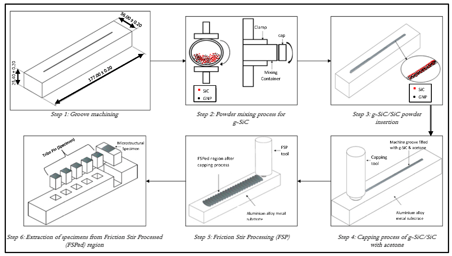
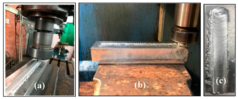
The process overview for specimens’ preparations is displayed in Figure 2. The capping process is initiated via milling machine by Pao Fong Industry Co., Ltd. once the mixed powder mentioned in Section 2.2 is inserted within the machined groove in AA5083-H112 samples. Such process is to encapsulate the reinforcements within the base metal before FSP as a prevention to powder spilling using a pin-less capping tool [18]. FSP is then initiated on the capped samples via the usage of CNC milling machine by Technology Park Malaysia Corp. and a tapered threaded pin profile FSP tool, as shown in Figure 3. Spindle speed of 2200 rpm, feed rate of 25 mm/min, and plunge depth of 0.5 mm are set to be the standardized process parameters throughout the FSP, which is based on the research outcomes by Sharma et al. [19].

2.4. Microstructural Analysis

The extraction process of specimens from the FSPed samples is carried out at the center of the stir zone (SZ), as illustrated in Figure 4. Microstructural specimens and tribo pins are the core specimens required in this work for microstructural analysis and friction and wear tests, respectively. The engineering drawing and actual outcomes of the extraction process for both specimens are shown in Figure 5 and Figure 6, respectively.
The extracted microstructural specimens are resumed for three different processes known as grinding, polishing, and etching before observing under Meiji MT-7530 metallurgical microscope (Meiji Techno, Miyoshi, Saitama, Japan). Grinding and polishing processes carried out using Metkon Forcipol 2V Grinder and Polisher (Metkon Instruments Inc, Bursa, Turkey) while the actual microstructure of the specimens can only be revealed after the etching process via the application of Keller’s Reagent [20]. The surface condition after each process is presented in Figure 7.

2.5. Microhardness Tests

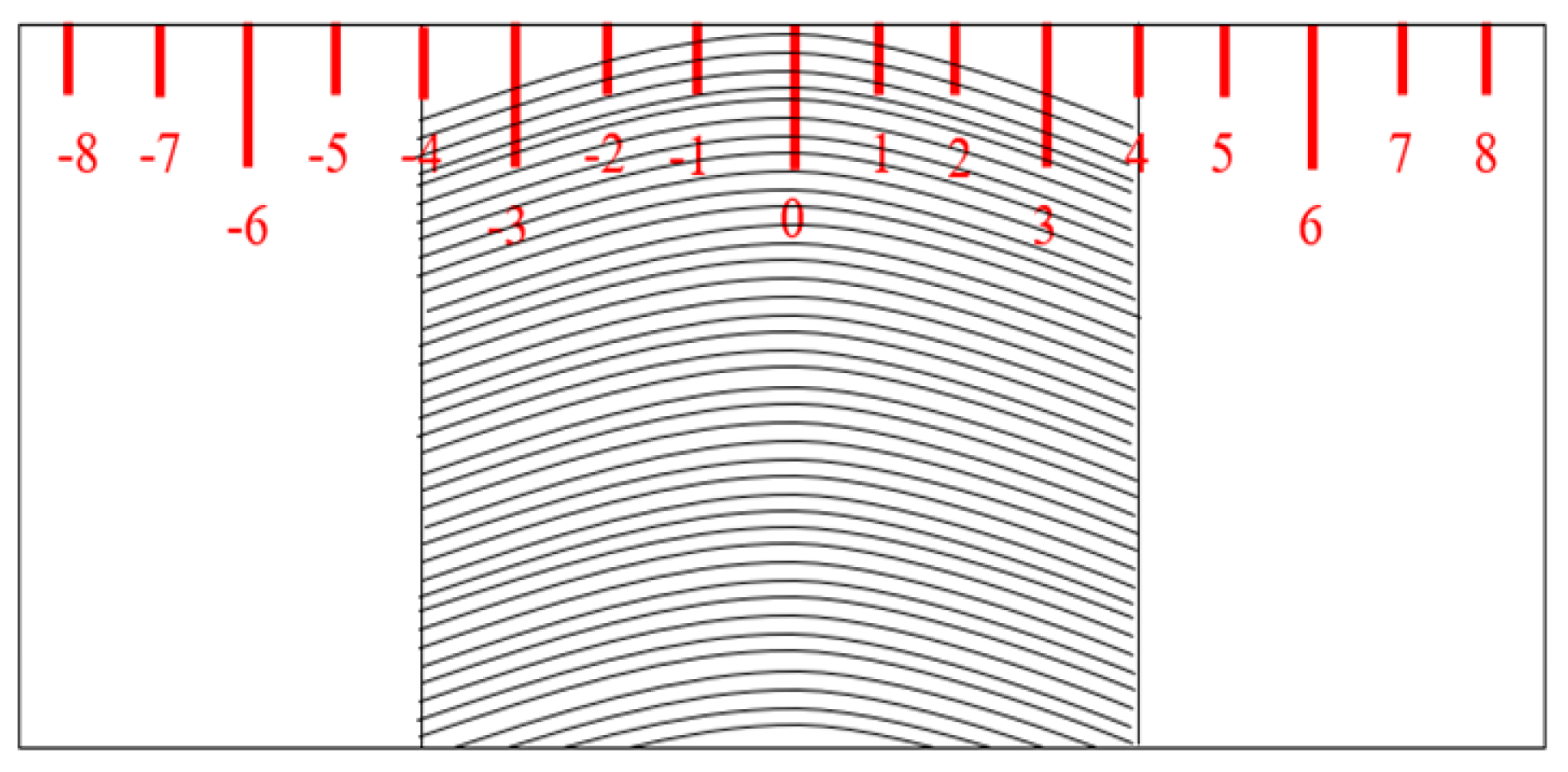
The Vickers hardness tester (Model: 452 SVD) (Wolpert Wilson Instruments, Pfungstadt, Hesse, Germany) is utilized to measure the microhardness of each microstructural specimen with different variations under the pre-set compression load of 9.81 N in this work. Each microstructural specimen is initially labelled with numberings from point −8 to point 8 (seventeen markings in total) starting from one end until another end of each specimen, as illustrated in Figure 8. Each marking has a 2 mm gap, which is treated as the markings for microhardness testing. Note that the stir zone (SZ) is within the region labelled from −4 to 4. Such pre-setting is to ensure that the microhardness measurement is taken under consideration for discussion throughout this work.

2.6. Friction and Wear Tests

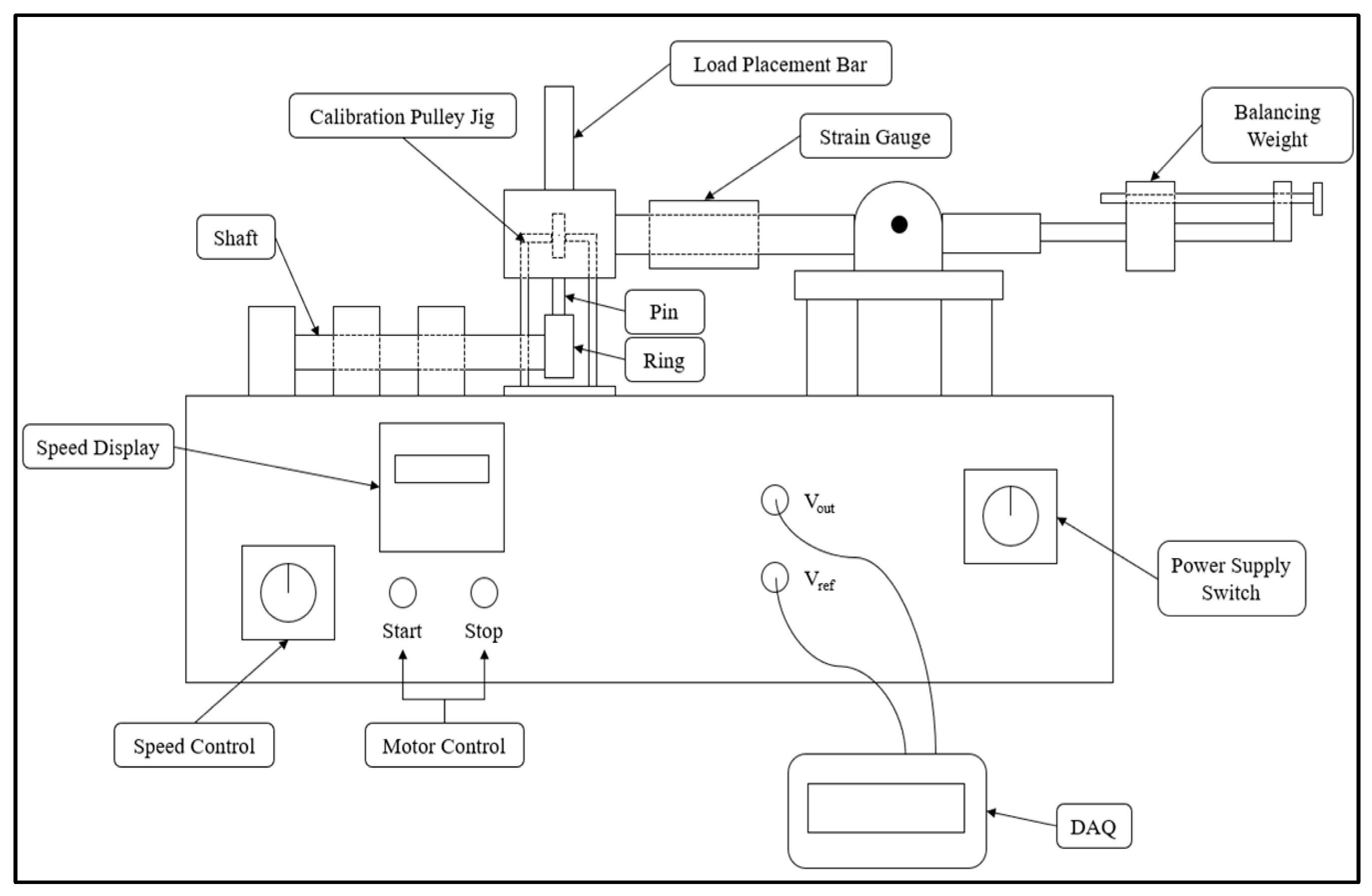
FSPed samples undergo the specimens’ extraction process for two different types of specimens, which are known as the tribo pins and the microstructural specimens. The mentioned extraction process is carried out at the middle of the stir zone (SZ) to determine the overall performance of the FSPed specimens since the significant enhancement occurs within SZ [21]. In this work, the friction and wear tests are carried out using the pin-on-ring tribo-tester with its setup and schematic diagram shown in Figure 9. The tribological standards from ASTM G77–G98 are applied throughout the tests. Stainless steel 304 (SS 304) is selected as the counter-ring material with a dimension of 40 mm inner diameter, 60 mm outer diameter and 10 mm thickness.
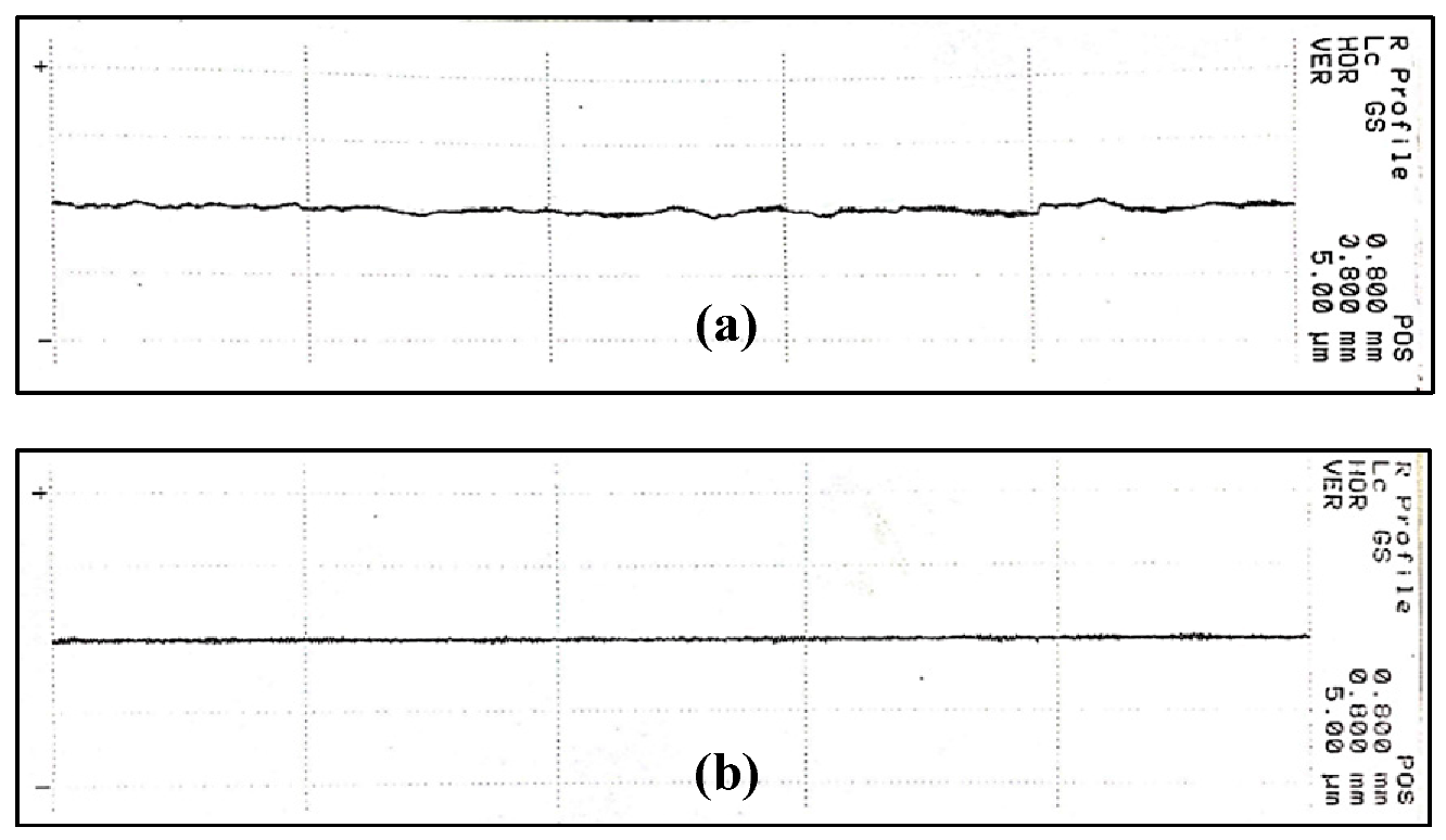
The prepared tribo pins are proceeded with surface grinding process by Impressive Edge Sdn. Bhd. before initiating the friction and wear tests. Next, the surface roughness measurements are carried out with the ground surface tribo pins and counter-ring via Mahr S2 surface profilometer to ensure standardized surface roughness and condition upon tests completion as an assurance on the accuracy of the obtained results. Figure 10 shows the surface profile of tribo pins and counter-ring, respectively, before the friction and wear tests.
The friction and wear tests with normal loads variation and sliding distance are carried out. Varying normal loads (19.62 N, 39.24 N, 58.86 N, 78.48 N, 98.10 N, and 117.72 N) are applied in normal loads variation friction and wear tests with constant sliding speed of 650 rpm for 1200 s. For sliding distance friction and wear tests, it is carried out with constant normal load of 93.195 N and constant sliding speed of 725 rpm for 5400 s. Both friction and wear tests are conducted on all the prepared specimens such as the as-received AA5083 specimen, the FSPed AA5083/g-SiC specimens (0 vol%, 5 vol%, 10 vol% and 15 vol%), and the FSPed AA5083/SiC specimen (15 vol%), respectively. Note that both mentioned tests are carried out by utilizing 0.2 mL Petronas Mach 5 engine oil to simulate starve lubrication condition [22]. To compute the coefficient of friction between pin and ring contact pair, Equations (3) and (4) are implied.
F t = m V + 0.172 0.156  
μ = F t F N
where Ft is the tangible force experienced by the strain gauge, and mV is the millivolt reading generated from the strain gauge. The tangible force, Ft is applied to compute the friction coefficient, µ, by dividing Ft by the exerted normal load, FN, applied onto the pin and ring contact pair. The electronic balance (SHIMADZU, Kyoto, Japan) Model: AW-220 is used to measure the weight loss of each specimen in a high-precision manner (0.1 mg) after each friction and wear test by comparing their initial and final weights.

3. Results and Discussions

3.1. Microstructural Analysis

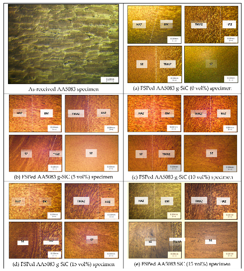
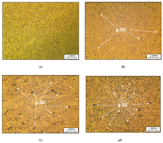
Figure 11 shows the microstructures of the prepared specimens consisting of as-received AA5083 specimen, FSPed AA5083/g-SiC specimens, and FSPed AA5083/SiC specimen. By observing Figure 11 in detail, the specimens undergo FSP have different FSP zones, which can be distributed into base metal (BM), heat-affected zone (HAZ), thermal-mechanically affected zone (TMAZ), and stir zone (SZ). Such observations are like the FSP outcomes obtained in [23]. Figure 12 shows the outcomes of FSPed AA5083 g-SiC specimens with different volume fractions (0 vol% to 15 vol%) within SZ after FSP via the usage of metallurgical scope (20× magnification).
Based on Figure 11, the grain refinement is observed for all the FSPed AA5083 specimens regardless of their variations, which can be justified due to local thermal hysteresis experienced during FSP. Different dynamic recrystallization (DRX) is experienced for different FSP zones due to the intensity of encountered temperature gradient during FSP, as mentioned in [23]. Moreover, the effect of reinforcements for grain refinement is also analyzed by using imageJ for grain size measurement. FSPed AA5083/SiC specimen has the finest grain size followed by 15 vol%, 10 vol%, 5 vol %, 0 vol% FSPed AA5083/g-SiC specimens, and as-received AA5083 specimen. The domination of SiC contributes to additional local deformation in breaking up grains compared to GNP [24], which is also crucial in determining the overall microhardness of specimens, as related to the Hall-Petch relation [25].

3.2. Microhardness Tests Results

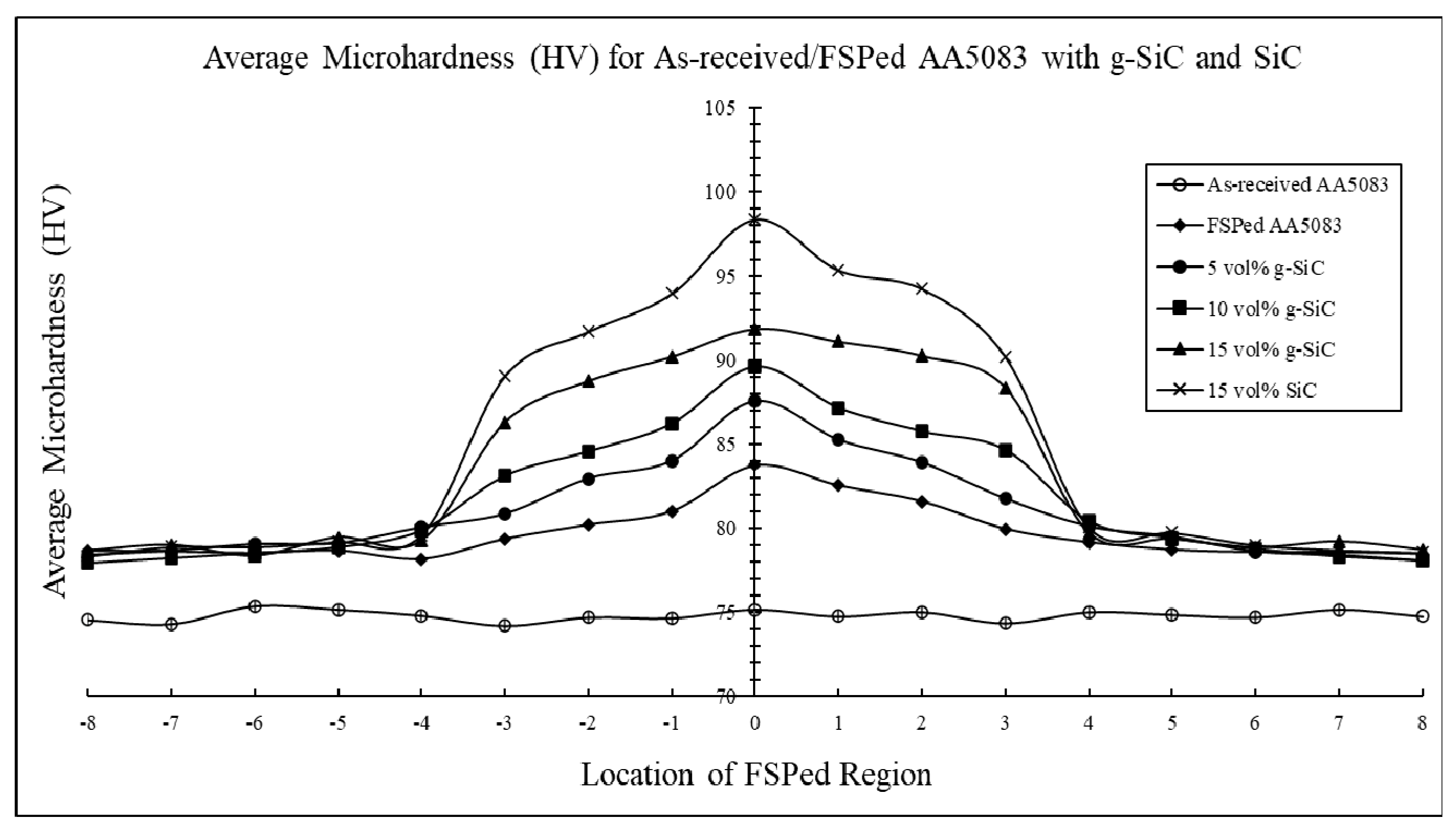
By referring to Figure 13, the improvement of average hardness for all the FSPed specimens is significant compared with as-received AA5083, especially at the stir zone (SZ). FSPed AA5083 (0 vol% g-SiC) has an improvement of 11.44% in microhardness compared to as-received AA5083. FSPed AA5083/g-SiC specimens achieve a continuous microhardness improvement, which has an increasing trend upon the addition of volume fraction. The 5 vol% g-SiC specimen improves 16.5%, the 10 vol% g-SiC specimen improves 19.23%, while the 15 vol% g-SiC specimen improves the most, by 22.22%, as compared to the as-received AA5083. However, the FSPed AA5083 (15 vol% SiC) specimen has the most significant improvement of 30.87% in microhardness compared to as-received AA5083.
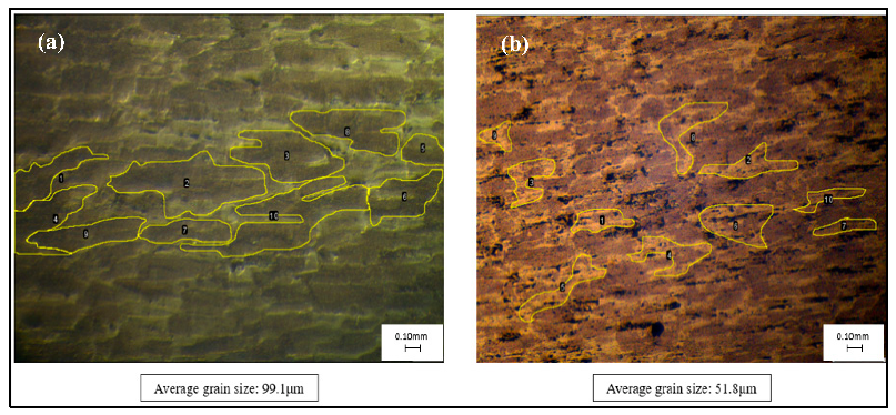
The increment trend of microhardness across BM to SZ is similar to Yuvaraj et al. [26] whereby the maximum hardness is discovered within SZ since BM, HAZ, and TMAZ are not entirely impacted by the grain refinement and grain boundary pinning effect during Friction Stir Processing (FSP), leading to lower microhardness. Besides, the clarification on the higher microhardness on base metal (BM) region is carried out using imageJ, an image processing software to measure the grain size between FSPed AA5083 specimens and as-received AA5083 specimen, as shown in Figure 14. As a result, FSPed AA5083 specimens have slightly finer grain than as-received AA5083 at BM region, resulting in higher microhardness, which is similar to the research work done by Azizieh et al. [25].

3.3. Friction and Wear Tests Results

3.3.1. Effect of Normal Loads on Coefficient of Friction and Wear Rate

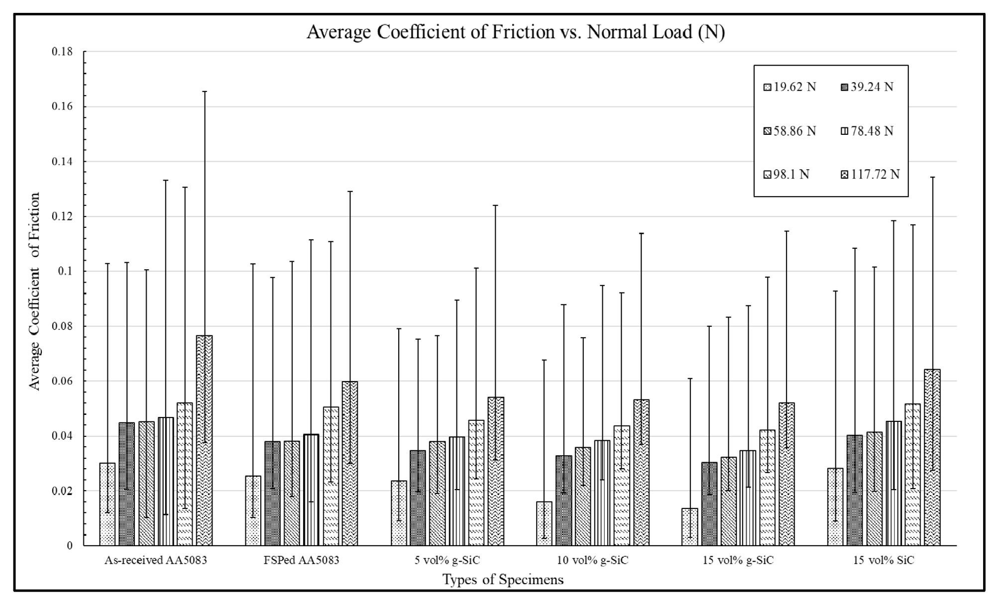
By referring to Figure 15, the reduction of average COF is achieved by Friction Stir Processed (FSPed) specimens compared to as-received AA5083. FSPed AA5083 (0 vol% g-SiC) reduces 14.59% in COF, while a slightly lower reduction of average COF is achieved by FSPed AA5083 (15 vol% SiC) specimen with a percentage of 8.34% when both specimens are compared with as-received AA5083. Significant COF reduction is achieved by FSPed AA5083/g-SiC specimens, which has an increasing trend of reduction as the volume fraction of g-SiC increases. The 5 vol% g-SiC specimen reduces 20.22%, the 10 vol% g-SiC specimen reduces 25.58%, while the 15 vol% g-SiC specimen reduces 30.68% in terms of average COF, compared to as-received AA5083.
The obtained average COF for all the specimens follows the trend whereby the higher the exerted normal load, the larger the encountered COF. This is due to the stability of tribo film formation since the formed tribo film will not be destroyed faster in smaller applied normal load than higher applied normal load [27]. The overall COF experienced by FSPed AA5083/SiC reinforced specimen tends to be higher than FSPed AA5083/g-SiC specimens regardless of the volume fraction when the exerted normal load increases due to the increasing penetration rate of SiC particles into the unreinforced counter surface, contributing to higher frictional force required to overcome during the sliding of the specimen over the counter-ring [28]. The COF reduction becomes significant when g-SiC volume fraction increases from 5 vol% to 15 vol%. Such scenario is due to the advantage of utilizing GNP, whereby GNP is treated as the protective layer between the counter-ring and the specimen’s surface by acting as the lubricating layer to enhance both abrasive and adhesive wear resistance [19].
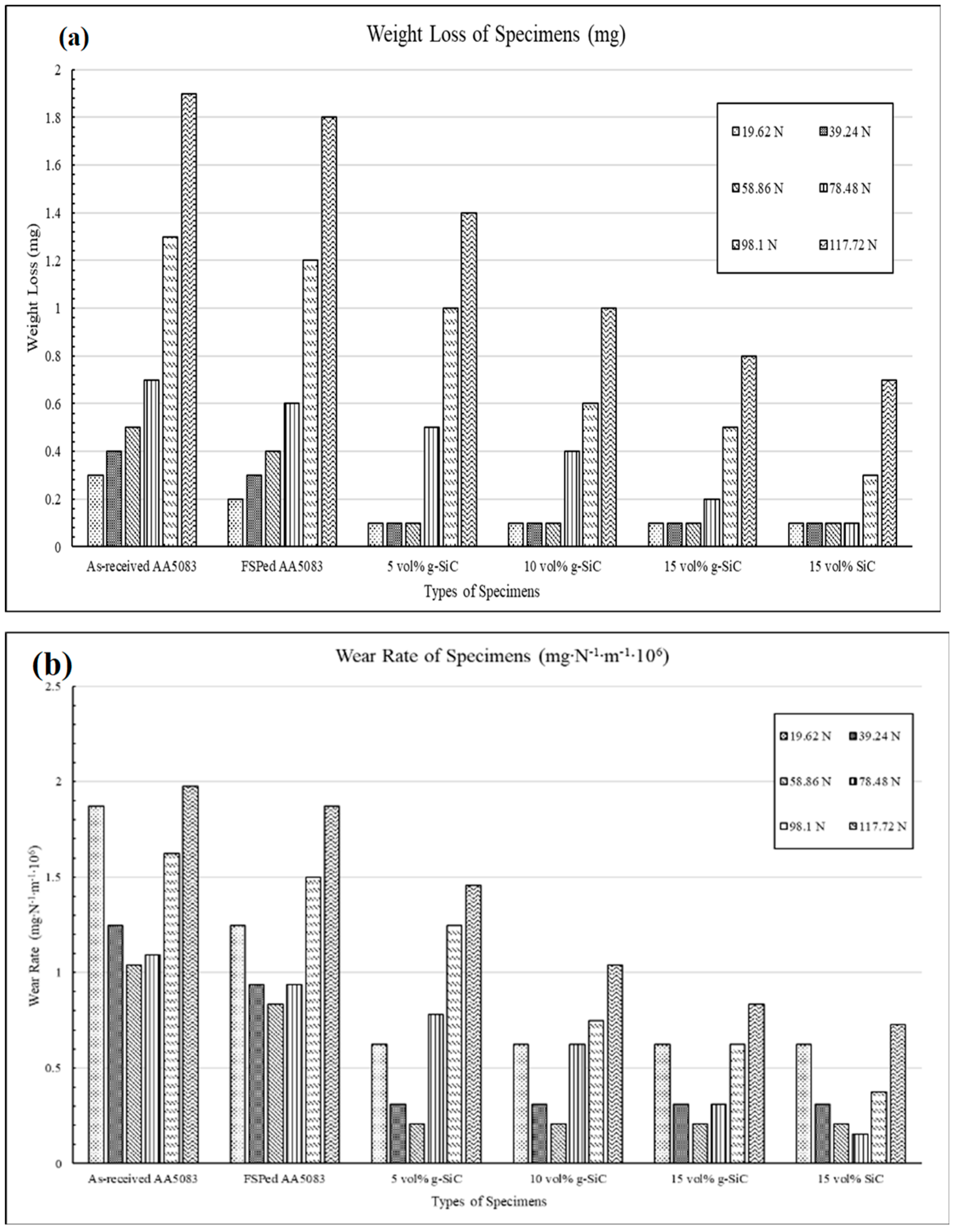
Apart from the discussed COF and surface contact temperature, the weight loss and wear rate for all prepared specimens subjected to friction and wear tests under normal load variations is also captured for each test cycle, as shown in Figure 16.
By referring to Figure 16a, the total weight loss achieved by as-received AA5083 is the highest, and a reduction of total weight loss can be observed on Friction Stir Processed (FSPed) specimens. FSPed AA5083 (0 vol% g-SiC) achieves a total weight loss reduction of 11.76 % compared to as-received AA5083, while more reduction of total weight loss is observed within FSPed AA5083/g-SiC (5 vol%, 10 vol%, 15 vol%) specimens and FSPed AA5083 (15vol% SiC) specimen. 5 vol% g-SiC specimen reduces the total weight loss by 37.25%, 10 vol% g-SiC specimen reduces the total weight loss by 54.90%, and 15 vol% g-SiC specimen reduces the total weight loss by 64.71%, compared to as-received AA5083. However, the FSPed AA5083 (15 vol% SiC) specimen achieves the most significant reduction, whereby 72.55% of weight loss is reduced compared to as-received AA5083.
By referring to Figure 16b, the obtained wear rate result follows the trend of the weight loss result whereby the as-received AA5083 specimen experiences the highest wear rate among all the prepared specimens while the FSPed AA5083/SiC specimen experiences the least wear rate. Such a similar trend is due to the relationship between the wear rate and weight loss [29]. The total wear rate reduction compared to as-received AA5083 is arranged in ascending order starting from FSPed AA5083 (0 vol% g-SiC) (17.27%), followed by 5 vol% g-SiC (47.71%), 10 vol% g-SiC (59.81%), 15 vol% g-SiC (67.10%), and FSPed AA5083 (15 vol% SiC) (72.86%).
The least weight loss and wear rate experienced by FSPed AA5083/SiC specimen can be justified based on its highest microhardness result compared to other specimens, which is related to Hall-Petch relation, contributing to better wear resistance. However, the obtained wear rate tends to be decreasing from 19.62 N to 58.86 N for all the specimens and increase from 78.48 N to 117.72 N. Such scenario is due to the slightly significant wear experienced by each of the varied specimens under large exerted normal load although the overall wear rate is following the trend of weight loss whereby the least wear rate is experienced by FSPed AA5083/SiC specimen.

3.3.2. Effect of Sliding Distance on Coefficient of Friction and Wear Rate

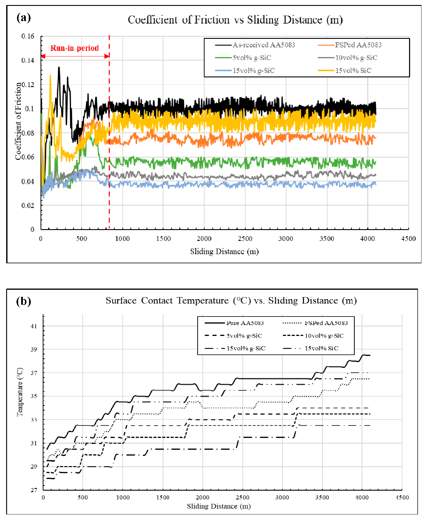
Based on Figure 17a, the reduction of average COF is achieved by Friction Stir Processed (FSPed) specimens compared to as-received AA5083. FSPed AA5083 (0 vol% g-SiC) reduces 26.66% in COF, while a slightly lower reduction of average COF is achieved by FSPed AA5083 (15 vol% SiC) specimen with a percentage of 12.05% when both specimens are compared with as-received AA5083. Significant COF reduction is achieved by FSPed AA5083/g-SiC specimens, which has an increasing trend of reduction as the volume fraction of g-SiC increases. The 5 vol% g-SiC specimen reduces 43.68%, the 10 vol% g-SiC specimen reduces 55.04%, while the 15 vol% g-SiC specimen reduces 61.13% in terms of average COF, compared to as-received AA5083.
The overall coefficient of friction trend for as-received AA5083 is deemed to be the highest compared to the rest of the FSPed AA5083 g-SiC- and SiC-reinforced specimen due to the direct wearing onto the specimen’s surface since there is no involvement of any reinforcement within the specimen, contributing to larger grain size and lower hardness than the other specimens, as supported by Bharti et al. [30]. Higher COF trend experienced by FSPed AA5083/SiC-reinforced specimen is mainly due to the protrusion of SiC particles from the surface, acting as a third body abrasive wear towards the unreinforced counter-ring, contributing to higher frictional force during sliding, as justified by Akbarpour et al. [31].
Significant COF reduction and stabilization is achieved by FSPed AA5083/g-SiC-reinforced specimens, especially when the volume fraction of g-SiC increases. The formation of tribo film between two contacting surfaces with weak Van der Waals bonding structure of GNP provides self-lubricating features in nature, contributing to the mentioned COF reduction [29]. The outstanding thermal conductivity of GNP also enhances frictional heat dissipation, leading to stabilization of COF fluctuations, as shown in Figure 17b.
Apart from the discussed COF and surface contact temperature, the weight loss and wear rate for all prepared specimens subjected to the mentioned sliding distance is captured for each test cycle, as shown in Figure 18.
By referring to Figure 18a, the total weight loss achieved by as-received AA5083 is the highest, and a reduction of total weight loss can be observed on FSPed specimens. FSPed AA5083 (0 vol% g-SiC) achieves a total weight loss reduction of 35.14% compared to as-received AA5083, while more reduction of total weight loss is observed within FSPed AA5083/g-SiC specimens and FSPed AA5083/SiC specimen. The 5 vol% g-SiC specimen reduces the total weight loss by 51.35%, the 10 vol% g-SiC specimen reduces the total weight loss by 67.57%, and the 15 vol% g-SiC specimen reduces the total weight loss by 72.97%, as compared to as-received AA5083. However, the FSPed AA5083 (15 vol% SiC) specimen achieved the most significant reduction, whereby 78.38% of weight loss is reduced compared to as-received AA5083. A similar trend is observed for wear rate of specimens since wear rate is related to the experienced weight loss [29], as shown in Figure 18b. The most weigh loss is experienced by as-received AA5083 while the FSPed AA5083/SiC specimen experienced the least due to the wear resistance equipped within the specimens, as mentioned in Shafiei et al. [32]. The strength of SiC in grain refining compared to GNP can be the alternative clarification since it contributes to better microhardness of specimens, leading to lesser weight loss and wear rate, as proven by Hall-Petch relation [25].

3.4. Wear Surface Morphology of Specimens

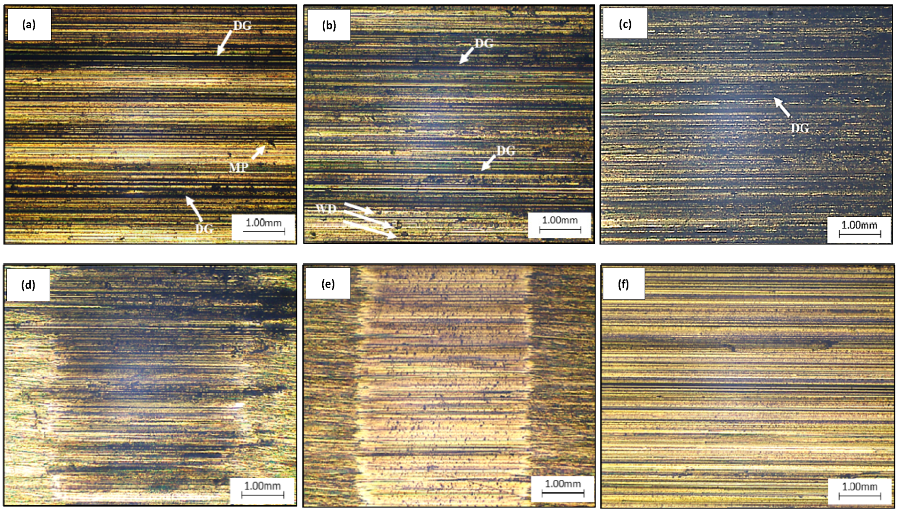
By referring to Figure 19, micro-pit and wear debris exist within the as-received AA5083 and FSPed AA5083 (0 vol% g-SiC) after the sliding distance friction and wear test. The existence of micro-pit within as-received AA5083 specimen and the wear debris sticking on the FSPed AA5083 (0 vol% g-SiC) specimen indicate that abrasive and adhesive wear are experienced by respective specimen, as defined in [33]. Fretting wear are deemed to be discovered within the FSPed AA5083/g-SiC specimens and FSPed AA5083/SiC specimen since minor surface defects are discovered due to low amplitude of sliding [33].
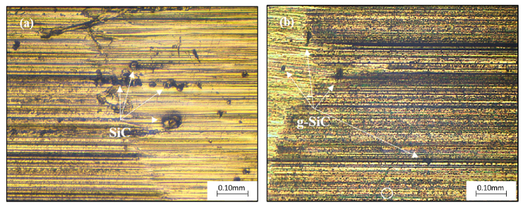
Besides, the severity of deep grooves and scratches are also more significant in the as-received AA5083 than the rest of the specimens due to lower microhardness, leading to more serious wear and material loss than those FSPed and reinforced specimens. The severity of surface wearing tends to decrease as validated from the number of deep grooves and severe scratches portrayed in Figure 19 due to the higher microhardness of the specimens upon achieving more refined grain size, as proven in Chak et al. [34] and Tang et al. [35]. The protrusion of SiC particles is also discovered within the surfaces of both FSPed AA5083/SiC and FSPed AA5083/g-SiC-reinforced specimens, as shown in Figure 20. However, it is noticeable that the protruded SiC is covered with a black layer for FSPed AA5083/g-SiC specimen, which is suspectable to be the reinforced GNP. It thus clarifies the higher COF experienced by FSPed AA5083/SiC specimen than FSPed AA5083/g-SiC specimens during the friction and wear tests.
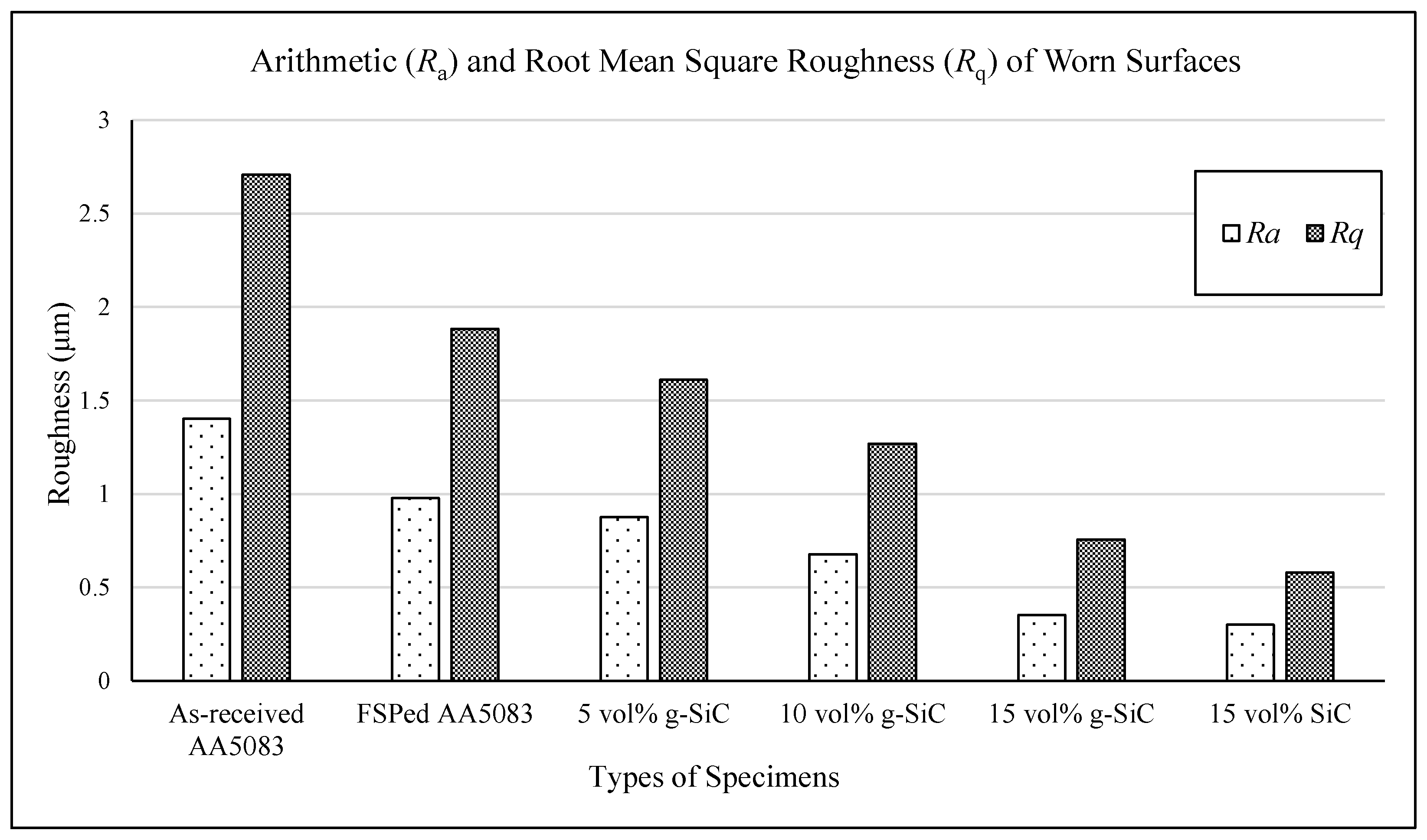
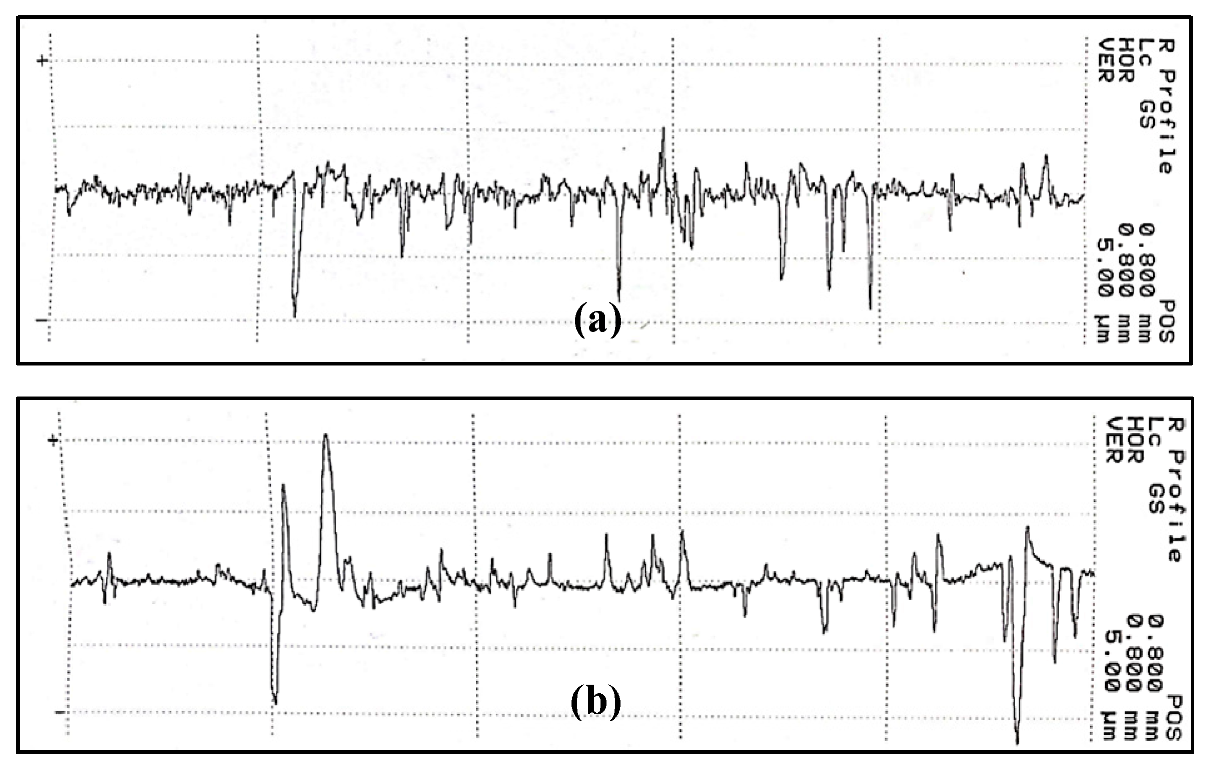
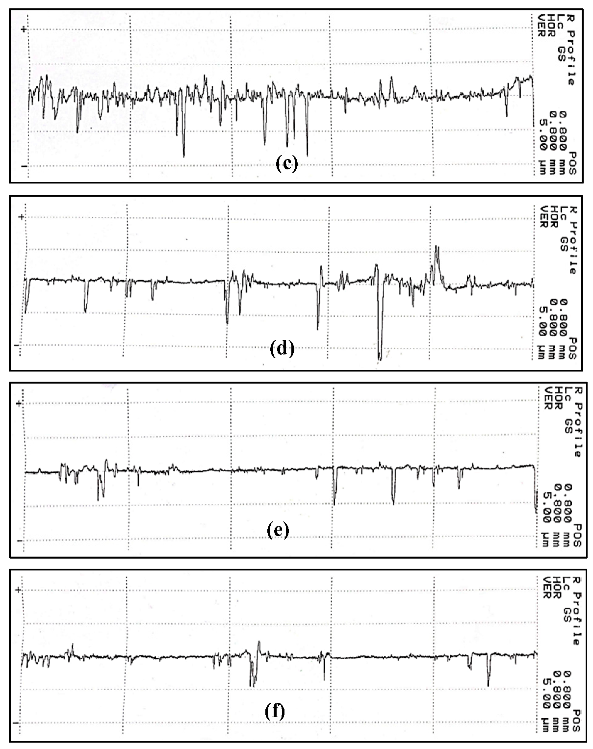
As for further analysis on the severity of wear experienced by each specimen, surface roughness measurement is carried out to determine the surface condition of each specimen after the friction and wear tests. Ra (Roughness Average), Rq (RMS Roughness), and Rsk (Skewness) are the focus of the analysis, as tabulated in Table 2 and Figure 21. Figure 22 displays the overview of the surface roughness outcomes for each specimen.
Based on Figure 21, the obtained surface roughness (Ra and Rq) ought to reduce from FSPed AA5083 (0 vol% g-SiC) to FSPed AA5083 (15 vol% SiC) specimen compared to as-received AA5083, indicating that the decrement of wear severity since surface roughness is related to the experienced wear rate, as proven in [36]. It thus verifies the wearing impacts observed and described according to Figure 19 is valid whereby the most serious wear is experienced by as-received AA5083, while trivial wear is experienced by 15 vol% SiC specimen.

4. Conclusions

In this study, the procured AA5083-H112 undergoes FSP successfully for the fabrication of FSPed AA5083/g-SiC specimens (0 vol%–15 vol%) and FSPed AA5083/SiC specimen (15 vol%). The tribological performance, microstructure, microhardness, and wear surface morphology of prepared specimens were observed and analyzed. The obtained results are depicted as follows:
  • FSP was successful in fabricating the required specimens and the FSP zones can be easily differentiated (BM, HAZ, TMAZ, and SZ). As an overview, the average grain size of specimens decreased after FSP, especially FSPed AA5083/g-SiC and FSPed AA5083/SiC specimens.
  • The microhardness of FSPed AA5083/g-SiC and FSPed AA5083/SiC specimens increased compared to as-received AA5083. The highest microhardness (98.35 Hv) is achieved by FSPed AA5083/SiC (15 vol%) due to the domination of SiC in grain refinement compared to GNP.
  • Significant average COF reduction was achieved by both FSPed AA5083/g-SiC compared to as-received AA5083, as observed in conducted friction and wear tests.
  • The average COF experienced by the FSPed AA5083/SiC specimen is higher than the FSPed AA5083/g-SiC specimens (0 vol%–15 vol%) due to the protrusion of SiC particles from the surface, as observed under the captured micrograph.
  • The optimum average COF and weight loss reduction with minimum surface contact temperature were discovered within FSPed AA5083/g-SiC (15 vol%) specimen where 61.13% and 72.97% of reduction are achieved, respectively. Such outstanding performance is due to the formation of tribo film by GNP between two contacting surfaces.
  • Severity of surface defects decreased for both FSPed AA5083/g-SiC and FSPed AA5083/SiC specimens due to FSP and involvements of hybrid reinforcements, enhancing the overall wear resistance of the prepared specimens.
  • The effectiveness of GNP in enhancing the tribological performance of specimens by acting as the solid lubrication between two sliding surfaces is as outstanding as the effectiveness of SiC in grain refining and enhancing microhardness of the specimens by acting as load transferring element [37,38].
  • FSP process parameters can be optimized [39], while a wider range of g-SiC volume fractions [40] with alteration of base metal [41] can be prepared for further studies to understand the effect of such factors in improvising the mechanical properties and tribological performance of surface-reinforced metal composite.

Author Contributions

Conceptualization, K.W.L. and J.L.T.; Methodology, K.W.L. and J.L.T.; Formal analysis, K.W.L. and J.L.T.; Investigation, K.W.L. and J.L.T.; Resources, K.W.L.; Data curation, J.L.T.; Writing—original draft preparation, K.W.L. and J.L.T.; Writing—review and editing, K.W.L. and J.L.T.; Supervision, K.W.L.; Project administration, K.W.L. All authors have read and agreed to the published version of the manuscript.

Funding

This research received no external funding.

Data Availability Statement

Available upon request.

Acknowledgments

Special thanks to Faculty of Engineering and Technology, Multimedia University for partial financial support and empowering in the accomplishment of this study.

Conflicts of Interest

The authors declare no conflict of interest.

References

  1. Hutchings, I.; Shipway, P. Tribology: Friction and Wear of Engineering Materials; Butterworth-Heinemann: Oxford, UK, 2017. [Google Scholar]
  2. Ritesh, P.; Shanmugasundaram, A. An investigation of molybdenum surface reinforcement on the hardness and wear properties of AISI 630. Trans. IMF 2018, 96, 95–102. [Google Scholar] [CrossRef]
  3. Mahmoud, E.R.; Ikeuchi, K.; Takahashi, M. Fabrication of SiC particle reinforced composite on aluminium surface by friction stir processing. Sci. Technol. Weld. Join. 2008, 13, 607–618. [Google Scholar] [CrossRef]
  4. Rathee, S.; Maheshwari, S.; Siddiquee, A.N.; Srivastava, M. A review of recent progress in solid state fabrication of composites and functionally graded systems via friction stir processing. Crit. Rev. Solid State Mater. Sci. 2018, 43, 334–366. [Google Scholar] [CrossRef]
  5. Hu, P.; Cao, L.; Su, J.; Li, Q.; Li, Y. Distribution characteristics of salt-out particles in steam turbine stage. Energy 2020, 192, 116626. [Google Scholar] [CrossRef]
  6. Pawar, S.R.; Phalle, V.M. Influence of Wear on the Dynamic Performance Characteristics of Non-Recessed Hole Entry Hydrostatic Conical Journal Bearing. International Conference on Advances in Thermal Systems, Materials and Design Engineering (ATSMDE2017). 2017, pp. 1–4. Available online: https://www.researchgate.net/profile/Sanjay-Pawar-19/publication/362518286_SSRN-id3101411_1/links/62ee0cac0b37cc344774b783/SSRN-id3101411-1.pdf (accessed on 28 January 2023). [CrossRef]
  7. Teo, G.S.; Liew, K.W.; Kok, C.K. Enhancement of Microhardness and Tribological Properties of Recycled AA 6063 Using Energy-Efficient and Environment-Friendly Friction Stir Processing. IOP Conf. Ser. Earth Environ. Sci. 2021, 943, 012019. [Google Scholar] [CrossRef]
  8. Gupta, M.K. Friction stir process: A green fabrication technique for surface composites—A review paper. SN Appl. Sci. 2020, 2, 532. [Google Scholar] [CrossRef] [Green Version]
  9. Ratnayake, S.P. Characterization studies of ceramic-based composites related to functionalized filler-matrix interface. In Interfaces in Particle and Fibre Reinforced Composites; Woodhead Publishing: Sawston, UK, 2020; pp. 369–389. [Google Scholar]
  10. Kaushik, N.C.; Rao, R.N. Effect of grit size on two body abrasive wear of Al 6082 hybrid composites produced by stir casting method. Tribol. Int. 2016, 102, 52–60. [Google Scholar] [CrossRef]
  11. Moghadam, A.D.; Omrani, E.; Menezes, P.L.; Rohatgi, P.K. Mechanical and tribological properties of self-lubricating metal matrix nanocomposites reinforced by carbon nanotubes (CNTs) and graphene—A review. Compos. Part B Eng. 2015, 77, 402–420. [Google Scholar] [CrossRef]
  12. Rashad, M.; Pan, F.; Asif, M. Magnesium matrix composites reinforced with graphene nanoplatelets. Graphene Mater. Fundam. Emerg. Appl. 2015, 20, 151–189. [Google Scholar]
  13. Zhao, Z.; Feng, C.; Wang, Y.; Yang, J. Bending and vibration analysis of functionally graded trapezoidal nanocomposite plates reinforced with graphene nanoplatelets (GPLs). Compos. Struct. 2017, 180, 799–808. [Google Scholar] [CrossRef]
  14. Bisht, A.; Srivastava, M.; Kumar, R.M.; Lahiri, I.; Lahiri, D. Strengthening mechanism in graphene nanoplatelets reinforced aluminum composite fabricated through spark plasma sintering. Mater. Sci. Eng. A 2017, 695, 20–28. [Google Scholar] [CrossRef]
  15. Kaushik, N.C.; Rao, R.N. The effect of wear parameters and heat treatment on two body abrasive wear of Al–SiC–Gr hybrid composites. Tribol. Int. 2016, 96, 184–190. [Google Scholar] [CrossRef]
  16. Boadu, K.O.; Joel, O.F.; Essumang, D.K.; Evbuomwan, B.O. A review of methods for removal of contaminants in used lubricating oil. Chem. Sci. Int. J. 2019, 26, 1–11. [Google Scholar] [CrossRef]
  17. Kumar, G.V.; Rao, C.S.; Selvaraj, N.; Bhagyashekar, M.S. Studies on Al6061-SiC and Al7075-Al2O3 metal matrix composites. J. Min. Mater. Charact. Eng. 2010, 9, 43–55. [Google Scholar]
  18. Butola, R.; Ranganath, M.S.; Murtaza, Q. Fabrication and optimization of AA7075 matrix surface composites using Taguchi technique via friction stir processing (FSP). Eng. Res. Express 2019, 1, 025015. [Google Scholar] [CrossRef]
  19. Sharma, A.; Narsimhachary, D.; Sharma, V.M.; Sahoo, B.; Paul, J. Surface modification of Al6061-SiC surface composite through impregnation of graphene, graphite & carbon nanotubes via FSP: A tribological study. Surf. Coat. Technol. 2019, 368, 175–191. [Google Scholar]
  20. Department of Materials Science & Metallurgy-University of Cambridge. Available online: www.doitpoms.ac.uk (accessed on 18 June 2022).
  21. Patel, V.; Li, W.; Vairis, A.; Badheka, V. Recent development in friction stir processing as a solid-state grain refinement technique: Microstructural evolution and property enhancement. Crit. Rev. Solid State Mater. Sci. 2019, 44, 378–426. [Google Scholar] [CrossRef]
  22. Boyce, M.P. Gas Turbine Engineering Handbook; Elsevier: Oxford, UK, 2011. [Google Scholar]
  23. Su, J.Q.; Nelson, T.W.; Sterling, C.J. Friction stir processing of large-area bulk UFG aluminum alloys. Scr. Mater. 2005, 52, 135–140. [Google Scholar] [CrossRef]
  24. Ahmad, I.; Islam, M.; Subhani, T.; Zhu, Y. Toughness enhancement in graphene nanoplatelet/SiC reinforced Al2O3 ceramic hybrid nanocomposites. Nanotechnology 2016, 27, 425704. [Google Scholar] [CrossRef] [PubMed]
  25. Azizieh, M.; Kokabi, A.H.; Abachi, P. Effect of rotational speed and probe profile on microstructure and hardness of AZ31/Al2O3 nanocomposites fabricated by friction stir processing. Mater. Des. 2011, 32, 2034–2041. [Google Scholar] [CrossRef]
  26. Yuvaraj, N.; Aravindan, S. Fabrication of Al5083/B4C surface composite by friction stir processing and its tribological characterization. J. Mater. Res. Technol. 2015, 4, 398–410. [Google Scholar] [CrossRef] [Green Version]
  27. Akbari, M.; Shojaeefard, M.H.; Asadi, P.; Khalkhali, A. Wear performance of A356 matrix composites reinforced with different types of reinforcing particles. J. Mater. Eng. Perform. 2017, 26, 4297–4310. [Google Scholar] [CrossRef]
  28. Sert, A.B.; Celik, O.N. Wear Behavior of SiC-Reinforced Surface Composite A17075-T651 Aluminum Alloy Produced Using Friction Stir Processing; NISCAIR-CSIR: New Delhi, India, 2014; pp. 1–9. [Google Scholar]
  29. AbuShanab, W.S.; Moustafa, E.B. Effects of friction stir processing parameters on the wear resistance and mechanical properties of fabricated metal matrix nanocomposites (MMNCs) surface. J. Mater. Res. Technol. 2020, 9, 7460–7471. [Google Scholar] [CrossRef]
  30. Bharti, S.; Ghetiya, N.D.; Patel, K.M. Micro-hardness and wear behavior of AA2014/Al2O3 surface composite produced by friction stir processing. SN Appl. Sci. 2020, 2, 1–6. [Google Scholar] [CrossRef]
  31. Akbarpour, M.R.; Najafi, M.; Alipour, S.; Kim, H.S. Hardness, wear and friction characteristics of nanostructured Cu-SiC nanocomposites fabricated by powder metallurgy route. Mater. Today Commun. 2019, 18, 25–31. [Google Scholar] [CrossRef]
  32. Shafiei-Zarghani, A.; Kashani-Bozorg, S.F.; Zarei-Hanzaki, A. Microstructures and mechanical properties of Al/Al2O3 surface nano-composite layer produced by friction stir processing. Mater. Sci. Eng. A 2009, 500, 84–91. [Google Scholar] [CrossRef]
  33. Stachowiak, G.W.; Batchelor, A.W. Engineering Tribology; Butterworth-Heinemann: Oxford, UK, 2013. [Google Scholar]
  34. Chak, V.; Chattopadhyay, H. Synthesis of graphene–aluminium matrix nanocomposites: Mechanical and tribological properties. Mater. Sci. Technol. 2021, 37, 467–477. [Google Scholar] [CrossRef]
  35. Tang, J.; Shen, Y.; Li, J. Influences of friction stir processing parameters on microstructure and mechanical properties of SiC/Al composites fabricated by multi-pin tool. J. Manuf. Process. 2019, 38, 279–289. [Google Scholar] [CrossRef]
  36. Kubiak, K.J.; Liskiewicz, T.W.; Mathia, T.G. Surface morphology in engineering applications: Influence of roughness on sliding and wear in dry fretting. Tribol. Int. 2011, 44, 1427–1432. [Google Scholar] [CrossRef] [Green Version]
  37. Devaraju, A.; Kumar, A.; Kotiveerachari, B. Influence of addition of Grp/Al2O3p with SiCp on wear properties of aluminum alloy 6061-T6 hybrid composites via friction stir processing. Trans. Nonferrous Met. Soc. China 2013, 23, 1275–1280. [Google Scholar] [CrossRef]
  38. Guo, X.; Wang, R.; Zheng, P.; Lu, Z.; Yang, H. Pressureless sintering of multilayer graphene reinforced silicon carbide ceramics for mechanical seals. Adv. Appl. Ceram. 2019, 118, 409–417. [Google Scholar] [CrossRef]
  39. Teo, G.S.; Liew, K.W.; Kok, C.K. Optimization of Friction Stir Processing Parameters of Recycled AA 6063 for Enhanced Surface Microhardness and Tribological Properties. Metals 2022, 12, 310. [Google Scholar] [CrossRef]
  40. El-Mahallawy, N.A.; Zoalfakar, S.H.; Maboud, A.A. Microstructure and mechanical properties of Al/SiC surface composite with different volume fractions using friction stir process. IOP Conf. Ser. Mater. Sci. Eng. 2019, 634, 1–8. [Google Scholar] [CrossRef] [Green Version]
  41. Nascimento, F.; Santos, T.; Vilaça, P.; Miranda, R.M.; Quintino, L. Microstructural modification and ductility enhancement of surfaces modified by FSP in aluminium alloys. Mater. Sci. Eng. A 2009, 506, 16–22. [Google Scholar] [CrossRef]
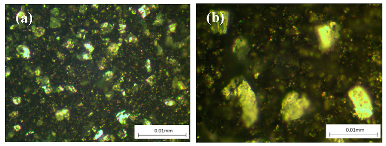
Figure 1. Micrograph of homogenously mixed g-SiC under (a) 20× magnification and (b) 50× magnification.
Lubricants 11 00124 g001
Figure 2. Process overview for specimens’ preparations.
Lubricants 11 00124 g002
Figure 3. (a) Capping process, (b) FSP for prepared AA5083-H112 samples, (c) FSP outcomes of AA5083-H112 samples.
Lubricants 11 00124 g003
Figure 4. Planned extraction process for microstructural specimens and tribo pins.
Lubricants 11 00124 g004
Figure 5. Engineering drawing for (a) microstructural specimens and (b) tribo pins.
Lubricants 11 00124 g005
Figure 6. Extracted outcomes for (a) microstructural specimens and (b) tribo pins.
Lubricants 11 00124 g006
Figure 7. Surface conditions after (a) grinding, (b) polishing and (c) etching.
Lubricants 11 00124 g007
Figure 8. Schematic diagram for microhardness specimens’ labelling.
Lubricants 11 00124 g008
Figure 9. Schematic diagram of pin-on-ring tribo-tester.
Lubricants 11 00124 g009
Figure 10. Surface roughness profile of (a) tribo pins and (b) counter-ring.
Lubricants 11 00124 g010
Figure 11. Microstructure of prepared specimens under 5× magnification for as-received AA5083 specimen, FSPed AA5083 g-SiC (a) 0 vol%, (b) 5 vol%, (c) 10 vol%, (d) 15 vol% specimens, and (e) FSPed AA5083 SiC (15 vol%) specimen. (BM: base metal, HAZ: heat-affected zone, TMAZ: thermal-mechanically affected zone, SZ: stir zone).
Lubricants 11 00124 g011
Figure 12. 20× magnification microstructure at SZ for FSPed AA5083 (a) 0 vol% g-SiC, (b) 5 vol% g-SiC, (c) 10 vol% g-SiC, (d) 15 vol% g-SiC.
Lubricants 11 00124 g012
Figure 13. Average microhardness for as-received AA5083, FSPed AA5083, and FSPed AA5083 with g-SiC (5, 10, 15%) and SiC (15%) specimens. Confidence Interval (CI) of each average microhardness values are about ±0.49.
Lubricants 11 00124 g013
Figure 14. Average grain size for (a) as-received AA5083, average grain size = 99.1 µm and (b) BM of FSPed AA5083 (0 vol% g-SiC), average grain size = 51.8 µm.
Lubricants 11 00124 g014
Figure 15. Overall trend of coefficient of friction (COF) against normal load with the constant sliding speed of 650 rpm and sliding duration of 1200 s for 5 vol% g-SiC, 10 vol% g-SiC, 15 vol% g-SiC, and 15 vol% SiC specimen compared to as-received AA5083 and FSPed AA5083 (0 vol% g-SiC).
Lubricants 11 00124 g015
Figure 16. (a) Weight loss, (b) Wear rate of specimens subjected to the constant sliding speed of 650 rpm for 1200 s sliding duration.
Lubricants 11 00124 g016
Figure 17. Overall trend of (a) coefficient of friction, and (b) surface contact temperature against sliding distance (4000 m) with the constant normal load of 93.195 N and sliding speed of 725 rpm for 5 vol% g-SiC specimen, 10 vol% g-SiC specimen, 15 vol% g-SiC specimen, and 15 vol% SiC specimen compared to as-received AA5083 and FSPed AA5083 (0 vol% g-SiC).
Lubricants 11 00124 g017
Figure 18. (a) Weight loss, (b) Wear rate of specimens subjected to 4000 m sliding distance under the constant sliding speed of 725 rpm and normal load 93.195 N.
Lubricants 11 00124 g018
Figure 19. Worn surface of specimens (a) as-received AA5083; (b) FSPed AA5083 (0 vol% g-SiC); (c) FSPed 5 vol% g-SiC specimen; (d) FSPed 10 vol% g-SiC specimen; (e) FSPed 15 vol% g-SiC specimen; (f) FSPed 15 vol% SiC specimen after undergoing sliding distance of 4000 m with consistent 93.195 N normal load exertion and 725 rpm sliding speed. (DG: deep groove; MP: micro-pit; WD: wear debris).
Lubricants 11 00124 g019
Figure 20. Protruded SiC particles from (a) FSPed AA5083/SiC reinforced specimen; (b) FSPed AA5083/g-SiC reinforced specimen.
Lubricants 11 00124 g020
Figure 21. Arithmetic roughness (Ra) and root mean square roughness (Rq) of worn surfaces for each specimen subjected to 4000 m sliding distance under the constant sliding speed of 725 rpm and normal load 93.195 N.
Lubricants 11 00124 g021
Figure 22. Surface roughness profile of worn surfaces for (a) as-received AA5083; (b) FSPed AA5083 (0 vol% g-SiC); (c) FSPed 5 vol% g-SiC specimen; (d) FSPed 10 vol% g-SiC specimen; (e) FSPed 15 vol% g-SiC specimen; (f) FSPed 15 vol% SiC specimen after undergoing sliding distance of 4000 m with consistent 93.195 N normal load exertion and 725 rpm sliding speed.
Lubricants 11 00124 g022aLubricants 11 00124 g022b
Table 1. Chemical composition of AA5083-H112.
ElementSiFeCuMnMgCrZnTiAl
Composition (%)0.210.180.030.604.400.180.020.02Balance
Table 2. Surface roughness of each specimen after friction and wear tests.
Types of SamplesRa (μm)Rq (μm)Rsk
As-received AA50831.4022.708−2.640
FSPed AA5083 (0 vol% g-SiC)0.9781.884−0.380
FSPed AA5083 (5 vol% g-SiC)0.8761.612−1.730
FSPed AA5083 (10 vol% g-SiC)0.6781.268−3.860
FSPed AA5083 (15 vol% g-SiC)0.3530.757−4.530
FSPed AA5083 (15 vol% SiC)0.3000.580−3.640
Disclaimer/Publisher’s Note: The statements, opinions and data contained in all publications are solely those of the individual author(s) and contributor(s) and not of MDPI and/or the editor(s). MDPI and/or the editor(s) disclaim responsibility for any injury to people or property resulting from any ideas, methods, instructions or products referred to in the content.