Article

Study on the Nano-Friction Behavior of Nickel-Based Ag Film Composites Based on Molecular Dynamics

School of Mechanical and Electronical Engineering, Lanzhou University of Technology, Lanzhou 730050, China
*
Author to whom correspondence should be addressed.
Lubricants 2023, 11(3), 110; https://doi.org/10.3390/lubricants11030110
Submission received: 16 January 2023 / Revised: 22 February 2023 / Accepted: 26 February 2023 / Published: 28 February 2023
(This article belongs to the Special Issue Dynamics of Lubricated Interfaces)

Abstract

:
The nano-friction behavior of nickel-based Ag film composites was evaluated using molecular dynamics simulations. The mechanical properties, the surface morphology, the migration behavior of Ag atoms and the defect evolution during repeated friction were investigated. Our results show that the poor mechanical properties of the Ag film surface at the first stage of friction are related to a large amount of abrasive chip pileup. The slip channel with low shear strength formed by secondary friction significantly reduces the friction coefficient of the Ag film surface. Meanwhile, the migration of Ag atoms at the two-phase interface relies mainly on the repeated friction of the grinding ball, and the friction coefficient of the nickel surface decreases as the number of migrating atoms increases. In addition, the extension of defects inside the Ag film and atomic displacement is hindered by the two-phase interface. The defects inside the Ag film near the friction zone gradually evolve from an intrinsic stacking fault to a horizontal stacking fault as the friction proceeds. This is attributed to the horizontal layer-by-layer motion of Ag atoms, promoting the formation of horizontal stacking faults.

1. Introduction

Novel nickel matrix composites with excellent comprehensive performance, such as high-temperature strength, heat fatigue resistance and corrosion resistance, are widely used in the high-tech fields of aerospace, ships and gas-turbine engines [1,2,3]. However, as a matrix material under sliding contact components, the mechanical wear of nickel-based composites is the main cause of their failure under complex operating conditions [4]. Meanwhile, as an excellent solid lubricant, Ag is often used to improve the tribological properties of nickel-based material components [5,6,7]. Thus, an in-depth study of the friction and wear behavior of nickel-based composites containing Ag is of great scientific importance.
Recently, nickel-based composites containing solid lubricants have been widely investigated due to their excellent self-lubricating properties exhibited in a wide temperature range [7,8,9]. These works are required for tribological applications to enhance the lifetime and performance of mechanical systems. Duan et al. [5] investigated the mechanism of Ni/Ag composite glaze film formation. The results showed that a compact glaze film consisting of NiO, Ni and Ag, formed on the contact surface at 600 °C, played an important role in the improvement of the tribological performance. NASA developed a nickel-based composite coating material (containing 10 wt% Ag) that provides low friction over a wide temperature range of 800 °C, which provides solid lubrication for high-speed, high-temperature oil-free turbomachinery [10,11]. Recently, Sun et al. [12,13,14] developed Ag-containing nickel-based composite coating materials that are expected to be widely used in engineering fields such as aerospace, gas turbines and nuclear power. However, the study of material properties based on conventional friction experiments is limited by its length and time scale, and is unable to accurately analyze the microscopic nature at the atomic scale [15]. Meanwhile, the wear behavior is a small and continuous incremental process that allows for material removal at the micro/nanometer level. However, the study of such discrete objects acting on the atomic scale is difficult to achieve through experiments. Therefore, the emergence of molecular dynamics (MD) simulation has undoubtedly built a bridge between macroscopic and microscopic study. This analytical tool enables the analysis of a series of dynamic change processes in solid materials by constructing an ideal model [16,17,18,19]. At the same time, the nature of the simulated object and the environmental conditions can be easily changed according to the actual needs of the research, which is incomparable to the tedious and expensive experimental simulations. Thus, it is necessary to study the dynamic migration, phase transitions and defect structure evolution of materials at the nanoscale by MD from the basic units that constitute the materials.
MD simulations have been used by many researchers to study the nanomachining behavior of materials, and a great deal of constructive work has been performed on chip formation, dislocation evolution and surface thermal effects [20,21,22]. Among them, the study of simulating the nanoscale wear characteristics of nickel matrix composites has been a focus of attention in recent years, aiming to reveal the micro nature of the physical and chemical changes during the friction and wear of nickel matrix composites. Zhu et al. [23] simulated the repetitive nano-friction of nickel-based single-crystal (NBSC) superalloy by the MD method. They found that with the increase in friction cycles, the wear scars of the γ’ phase deepened, whereas those in the γ phase became shallower. Meanwhile, repeated friction reduced the volume and number of stacking faults. Zheng et al. [24] investigated the friction and wear mechanisms of TiC/Ni composites on the nanoscale by the MD method. The results showed that the formation of dislocation entanglement around the TiC phase improved the wear resistance of the workpiece, and the depth of the abrasion became shallow when the grinding ball acted above the TiC phase. Moreover, they further simulated the repeated frictional behavior of nickel-based single crystals in an aqueous environment [25]. It was emphasized that in the presence of water, the force exerted by the grinding ball on the workpiece is shared by the water molecules, which results in a reduction in the machined surface’s roughness, a decrease in the number of internally generated layer errors, a lower overall friction temperature and a nickel substrate protected by water molecules. Fang et al. [26,27] developed a cutting model for multilayer Ni/Cu materials to analyze the mechanism of subsurface damage and material removal during the high-speed grinding of single-crystal Cu and Ni/Cu multilayer films. It was found that smaller grinding speeds led to increased stacking faults and a large volume of material pileups. Recently, Zhou et al. [28] investigated the nano-friction behavior and deformation mechanism of Cu-Ni alloy based on MD simulation. The results showed that the stacking faults and dislocation density increased rapidly with increasing Cu content, and that Cu atoms improved the deformation resistance of the Cu-Ni alloy. Doan et al. [29], on the other hand, conducted an MD simulation study of the NiFeCo alloy grinding process. The results showed that a higher machining speed and a greater grinding depth and tool radius led to a larger grinding force and chipping volume, as well as a higher substrate temperature. In addition, MD simulation studies of the nano-grinding [30,31,32,33,34,35] and nano-polishing [36,37,38,39,40,41] of multiple grains have been widely reported recently. These studies are of great importance in guiding ultra-precision machining and obtaining high-precision surfaces. However, the study of the frictional behavior of Ni/Ag bilayer structures on the nanoscale is rarely reported, and its frictional wear mechanism is still unclear. Hence, it is necessary to systematically investigate the friction and wear behavior of Ni-based Ag film composites at the nanoscale.
To simulate the friction effect of real materials, an MD model of nickel-based Ag film composites with semi-area lubrication is developed for the first time in this paper. The influences of the friction force, friction coefficient, atomic displacement and interface effects on the nanoscale friction and wear behavior of nickel-based Ag film composites were systematically investigated. The migration behavior of Ag atoms on the nickel surface during repeated friction was analyzed, and the lubrication mechanism was revealed. These results provide a good basis for the microscopic study of the lubricating effect of an Ag coating on the substrate.

2. Method

2.1. Simulation Modeling

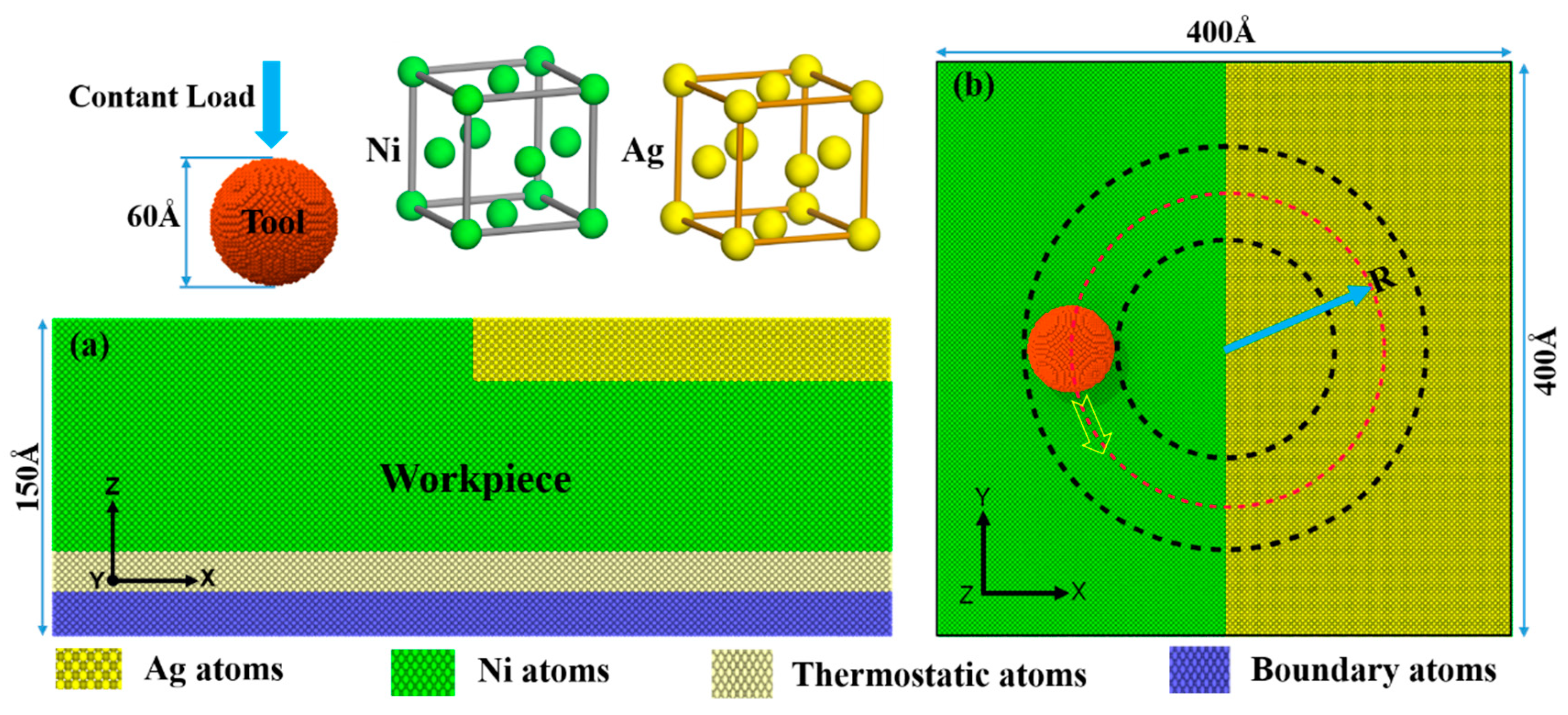
Figure 1 shows the schematic diagram of the real friction experiment of the nickel-based composites. As shown in Figure 1, the Ag particles are dispersed on the substrate surface at the initial stage of friction. When the friction proceeds to a certain stage, more Ag particles are coated on the entire worn surface by frictional heat and extrusion. This has a favorable friction reduction and lubrication effect on nickel-based composites [42]. Therefore, in this study, the modeling was performed using the LAMMPS simulation software [43]. As shown in Figure 2, the model consists of a nickel substrate, Ag film and rigid diamond grinding ball. Since previous studies simulating the friction and wear of materials were performed at specified depths, this does not correspond to real friction experiments (performed at specified speeds and under constant loads). Thus, the magnitude of the rotary speed of the grinding ball and the downward pressure load are set to constant values in this simulation. The friction at the nanoscale is achieved by repeated rotational friction of the grinding ball on the workpiece surface.
To avoid generating van der Waals forces between the grinding ball and the workpiece atoms, the initial position of the grinding ball is 10 Å above the workpiece surface. Where the radius of the grinding ball is 30 Å, the atomic number is approximately 20,051, and the rotational radius R is 110 Å. Moreover, the dimensions of workpiece were set to 400 × 400 × 150 Å, which included 2,009,844 atoms, and where the thickness of the Ag film is 20 Å. The crystal orientations of both Ni and Ag were set to [100], [010] and [001]. The size of the model is large enough to eliminate the influence of boundary effects [44,45]. The workpiece area is divided into fixed, thermostat and Newton layers. Among them, the atoms of the fixed layer remain stationary during the friction process. The atoms of the thermostat layer follow Berendsen thermodynamics to ensure that the workpiece conducts heat transfer outward, making it closer to the real situation [46]. The Newtonian layer includes Ni and Ag atoms and follows Newton’s second law [47]. To ensure accurate simulation results, the system was fully relaxed to reach equilibrium before the friction started. Firstly, the thermostat layer atoms were maintained at 300 K using the Nosé–Hoover method to simulate the heat dissipation during the machining process. Then, 100,000 steps were performed under an NVT (constant number of atoms, volume and temperature) ensemble for energy minimization and sufficient relaxation to reach equilibrium [48]. In addition, to reduce the influence of boundary effects on the simulation results, periodic boundaries were used in the X and Y directions, and free boundaries were used in the Z direction [22,47,49]. The detailed simulation parameters are shown in Table 1.

2.2. Selection of Potential Function

The interatomic potential is the key to the feasibility of the simulated material [50,51]. Therefore, in order to accurately describe the interactions between different atoms, three potential functions, the Morse potential, embedded atom method (EAM) potential and Tersoff potential, are chosen to describe the potential energy of the system in this paper. Among them, the Morse potential is suitable for describing the potential energy between diatomic molecules on the molecular dynamics simulation of tool cutting. Therefore, the Morse potential is used to describe the interaction potential between C-Ag and C-Ni, which is expressed as Equation (1) [52,53]:
U M orse ( r i j ) = D [ e 2 α ( r ij r 0 ) 2 e α ( r i j r 0 ) ]
where D, r0 and rij are the cohesion energy of the exchange interaction, the equilibrium distance and the separation distance between atoms i and j, respectively. α is the elastic modulus of the material, and the corresponding potential energy parameters are shown in Table 2 [53,54].
The EAM potential was proposed by Daw et al. [55]. This many-body potential can well describe the potential energy between metal atoms. Therefore, the EAM potential is chosen to represent the interatomic interaction potential between Ag-Ag, Ni-Ni and Ni-Ag. The formula used is as follows (2):
E t o t = 1 2 i j ϕ i j ( r i j ) + i F i ( ρ i ) ρ i = j i ρ j ( r i j )
where Fi is the embedding potential energy of atom i; ρi is the electron cloud density of other atoms; ϕij is the pair potential between atoms; rij is the distance between atoms; and ρj is a function of the electron cloud density.
The Tersoff potential is used to describe the C-C interactions (diamond tools). The interatomic energy can be obtained from (3) [56]:
E = 1 2 i j 1 V i j V i j = f C ( r i j ) [ f R ( r i j ) + b i j f A ( r i j ) ]
where Vij is the interatomic potential energy function; fC(rij) is the phase radius; fR(rij) is the pair potential of mutual attraction between atoms; fA(rij) is the pair potential of mutual repulsion between atoms; bij is the modulation function; and rij is the distance between atoms.

3. Simulation Results and Discussion

3.1. Effect of Friction on the Mechanical Properties and Atomic Displacement of the Workpiece

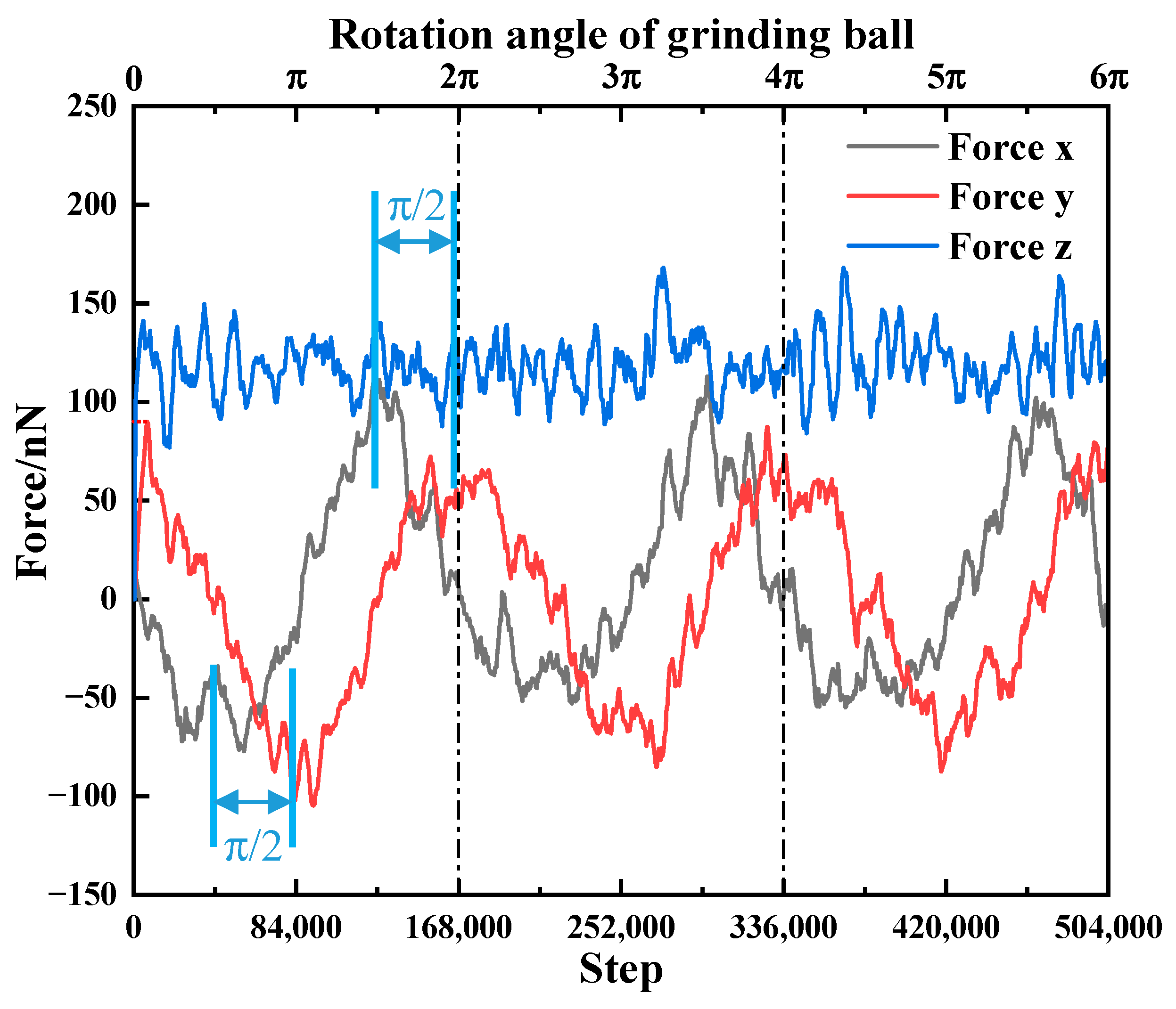
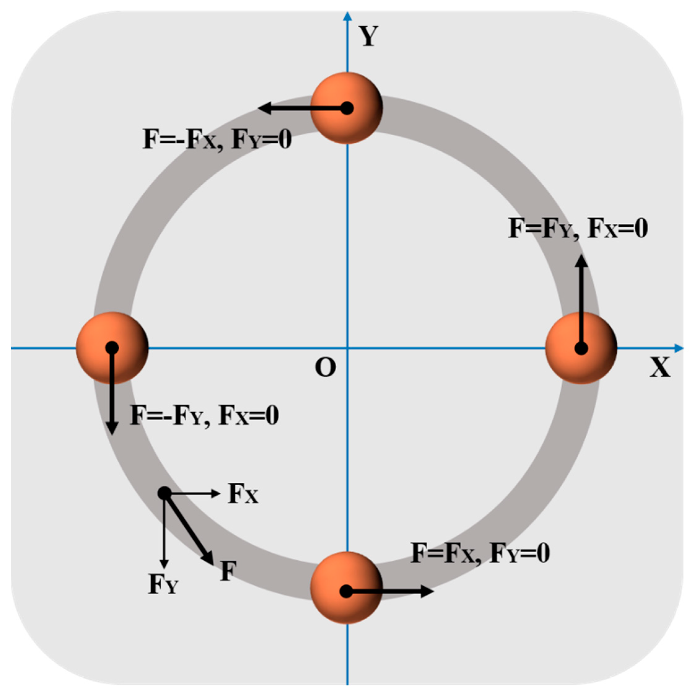
Figure 3 shows the variation law of the force of the grinding ball in the X, Y and Z directions with time steps under rotational friction. As shown in Figure 3, the forces in the X and Y directions exhibit sine and cosine variation characteristics. To deeply understand this type of friction, it is illustrated by the schematic diagram in Figure 4. As shown in Figure 4, when the absolute value of one of the component forces is the maximum, the absolute value of the other component force is zero. Thus, when the grinding ball performs a circular motion, the peak and valley values of the forces in the X and Y directions alternate, and the difference between them is π/2. In addition, when the grinding ball is rubbing on the workpiece under a constant load, the Z-directional force always fluctuates around a certain value due to the discontinuity of the abrasive chip formation.
To accurately analyze the law between the change in friction force and material deformation, the X- and Y-directional forces are combined to obtain the total friction force F f , and the equation is shown in (4):
F f = ( F x ) 2 + ( F y ) 2
where F f is the frictional force; in the X and Y directions, F x and F y represent the component forces, respectively.
Figure 5 shows the dynamic response curves of the friction force and friction coefficient with time steps. The initial friction starts from the nickel surface. As shown in Figure 5, the friction force continues to increase as the grinding ball presses down and creates a rotating motion. Further, after the load-bearing capacity of the material and the downward pressure load of the grinding ball reach equilibrium, the grinding ball no longer moves downward, and the friction force reaches its maximum at this time (position 1 in Figure 5a). Thereafter, the friction force slowly decreases to position 2, which is because the nickel substrate maintains better surface quality during the initial friction, resulting in a reduction in the friction force. Meanwhile, peaks appear near π/2 and 3π/2, respectively. The analysis reveals that the grinding ball is precisely at the two-phase interface at this time, and the peak of the friction force is caused by the accumulation and release of strain energy at the co-grid interface [23]. When the grinding ball undergoes friction in the Ag film region (π/2–3π/2), the friction force first increases and then decreases, which is related to the poor load-bearing capacity of the soft metal Ag. Further analysis reveals that the material removal from the Ag film surface increases at the first friction stage, and the increase in the friction force is associated with a large pileup of abrasive chips in front of the grinding ball movement. However, the fluctuation of the friction force is more dramatic during the repeated friction stages, which is caused by the unevenness of the grinding groove surface.
In addition, the friction reduction effect of Ag as the lubricating primitive for this simulation on the nickel substrate is usually evaluated by the friction coefficient. Therefore, Figure 5b shows the variation law of the friction coefficient with the time steps. It can be seen that the friction coefficient shows periodic fluctuations with the friction, which is related to the model established with a semi-area characteristic. Here, the green regions (A, B and C) show the variation in the friction coefficient tracked in real time on the Ag film surface during the three friction processes. The friction coefficient in the B region seems to be the lowest, followed by the more fluctuating C region, while the A region has the highest and more dramatic fluctuations in the friction coefficient. This suggests that the number of friction laps has a significant influence on the friction coefficient of the Ag film surface. Meanwhile, the peaks at positions 1, 2 and 3 marked in Figure 5b gradually decrease (blue line segment). The analysis reveals that the three positions are exactly at the two-phase interface (the movement of the grinding ball from the Ag to the Ni surface). It shows that repeated friction facilitates the reduction of the friction coefficient in the interface transition zone.
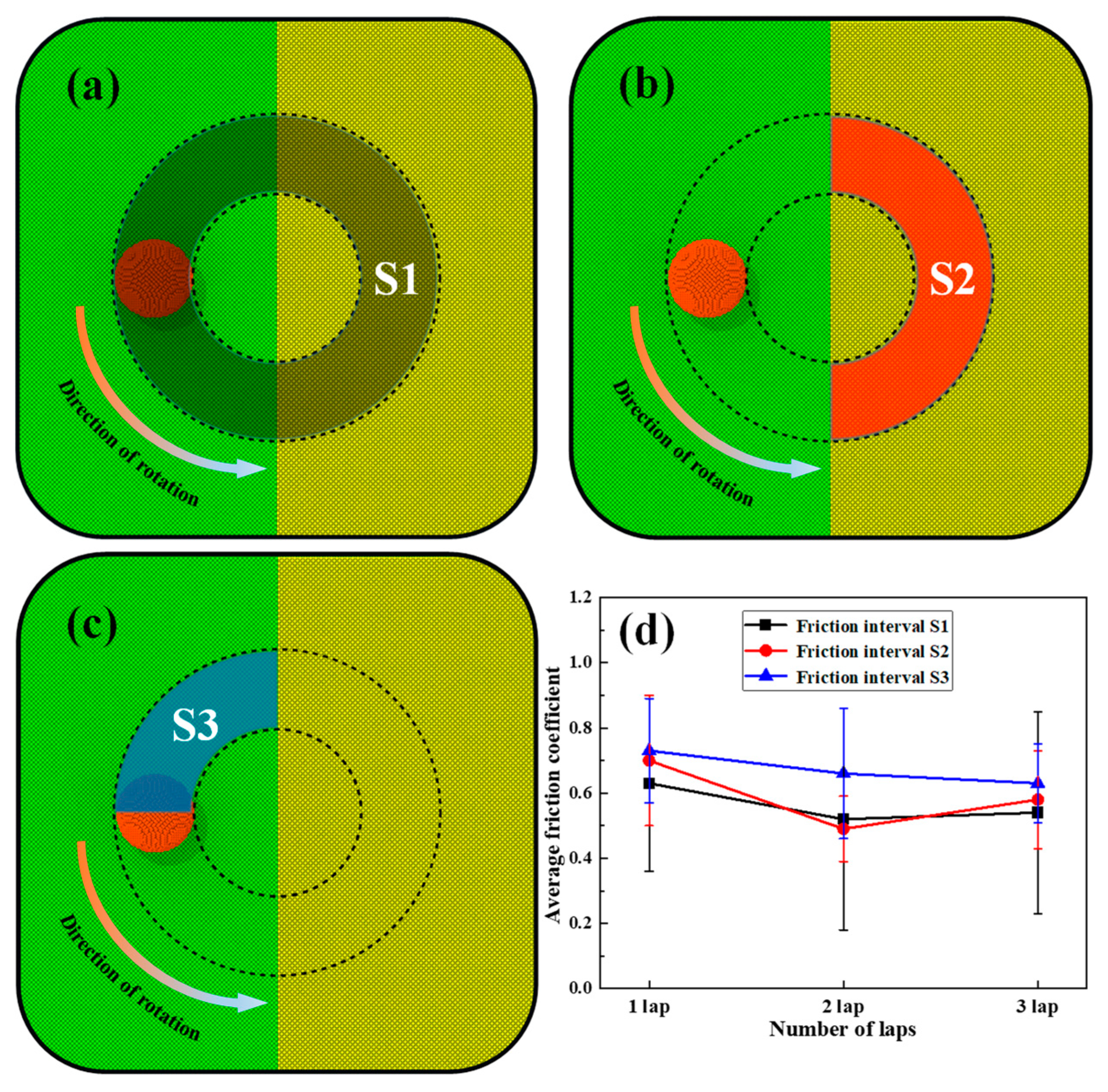
To analyze accurately the variation law of the friction coefficient with the number of friction laps in different friction regions, as shown in Figure 6, the friction region during the friction process is divided into three parts (Figure 6a–c), where interval S1 indicates the friction of the grinding ball on the whole workpiece surface; interval S2 indicates the friction of the grinding ball on the Ag film surface only; and interval S3 indicates the friction of the grinding ball half way from the interface to the nickel surface. The friction coefficient in Figure 5b is converted into the average friction coefficient for the three intervals (Table 3) and plotted in Figure 6d. As shown in Figure 6d, the friction coefficients of interval S1 and interval S2 first decrease and then increase with the increase in the number of friction laps, whereas the average friction coefficient of interval S3 continuously decreases with the increase in the number of friction laps. These results (interval S2 and interval S3) are consistent with the observed phenomena in Figure 5b.
The analysis of the above shows that the higher friction coefficient of the Ag film surface (interval S2) during the first friction stage (Figure 6 and Table 3) is related to the large pileup of abrasive chips during the motion of the grinding ball. Indeed, the large pileup of abrasive chips leads to a gradual increase in the friction force (Figure 5), which in turn causes an increase in the friction coefficient. However, the friction coefficient of the Ag film surface decreases to 0.49 during the second lap of friction. This can be clarified as the following. On the one hand, the weakening of the blocking effect on the grinding ball by the lesser accumulation of abrasive chips at the second friction stage resulted in the reduction of the friction force; on the other hand, the abrasive grooves formed on the Ag film by the first friction act as a slip channel with low shear strength to reduce the resistance of the grinding ball. Thus, the small amount of material removal from the Ag film surface and the formation of the slip channel contribute to the friction reduction and lubrication effect of the Ag film. Moreover, the friction coefficient of the Ag film surface increases to 0.58 as the friction continues (third lap). This is due to the fact that the third friction stage mainly occurs on the nickel substrate below the Ag film, leading to the weakening of the friction-reducing effect on the Ag film.
In addition, it is found that the friction coefficient of interval S3 continuously decreases with the increase in the number of friction laps (Figure 6 and Table 3), which may be related to the migration behavior of Ag atoms at the interface. Therefore, an in-depth analysis of the frictional behavior at the interface is performed. Figure 7 shows the abrasive chip morphology on the interface at the first friction. Among them, Figure 7a shows the abrasive chip morphology at the interface when the grinding ball first moves from the Ni to the Ag surface. Similarly, as the friction continues, the corresponding abrasive chip morphology when the grinding ball moves to the next interface is shown in Figure 7b. From Figure 7a, it can be seen that the grinding ball shows a certain degree of sagging on the biased Ag side, and the height difference between the two-phase transition zone is measured to be 1.6 nm. Meanwhile, comparing Figure 7a,b, it can be observed that there is a significant difference in the abrasive chip morphology at different friction stages. The measured chip heights of 3.5 nm and 6.8 nm for Figure 7a,b, respectively, indicate the continuous accumulation of chip atoms in front of the grinding ball motion. Furthermore, it is noted that the thickness of Ag atoms directly interacting with the grinding ball in Figure 7b is 0.6 nm, which is 50% more than the thickness of Ni atoms (0.3 nm) in Figure 7a. This further indicates that a large number of Ag atoms can reach the Ni surface by migration under the pushing action of the grinding ball.
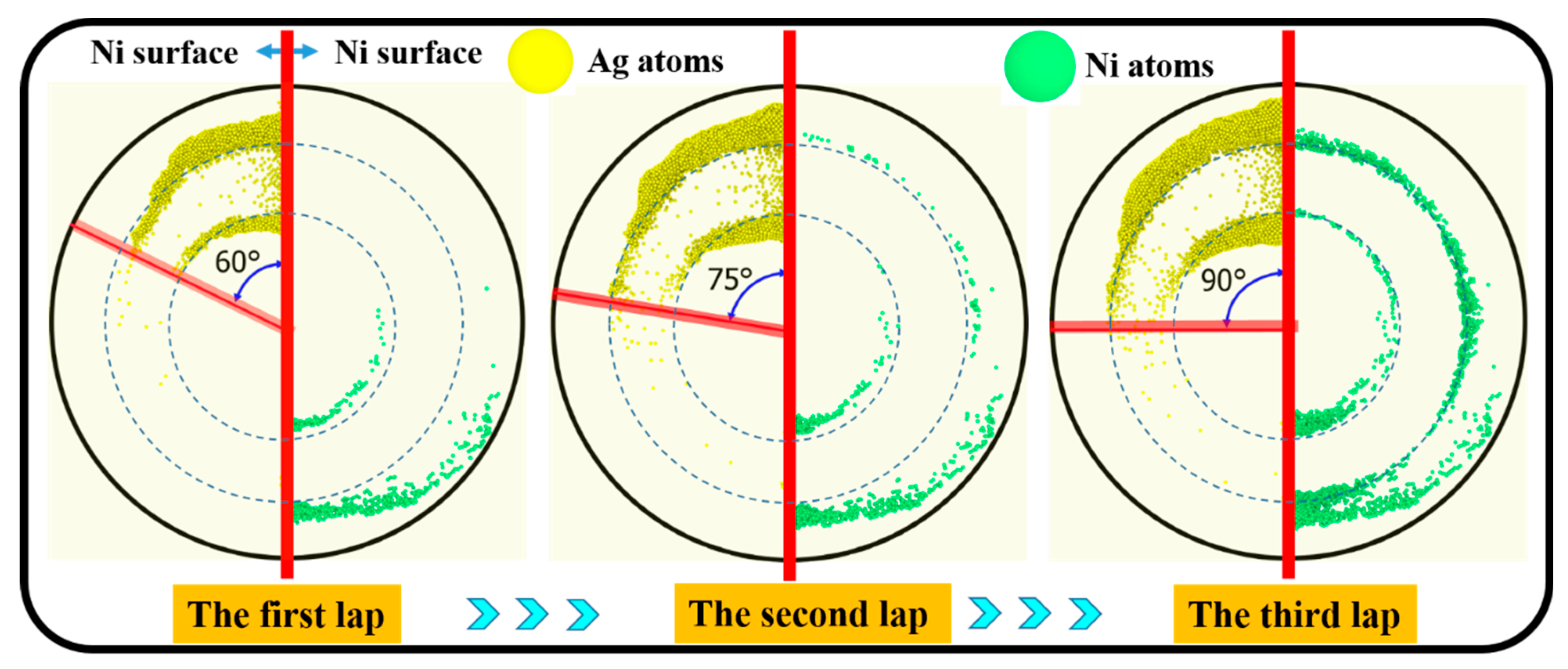
To deeply understand the migration behavior of the workpiece atoms at the interface, the distribution of Ag and Ni atoms migrating towards each other during the friction process is shown in Figure 8. As shown in Figure 8, most of the abrasive atoms are separated by the grinding ball to the sides of the grinding groove during the friction process. Here, the length extended by the Ag atoms migrating on the nickel surface is expressed in terms of the angle swept. Therefore, it can be clearly seen that Ag atoms are heavily aggregated on the nickel surface with friction. Meanwhile, the angles swept by Ag atoms on the nickel surface during the three friction laps were measured to be 60°, 75° and 90°, respectively. This indicates that repeated friction contributes to the migration of Ag atoms. Additionally, it should be emphasized that the large amount of debris (Ag and Ni atoms) that accumulates on both sides of the grinding groove usually results in further hardening of the material.
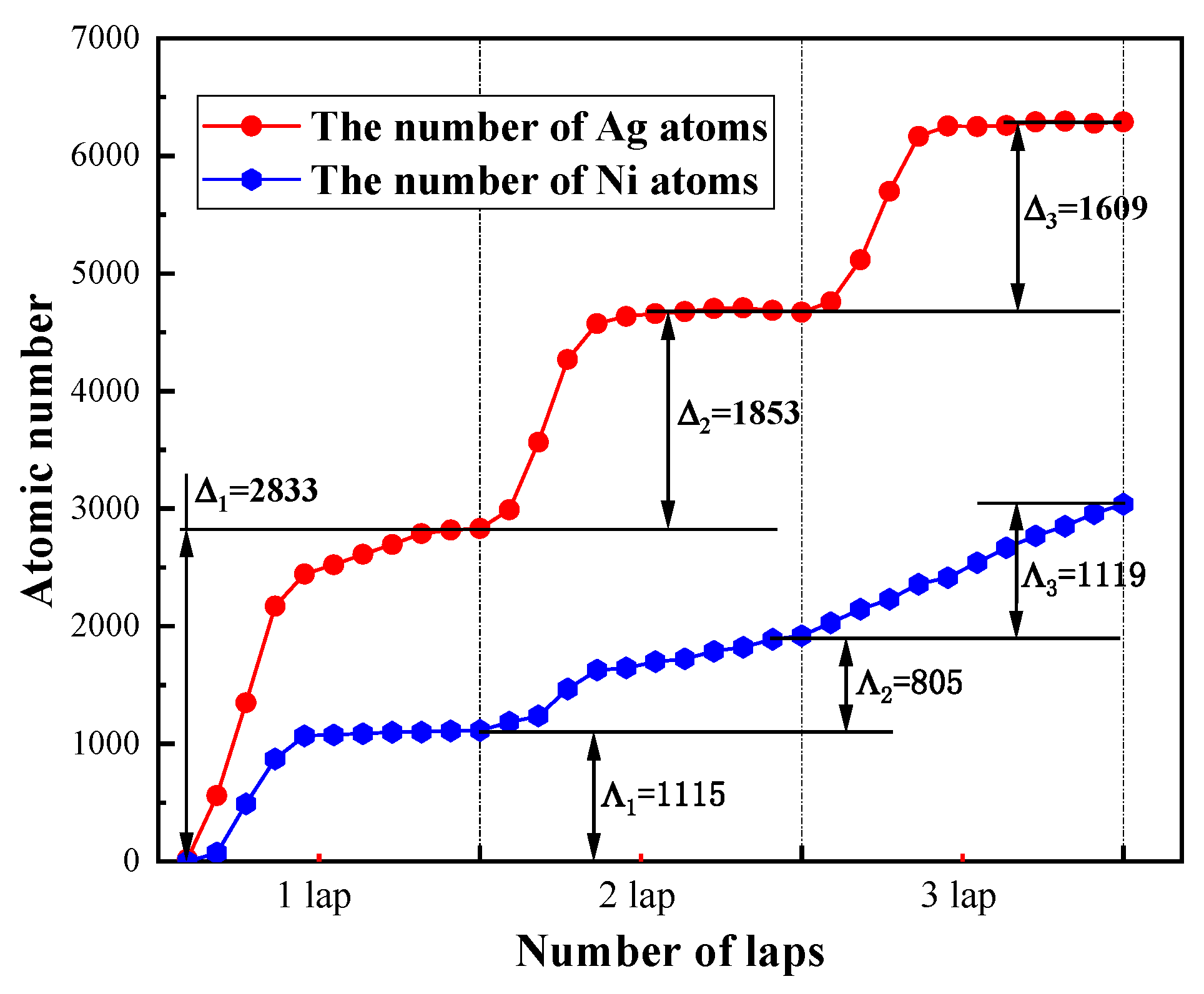
In order to accurately describe the change in the number of Ag atoms migrating during the friction process, the variation in the number of Ag and Ni atoms migrating with the number of friction laps is plotted in Figure 9. As shown in Figure 9, repeated friction leads to an increase in the total number of Ag atoms migrating. Meanwhile, the increments in Ag atoms on the nickel surface during the three friction laps are Δ1 = 2833, Δ2 = 1853 and Δ3 = 1609, respectively, clearly Δ1 > Δ2 > Δ3. This demonstrates that the migration of Ag atoms is most significant quantitatively during the first friction stage, and this quantitative advantage becomes less pronounced with repeated friction. These laws are related to the destruction of the Ag film and the gradual depletion of Ag atoms during repeated friction. However, it is necessary to emphasize that the continuous increase in the number of Ag atoms migrating to the Ni surface plays a key role in the friction reduction of its surface as the friction proceeds, which is the main reason for the decrease in the friction coefficient of interval S3 in Figure 6.
In addition, a similar migration phenomenon of Ni atoms exists on the Ag film. The Ni atoms are in an increasing trend in migration range and number during the three laps of friction (Figure 8). As can be seen from Figure 8, the migration increments in Ni atoms on the Ag film are Λ1 = 1115, Λ2 = 805 and Λ3 = 1119, respectively, and Λ3 > Λ1 > Λ2. This can be explained by the fact that during the first friction stage, the abrasive chips formed on the Ni surface are carried to the Ag film surface by the grinding ball. At this time, the grinding ball only rubs on the Ag film, and has no direct effect on the nickel substrate below the Ag film. When repeated friction is performed, the protective effect of the Ag film on the substrate is weakened, resulting in enhanced damage to the interface by the grinding ball. The Ni atoms are eventually detected as abrasive chips mixed in the Ag film and increase with the number of friction laps. Therefore, from the variation law of Ag atom migration at the interface, repeated friction contributes to the migration of Ag atoms to the Ni surface and decreases the friction coefficient of its surface as the number of migrations increases (Figure 5 and Figure 6). This provides a microscopic insight regarding the understanding of the friction reduction and lubrication behavior of an Ag-containing coating on a Ni substrate at the macroscopic level [57,58,59].

3.2. The Effect of Friction on the Displacement of Workpiece Atoms

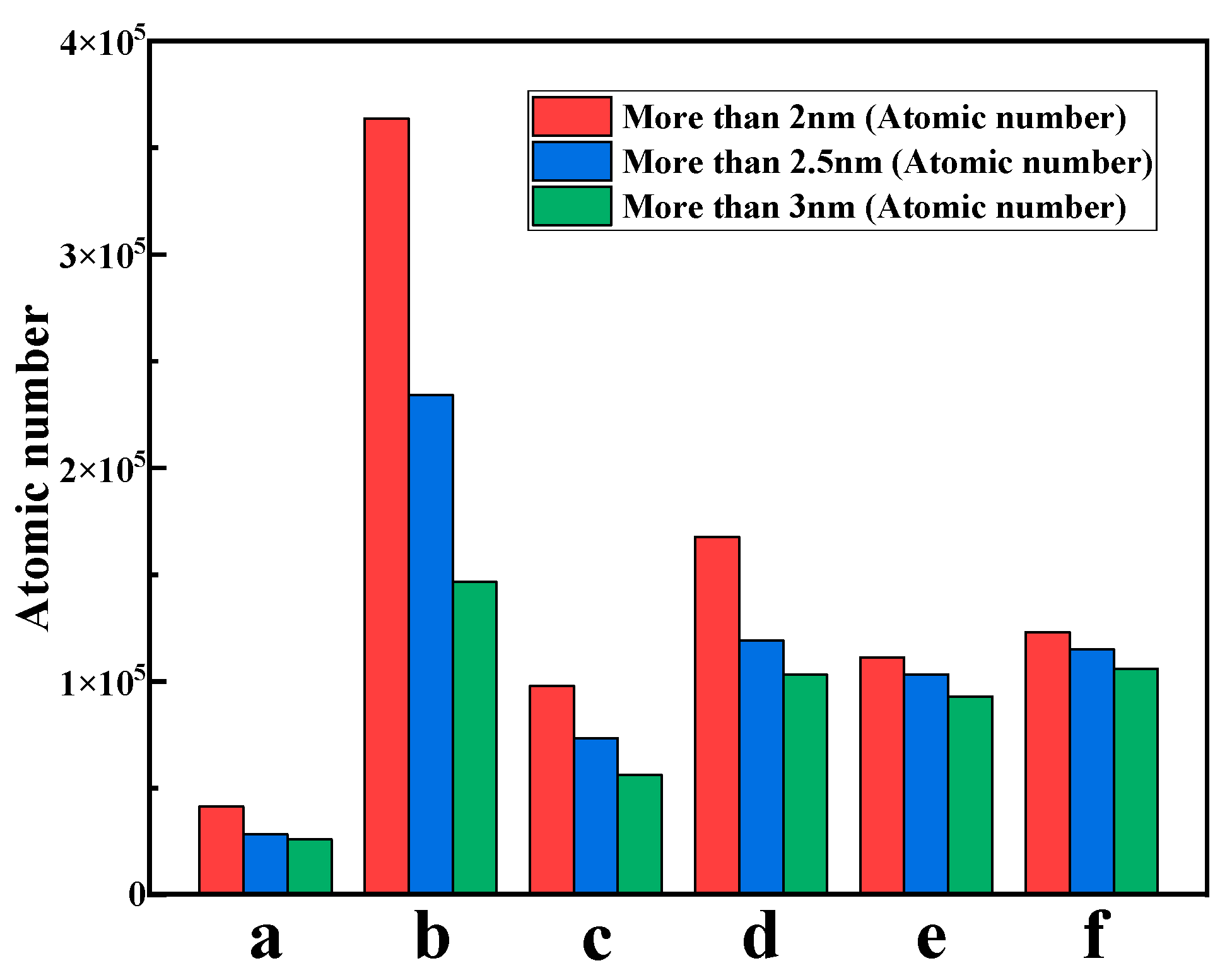
The deformation behavior of the workpiece can be realized by studying the change in atomic displacements. Figure 10 shows the displacement variation during the initial friction process. Here, only atoms with displacements greater than 3 Å are included to eliminate the influence of displacement due to atomic vibration. The letter B indicates the position where the grinding ball is located, and the red arrow indicates the direction of the displacement extension. Moreover, in order to accurately analyze the variation law of the displacement, the number of atoms with displacements exceeding 2 nm, 2.5 nm and 3 nm for each friction moment in Figure 10 was calculated, as shown in Figure 11.
In Figure 10a, the Ni atoms that undergo displacement during the first friction appear only at the abrasion mark. This is related to the stronger resistance of nickel to deformation [23,24]. However, when the grinding ball moves to the interface (position B in Figure 10b), a large range of displaced atoms appears on the Ag film surface (Figure 11b). This indicates that the atomic displacement can be super-conducted to the Ag film surface through the two-phase interface, and also demonstrates that the workpiece is in an energy storage state at this time. After the grinding ball passes through the two-phase interface, the energy stored in the workpiece is partially released and the displaced Ag atoms undergo elastic recovery, resulting in the disappearance of the displaced atoms from the Ag surface (Figure 10c and Figure 11c). At this point, only larger displaced atoms are observed near the wear marks. However, it is noteworthy that the number of displaced atoms on the Ag surface is significantly higher compared to the Ni surface (Figure 11), indicating the significant atomic movement of Ag as a lubricating film during the friction process.
When the grinding ball is in the stage in Figure 10d, the displacement area of the Ag surface continues to increase compared to the stage in Figure 10c. The Ag atoms with large displacements (red atoms) show a band-like distribution along the inner and outer sides of the grinding ball. Meanwhile, the distribution of atoms with large displacements (red atoms) is more pronounced on the outer side, which is due to the larger linear velocity of the outer side. Moreover, the displacement continues to move in the direction of the red arrow and ends at the interface. When the grinding ball is in the stage in Figure 10e, the extension of the displacement is still bounded by the two-phase interface, and no significant displacement occurs on the nickel side, indicating that the interface acts as a barrier to the conduction of the Ag atomic displacement. This is in contrast to the observed super-conduction of displacement in Figure 10b.
When the grinding ball passes through the interface and continues its movement to the stage in Figure 10f, the distribution of displaced atoms on the nickel surface is consistent with the law of Figure 10a. The atoms with large displacement on the outer side of the grinding groove are distributed on the nickel surface, in addition to the Ag surface. This is due to the large accumulation of Ag atoms at the interface (Figure 7b) and their migration to the nickel surface with the pushing of the grinding ball. Therefore, it follows from the quantification results of Figure 10 and Figure 11 that the increase and decrease in the displacement atoms is a concrete manifestation of the plastic deformation and elastic recovery processes.
From the above analysis, it can be seen that Ag atoms possess significant displacement changes. Therefore, it is necessary to analyze in depth the general motion law of Ag atoms during the friction process. In order to facilitate the comparison of the effect of the substrate on the displacement of Ag atoms, the whole workpiece was intercepted in the X-Z plane, and the grinding ball was always at the same position on the Ag surface during the repeated friction stages, as shown in Figure 12.
As can be seen in Figure 12, repeated friction has a significant impact on the displacement of Ag atoms. The analysis reveals that the Ni atoms that undergo large displacement during the friction process are only at the edge of the grinding groove. However, as the friction proceeds, more atoms colored green in the typical region of the Ag film are observed, indicating that repeated friction assists the movement of more Ag atoms. Meanwhile, no extensive movement of Ni atoms is observed at the two-phase interface, which is consistent with the analysis in Figure 10.
Additionally, the variation in the atomic displacement vector of Ag on the inner side of the grinding ball in Figure 12 is analyzed, where the red arrows indicate the direction and magnitude of the atomic displacement. During the initial friction (Figure 12a), the displacement of the Ag atoms in the typical region changes regularly. It is clear from the schematic diagram that the change in displacement of the Ag atoms can be divided into different regions. This is caused by the discontinuity in the interaction between the Ag atoms. This discontinuity is reflected in two aspects. On the one hand, the squeezing effect of the grinding ball is exerted on the Ag atoms on the inside and, as can be seen by the direction of the displacement, this squeezing effect dominates. On the other hand, the interface also acts as a force on the motion of the Ag atoms. Thus, the combined effect of the two factors eventually leads to an increase in the number of Ag atoms with different displacements. However, during repeated friction, the distribution regions of different displacements gradually decrease (Figure 12b,c), and the number of Ag atoms displaced increases along the horizontal direction. This is because the repeated friction adjusts the Ag atoms more towards the equilibrium position.
In addition, the motion of the Ag atoms in Figure 12 was further investigated. The X and Z displacement components of the Ag atoms on the inner side of the grinding ball were extracted and scatter plots were drawn. As shown in Figure 13, the majority of Ag atoms are distributed in the negative half-axis of the X displacement, indicating that the direction of atomic motion coincides with the direction of extrusion of the grinding ball to the left. Meanwhile, the displacements of almost all the atoms in the X direction are larger than those in the Y direction, illustrating that the motion of the Ag atoms is mainly transverse deformation. This is consistent with the analysis results in Figure 12, i.e., the squeezing effect of the grinding ball on the Ag atoms is the main reason for the deformation of the Ag film. Moreover, in Figure 13a, the scattering points are almost all below the 45° line. This indicates that the displacement direction of the atoms does not coincide with the slip direction of the crystalline Ag, which is also observed in the machining simulation of single-crystal nickel [22].
However, when the second friction is performed (Figure 13b), the displacement in the Z direction increases, which indicates a tendency for the Ag atoms to move toward the Ag film surface. This is consistent with the tendency of Ag atoms to diffuse toward the surface in Figure 12b. In previous friction experiments, Ag particles were able to disperse and coat the worn surface under the extrusion of high stress and friction heat, thus providing excellent lubrication to the substrate [60]. Here, the squeezing action of Ag atoms by the grinding ball and the migration behavior at the interface are further illustrated at the atomic scale. Meanwhile, the majority of the atoms in Figure 13b are dispersed on the 45° line, which indicates plastic deformation due to the movement of Ag atoms along the slip plane of the crystal. Furthermore, when the third friction step is performed (Figure 13c), the displacement in the Z direction is maintained near its zero value, which is a result of the elastic recovery of the Ag atoms. At this point, significant atomic displacements appear only in the negative direction of the X axis, indicating that the Ag atoms are easier to move along the horizontal direction under repeated squeezing.

3.3. Variation in Internal Defects of the Workpiece with Friction

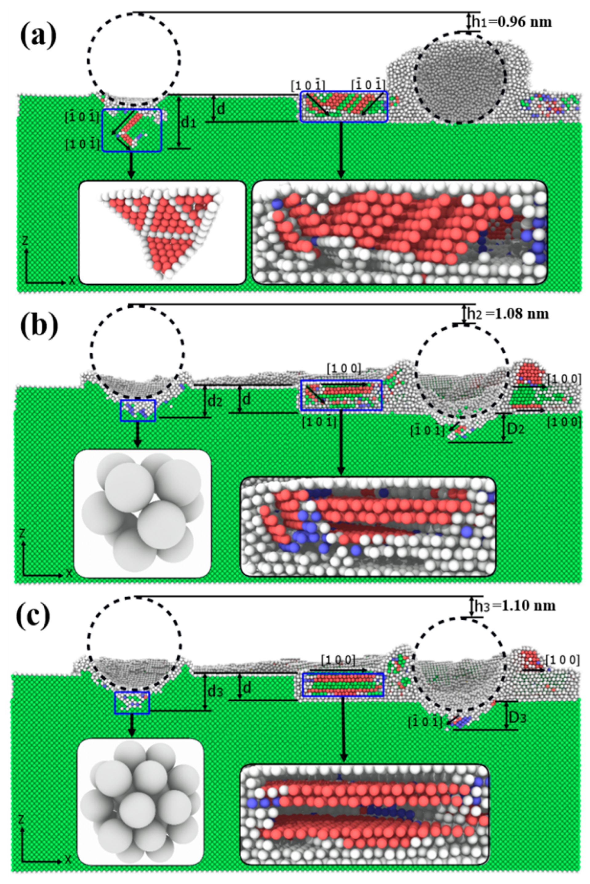
Figure 14 shows the morphology of the inside of the workpiece during friction. Here, the structure types of the crystals are identified using the common neighborhood analysis method in the OVITO visualization software [61], where green represents perfect FCC atoms, red represents HCP atoms, blue represents BCC atoms, and white represents surface and defective atoms of unknown structure. As shown in Figure 14, the depth difference of the wear marks and the depth and direction of the defect extension are marked and measured, respectively.
As shown in Figure 14a, during the first friction step, the difference in the depth of the wear marks measured at both ends of the workpiece is h1 = 0.96 nm, which is caused by the difference in the resistance to deformation of the two materials. When the friction is repeated, the difference in the depth of the wear marks is measured as h2 = 1.08 nm and h3 = 1.10 nm, respectively, which is obviously h2 < h3. This is because, during the second friction stage, the motion of the grinding ball is only near the two-phase interface, and the strengthening of the interface causes the removal of the material to become difficult. However, the difference in the depth of the wear marks increases at the third friction stage, which is due to the second friction stage causing a broken ring at the interface, resulting in the loss of the strengthening effect. Eventually, the removal of the material by the grinding ball becomes apparent.
In addition, friction has a significant impact on the evolution of defects inside the workpiece. As shown in Figure 14a, during the first friction step, defects (HCP) form inside the nickel substrate on its intrinsic stacking fault. However, the extreme susceptibility of Ag to intergranular slip leads to more defects along the orthogonal direction on the Ag film [62]. Meanwhile, the defects are not extended to the interior of the nickel substrate due to the hindrance of the two-phase interface. However, the repeated friction (Figure 14b,c) leads to the formation of more atomic clusters with an amorphous structure compared to the first friction. Meanwhile, the repeated friction causes the formation of defects inside the Ni substrate below the Ag film, and the defect types are mainly HCP, BCC and defective atoms of unknown structure.
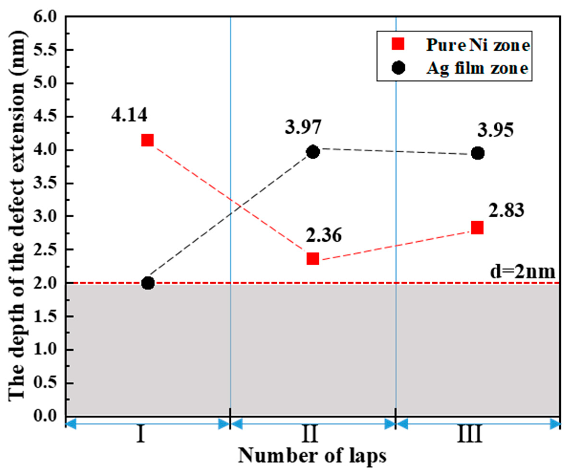
Additionally, the extension depth of the defect inside the Ni substrate during the friction process is measured and plotted in Figure 15. As shown in Figure 15, it can be clearly seen that a significant change in the extension depth of the defect occurs with the increase in the number of friction laps. On the pure Ni surface (at the left abrasion mark), the depths of defect extension at the first and second friction stages are measured to be d1 = 4.14 nm and d2 = 2.36 nm, respectively; obviously, d1 > d2. This is because the large structural defects produced by the first friction step undergo elastic recovery and energy release during the repeated friction stages, causing the unstable, large defect atoms to reconstruct and eventually form more stable defect structures (Figure 14b).
When the third friction step is performed, the extension depth of the defect (d3 = 2.83 nm) increases slightly compared to the second friction step. This is attributed to the surface hardening caused by the second friction step. The hardened surface acts as a protective barrier to weaken the direct damage of the grinding ball to the interior of the substrate. Moreover, combining Figure 14 and Figure 15, it is found that no defects are produced under the Ag film at the first friction stage, which is due to the protection of the Ni substrate by the two-phase interface. However, during repeated friction, some defects are formed on the Ni substrate due to the destruction of the interface. During the second and third friction processes, the depth of defect extension in the substrate is measured as D2 = 3.97 nm and D3 = 3.95 nm. Apparently, the difference between D2 and D3 (difference of 0.02 nm) is within its error range, indicating that repeated rubbing leads to surface hardening, which allows the formation and extension of defects inside the workpiece in a steady-state phase, which is significantly different from the generation of large defects by the first stage of friction. It is noteworthy that the defects inside the Ag film show a significant change in the extension direction during the friction process. As can be seen in Figure 14, the inclined intrinsic stacking fault gradually evolves into a horizontal stacking fault with repeated friction. This is also observed in the Cu/Ni multilayer model with a similar layer fault change [63]. According to the explanation of Fu et al. [63], the horizontal layer-by-layer motion of atoms affects the crystal orientation and thus contributes to the stacking faults’ motion. Hence, the horizontal movement of Ag atoms increases layer-by-layer with repeated squeezing of the Ag film by the grinding ball, leading to the disappearance of the intrinsic stacking fault and the formation of more horizontal stacking faults. Moreover, the slip of horizontal stacking faults can release the internal stresses, and their presence near the interface facilitates the hardening of multilayers.
Figure 16 shows the evolution of defects inside the nickel substrate at the first friction stage. The different types of atoms were colored using the common neighborhood analysis (CNA) method [64] and the perfect FCC atoms in the crystals were removed. As shown in Figure 16a, a large structural defect (HCP) is formed in the subsurface layer at the initial stage of friction, and a large number of amorphous atoms (defects of unknown structure) and a small number of BCC atoms are collected at the lower surface near the abrasion marks. As the friction proceeds, the number of amorphous atoms decreases and the volume of the defect continues to increase, as shown in Figure 16b. This indicates that the workpiece is in a state of energy storage at the initial stage of friction, and the stability of the large structural defect is poor. When the grinding ball imparts a continuous energy input to the interior of the workpiece, a significant stacking fault change is formed, which results in the transformation of more amorphous atoms into HCP (Figure 16b). When the friction enters the stabilization stage, the damage inside the workpiece by the grinding ball is weakened. Meanwhile, the stacking fault atoms under larger deformation undergo an elastic recovery process, leading to the evolution of the large-volume defect (Figure 16b) into a smaller-volume stacking fault structure and a “V”-shaped dislocation loop, as shown in Figure 16c. Therefore, the evolution of the defect structure in Figure 16 is a gradual and stable development process [65].
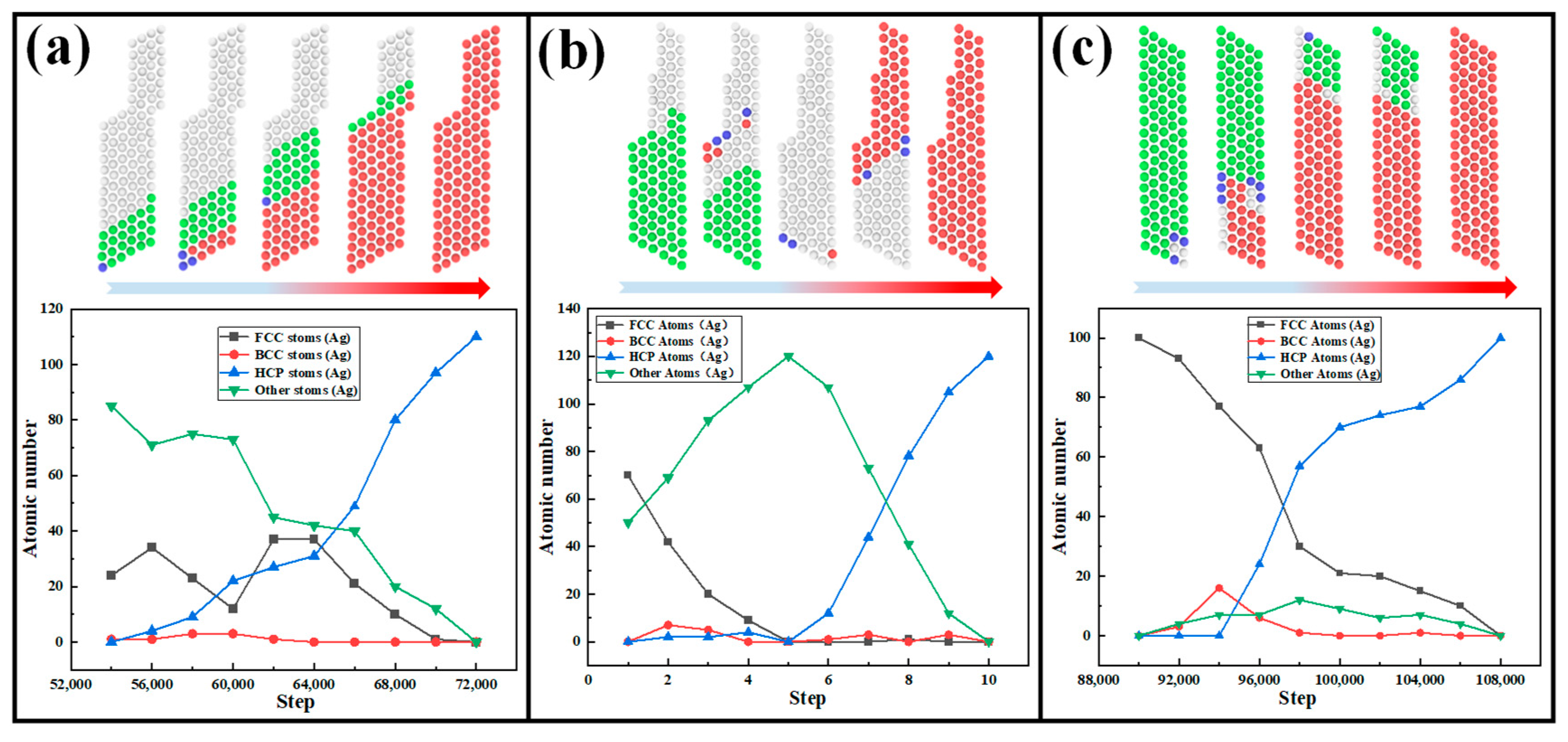
Throughout the friction process, the Ag film is highly susceptible to stacking faults inside (Figure 14), while the large structural defects (HCP) formed undergo slip reconstruction as the friction proceeds. Therefore, the HCP structure formed in the Ag film due to friction is classified into three different types of changes, and the phase transition is analyzed by the atomic tracing method, as shown in Figure 17. Furthermore, the number of atoms (e.g., FCC, BCC, HCP and other atoms) of the three types at different time steps is calculated, as shown in Figure 18.
In Figure 17, type 1, type 2 and type 3-A are considered as stacking faults with a horizontal orientation, and their formation is closely related to the horizontal displacement of Ag atoms (Figure 12). In Figure 18a, the corresponding type 1 is a horizontal stacking fault at the two-phase interface. At the initial stage of HCP structure formation, defective atoms of unknown structure at the interface are the majority and a small fraction arises from FCC atoms. Meanwhile, a very small amount of BCC atoms undergo interconversion between amorphous, HCP and FCC atoms. As the grinding ball squeezes the interface, part of the perfect FCC structure undergoes a phase transition to form HCP, while the amorphous atoms recover by elasticity to form the original FCC. As the friction continues, more amorphous atoms recover to FCC, accompanied by the transformation of FCC to a HCP structure. Through this changing law, type 1 is finally formed. It is important to emphasize that the horizontal stacking faults formed at the interface are helpful for the strengthening of the interface [63].
Figure 18b corresponds to type 2 in Figure 17. It can be clearly seen that type 2 is mainly distributed in the abrasive chips on the surface of the Ag film, and this type of HCP structure has significant plastic deformation at the initial stage of formation. By tracking this phase transition process, it is found that perfect FCC is dominant in the initial stage of HCP structure formation and a small amount of surface amorphous atoms are present. As the friction continues, the FCC structure tends to transform more into amorphous atoms, accompanied by the transformation of individual BCC and HCP. When the disruption of the FCC crystal structure by the grinding ball intensifies, almost all of the FCC undergoes phase transformation to form amorphous atoms. This is undoubtedly true, because this area belongs to the abrasive chip accumulation zone. The grinding ball causes severe damage to the FCC structure through material removal and chip diversion.
The transformation process of type 3 corresponds to Figure 18c. As can be seen in Figure 17, type 3 is subdivided into type 3-A and type 3-B, where type 3-A is mainly located near the inner side of the grinding groove, but it is distinct from type 2 in the region of abrasive chips, and type 3-B is formed mainly at a location away from the friction. Therefore, in the early stage of HCP formation, the area near the abrasion marks and away from the abrasion marks is almost entirely a perfect FCC structure (Figure 18c). As the friction proceeds, the action of the grinding ball on the FCC atoms around the abrasion marks gradually intensifies. When the squeezing action reaches the critical value of the phase transition, the FCC near the abrasion marks first undergoes the phase transition, leading to the formation of type 3-A. As the friction continues, the conduction of displacement and the continuous input of energy causes a stacking fault to develop away from the abrasion marks, leading to a phase transition in the FCC to form HCP, as shown in Figure 17, for type 3-B. It is noteworthy that type 3-A, located near the wear marks, extends along the horizontal direction, while type 3-B, which is located away from the friction zone, extends the intrinsic stacking fault. This is mainly caused by the displacement of the Ag film. The formation of type 3-A is attributed to the movement of Ag atoms along the horizontal direction (Figure 14). In contrast, for type 3-B, being far from the friction zone, the squeezing effect is gradually weakened during the Ag atomic displacement transfer. Therefore, the smaller forces can only influence the crystalline Ag to carry out the inclined intrinsic stacking fault, and thus the phase transition from FCC to HCP occurs.
To understand more deeply the effect of repeated friction on the three HCP structures, in Figure 17, the atomic numbers of the different structures (FCC, BCC, HCP and others) are presented for the three types (type 1, type 2 and type 3) undergoing phase transitions during the three-loop friction process, as shown in Figure 19. Figure 19a shows the variation in the number of atoms of different structures in the three-loop friction for type 1. It is clear that the amorphous atoms are mainly dominant at the two-phase interface, followed by FCC and HCP atoms, while BCC atoms have the smallest number. Moreover, it is noted that the number of horizontal stacking faults (type 1) at the interface increases with the number of friction laps, indicating that repeated friction contributes to the formation of more horizontal stacking faults. Figure 19b shows the variation in the atomic numbers of different structures with the number of friction circles during the phase transition of type 2. Since type 2 is in the abrasive chip pileup zone, more defective atoms of unknown structure are detected, followed by HCP atoms with horizontal stacking faults. However, the destructive action of the grinding ball is the main reason for the low number of perfectly structured FCC atoms (Figure 19b). Additionally, for type 3, the variation law of the number of atoms with the number of friction circles for the different structures is shown in Figure 19c. As depicted in Figure 18c, the formation of type 3 is mainly transformed between FCC and HCP. As a result, the number of atoms in FCC and HCP is always higher in all three laps. It is noteworthy that all three types of HCP atoms show a significant increase when rubbing in the second lap and still maintain a high number of atoms during the third lap. Therefore, the continuous frictional action increases the number of defects inside the Ag film and intensifies the hardening of the Ag film.

4. Conclusions

The molecular dynamics method was used to simulate the nano-friction process of a diamond grinding ball on nickel-based Ag film composites. By systematically investigating the frictional wear mechanism of nickel-based Ag film composites, the following conclusions were drawn.
  • Friction has a significant effect on the mechanical properties of the workpiece. At the first friction stage, a large amount of abrasive chip pileup in front of the grinding ball movement leads to a high friction force and friction coefficient on the Ag film surface. During the second friction stage, the Ag film exerts a better friction reduction effect due to the formation of slip channels with low shear strength. Moreover, the migration of Ag atoms at the two-phase interface contributes to the friction reduction and lubrication of the nickel surface.
  • The Ag film has more significant atomic displacement than the Ni substrate. The displacement of Ni atoms occurs only near the abrasion mark, while Ag atoms near the friction zone eventually become horizontally displaced with repeated friction, which assists the interlayer flow of Ag. Meanwhile, the two-phase interface plays a suppressive role in the transfer of Ag atomic displacements.
  • As friction proceeds, the large structural defects (HCP) in the nickel matrix gradually transform into amorphous and more stable small structural defects. In addition, the Ag film has a more active slip system inside than the nickel substrate. In particular, the defects near the friction zone gradually transform from intrinsic stacking faults to horizontal stacking faults with repeated friction. This is attributed to the formation of horizontal stacking faults promoted by more horizontally oriented moving Ag atoms.
  • The extension of defects inside the Ag film is hindered by the two-phase interface. Meanwhile, the horizontal stacking fault structure formed at the two-phase interface helps in the strengthening of the interface.

Author Contributions

Methodology, X.W.; formal analysis, W.C. (Wenbang Chen), Z.Z., M.Z. and X.W.; data curation, W.C. (Wenbang Chen), Z.Z., M.Z. and X.W.; writing—original draft preparation, W.C. (Wenbang Chen) and W.C. (Weihua Chen); writing—review and editing, W.C. (Wenbang Chen), W.C. (Weihua Chen), T.S. and D.Q. All authors have read and agreed to the published version of the manuscript.

Funding

This research was funded by the National Natural Science Foundation of China (52265025).

Institutional Review Board Statement

Not applicable.

Informed Consent Statement

Informed consent was obtained within the article.

Data Availability Statement

Data can be provided on request due to privacy or ethical restrictions.

Conflicts of Interest

The authors declare no conflict of interest.

References

  1. Ma, Z.; Pei, Y.L.; Luo, L.; Qin, L.; Li, S.S.; Gong, S.K. Partitioning behavior and lattice misfit of γ/γ′ phases in Ni-based superalloys with different Mo additions. Rare Met. 2020, 40, 920–927. [Google Scholar] [CrossRef]
  2. Zhao, Y.; Zhang, J.; Song, F.; Zhang, M.; Luo, Y.; Zhao, H.; Tang, D. Effect of trace boron on microstructural evolution and high temperature creep performance in Re-contianing single crystal superalloys. Proc. Nat. Sci. Mater. Int. 2020, 30, 371–381. [Google Scholar] [CrossRef]
  3. Tian, Y.; Yang, R.; Gu, Z.; Zhao, H.; Wu, X.; Dehaghani, S.T.; Chen, H.; Liu, X.; Xiao, T.; McDonald, A. Ultrahigh cavitation erosion resistant metal-matrix composites with biomimetic hierarchical structure. Compos. B Eng. 2022, 234, 109730. [Google Scholar] [CrossRef]
  4. Li, L.; He, K.; Sun, S.; Yang, W.; Yue, Z.; Wan, H. High-temperature friction and wear features of nickel-based single crystal superalloy. Tribol. Lett. 2020, 68, 1–12. [Google Scholar] [CrossRef]
  5. Duan, W.; Sun, Y.; Liu, C.; Liu, S.; Li, Y.; Ding, C.; Ran, G.; Yu, L. Study on the formation mechanism of the glaze film formed on Ni/Ag composites. Tribol. Int. 2016, 95, 324–332. [Google Scholar] [CrossRef]
  6. Zhang, T.; Lan, H.; Huang, C.; Yu, S.; Du, L.; Zhang, W. Preparation and characterizations of nickel-based composite coatings with self-lubricating property at elevated temperatures. Surf. Coat. Technol. 2016, 294, 21–29. [Google Scholar] [CrossRef]
  7. Ye, F.; Lou, Z.; Wang, Y.; Liu, W. Wear mechanism of Ag as solid lubricant for wide range temperature application in micro-beam plasma cladded Ni60 coatings. Tribol. Int. 2022, 167, 107402. [Google Scholar] [CrossRef]
  8. Zhen, J.; Cheng, J.; Tan, H.; Sun, Q.; Zhu, S.; Yang, J.; Liu, W. Investigation of tribological characteristics of nickel alloy-based solid-lubricating composites at elevated temperatures under vacuum. Friction 2020, 9, 990–1001. [Google Scholar] [CrossRef]
  9. Liu, Y.; Liu, X.; Zhang, X.; Chen, X.; Zhang, J.; Jing, L.; Wu, Y.; Yu, S. Tribological properties and self-lubrication mechanism of in-situ grown graphene reinforced nickel matrix composites in ambient air. Wear 2022, 496, 204308. [Google Scholar] [CrossRef]
  10. DellaCorte, C.; Lukaszewicz, V.; Valco, M.J.; Radil, K.; Heshmat, H. Performance and durability of high temperature foil air bearings for oil-free turbomachinery. Tribol. Trans. 2000, 43, 774–780. [Google Scholar] [CrossRef]
  11. Dellacorte, C. The effects of substrate material and thermal processing atmosphere on the strength of PS304: A high temperature solid lubricant coating. Tribol. Trans. 2003, 46, 361–368. [Google Scholar] [CrossRef]
  12. Sun, H.; Wan, S.; Yi, G.; Yang, J.; Bai, L.; Shi, P.; Cheng, J. Friction and wear behaviors of NiAl-Bi2O3-Ag-Cr2O3 composite coating in the thermal cycle of RT-800 °C. Tribol. Int. 2021, 159, 106957. [Google Scholar] [CrossRef]
  13. Sun, H.; Yi, G.; Wan, S.; Huang, H.; Wang, W.; Zhu, S.; Yang, J. Improving the tribological properties of plasma sprayed NiAl-Bi2O3-Ag-Cr2O3 composite coatings by hot isostatic pressing. Ceram. Int. 2022, 48, 16529–16543. [Google Scholar] [CrossRef]
  14. Sun, B.; Ding, F.; Qiu, B.; Zhao, Y.; Guo, J. High temperature tribological properties of NiAl-Ag2Mo2O7 composite coatings prepared by spark plasma sintering. Surf. Coat. Technol. 2023, 456, 129290. [Google Scholar] [CrossRef]
  15. Li, J.; Tian, Y.; Fang, Q. Molecular dynamics simulation of friction, lubrication, and tool wear during nanometric machining. In Machining and Tribology; Elsevier: Amsterdam, The Netherlands, 2022; pp. 187–211. [Google Scholar]
  16. Aida, H.; Doi, T.; Takeda, H.; Katakura, H.; Kim, S.; Koyama, K.; Yamazaki, T.; Uneda, M. Ultraprecision CMP for sapphire, GaN, and SiC for advanced optoelectronics materials. Curr. Appl. Phys. 2012, 12, S41–S46. [Google Scholar] [CrossRef]
  17. Belak, J.F.; Stowers, I.F. A molecular dynamics model of the orthogonal cutting process. Proc. Am. Soc. Prec. Eng. 1990, 259, 76–79. [Google Scholar]
  18. Goel, S.; Kovalchenko, A.; Stukowski, A.; Cross, G. Influence of microstructure on the cutting behaviour of silicon. Acta Mater. 2016, 105, 464–478. [Google Scholar] [CrossRef] [Green Version]
  19. Zhang, L.; Tanaka, H. Atomic scale deformation in silicon monocrystals induced by two-body and three-body contact sliding. Tribol. Int. 1998, 31, 425–433. [Google Scholar] [CrossRef]
  20. Zhang, L.; Zhao, H.; Dai, L.; Yang, Y.; Du, X.; Tang, P.; Zhang, L.J.R.A. Molecular dynamics simulation of deformation accumulation in repeated nanometric cutting on single-crystal copper. RSC Adv. 2015, 5, 12678–12685. [Google Scholar] [CrossRef]
  21. Hao, Z.; Cui, R.; Fan, Y.; Lin, J. Diffusion mechanism of tools and simulation in nanoscale cutting the Ni-Fe-Cr series of Nickel-based superalloy. Int. J. Mech. Sci. 2019, 150, 625–636. [Google Scholar] [CrossRef]
  22. Zhu, Z.; Peng, B.; Feng, R.; Wang, L.; Jiao, S.; Dong, Y. Molecular dynamics simulation of chip formation mechanism in single-crystal nickel nanomachining. Sci. China. Technol. Sci. 2019, 62, 1916–1929. [Google Scholar] [CrossRef]
  23. Zhu, Z.; Jiao, S.; Wang, H.; Wang, L.; Zheng, M.; Zhu, S.; Cheng, J.; Yang, J. Study on nanoscale friction and wear mechanism of nickel-based single crystal superalloy by molecular dynamics simulations. Tribol. Int. 2022, 165, 107322. [Google Scholar] [CrossRef]
  24. Zheng, M.; Qu, D.; Wei, X.; Zhang, Z.; Zhu, Z.; Wang, L.; Chen, W. Molecular dynamics study on the nanoscale repeated friction and wear mechanisms of TiC/Ni composites. Appl. Phy. A 2022, 128, 1–18. [Google Scholar] [CrossRef]
  25. Zheng, M.; Zhang, Z.; Zhu, Z.; Qu, D.; Chen, W.; Wu, Z.; Wang, L.; Ma, X. Molecular dynamics study of the repetitive friction mechanism of nickel-based single crystals in an aqueous environment. Phys. Scr. 2023, 98, acba5e. [Google Scholar] [CrossRef]
  26. Fang, Q.H.; Wang, Q.; Li, J.; Zeng, X.; Liu, Y.W. Mechanisms of subsurface damage and material removal during high speed grinding processes in Ni/Cu multilayers using a molecular dynamics study. RSC Adv. 2017, 7, 42047–42055. [Google Scholar] [CrossRef] [Green Version]
  27. Li, J.; Fang, Q.; Liu, Y.; Zhang, L. A molecular dynamics investigation into the mechanisms of subsurface damage and material removal of monocrystalline copper subjected to nanoscale high speed grinding. Appl. Surf. Sci. 2014, 303, 331–343. [Google Scholar] [CrossRef]
  28. Zhou, A.; Liu, X.B.; Wang, Q.; Zhang, S.Y.; Meng, Y.; Zhou, H.B.; Zhang, S.H. Investigation of nano-tribological behaviors and deformation mechanisms of Cu-Ni alloy by molecular dynamics simulation. Tribol. Int. 2023, 180, 108258. [Google Scholar] [CrossRef]
  29. Doan, D.Q.; Fang, T.H.; Chen, T.H. Nanomachining characteristics of textured polycrystalline NiFeCo alloy using molecular dynamics. J. Manuf. Process. 2022, 74, 423–440. [Google Scholar] [CrossRef]
  30. Karkalos, N.E.; Markopoulos, A.P. Determination of the efficiency of hot nano-grinding of mono-crystalline fcc metals using molecular dynamics method. Micromachines 2022, 13, 415. [Google Scholar] [CrossRef]
  31. Zhao, P.; Zhao, B.; Pan, J.; Wu, J. Superimpose mechanism of surface generation process in grinding of monocrystalline silicon using molecular dynamics simulation. Mater. Sci. Semicond. Process. 2022, 147, 106684. [Google Scholar] [CrossRef]
  32. Hu, Z.; Chen, Y.; Lai, Z.; Yu, Y.; Xu, X.; Peng, Q.; Zhang, L. Coupling of double grains enforces the grinding process in vibration-assisted scratch: Insights from molecular dynamics. J. Mater. Process. Technol. 2022, 304, 117551. [Google Scholar] [CrossRef]
  33. Karkalos, N.E.; Markopoulos, A.P.; Kundrák, J. Molecular dynamics model of nano-metric peripheral grinding. Procedia CIRP 2017, 58, 281–286. [Google Scholar] [CrossRef]
  34. Karkalos, N.E.; Markopoulos, A.P. Molecular dynamics simulation of nano-grinding with multiple abrasive grains. Solid State Phenom. 2017, 261, 115–120. [Google Scholar]
  35. Duan, N.; Yu, Y.; Wang, W.; Xu, X. Analysis of grit interference mechanisms for the double scratching of monocrystalline silicon carbide by coupling the FEM and SPH. Int. J. Mach. Tools. Manuf. 2017, 120, 49–60. [Google Scholar] [CrossRef]
  36. Meng, X.; Yue, H.; Wu, W.; Dai, H. Simulation of abrasive polishing process of single crystal silicon based on molecular dynamics. Int. J. Adv. Manuf. Technol. 2022, 121, 7195–7211. [Google Scholar] [CrossRef]
  37. Bian, Z.; Gao, T.; Gao, Y.; Wang, B.; Liu, Y.; Xie, Q.; Chen, Q.; Xiao, Q.; Liang, Y. Effects of three-body diamond abrasive polishing on silicon carbide surface based on molecular dynamics simulations. Diam. Relat. Mater. 2022, 129, 109368. [Google Scholar] [CrossRef]
  38. Zhou, P.; Zhu, N.; Xu, C.; Niu, F.; Li, J.; Zhu, Y. Mechanical removal of SiC by multi-abrasive particles in fixed abrasive polishing using molecular dynamics simulation. Comp. Mater. Sci. 2021, 191, 110311. [Google Scholar] [CrossRef]
  39. Dai, H.; Yue, H.; Hu, Y.; Li, P. The removal mechanism of monocrystalline Si in the process of double diamond abrasive polishing by molecular dynamics simulation. Tribol. Lett. 2021, 69, 66. [Google Scholar] [CrossRef]
  40. Dai, H.; Zhou, Y.; Zhang, F. Atomistic simulation of influence of laser nano-structured diamond abrasive on the polishing behavior of silicon. Mater. Sci. Semicond. Process. 2020, 105, 104706. [Google Scholar] [CrossRef]
  41. Dai, H.; Zhang, F.; Chen, J. A study of ultraprecision mechanical polishing of single-crystal silicon with laser nano-structured diamond abrasive by molecular dynamics simulation. Int. J. Mech. Sci. 2019, 157, 254–266. [Google Scholar] [CrossRef]
  42. Zhu, S.; Cheng, J.; Qiao, Z.; Yang, J. High temperature solid-lubricating materials: A review. Tribol. Int. 2019, 133, 206–223. [Google Scholar] [CrossRef]
  43. Thompson, A.P.; Aktulga, H.M.; Berger, R.; Bolintineanu, D.S.; Brown, W.M.; Crozier, P.S.; in’t Veld, P.J.; Kohlmeyer, A.; Moore, S.G.; Nguyen, T.D.; et al. LAMMPS-a flexible simulation tool for particle-based materials modeling at the atomic, meso, and continuum scales. Comput. Phys. Commun. 2022, 271, 108171. [Google Scholar] [CrossRef]
  44. Pei, Q.X.; Lu, C.; Lee, H.P.; Zhang, Y.W. Study of materials deformation in nanometric cutting by large-scale molecular dynamics simulations. Nanoscale. Res. Lett. 2009, 4, 444–451. [Google Scholar] [CrossRef] [PubMed] [Green Version]
  45. Hao, Z.; Han, X.; Fan, Y.; Lou, Z. Microscopic Study on the Mechanism of Tool Bond Wear in Cutting Ni-Fe-Cr-Co-Cu Series Nickel-Base Superalloy. Int. J. Precis. Eng. Man. 2021, 22, 621–634. [Google Scholar] [CrossRef]
  46. Nosé, S. A unified formulation of the constant temperature molecular dynamics methods. J. Chem. Phys. 1984, 81, 511–519. [Google Scholar] [CrossRef] [Green Version]
  47. Wang, Y.; Tang, S.; Guo, J. Molecular dynamics study on deformation behaviour of monocrystalline GaN during nano abrasive machining. Appl. Surf. Sci. 2020, 510, 145492. [Google Scholar] [CrossRef]
  48. Zhang, Q.; Diao, D.; Kubo, M. Nanoscratching of multi-layer graphene by molecular dynamics simulations. Tribol. Int. 2015, 88, 85–88. [Google Scholar] [CrossRef]
  49. Hosseini, S.V.; Vahdati, M. Modeling the effect of tool edge radius on contact zone in nanomachining. Comp. Mater. Sci. 2012, 65, 29–36. [Google Scholar] [CrossRef]
  50. McKenna, K.P.; Hofer, F.; Gilks, D.; Lazarov, V.K.; Chen, C.; Wang, Z.; Ikuhara, Y. Atomic-scale structure and properties of highly stable antiphase boundary defects in Fe3O4. Nat. Commun. 2014, 5, 5740. [Google Scholar] [CrossRef] [Green Version]
  51. Gao, T.; Song, H.; Wang, B.; Gao, Y.; Liu, Y.; Xie, Q.; Chen, Q.; Xiao, Q.; Liang, Y. Molecular dynamics simulations of tensile response for FeNiCrCoCu high-entropy alloy with voids. Int. J. Mech. Sci. 2023, 237, 107800. [Google Scholar] [CrossRef]
  52. Foiles, S.M.; Baskes, M.I.; Daw, M.S.J.P.R.B. Embedded-atom-method functions for the fcc metals Cu, Ag, Au, Ni, Pd, Pt, and their alloys. Phys. Rev. B 1986, 33, 7983. [Google Scholar] [CrossRef]
  53. Lin, Z.C.; Huang, J.C.; Jeng, Y.R. 3D nano-scale cutting model for nickel material. J. Mater. Process. Technol. 2007, 192, 27–36. [Google Scholar] [CrossRef]
  54. Zhu, P.; Hu, Y.; Wang, H. Molecular dynamics simulations of atomic-scale friction in diamond-silver sliding system. Sci. Bull. 2009, 54, 4555–4559. [Google Scholar] [CrossRef] [Green Version]
  55. Daw, M.S.; Baskes, M.I. Semiempirical, quantum mechanical calculation of hydrogen embrittlement in metals. Phys. Rev. Lett. 1983, 50, 1285. [Google Scholar] [CrossRef]
  56. Tersoff, J. Modeling solid-state chemistry: Interatomic potentials for multicomponent systems. Phys. Rev. B 1989, 39, 5566–5568. [Google Scholar] [CrossRef] [PubMed]
  57. Chen, J.; An, Y.L.; Liu, G.; Chen, G.; Zhao, X.; Jia, L. Tribological performance and thermal stability of a novel cold sprayed nanostructured Ni-based lubrication coating. J. Therm. Spray. Technol. 2022, 31, 1702–1711. [Google Scholar] [CrossRef]
  58. Ouyang, J.H.; Li, Y.F.; Zhang, Y.Z.; Wang, Y.M.; Wang, Y.J. High-temperature solid lubricants and self-lubricating composites: A critical review. Lubricants 2022, 10, 177. [Google Scholar] [CrossRef]
  59. Wang, D.; Tan, H.; Chen, W.; Zhu, S.; Cheng, J.; Yang, J. Tribological behavior of Ni3Al-Ag based self-lubricating alloy with Ag2MoO4 formed by high temperature tribo-chemical reaction. Tribol. Int. 2021, 153, 106659. [Google Scholar] [CrossRef]
  60. Cheng, J.; Zhen, J.; Zhu, S.; Yang, J.; Ma, J.; Li, W.; Liu, W. Friction and wear behavior of Ni-based solid-lubricating composites at high temperature in a vacuum environment. Mater. Des. 2017, 122, 405–413. [Google Scholar] [CrossRef]
  61. Stukowski, A. Visualization and analysis of atomistic simulation data with OVITO-the Open Visualization Tool. Model. Simul. Mater. Sci. Eng. 2009, 18, 015012. [Google Scholar] [CrossRef]
  62. Rojas, D.F.; Orhan, O.K.; Ponga, M. Dynamic recrystallization of Silver nanocubes during high-velocity impacts. Acta Mater. 2021, 212, 116892. [Google Scholar] [CrossRef]
  63. Fu, T.; Peng, X.; Weng, S.; Zhao, Y.; Gao, F.; Deng, L.; Wang, Z. Molecular dynamics simulation of effects of twin interfaces on Cu/Ni multilayers. Mater. Sci. Eng. A 2016, 658, 1–7. [Google Scholar] [CrossRef]
  64. Honeycutt, J.D.; Andersen, H.C. Molecular dynamics study of melting and freezing of small Lennard-Jones clusters. J. Phys. Chem. 1987, 91, 4950–4963. [Google Scholar] [CrossRef]
  65. Kazantseva, N.V.; Stepanova, N.N.; Vinogradova, N.I. Evolution of dislocation structure in a Ni3Al single crystal under the conditions of high-temperature superplasticity. Met. Sci. Heat. Treat. 2017, 58, 548–552. [Google Scholar] [CrossRef]
Figure 1. Schematic diagram of friction experiments on nickel matrix composites.
Lubricants 11 00110 g001
Figure 2. Nano-friction model of Ni-based Ag film composite: (a) front view, (b) top view.
Lubricants 11 00110 g002
Figure 3. Interaction between grinding ball and workpiece in X, Y and Z directions.
Lubricants 11 00110 g003
Figure 4. Rotary force diagram of grinding ball.
Lubricants 11 00110 g004
Figure 5. Dynamic response curve with time steps of (a) friction force, (b) friction coefficient.
Lubricants 11 00110 g005
Figure 6. The average friction coefficient in different intervals during friction: (a) the friction of the grinding ball on the whole workpiece surface, (b) the friction of the grinding ball on the Ag film surface only, (c) the friction of the grinding ball half way from the interface to the nickel surface, (d) the average friction coefficient of intervals S1, S2 and S3 during the three-rotation friction.
Lubricants 11 00110 g006
Figure 7. Abrasive chip morphology when the grinding ball first moves to the two-phase interface: (a) friction process from Ni to Ag, (b) friction process from Ag to Ni.
Lubricants 11 00110 g007
Figure 8. Migration changes of abrasive atoms (Ag and Ni atoms) during repeated friction.
Lubricants 11 00110 g008
Figure 9. The curves of the change in the number of Ag and Ni atoms during the friction process in Figure 8.
Lubricants 11 00110 g009
Figure 10. The change in atoms with displacement greater than 3Å during sliding rotational friction: (af) indicate the variation of the atomic displacement of the workpiece at the different positions of the grinding ball during the first friction, respectively.
Lubricants 11 00110 g010
Figure 11. Atomic number of workpiece displacement when grinding ball is in different position.
Lubricants 11 00110 g011
Figure 12. Displacement changes of the workpiece atoms during friction and the corresponding schematic diagram: (a) first lap, (b) second lap, (c) third lap.
Lubricants 11 00110 g012
Figure 13. Displacement scatter plot of Ag atoms during the friction process: (a) first lap, (b) second lap, (c) third lap.
Lubricants 11 00110 g013
Figure 14. Surface morphology of the workpiece during friction: (a) first lap, (b) second lap, (c) third lap.
Lubricants 11 00110 g014
Figure 15. Extension depth of internal defects during friction.
Lubricants 11 00110 g015
Figure 16. Evolution of internal defects in nickel substrate during friction: (a) internal defects in the nickel matrix at 4000 steps, (b) internal defects in the nickel matrix at 6000 steps, (c) internal defects in the nickel matrix at 8000 steps.
Lubricants 11 00110 g016
Figure 17. Distribution of defects in Ag film during friction.
Lubricants 11 00110 g017
Figure 18. The formation process of HCP structure inside Ag film and the corresponding number of atoms (FCC, BCC, HCP and other atoms) with time steps: (a) type 1, (b) type 2, (c) type 3.
Lubricants 11 00110 g018
Figure 19. Variation in the number of different structures (FCC, BCC, HCP and others) during three-lap friction: (a) type 1, (b) type 2, (c) type 3.
Lubricants 11 00110 g019
Table 1. Calculation parameters in MD friction simulation.
MaterialsWorkpieceTool: Diamond
DimensionsCubic: 400 Å × 400 Å × 150 ÅSpherical: R = 3 nm
Atomic number2,009,84420,051
Interatomic potentialEAM MorseTersoff
Time step1 fs
Initial temperature300 K
Grinding velocity200 m/s
Normal load60 nN
Grinding radius11.67 nm
Table 2. Parameter setting of Morse potential function.
Atomic TypeD0 (eV)α (Å/1)r0 (Å)
C-Ni0.1002.22.4
C-Ag0.11.72.2
Table 3. The value of the average friction coefficient in Figure 6.
Friction IntervalAverage Friction Coefficient/(Number of Laps)
S10.63/(1 lap)0.52/(2 lap)0.54/(3 lap)
S20.70/(1 lap)0.49/(2 lap)0.58/(3 lap)
S30.73/(1 lap)0.66/(2 lap)0.63/(3 lap)
Disclaimer/Publisher’s Note: The statements, opinions and data contained in all publications are solely those of the individual author(s) and contributor(s) and not of MDPI and/or the editor(s). MDPI and/or the editor(s) disclaim responsibility for any injury to people or property resulting from any ideas, methods, instructions or products referred to in the content.