Article

Effects of Wear on Lubrication Performance and Vibration Signatures of Rotor System Supported by Hydrodynamic Bearings

1
School of Mechanical Engineering, Hebei University of Technology, Tianjin 300130, China
2
Centre for Efficiency and Performance Engineering, University of Huddersfield, Huddersfield HD1-3DH, UK
3
China North Engine Research Institute, Tianjin 300400, China
*
Author to whom correspondence should be addressed.
Lubricants 2023, 11(3), 107; https://doi.org/10.3390/lubricants11030107
Submission received: 4 February 2023 / Revised: 18 February 2023 / Accepted: 23 February 2023 / Published: 27 February 2023
(This article belongs to the Special Issue Tribology Problems in Rotating Machinery)

Abstract

:
Wear is one of the most common failures of hydrodynamic bearings. The main purpose of the present work was to investigate the effects of wear on lubrication performance and acquire efficient vibration signatures for fault diagnosis. In this paper, a finite element model (FEM) for a two-disk rotor supported on worn hydrodynamic bearings is presented in which the oil film force is evaluated by linear and nonlinear models. Numerical and experimental results indicate that the static and dynamic characteristics of the bearing are significantly changed by wear, leading to a drop in system critical speeds due to the deterioration of the constraint status provided by the bearings to the rotor. As the wear depth increases, the onset speed of oil whirl increases, while that of oil whip becomes lower, and large amplitudes of resonance and oil whip are more likely to be excited. More notably, all of the above vibration signatures in the y-direction are more sensitive to wear compared to those in the x-direction, which means that wear faults can be diagnosed by differences in vibration characteristics between the x- and y-directions. This research can provide a theoretical foundation and engineering guidance for the hydrodynamic bearing wear fault diagnosis.

1. Introduction

Hydrodynamic bearings have been widely used in rotating machinery, with the advantages of simplicity in manufacturing, a high load capability and low cost. As key components in rotor systems, the bearing condition determines whether the whole system can work in normal conditions. Wear, which might be caused by solid-to-solid contact, contaminated lubricant, etc., is one of the most common faults in hydrodynamic bearings. The resulting change in the fluid film shape leads to the deterioration of the constraint status provided by the bearings to the rotor. Once the faults develop to a certain degree, the lubrication performance and dynamic behavior might be significantly affected and lead to serious damage to the rotor system. Therefore, the accurate evaluation of the bearing condition and the early detection of wear faults are of great significance to the healthy operation of the entire rotor-bearing (RB) system.
Mokhtar et al. [1] first experimentally studied the appearance and evolution of the wear of hydrodynamic bearings during repeated start–stop cycles of the rotor-bearing system. Based on the experimental investigation of bearing wear in steam turbines, Dufrane [2] established a wear model, in which the worn fluid film was modeled as an arc superposed on the bottom of the original shape. This model agrees well with experiments and has been widely accepted in academia and industry. Subsequently, Hashimoto et al. [3] researched the influence of geometric changes caused by wear on lubrication characteristics in both laminar and turbulent regimes and found that the steady-state performance is significantly affected. Appling Dufrane’s wear model and turbulent lubrication theory, Kumar and Mishra [4,5] pointed out that wear reduced the instability of the rotor for lightly loaded bearings with a large ratio between the length and diameter. During their investigation of the effect of wear on the thermal influence of hydrodynamic bearings, Fillon and Bouyer [6] found that wear may lead to an improvement in the thermo-hydrodynamic performance. Lee [7] studied the thermal behavior of a worn tilting pad’s hydrodynamic bearing and pointed out that the influence of wear on the temperature of the loaded pad and unloaded pad is different. Awasthi et al. [8] explored the friction lubrication characteristics of worn bearings for two geometric constructions, namely, symmetrical and asymmetrical hole-entry journal-bearing systems, and it was concluded that an optimized structure could minimize the consequence of wear on the bearing performance. Nikolakopoulos and Papadopoulos [9] established an analytical model for the relationship among the friction resistance, misalignment angle and wear depth of worn hydrodynamic bearings.
Most of the aforementioned research concentrated on the tribological behavior in hydrodynamic lubrication working conditions. It is known that under extreme or transitional operating conditions, such as low speed, a heavy load or the start-up/stop stage, hydrodynamic bearings may work within an elastohydrodynamic or mixed lubrication regime. In such cases, the effects of the pressure–viscosity relationship, surface roughness and asperity contact on the lubrication performance should be considered. Taking metal contact, elastic deformation, a rough surface and cavitation into account, Sander and Allmaier [10] studied the transient performance of worn hydrodynamic bearings during a complete start–stop cycle and predicted the wear depth using the Archard model. Combining the dynamic contact model with the hybrid elastohydrodynamic lubrication model, Jia et al. [11] quantitatively described the wear fault evolution of hydrodynamic bearings. König et al. [12] presented a novel algorithm for calculating the wear of hydrodynamic bearings on macroscopic and asperity contact scales to predict the steady running wear of hydrodynamic bearings under mixed lubrication conditions. Liu et al. [13] numerically investigated the lubrication characteristics of water-lubricated rubber bearings with partial wear at the bottom of the bearings by using the finite difference method. Winkler et al. [14] established a numerical wear model considering non-Gaussian surface boundary lubrication. Considering the transient interaction between mixed lubrication and wear behavior, Xiang et al. [15] found that there may exist a wear profile that maximizes the lubrication performance of bearings. Soon afterward, Xiang et al. [16] focused on the dynamic mixed elastohydrodynamic lubrication behavior during start-up and found an optimal method to minimize the transient asperity contact.
Apart from the tribological performance, wear significantly affects the dynamic behavior of hydrodynamic bearings, which is valuable from the diagnostic point of view since, in general, vibration signals are much easier to acquire in comparison with the parameters of oil film pressure, side leakage, friction loss, etc. It is therefore important to investigate the vibration behavior induced by wear faults and develop an effective fault diagnosis algorithm based on vibration signals. Nikolakopoulos and Papadopoulos [17] proposed a technique to detect the radial clearance of bearings by applying the rotor response at a specific point, and the stability of the system was also investigated. Chasalevris et al. [18,19] analyzed the vibrational behavior of the rotor-bearing system via the continuous wavelet transform. It was found that wear fault would lead to additional harmonic components in the frequency spectrum, in which the 1/2X revolution speed harmonic component is quite sensitive to wear faults. Machado and Cavalca [20,21] pointed out that the backward component in the frequency spectrum increases significantly with the wear degree. Soon afterward, Machado et al. [22,23] adopted an identification approach to evaluate wear parameters from the vibration signals by applying the Directional Frequency Response Function (DFRF). Although this approach can efficiently identify wear conditions, the vibration signals of the rotor at quite a few rotational speeds are needed. To solve this issue, Alves et al. [24] improved the identification algorithm through which the wear depth and angular position can be identified using the vibration signals of the rotor at a single rotational speed only. Wang et al. [25] investigated both the tribological and wear characteristics of marine-water-lubricated rubber bearings under different operating conditions, especially low speed and high load. Visnadi and Castro [26] studied the factors affecting the uncertainty of the instability threshold of the rotor system, and the results showed that the bearing radial clearance plays a more important role than the lubricating oil temperature. Dyk [27] further evaluated the stability thresholds and their dependence on the length–diameter ratio. Aiming to find the wear fault signatures in an early stage, Zhang et al. [28] proposed a friction kinetic model of the fluid–asperity interaction of hydrodynamic bearings. It was found that the random vibration of bearings can be excited by narrowband components caused by wear on the journal surface. Ma et al. [29] described in detail the influence of different interval parameters and discreteness on the dynamic characteristics of the rotor system under different operational conditions. Yan et al. [30] developed an intelligent wear mode identification model as an auxiliary tool for diesel engine wear fault diagnosis. Nissilä and Laurila [31] found that the locations and frequencies of vibration signals could be used in diagnosing the faults by calculating the wavelet transform modulus of acceleration measurements.
Most of the studies on the wear-induced vibration of hydrodynamic bearings were based on linear analyses, where the oil film force is characterized by eight dynamic coefficients. This simplification is generally acceptable and effective in dynamics analysis. However, it should be noted that wear faults would also give rise to changes in the nonlinear characteristics of the rotor system. Castro et al. [32] investigated the whirl-instability- and whip-instability-induced nonlinear oil film force, considering the effect of unbalance, the rotor arrangement and bearing parameters. Safizadeh and Golmohammadi [33] presented a new effective monitoring method for a load cell and two proximity probe sensors for the early detection of oil whirl and whip. Ma et al. [34] established a double-disk rotor system to explore oil film instability with the influence of the eccentric phase difference and pointed out that an increase in the difference in the eccentric phase would lead to oil film instability and excite more complex frequency components. Ma et al. [35] also studied the harmonic components due to flexible coupling misalignment during acceleration and deceleration processes. Through experimental and numerical studies, Machado et al. [36] discussed the working conditions of a hydrodynamic bearing, where a linear model was not accurate enough to describe the oil film forces.
Given the published literature so far, a uniform conclusion on wear-induced vibrations is still lacking, to the authors’ knowledge. Determining the effective vibration signatures related to wear is necessary in terms of the wear fault diagnosis and condition monitoring of the RB system, which is the main objective of this paper. The structure of this paper is organized as follows.
Following this introduction, a FEM is established for a rotor system supported on worn hydrodynamic bearings in Section 2. The static and dynamic characteristics of hydrodynamic bearings with different wear depths are evaluated by solving the Reynolds equation and system dynamic equation in Section 3, as well as the effects of wear on the critical speeds and mode shapes of the system. On the basis of the above theoretical analysis results of inherent properties, the effects of wear and rotational speeds on the nonlinear vibration behavior are then studied via numerical simulation and are considered effective features in the occurrence of wear faults. Section 4 describes experimental verification. Finally, in Section 5, the main findings and conclusions of this study are summarized.

2. Theory

2.1. Modeling of Rotor-Bearing System

The model consists of a shaft constrained on a couple of hydrodynamic bearings arranged symmetrically with two disks, as demonstrated in Figure 1. Using the finite element method, the continuous system is discretized into a system with multiple degrees of freedom (DOFs) with ten mass nodes connected by Timoshenko beam elements.
Each node has four DOFs: two translational DOFs and two rotational DOFs. The motion equation of the rotor system can then be expressed as follows [37]:
[ M ] { q ¨ } + [ C + ω G ] { q ˙ } + [ K ] { q } = { F u } + { F h } { W }
where { q i } = [ x i   y i     θ x i   θ y i ] 40 × 1 T ,   x i and y i   are the displacements of the i-th node, and θ x i and θ y i are the angles of orientation around the x-axis and y-axis.   [ M ] ,   [ K ] ,   [ C ] and [ G ] are global mass, stiffness, damping and gyroscopic effect matrices of the rotor-bearing system, respectively. ω is the angular velocity of the journal. { F u } , { F h } and { W } are the unbalanced force, oil film force and gravity.
Three types of elements are involved in the finite element model, i.e., rigid disk, shaft segment and bearing. The element matrices of the shaft are:
[ M s ] = ρ A l 420 [ 156 0 0 22 l 54 0 0 13 l 0 156 22 l 0 0 54 13 l 0 0 22 l 4 l 2 0 0 13 l 3 l 2 0 22 l 0 0 4 l 2 13 l 0 0 3 l 2 54 0 0 13 l 156 0 0 22 l 0 54 13 l 0 0 156 22 l 0 0 13 l 3 l 2 0 0 22 l 4 l 2 0 13 l 0 0 3 l 2 22 l 0 0 4 l 2 ]
[ G s ] = ρ I 15 l [ 0 36 3 l 0 0 36 3 l 0 36 0 0 3 l 36 0 0 3 l 3 l 0 0 4 l 2 3 l 0 0 l 2 0 3 l 4 l 2 0 0 3 l l 2 0 0 36 3 l 0 0 36 3 l 0 36 0 0 3 l 36 0 0 3 l 3 l 0 0 l 2 3 l 0 0 4 l 2 0 3 l l 2 0 0 3 l 4 l 2 0 ]
[ K s ] = E I l 3 [ 12 0 0 6 l 12 0 0 6 l 0 12 6 l 0 0 12 6 l 0 0 6 l 4 l 2 0 0 6 l 2 l 2 0 6 l 0 0 4 l 2 6 l 0 0 2 l 2 12 0 0 6 l 12 0 0 6 l 0 12 6 l 0 0 12 6 l 0 0 6 l 2 l 2 0 0 6 l 4 l 2 0 6 l 0 0 2 l 2 6 l 0 0 4 l 2 ]
where ρ is the material density, E is the elastic modulus, I is the second moment of area, A the area of the axial cross-section and l is the length of the shaft element.
The element disk matrices of mass and stiffness are:
[ M d ] = [ m d 0 0 0 0 m d 0 0 0 0 I d 0 0 0 0 I d ]   ,   [ G d ] = [ 0 0 0 0 0 0 0 0 0 0 0 I p 0 0 I p 0 ]
where m d , I d and I p are the mass, moment of inertia and polar moment of inertia of the disk, respectively.
The damping property is assumed as Rayleigh damping, the value of which is a linear combination of the system mass matrix and stiffness matrix. The system damping matrix is then expressed as follows [38]:
[ C ] = ω [ G ] + [ C s ]   ,   [ C s ] = α [ M s ] + β [ K s ]
α = 2 ( ξ 1 ω 2 ξ 1 ω 1 ) / ( 1 ω 2 2 1 ω 1 2 )   ,   β = 2 ( ξ 2 ω 2 ξ 1 ω 1 ) / ( ω 2 2 ω 1 2 )
where α and β are Rayleigh parameters, ω 1 and   ω 2 are the first- and second-order natural frequencies (rad/s), and ξ 1 and ξ 2 are the first and second modal damping ratios, respectively. Then, the global matrices of the system motion equation are assembled by corresponding element matrices.
In general, the motion equation of the system is transformed into a dimensionless form, and the following are the dimensionless transformations:
τ = ω t   ,   q ¯ = q c
where c is the bearing radial clearance. Substituting Equation (8) into Equation (1) results in the dynamic equation of the dimensionless form:
c ω 2 [ M ] { q ¯ ¨ } + c ω [ C + ω G ] { q ¯ ˙ } + c [ K ] { q ¯ } = { F u } + { F h } { W }
The Newmark integration numerical method can be used to simulate the displacement vibration signals in the time domain.

2.2. Modeling of Oil Film Force

As a key factor that significantly affects the dynamic behavior of the rotor system, the oil film force is usually linearized as a combination of dynamic coefficients, with which the unbalance response and natural frequency of the rotor system can be estimated. However, the linear model cannot describe nonlinear behaviors such as subsynchronous motion or its harmonics, limit cycle motion, etc. In such cases, a nonlinear oil film force should be applied. In this paper, both linear and nonlinear models are applied to treat the oil film force in the evaluation of critical speeds and nonlinear dynamic behavior, respectively.
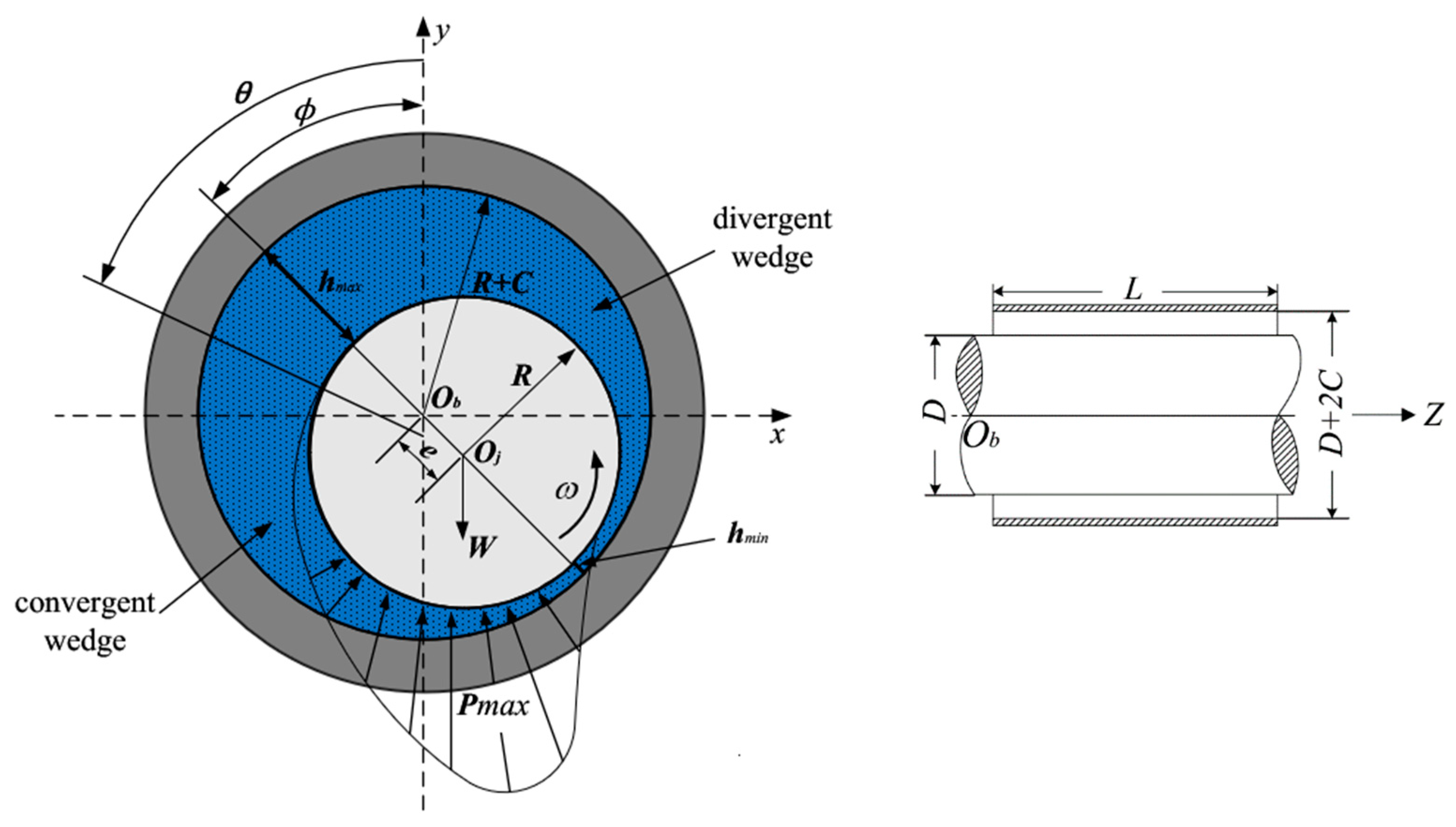
As shown in Figure 2, the rotation of the journal drives the lubrication oil in the radial clearance that forms the hydrodynamic pressure to support the load on the shaft. The oil film pressure distribution is dominated by the Reynolds equation; its nondimensional form is expressed as follows:
θ ( H 3 P θ ) + ( D L ) 2 λ ( H 3 P λ ) = P 0 H θ + 2 H t
where the dimensionless parameters are given as:
H = h / c = 1 x ¯ c o s ( θ ϕ ) y ¯ s i n ( θ ϕ ) ,   P = p / P 0 ( P 0 = 2 η ω R 2 / c 2 ) ,   θ = x / R ( 0 θ 2 π ) ,   λ = Z / L ( 0 λ 1 ) ,   x ¯ = x / c ,   y ¯ = y / c ,   τ = θ ˙ t = ω t .
where c is the bearing radial clearance, R is the bearing radius, D is the bearing diameter, L is bearing length and η is oil viscosity.
The hydrodynamic force can then be obtained by integrating p over the oil film:
F x = R L 0 1 θ 1 θ 2   p s i n θ d θ d λ ,   F y = R L 0 1 θ 1   θ 2 p c o s θ d θ d λ
With the hydrodynamic forces, the static equilibrium position where the hydrodynamic force is equal to the external load can be estimated by using the two-dimensional Newton–Raphson iterative algorithm. Then, the initial values of the eccentricity and attitude angle are corrected by the following equation:
| F x / F y | γ ,   ϕ = ϕ i n i t i a l a r c t g ( F x / F y ) ,   F = F x 2 + F y 2
Then, the dimensionless load capacity is:
F ¯ = ( c / R ) 2 / 2 η ω R L · F = 0 1 θ 1 θ 2   P s i n θ d θ d λ
The dimensionless friction force is obtained by:
F t = R L 0 1 θ 1 θ 2   ( h 2 p R θ + η ω R h ) d θ d λ , F ¯ t = ( c / R ) 2 / 2 η ω R L · F t = R C 0 1 θ 1 θ 2   ( H P θ + 1 H ) d θ d λ  
The friction coefficient f can be calculated by:
f = F ¯ t / F ¯
The dimensionless end leakage flow rates Q1 and Q2 are given by:
Q 1 = R L θ 1 θ 2 h 3 12 η p λ | λ = 0 d θ ,   Q 2 = R L θ 1 θ 2 h 3 12 η p λ | λ = 1 d θ
Q = | Q 1 | + | Q 2 |
Q ¯ = 3 L ω c R 3 Q = θ 1 θ 2 H 3 P λ | λ = 1 d θ
The static characteristics are important aspects of the lubrication performance of hydrodynamic bearings, and the consequence of wear on these parameters are discussed in Section 3.1.

2.2.1. Linear Oil Film Force Model

When the journal is disturbed by displacement or velocity, the reaction force of the fluid film changes correspondingly, which can be linearized if the perturbation is small. The equivalent linearized dynamic coefficients can be calculated by utilizing the perturbation algorithm [39]. The dimensionless perturbated Reynolds equation can be derived as follows:
θ H 3 P i θ + D L 2 λ H 3 P i λ = cos θ 3 sin θ H H θ H 3 P 0 θ θ sin θ θ P i = P x sin θ 3 cos θ H H θ H 3 P 0 θ θ cos θ θ P i = P y 2 sin θ P i = P x ˙ 2 cos θ P i = P y ˙
Integrating the solutions of Equation (25) in the oil film area, the dimensionless dynamic coefficients can be acquired.
K x x K y x } = 0 1 θ 1 θ 2 P x {   s i n θ c o s θ } d θ d λ ,   K x y K y y } = 0 1 θ 1 θ 2   P y {   s i n θ c o s θ } d θ d λ
C x x C y x } = 0 1 φ 1 φ 2   P x ˙ {   s i n θ c o s θ } R d θ d λ ,   C x y C y y } = 0 1 θ 1 θ 2   P y ˙ {   s i n θ c o s θ } R d θ d λ
[ K B ] = [ K x x   K x y K y x   K y y ] ,   [ C B ] = [ C x x   C x y C y x   C y y ]
Superposing these coefficients into the system matrices results in the characteristic equation of Equation (1) by using the state-space method:
[ 0                                                                                                                 I M 1 ( K s + K B )                       M 1 ( C s + C B + ω G )               ] = 0
The critical speeds and mode shapes can be estimated by working out the state matrix eigenvalues and corresponding eigenvectors. When the bearing geometry or working conditions change, the equivalent stiffness and damping coefficients can approximately denote the dynamic characteristics of the bearing, which is very critical for the stability analysis of the RB system.

2.2.2. Nonlinear Oil Film Force Model

To evaluate the nonlinear behavior of the rotor system, an appropriate nonlinear oil film force model must be applied. The existing nonlinear oil film force analytical models all have specific application ranges; for the irregular geometry of a worn bearing, the numerical integration solution is an accurate and appropriate choice.
After the computation of F x 0 and F y 0 at the static equilibrium position, the solution of displacement vectors x and y and velocity vectors x ˙ and y ˙ of the dynamic equation of the rotor system can be obtained due to the joint action of the nonlinear oil film force and unbalanced force. Precisely because of the existence of the nonlinear oil film force, the rotor trajectory becomes irregular. Note that all motion parameters are functions of time t:
F h x = F h x { e ,   ϕ ,   x ,   y ,     x ˙ ,   y ˙ ,   ω ,   t } ,   F h y = F h y { e ,   ϕ ,   x ,   y ,     x ˙ ,   y ˙ ,   ω ,   t }
The four variables e ,   ϕ ,   F h x   and F h y are estimated at each time step after building the pressure field corresponding to the position of the journal. Then, the oil film components F h x and F h y are iterated to the motion equation to obtain the response of the next time step. In this manner, the bearing conditions are correlated with the response of the rotor system.

2.3. Modeling of Worn Bearing

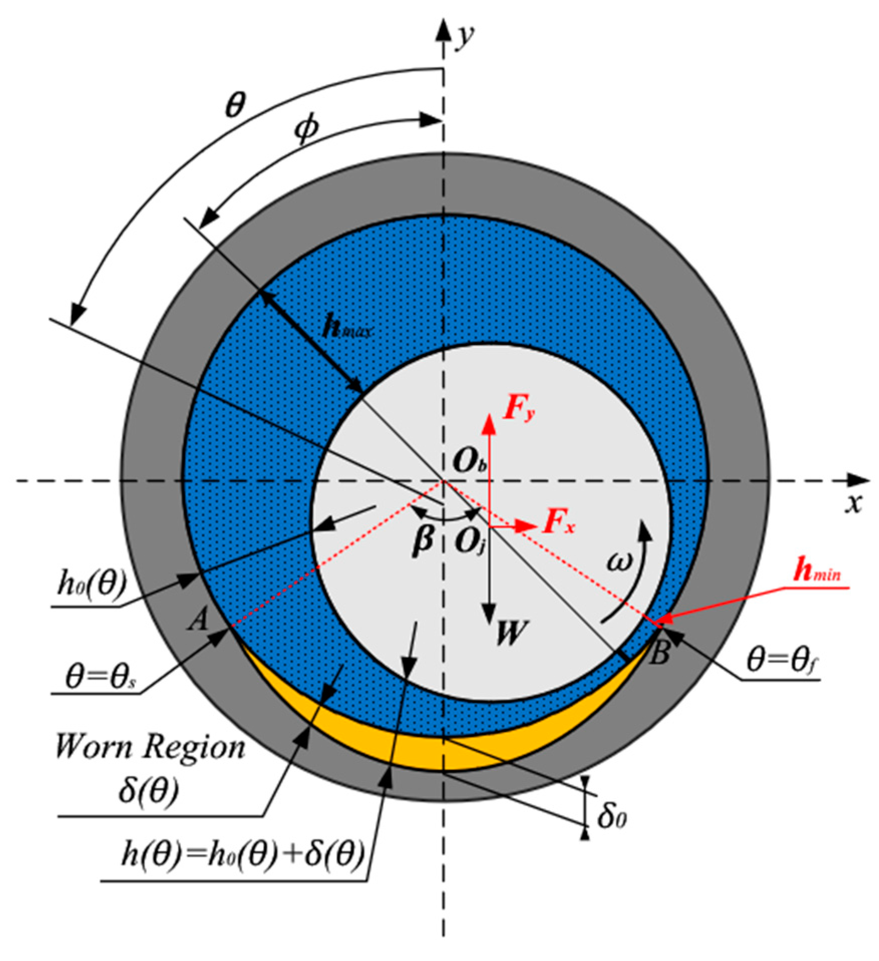
The occurrence of a wear fault results in a change in bearing clearance, which not only influences the bearing’s static characteristics but also affects the dynamic behavior of the rotor-bearing system. To evaluate the wear-induced fluid film thickness, the abrasive wear model proposed by Dufrane [2] is applied here. In this model, as pictured in Figure 3, as the shape of the worn bearing surface changes, an arc larger than the radius of the journal is superposed on the bottom of the bearing. The starting position θ s and ending position θ f depend on the maximum wear depth at the bottom.
According to Dufrane’s wear model, the wear shape of the bearing is expressed in Equation (25):
δ / c = δ 0 / c ( 1 + c o s θ )
where δ is the wear depth at the angle θ , δ 0 is the peak wear depth at the bottom of the bearing, c is the radial clearance, and θ is the angle from the y-axis.
The fluid film thickness of a worn hydrodynamic bearing is then expressed in Equation (26):
h ( θ ) = { h ,     0 θ θ s   ,   θ f θ 2 π h + δ , θ s < θ < θ f
The starting position θ s and ending position θ f can be estimated by substituting δ   = 0 into Equation (27):
c o s θ = δ 0 c 1 ,   θ s = c o s 1 ( δ 0 c 1 ) ,   θ f = 2 π 2 c o s 1 ( δ 0 c 1 )
Wear directly affects the oil film thickness distribution, especially at the bottom of the bearing surface, and the position of the minimum oil film thickness is also significantly changed. For a journal, with the consideration of its irregular geometry because of wear, combined with the calculation method of nonlinear oil film force, the effects of wear on the static and dynamic characteristics of the bearing and its vibration behavior can be accurately evaluated.

3. Simulation Results and Discussion

A wear fault results in a change in the fluid film shape and thus affects the pressure distribution, static equilibrium position, natural frequency and vibrational behavior of the rotor system. In this section, the effects of wear on the performance of the rotor system are numerically studied. Table 1 lists the simulation parameters, which were chosen according to a test rig that will be described in the next section. The vibration signatures were evaluated after calculating the unbalanced frequency response from the RB system model, and then the temporal domain responses were analyzed by both numerical simulations and experimental measurements. The simulated dynamic signals were compared with the experimental signals to verify the validity of the model. The specific steps of the proposed method are summarized as follows, and the flowchart is shown in Figure 4.

3.1. Algorithm Validation

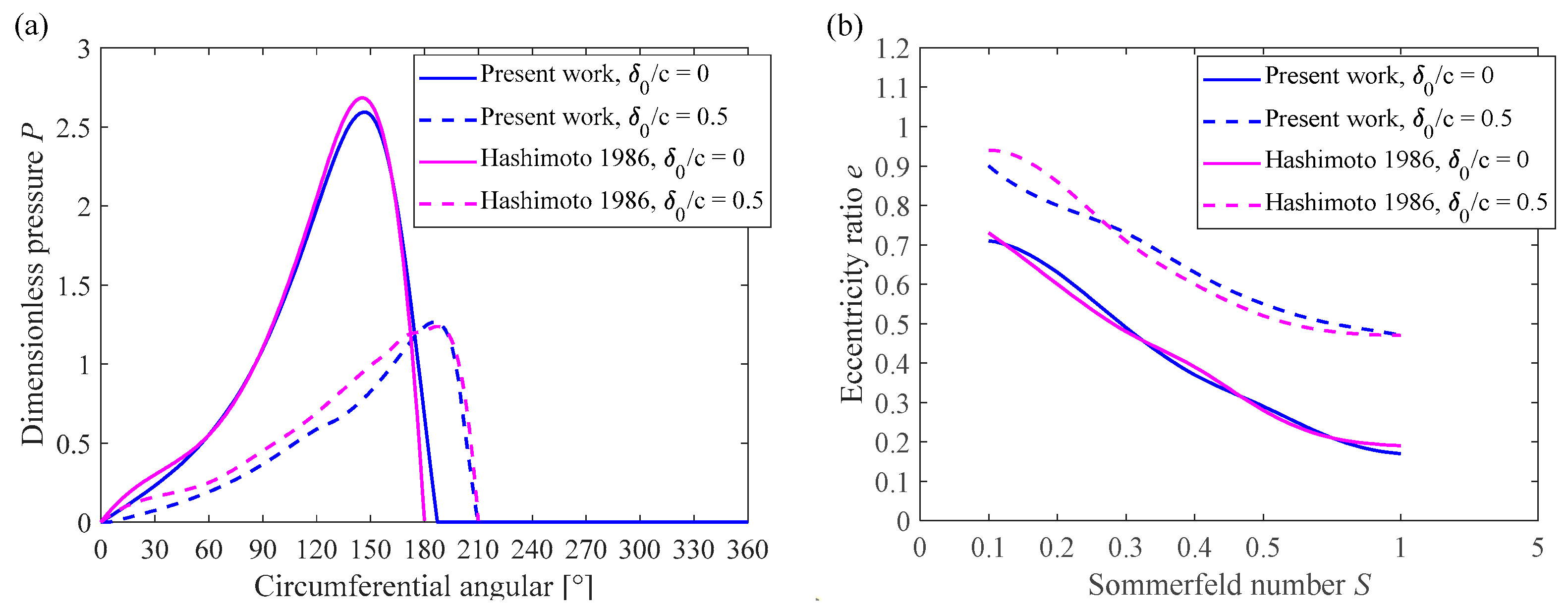
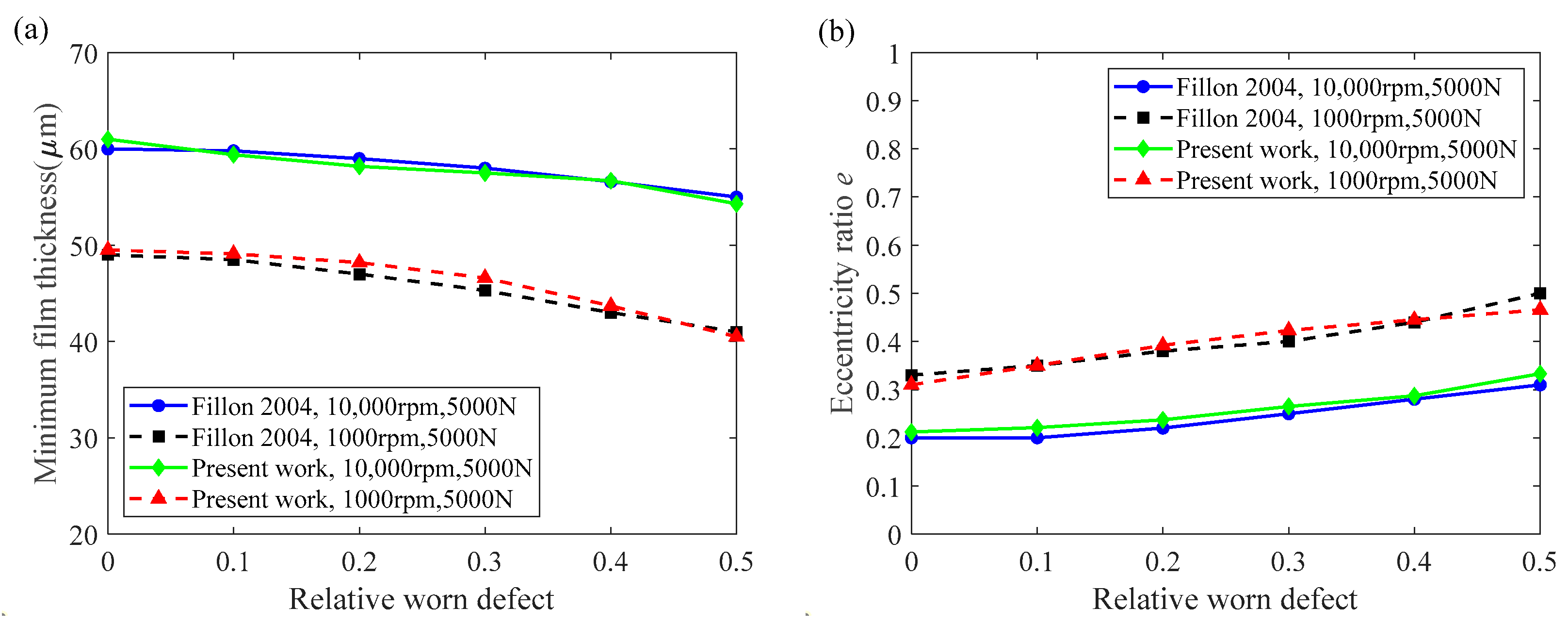
In this section, two diagrams are presented to compare the simulation results with those published in the literature. The pressure distribution and load capacity of the oil film (Sommerfield number) are compared with the experimental results of Hashimoto [3] in Figure 5, and then a comparison of the minimum film thickness and eccentricity ratio with Fillon and Bouyer’s [6] results is illustrated in Figure 6. The geometric and operating parameters of these two studies are listed together in Table 2. Figure 5 and Figure 6 depict a good agreement between the present wear model and the reference experimental and simulation results, which indicates that the proposed model and algorithm are able to calculate the performance of worn bearings, and the obtained simulation results are precise enough to be applied in the subsequent analysis.

3.2. Static Characteristics

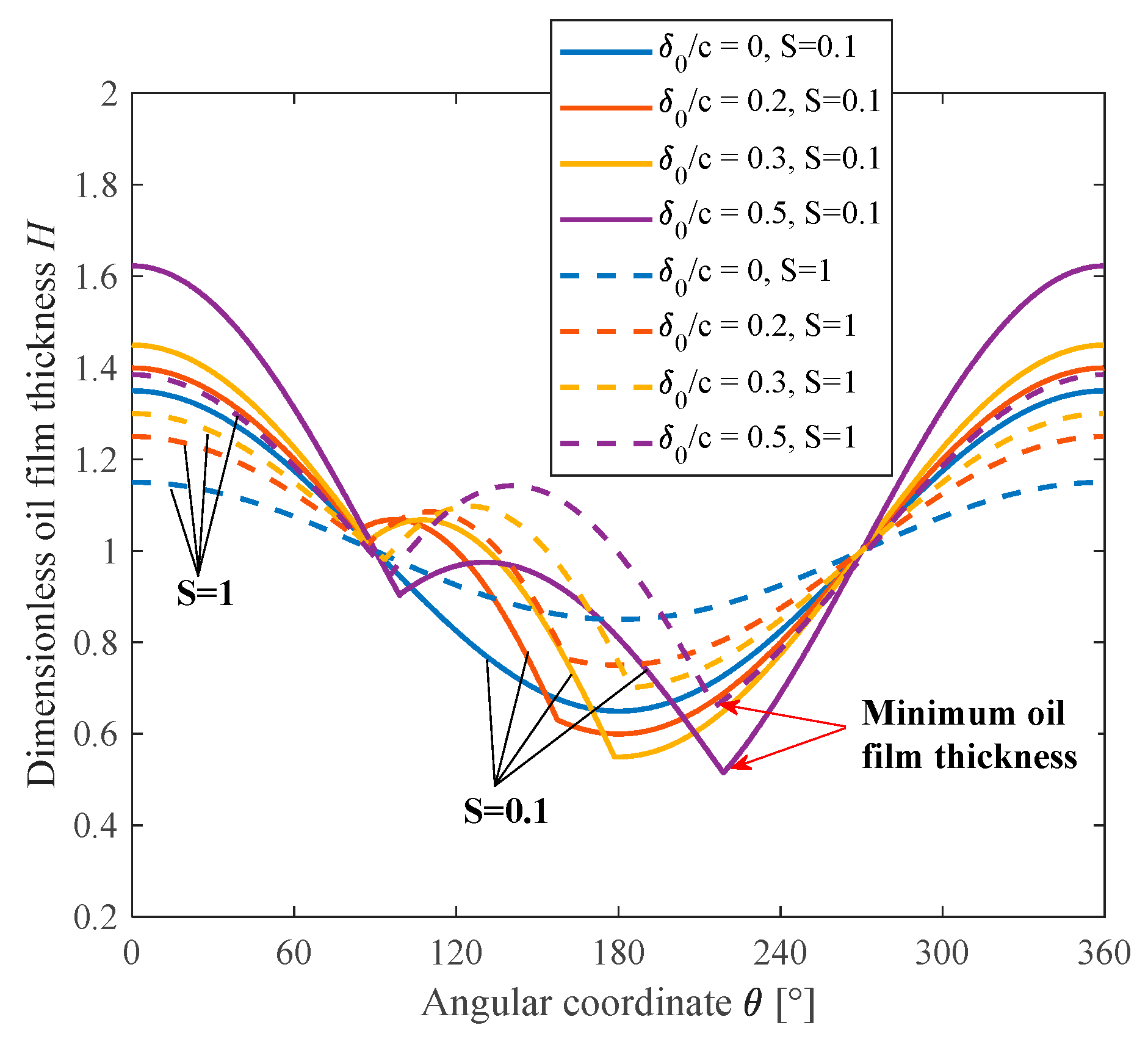
In this section, the Sommerfield number S represents the comprehensive operating condition of the hydrodynamic bearing. The static balanced position and the corresponding oil film thickness with different wear depths are then calculated. As described in Figure 7, the variation tendencies of the maximum and minimum oil film thicknesses are opposite due to wear. The former gradually increases while the latter decreases, which indicates that the journal spins at the equilibrium position close to the bearing under the same operating conditions. Moreover, the angle θ of the minimum film thickness increases with the wear depth at two different Sommerfield numbers. For the intact bearing, the oil film thickness exhibits a smooth shape, but for the worn bearing, two inflection points can be observed at the beginning and ending positions of the wear region. When entering the wear region, the oil film thickness abruptly increases, which results in a drop in the hydrodynamic pressure in this region.
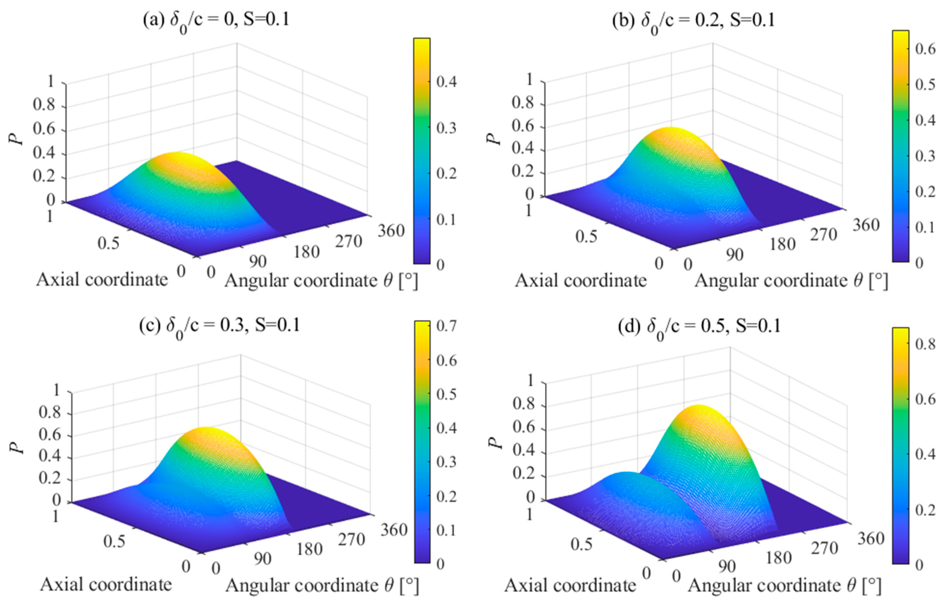
To illustrate the pressure drop induced by the wear, 3D pressure distributions with three cases of wear depth are given in Figure 8. As the wear depth increases, the pressure drop in the wear region becomes clearer, and two local pressure peaks appear around this region. When the wear fault reaches a serious degree, as illustrated in Figure 8d, a zero-pressure region even appears in the convergent wedge, where the load capability is totally lost. Moreover, the maximum hydrodynamic pressure increases gradually because the minimum fluid film thickness decreases after wear in the same working conditions.
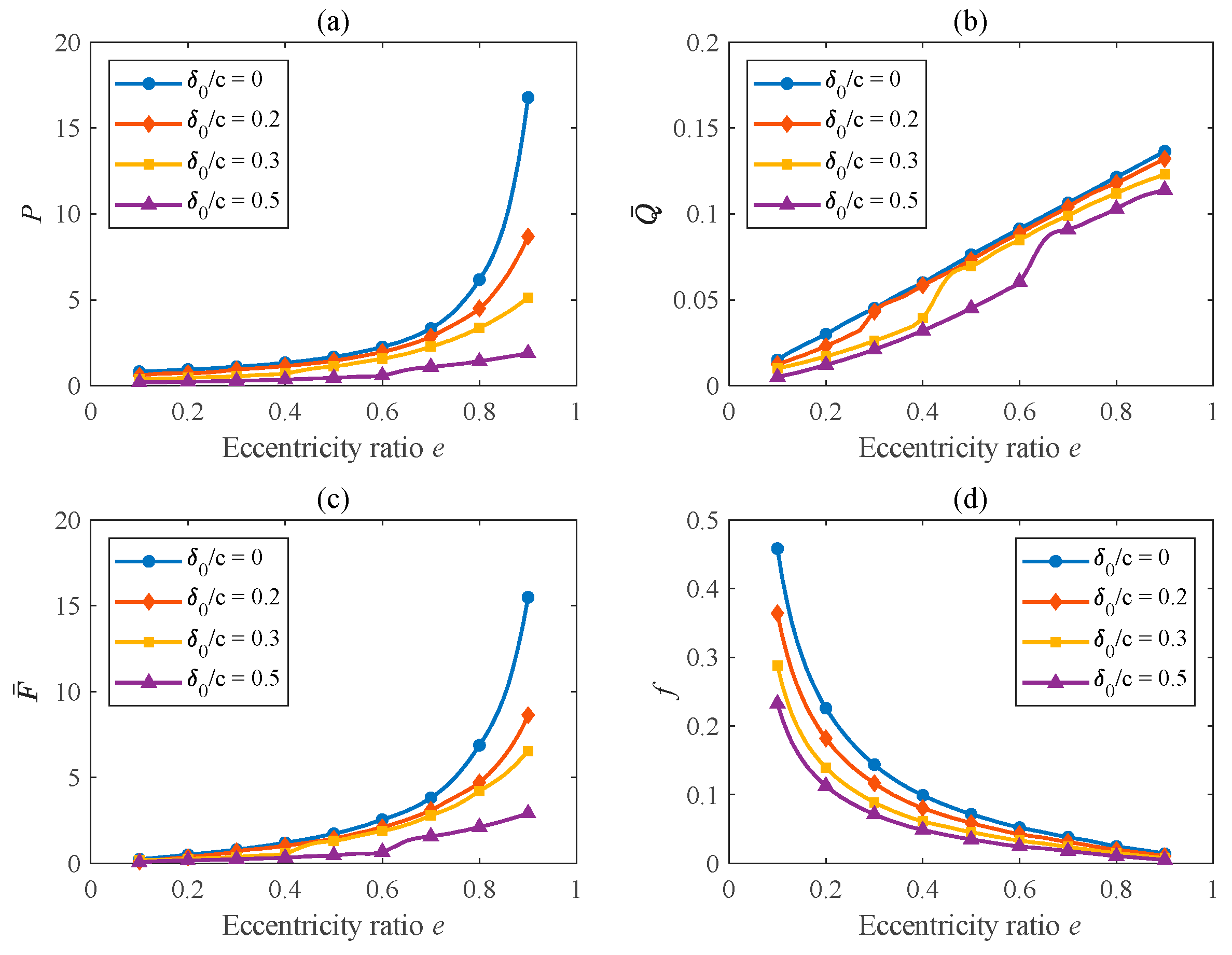
The variation in the static equilibrium due to different wear depths is illustrated in Figure 9. As the Sommerfeld number S increases from 0.01 to 1, the equilibrium position moves from the bottom to the center of the bearing. As the wear degree deepens, the journal will spin at the position with a large eccentricity ratio and a small attitude angle under the same S, indicating that the wear resulted in the loss of the load capability of the hydrodynamic bearing. The influence of wear degree and the increasing eccentricity ratio on the maximum oil film pressure, end leakage flow rate, load capacity and friction coefficient of the hydrodynamic bearing are depicted in Figure 10. All static characteristics are decreased because of greater wear, especially at a high eccentricity ratio. This is because the journal is closer to the wear area when the eccentricity is large, where the difference in the oil film thickness distribution becomes more obvious.

3.3. Stiffness and Damping Coefficients

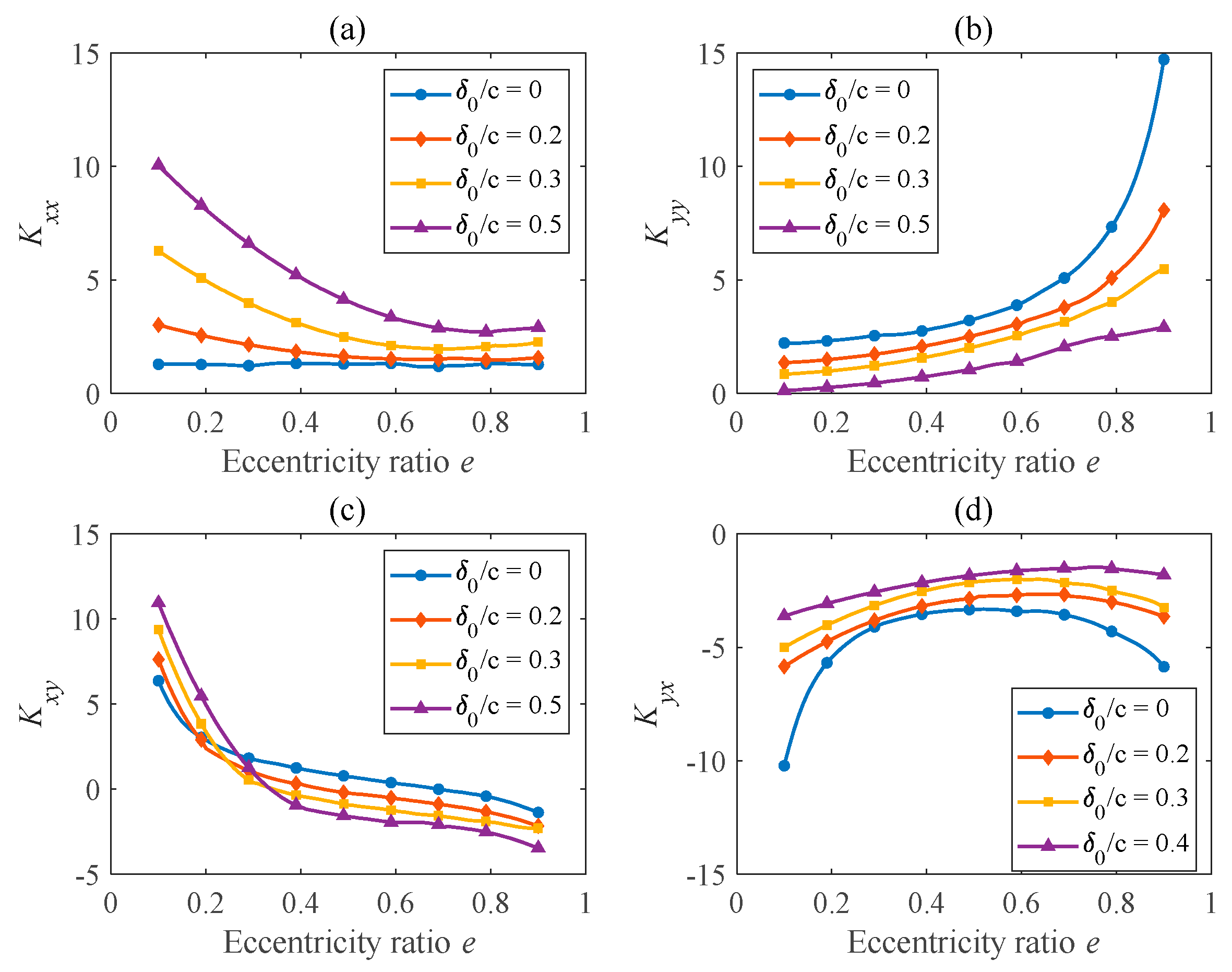
The stiffness and damping coefficients of the hydrodynamic bearing with different wear depths are calculated via the perturbation method at the corresponding static equilibrium positions. As shown in Figure 11a, as the wear depth increases, the direct stiffness coefficient Kxx increases, especially for equilibrium positions with a small eccentricity ratio. An opposite trend is observed for the relationship between the wear depth and direct stiffness coefficient Kyy, as shown in Figure 11b. Compared with the intact bearing, Kxx increases while Kyy decreases. The effects of wear on Kxy and Kyx are more complicated, and they play an important role in the stability of the rotor system. As shown in Figure 11c, a deeper wear depth leads to a large slope of the curve for the cross-coupling stiffness coefficient Kxy. The transition point from positive values to negative values appears at smaller e. As displayed in Figure 11d, the curve for the cross-coupling stiffness coefficient Kyx becomes flat with a larger wear depth. Figure 12 shows the effects of wear on the four damping coefficients of the hydrodynamic bearing. It can be observed that as the wear depth increases, all damping coefficients increase, especially at a smaller eccentricity ratio.

3.4. Critical Speeds and Mode Shapes

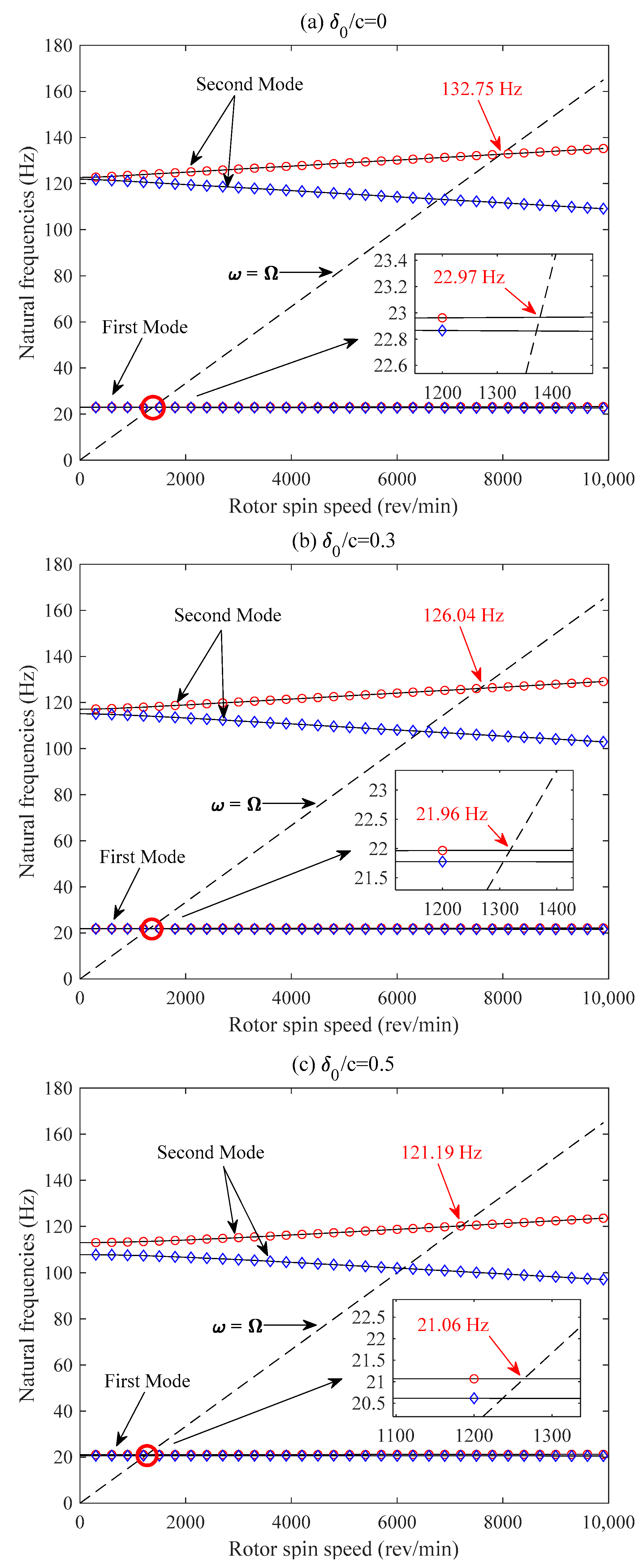
With the calculation of the dynamic characteristics of the bearing, critical speeds and the corresponding mode shapes can be estimated via the eigenanalysis of Equation (1). In this section, the effects of the wear depth on critical speeds are studied through Campbell diagrams. Two modes are considered within the frequency range of interest. It can be observed in Figure 13 that due to gyroscopic effects, natural frequencies separate into two lines: forward (circle marker) and backward (diamond marker) whirling of the rotor for each mode. Due to the existence of the unbalanced force, the direction of rotor movement is consistent with the shaft spin direction, so the first- and second-order critical speeds can be obtained from the intersection points between the black dotted line ( ω = Ω ) and natural frequencies for forward whirling.
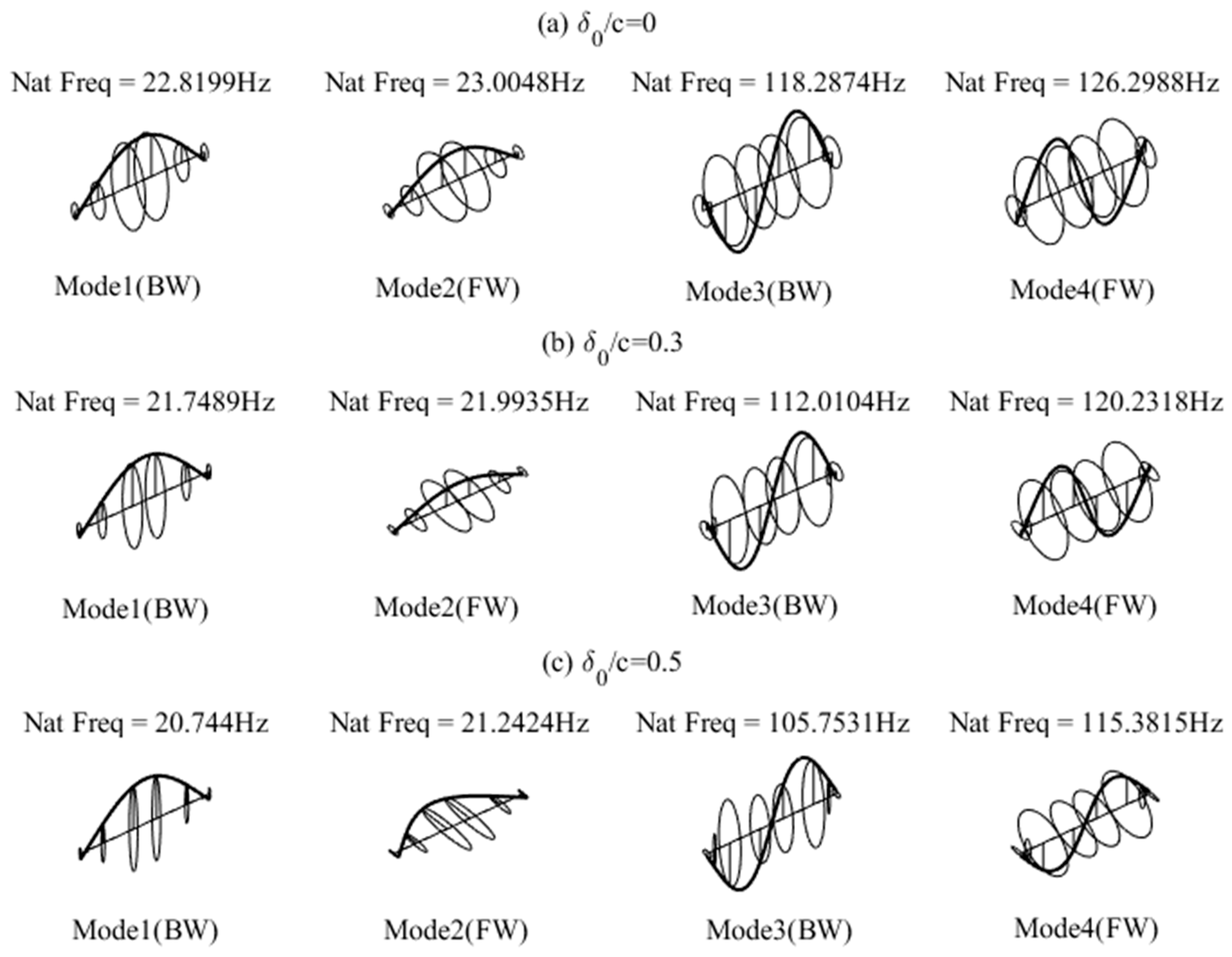
As shown in Figure 13, for the intact bearing, the first- and second-order critical speeds are 22.97 Hz and 132.75 Hz, respectively. For the wear parameter δ 0 / c = 0.3, the critical speeds fall to approximately 21.96 Hz and 126.04 Hz, decreasing by 4.39% and 5.05%, respectively. As the wear depth increases further to δ 0 / c = 0.5, the critical speeds drop to approximately 21.06 Hz and 121.19 Hz, decreasing by 8.32% and 8.71%, respectively. It is deduced that the wear fault could lead to a drop in the critical speeds of the system because the fault-induced bearing clearance increase attenuates the constraint provided by the bearing to the rotor. In addition, system critical speeds of higher orders decline more compared to lower orders. The first four rotor mode shapes at a rotational speed of 3000 rev/min are demonstrated in Figure 14, where the mode shapes become more irregular and closer to an ellipse, which is due to the increase in the wear-induced anisotropy of bearing stiffness.

3.5. Vibrational Behavior of the Rotor-Bearing System

Using the nonlinear oil film force model, the vibrational behavior of the RB system with different wear depths, i.e., δ 0 / c = 0, δ 0 / c = 0.3 and δ 0 / c = 0.5, were simulated. In the finite element model, which is demonstrated in Figure 1b, the wear fault is assumed to exist at bearing 2, while bearing 1 is assumed to be intact. Displacements of the worn bearing were used to study the system’s vibrational behavior. According to the simulation results in the aforementioned section, the first-order critical speed of the rotor system is located within the range from 20 Hz to 30 Hz, where the vibration behavior changes dramatically. In order to have an insight into this phenomenon, calculation interval refinement was conducted for rotational speeds within this range.
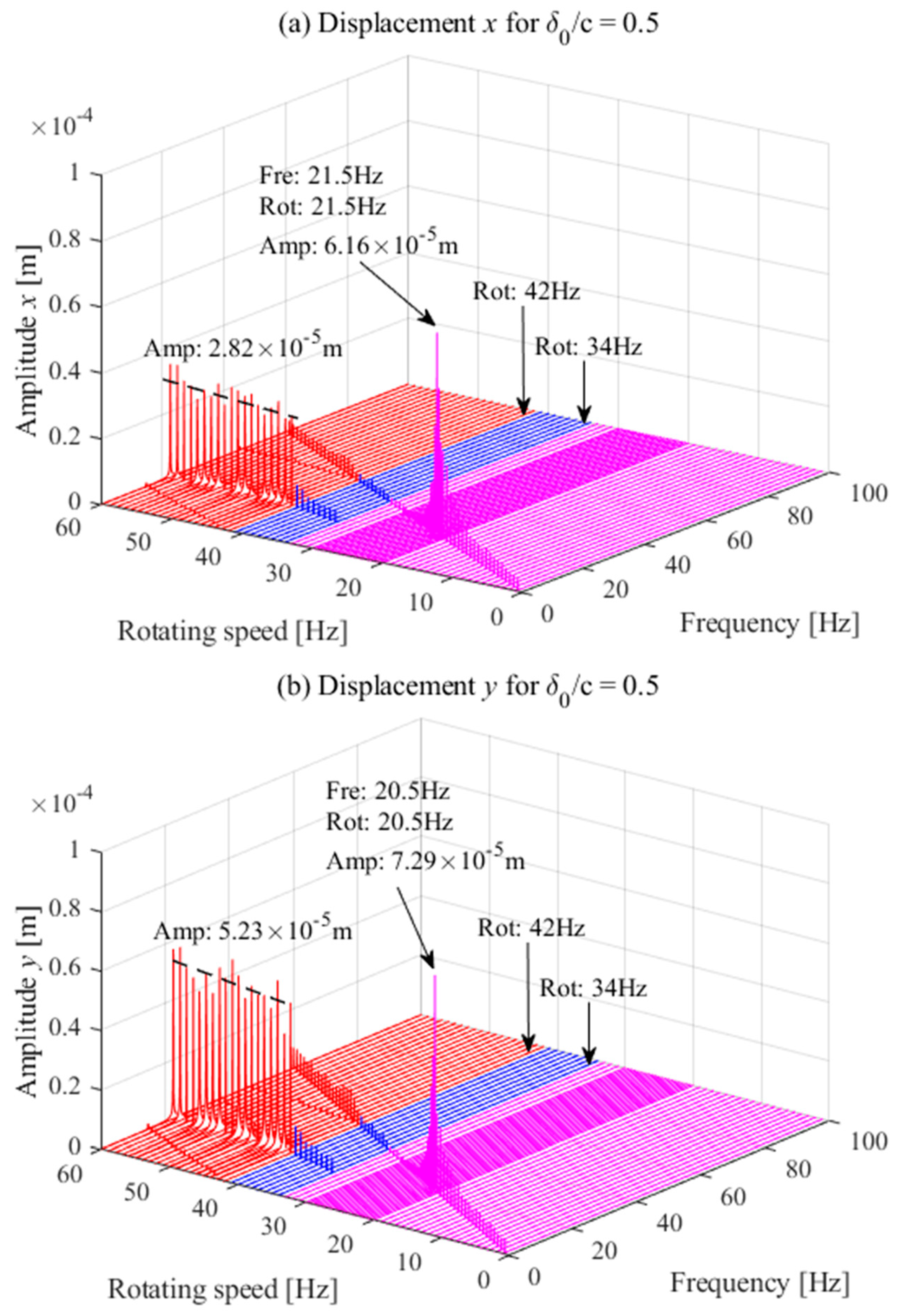
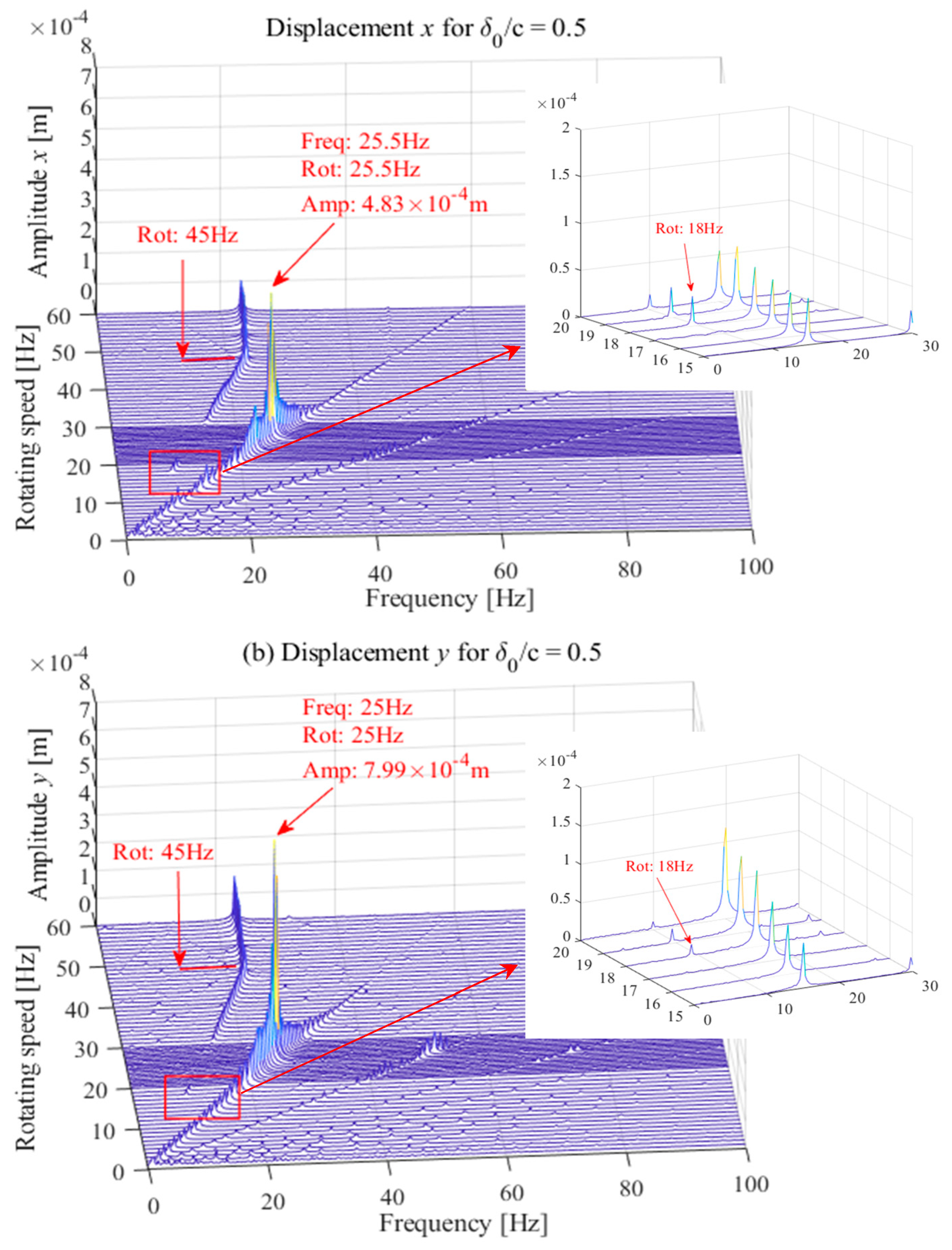
Figure 15, Figure 16 and Figure 17 show waterfall diagrams of the vibrational behavior of the RB system. Since the excitation sources in the system involve the unbalanced force, oil film force and gravity, a synchronous component (1.0 × ) and subsynchronous component (0.5 × ) mainly appear in the diagram. For the intact bearing, as illustrated in Figure 15, the critical speed is approximately 23 Hz, around which the vibration energy is mainly distributed on the synchronous component. At a rotational speed of 16 Hz, oil whirl occurs with a relatively low amplitude until reaching a rotational speed of 46 Hz, when oil whip occurs. At such a rotational speed, which is equal to approximately twice the first-order critical speed, there is a sharp increase in the amplitude and the vibration energy transfers from the synchronous component to the subsynchronous component. The vibration characteristics are comparable in both the x- and y-directions, except that the vibration amplitude of displacement y is slightly greater than that in the x-direction. For the worn bearing with a wear parameter of δ 0 / c = 0.3, as described in Figure 16, the critical speed drops to 22 Hz and 21.5 Hz, respectively, in the x- and y-directions, which is in accordance with the analysis based on the linear model. The difference is due to wear located at the bottom of the bearing, which increases the anisotropy of the bearing stiffness. According to the linear analysis in Section 3.2, wear has a greater impact on the stiffness coefficient in the y-direction than in the x-direction. The onset rotational speed of oil whirl increases to approximately 28 Hz, which is above the first-order system critical speed. The reason for the improvement in system stability is that the journal would spin at the equilibrium position with a larger eccentricity ratio under the same operating conditions. However, the onset speed of oil whip decreases to 44 Hz due to the drop in the first-order critical speed. The resonance and oil whip amplitudes increase compared to those of the intact bearing, and obviously, the growth rate of displacement y is greater than that of displacement x. For the wear parameter δ 0 / c = 0.5, as can be observed in Figure 17, the critical speed of the system drops further to 21.5 Hz for displacement x and 20.5 Hz for displacement y when the resonance amplitude becomes larger. The onset rotational speeds of oil whirl and oil whip are approximately 28 Hz and 44 Hz, respectively. The vibration amplitude during oil whirl and oil whip becomes much larger in both the x- and y-directions.
The vibration amplitudes of resonance and the amplitude in different directions are compared in Figure 18; as previously mentioned, the vibration amplitudes of displacements x and y are about the same when the bearing is intact. The equation Δ = | x y | is used to measure the difference between the amplitude values in the x- and y-directions. As the wear depth grows, both the resonance and oil whip amplitudes increase, and the value of Δ becomes larger and larger, which indicates that the difference between x- and y-direction amplitudes can be used as an indicator of the occurrence of a wear fault. The resonance values of Δ are 0.19 × 10⁻⁵ m, 0.65 × 10⁻⁵ m and 1.13 × 10⁻⁵ m at different wear degrees, and the oil whip values of Δ are 0.24 × 10⁻⁵ m, 1.19 × 10⁻⁵ m and 2.41 × 10⁻⁵ m, respectively. It can be observed that the oil whip value of Δ is more sensitive to wear and is a more effective parameter to identify wear.
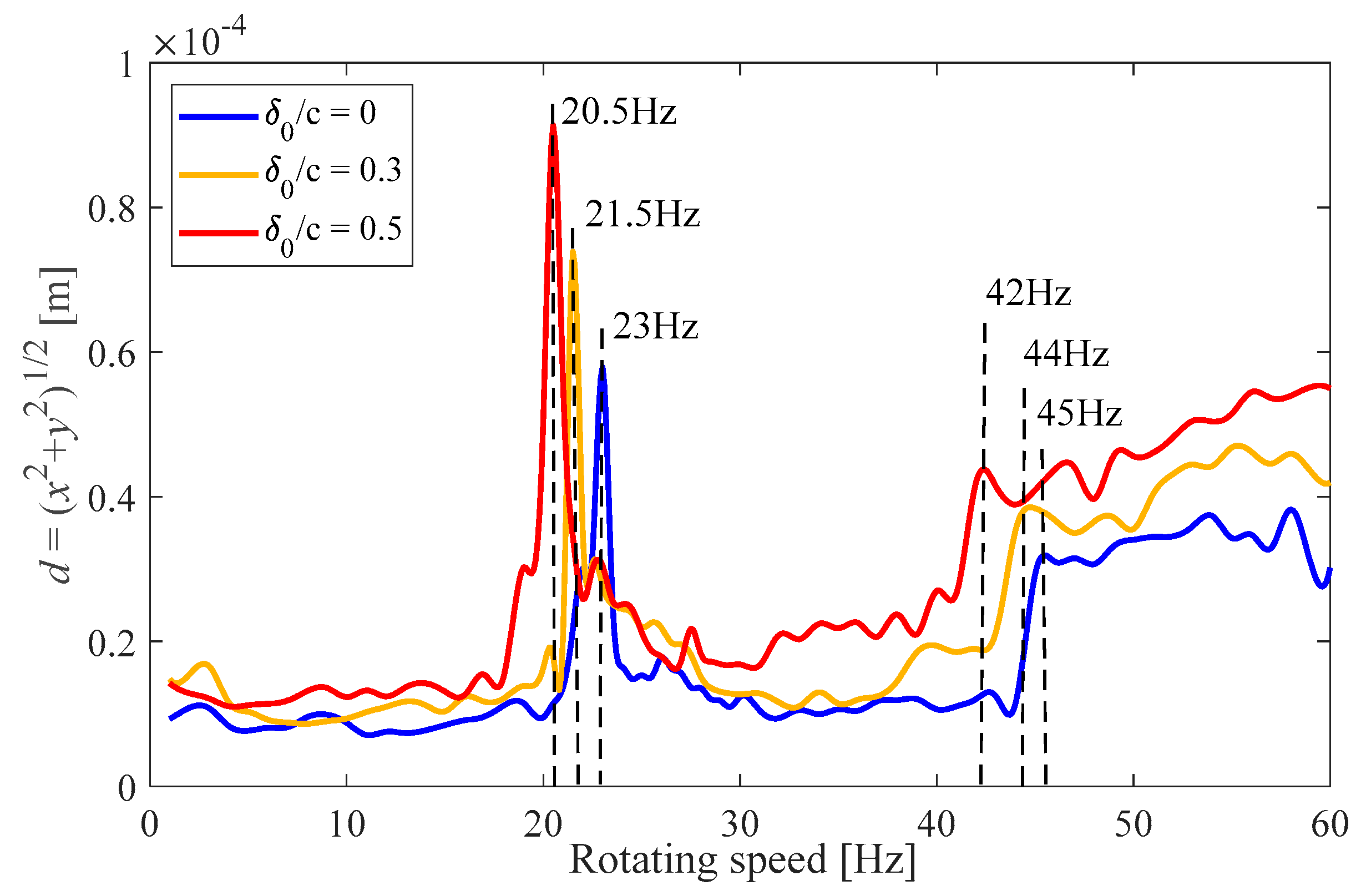
Figure 19 demonstrates the progression of deflection in the hydrodynamic bearings with increasing rotational speed. Different wear depths are considered for each curve. The effect of bearing wear on rotor vibration energy is clearly described, and the vibration energy increases to some extent, especially in the resonance and oil whip zone. The features analyzed in waterfall plots can also be expressed here; that is, the rotating speeds that cause resonance and oil whip to occur are constantly decreased by wear.
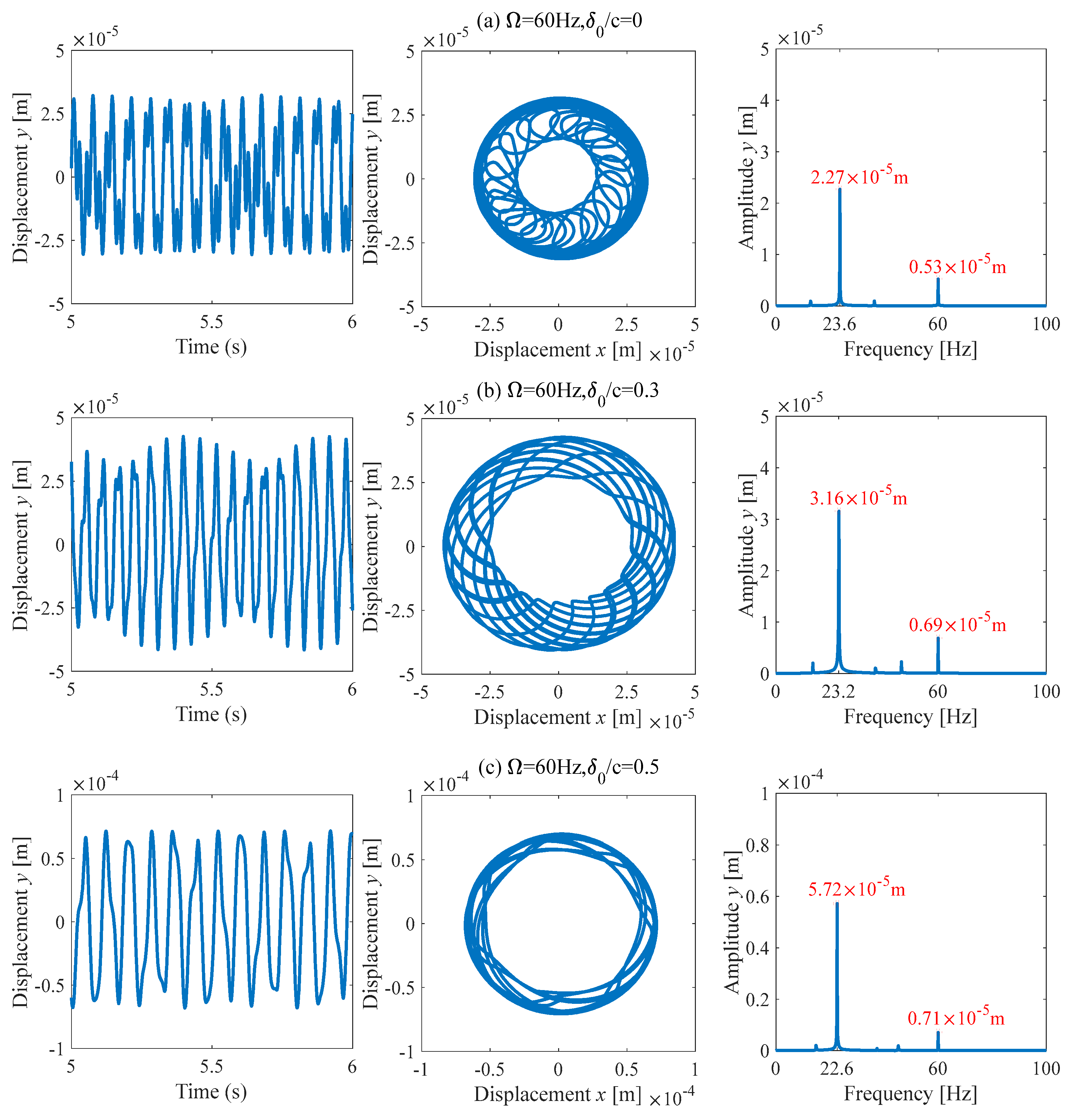
To further study the vibrational behavior of the rotor system, the temporal signal, shaft orbit and corresponding frequency spectrum at a specific rotational speed of 60 Hz are provided in Figure 20. The wear fault affects the distribution of the vibration energy. As the wear depth increases, more vibration energy transfers to the subsynchronous component at the rotational speed of 60 Hz, at which time the shaft orbit looks like a squirrel cage. The rotor is the stage of oil whip at the rotational speed of 60 Hz, and oil whip dominates the vibration behavior at this time. As the wear depth increases, the amplitude of the subsynchronous component increases significantly, and the energy of the synchronous component is suppressed. The difference in the amplitude between subsynchronous and synchronous components becomes larger due to the appearance of the wear fault.

4. Experimental Validation

4.1. Test Rig Description

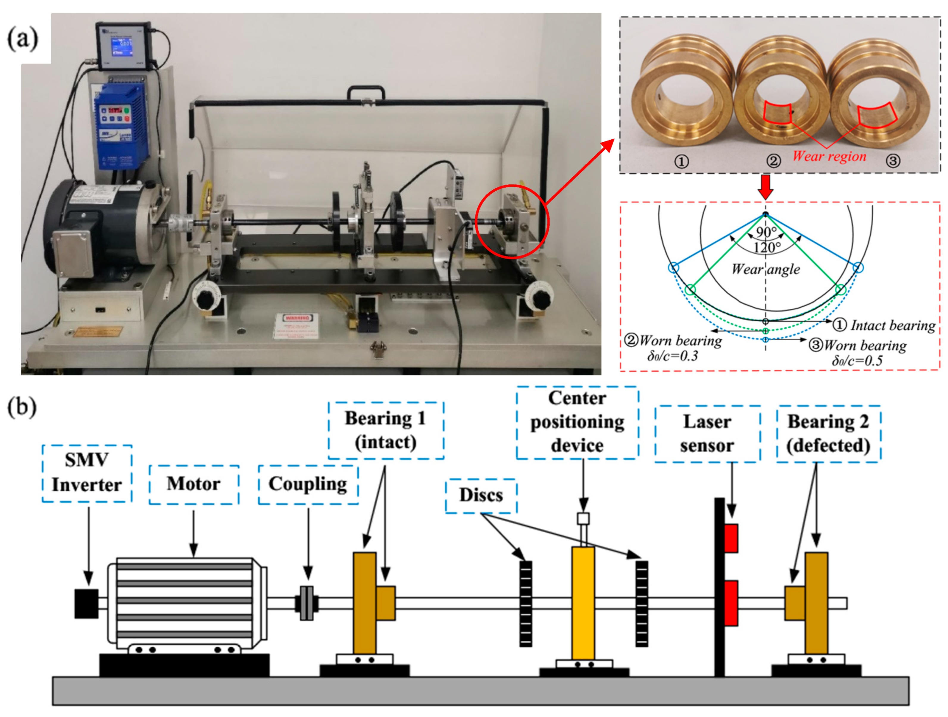
The vibration behavior of the rotor system was experimentally studied to verify the results of the numerical analysis. Figure 21 shows a photograph and schematic of the MFS-RDS rotor-bearing test rig. An AC motor controlled by an SMV inverter drives a shaft that is supported on a pair of hydrodynamic bearings. Two rigid disks on which unbalanced mass can be exerted are mounted on the shaft. A center positioning device is used to balance the gravity of the rotor system. A pair of OD2-X50 laser displacement sensors are perpendicularly installed to measure the horizontal and vertical displacement responses of the journal. More specific geometric and operational parameters of the test rig are listed in Table 1.
The left bearing was left intact, and the right bearing was replaced by a set of hydrodynamic bearings. As pictured in Figure 21a, two hydrodynamic bearings were adopted here to carry out the comparative experiment. One bearing was intact, and the others were machined to introduce wear faults with different depths, namely, δ 0 / c = 0.3 and δ 0 / c = 0.5. The rotor was steadily operated within the rotational speed range of 1–60 Hz, and the corresponding shaft displacements were then collected using a 6250 Hz sampling frequency.

4.2. Experimental Results and Discussion

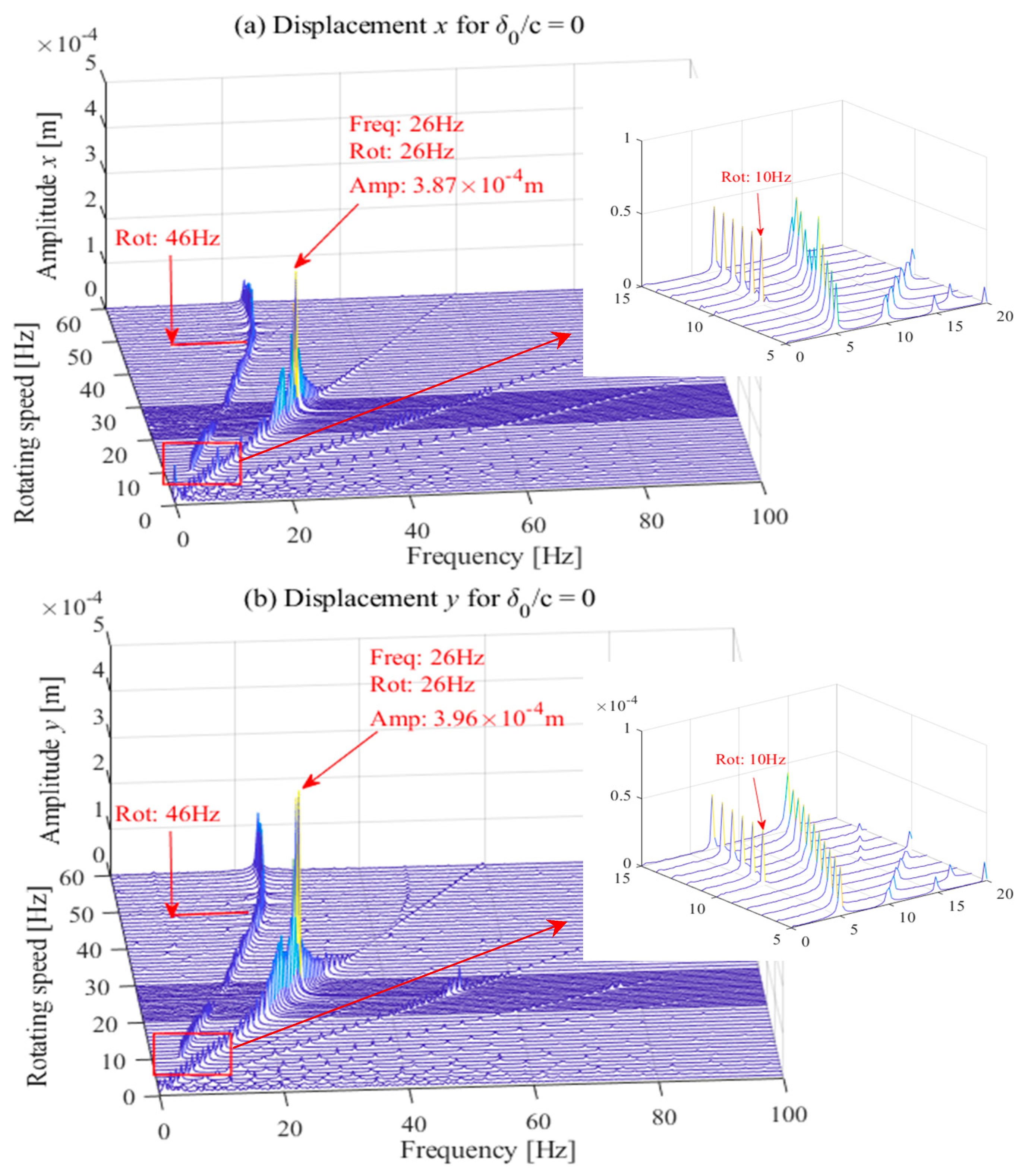
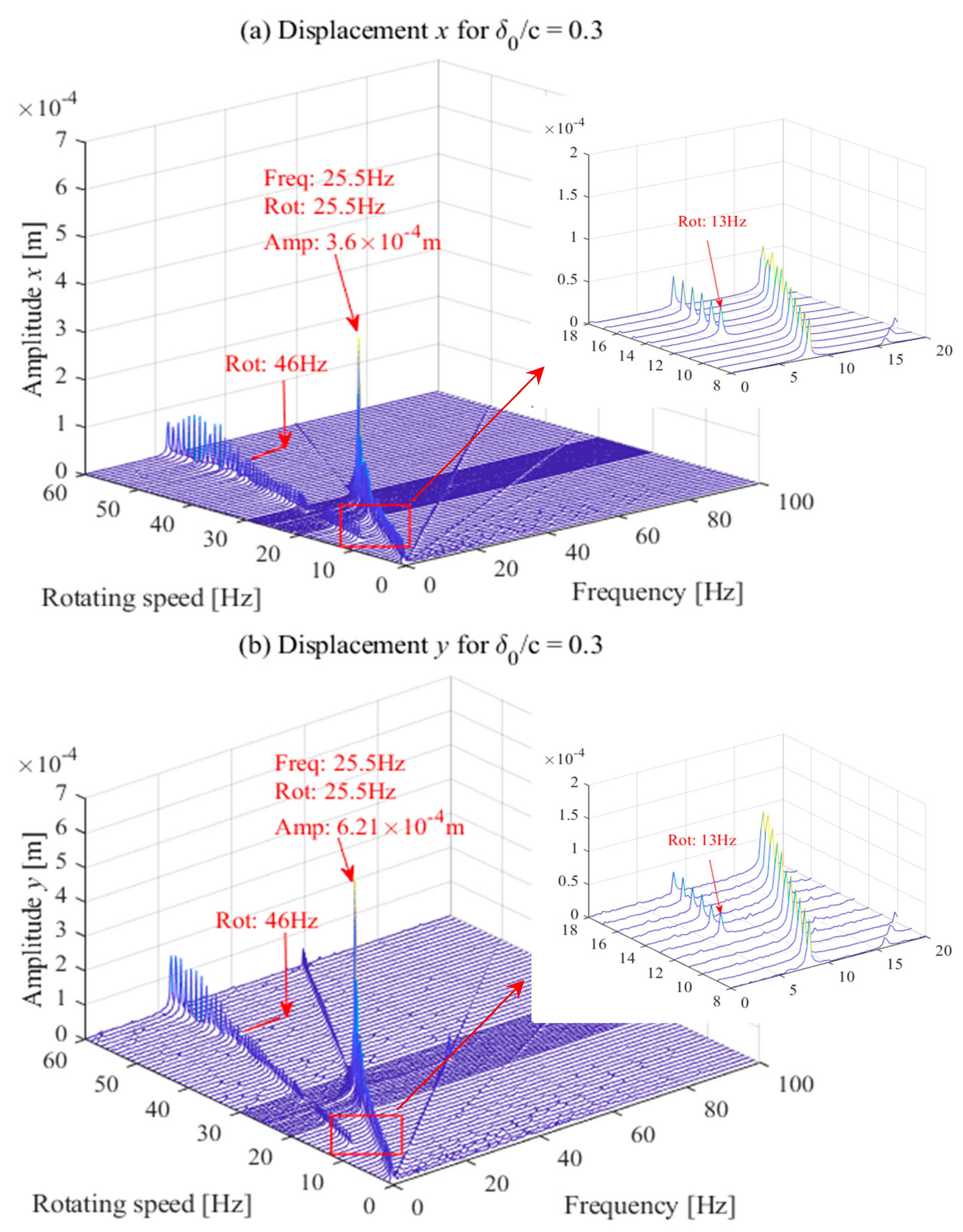
Waterfall diagrams of the vibrational behavior of the rotor system with different wear depths are given in Figure 22, Figure 23 and Figure 24. In order to clearly observe the vibration near the critical speed, tests were carried out every 0.5 Hz within the speed range of 20–30 Hz. Compared to the simulation observations shown in Figure 15, Figure 16 and Figure 17, more vibration components can be observed in the experimental results. Besides the synchronous component (1.0 × ) and subsynchronous component (0.5 × ), additional harmonic components are excited due to the residual misalignment, coupling effect, etc. From the energy point of view, however, the vibration energy is still mainly distributed on the synchronous and subsynchronous components.
For the intact bearing, as depicted in Figure 22, the first critical speed is approximately 26 Hz, where the vibration amplitude reaches a peak value, and most of the vibration energy is distributed at the 1.0 × component. The oil whirl phenomenon occurs at approximately 10 Hz, which is far less than the critical speed. When increasing the rotational speed to about 46 Hz, which is twice the critical speed, the amplitude of the subsynchronous component suddenly increases, indicating the appearance of the oil whip phenomenon. As the rotational speed further increases, oil whip gradually weakens. For the worn bearing with the wear parameter δ 0 / c = 0.3 , as shown in Figure 23, the system critical speed drops to approximately 25.5 Hz, where the vibration amplitude of the synchronous component appears to become larger compared with the intact bearing. The onset speed of the oil whirl phenomenon increases to approximately 13 Hz. Until the rotational speed reaches about 46 Hz, i.e., twice the first critical speed, the oil whip phenomenon continues to occur and lasts for a wide speed range. Compared with the intact bearing, the amplitude of the rotational frequency becomes larger. For the wear parameter δ 0 / c = 0.5 , as shown in Figure 24, the system critical speed further declines to approximately 25.5 Hz and 25 Hz, where the amplitude of the synchronous component further increases. The oil whirl phenomenon occurs at a speed of 18 Hz. When the rotating speed of the rotor increases to approximately 45 Hz, the oil whip phenomenon occurs with a larger vibration amplitude compared to that of intact and slightly worn bearings.
The vibration amplitudes of experimental signals in the x- and y-directions are compared in Figure 25. The resonance values of Δ are 0.09 × 10⁻⁴ m, 2.61 × 10⁻⁴ m and 3.16 × 10⁻⁴ m, and the oil whip values of Δ are 0.36 × 10⁻⁴ m, 0.68 × 10⁻⁴ m and 0.8 × 10⁻⁴ m, respectively, at different wear degrees. There is the same trend as the simulation signals, in which the difference in the resonance and oil whip amplitudes between the x- and y-directions become larger and larger with the increase in wear depth.
Figure 26 illustrates the temporal signal, shaft orbit and corresponding frequency spectrum of the rotor vibration measured at the specific rotational speed of 20 Hz. Both synchronous and subsynchronous components exist for all three cases; as the wear depth increases, the proportion of the subsynchronous component becomes lower compared with the proportion of the synchronous component. This is consistent with the analysis of the waterfall diagram, in which the energy of the subsynchronous component declines gradually with wear. At a lower rotational speed before oil whip, the synchronous frequency is the dominant component of the vibration behavior of the rotor, which means that the operational stability of the rotor is improved due to the appearance of wear.
It can be seen that the experimental results agree well with the observations from the simulation results. Bearing wear could lead to a reduction in critical speeds. Interestingly, the trend of variation in the x-direction and y-direction is the same, while the variation magnitude is different. The stability performance could also be affected by the wear fault. As the wear depth increases, the occurrence of the oil whirl phenomenon is postponed to a higher rotational speed, but the oil whip phenomenon with a larger amplitude is more likely to be excited, so the subsynchronous component of oil whip is sustained within a wider speed range. Such findings suggest that wear will improve rotor stability at lower rotational speeds and reduce rotor stability at higher rotational speeds.

5. Conclusions

This paper presents an investigation of the lubrication performance and vibrational behavior of a rotor system supported on worn hydrodynamic bearings in order to lay a theoretical basis for the wear detection of hydrodynamic bearings. Dufrane’s abrasive model was introduced to describe the wear-induced change in the oil film thickness. The oil film force was evaluated by linear and nonlinear models in the developed FEM of the rotor-bearing system. The effects of wear on bearing characteristics and vibration signatures were numerically and experimentally studied. The main findings of this work are as follows:
(1) As the wear depth increases, the minimum oil film thickness decreases, but the maximum oil film thickness increases. Under the same operating conditions, the journal will spin at a different static equilibrium position with a larger eccentricity and a smaller attitude angle, indicating that the wear resulted in the loss of the load capability of the hydrodynamic bearing. Wear also leads to changes in the static and dynamic characteristics of the hydrodynamic bearing, among which the latter have an important impact on the vibrational behavior of the rotor system.
(2) The wear fault would lead to a drop in critical speeds because the fault-induced bearing clearance increase attenuates the constraint provided by the bearing to the rotor. Higher orders of system critical speeds decline more compared to lower orders. Meanwhile, the resonance amplitude of the synchronous component constantly increases as the wear depth increases, and it is proven that vibration in the y-direction is more sensitive to wear compared to that in the x-direction, regardless of the resonance amplitude and the value of the natural frequency. The difference in vibration characteristics in different directions is an effective signature for wear fault diagnosis.
(3) The stability threshold of the rotor-bearing system would also be affected by the wear fault. As the wear depth increases, the occurrence of oil whirl phenomenon is postponed to a higher rotational speed, because the journal will spin at the equilibrium position with a larger eccentricity ratio under the same operating conditions. Due to the drop in the first-order critical speed, however, the oil whip phenomenon with a larger amplitude is more likely to be excited and sustained in a wider speed range. Such findings indicate that wear will improve rotor stability at lower rotational speeds and reduce rotor stability at higher rotational speeds. Similarly, the oil whip amplitude in the y-direction increases more sharply than in the x-direction.
In summary, the present work shows that wear has a clear influence on the lubrication performance of hydrodynamic bearings and the vibration behavior of the rotor system, and the vibration signatures of the rotor system are found to be effective indicators for the occurrence of wear faults. In this context, the results obtained in this work can be applied to improve the fault diagnosis and condition monitoring of hydrodynamic bearings.

Author Contributions

Conceptualization, H.Z. and Z.S.; methodology, Y.C. and H.Z.; software, Y.C.; validation, Y.C.; formal analysis, S.X.; investigation, X.L. and S.X.; resources, Z.S. and H.Z.; data curation, F.G.; writing—original draft preparation, Y.C.; writing—review and editing, Y.C. and H.Z.; supervision, H.Z. and F.G.; funding acquisition, H.Z. and X.L. All authors have read and agreed to the published version of the manuscript.

Funding

This research was funded by [National Natural Science Foundation of China], grant number [52175085]; [Natural Science Foundation of Hebei Province], grant number [E2022202185] and [Foundation Project of the National Key Laboratory of Diesel Engine Supercharging], grant number [6142212220302].

Data Availability Statement

Not applicable.

Conflicts of Interest

The authors declare no conflict of interest.

Abbreviations

NotationMatrices
cbearing radial clearance (m)[M]global mass matrix
Rbearing radius (m)[K]global stiffness matrix
Dbearing diameter (m)[C]global damping matrix
Lbearing length (m)[G]global gyroscopic matrix
hoil film thickness (m)[MS]element mass matrix of shaft
ƞoil viscosity (Pa.s)[GS]element gyroscopic matrix of shaft
p oil film pressure (Pa)[KS]element stiffness matrix of shaft
x, ydisplacement in x- and y-directions (m)[CS]element damping matrix of shaft
x ˙ ,   y ˙ velocity in x- and y-directions (m/s)[Gd]element gyroscopic matrix of disc
Eelastic modulus (GPa)[Md]element mass matrix of disc
Isecond moment of area (m4)[KB]bearing stiffness matrix
Aarea of the axial cross-section (m2)[CB]bearing damping matrix
llength of the shaft element (m){Fu}unbalanced force vector
m d mass of disk (kg){Fh}nonlinear oil film force vector
I d moment of inertia of disk (kg.m2){Wi}gravity vector
I p polar moment of inertia of the disk (kg.m2)Greek symbols
F h x   ,   F h y nonlinear oil film force (N) ω 1 ,   ω 2 first and second natural frequencies (rad/s)
φ initial phase angle (rad) ξ 1 ,   ξ 2 first and second modal damping ratios
Dimensionless parameters α ,   β Rayleigh parameters
Pdimensionless oil film pressure δ wear depth at any angle (m)
F ¯ dimensionless load capacity θ rotation angle from y-axis (rad)
F ¯ t dimensionless friction force ϕ attitude angle (rad)
Q ¯ dimensionless end leakage ω angular speed (rad/s)
Kijdimensionless stiffness coefficientsρ material density (kg/m3)
Cijdimensionless stiffness coefficients θ x ,   θ y angles around the x-axis and y-axis (rad)
q ¯ dimensionless displacement vector θ s ,   θ f starting and end position of wear region (rad)
τ dimensionless time H dimensionless oil film thickness
eeccentricity ratio λ dimensionless bearing length

References

  1. Mokhtar, M.O.A.; Howarth, R.B.; Davies, P.B. Wear characteristics of plain hydrodynamic journal bearings during repeated starting and stopping. ASLE Trans. 1977, 20, 191–194. [Google Scholar] [CrossRef]
  2. Dufrane, K.F.; Kannel, J.W.; McCloskey, T.H. Wear of steam turbine journal bearings at low operating speeds. J. Lubr. Tech. 1983, 105, 313–317. [Google Scholar] [CrossRef]
  3. Hashimoto, H.; Wada, S.; Nojima, K. Performance characteristics of worn journal bearings in both laminar and turbulent regimes, Part I: Steady-state characteristics. ASLE Trans. 1986, 29, 565–571. [Google Scholar] [CrossRef]
  4. Kumar, A.; Mishra, S. Stability of a rigid rotor in turbulent hydrodynamic worn journal bearings. Wear 1996, 193, 25–30. [Google Scholar] [CrossRef]
  5. Kumar, A.; Mishra, S. Steady state analysis of noncircular worn journal bearings in nonlaminar lubrication regimes. Tribol. Int. 1996, 29, 493–498. [Google Scholar] [CrossRef]
  6. Fillon, M.; Bouyer, J. Thermohydrodynamic analysis of a worn plain journal bearing. Tribol. Int. 2004, 37, 129–136. [Google Scholar] [CrossRef]
  7. Lee, D.; Sun, K.H.; Kim, B.; Kang, D. Thermal behavior of a worn tilting pad journal bearing: Thermohydrodynamic analysis and pad temperature measurement. Tribol. Trans. 2018, 61, 1074–1083. [Google Scholar] [CrossRef]
  8. Awasthi, R.K.; Sharma, S.C.; Jain, S.C. Performance of worn non-recessed hole-entry hybrid journal bearings. Tribol. Int. 2007, 40, 717–734. [Google Scholar] [CrossRef]
  9. Nikolakopoulos, P.G.; Papadopoulos, C.A. A study of friction in worn misaligned journal bearings under severe hydrodynamic lubrication. Tribol. Int. 2008, 41, 461–472. [Google Scholar] [CrossRef]
  10. Sander, D.E.; Allmaier, H. Starting and stopping behavior of worn journal bearings. Tribol. Int. 2018, 127, 478–488. [Google Scholar] [CrossRef]
  11. Jia, H.; Li, J.; Wang, J.; Xiao, K.; Han, Y. A lubricated wear model for determining wear surface geometry on journal-bearing surfaces. Surf. Topogr. Metrol. Prop. 2020, 8, 035002. [Google Scholar] [CrossRef]
  12. König, F.; Chaib, A.O.; Jacobs, G.; Sous, C. A multiscale-approach for wear prediction in journal bearing systems—From wearing-in towards steady-state wear. Wear 2019, 426, 1203–1211. [Google Scholar] [CrossRef]
  13. Liu, G.; Li, M. Lubrication Characteristics of Water-Lubricated Rubber Bearings with Partial Wear. J. Fluids Eng. 2020, 142, 021209. [Google Scholar] [CrossRef]
  14. Winkler, A.; Bartz, M.; Wartzack, S. Numerical Wear Modeling in the Mixed and Boundary Lubrication Regime. Lubricants 2022, 10, 334. [Google Scholar] [CrossRef]
  15. Xiang, G.; Han, Y.; Wang, J.; Ni, X. Coupling transient mixed lubrication and wear for journal bearing modeling. Tribol. Int. 2019, 138, 1–15. [Google Scholar] [CrossRef]
  16. Xiang, G.; Wang, C.; Wang, Y.J.; Han, Y.F.; Wang, J.X.; Lv, J.L. Dynamic Mixed Lubrication Investigation of Water-Lubricated Bearing with Unbalanced Rotor during Start-Up. Tribol. Trans. 2021, 64, 764–776. [Google Scholar] [CrossRef]
  17. Papadopoulos, C.A.; Nikolakopoulos, P.G.; Gounaris, G.D. Identification of clearances and stability analysis for a rotor-journal bearing system. Mech. Mach. Theory 2008, 43, 411–426. [Google Scholar] [CrossRef]
  18. Chasalevris, A.C.; Nikolakopoulos, P.G.; Papadopoulos, C.A. Dynamic effect of bearing wear on rotor-bearing system response. J. Vib. Acoust. 2013, 135, 011008. [Google Scholar] [CrossRef]
  19. Chasalevris, A.; Dohnal, F.; Chatzisavvas, I. Experimental detection of additional harmonics due to wear in journal bearings using excitation from a magnetic bearing. Tribol. Int. 2014, 71, 158–167. [Google Scholar] [CrossRef]
  20. Machado, T.H.; Cavalca, K.L. Modeling of hydrodynamic bearing wear in rotor-bearing systems. Mech. Res. Commun. 2015, 69, 15–23. [Google Scholar] [CrossRef]
  21. Machado, T.H.; Cavalca, K.L. Investigation on an experimental approach to evaluate a wear model for hydrodynamic cylindrical bearings. Appl. Math. Model. 2016, 40, 9546–9564. [Google Scholar] [CrossRef]
  22. Mendes, R.U.; Machado, T.H.; Cavalca, K.L. Experimental wear parameters identification in hydrodynamic bearings via model based methodology. Wear 2017, 372, 116–129. [Google Scholar] [CrossRef]
  23. Machado, T.H.; Alves, D.S.; Cavalca, K.L. Investigation about journal bearing wear effect on rotating system dynamic response in time domain. Tribol. Int. 2019, 129, 124–136. [Google Scholar] [CrossRef]
  24. Alves, D.S.; Fieux, G.; Machado, T.H.; Keogh, P.S.; Cavalca, K.L. A parametric model to identify hydrodynamic bearing wear at a single rotating speed. Tribol. Int. 2021, 153, 106640. [Google Scholar] [CrossRef]
  25. Wang, H.; Liu, Z.; Zou, L.; Yang, J. Influence of both friction and wear on the vibration of marine water lubricated rubber bearing. Wear 2017, 376, 920–930. [Google Scholar] [CrossRef]
  26. Visnadi, L.B.; De Castro, H.F. Influence of bearing clearance and oil temperature uncertainties on the stability threshold of cylindrical journal bearings. Mech. Mach. Theory 2019, 134, 57–73. [Google Scholar] [CrossRef]
  27. Dyk, Š.; Rendl, J.; Byrtus, M.; Smolík, L. Dynamic coefficients and stability analysis of finite-length journal bearings considering approximate analytical solutions of the Reynolds equation. Tribol. Int. 2019, 130, 229–244. [Google Scholar] [CrossRef]
  28. Zhang, H.; Ma, J.; Li, X.; Xiao, S.; Gu, F.; Ball, A.D. Fluid-asperity interaction induced random vibration of hydrodynamic journal bearings towards early fault diagnosis of abrasive wear. Tribol. Int. 2021, 160, 107028. [Google Scholar] [CrossRef]
  29. Ma, J.; Fu, C.; Zheng, Z.; Lu, K.; Yang, Y. The Effects of Interval Uncertainties on Dynamic Characteristics of a Rotor System Supported by Oil-Film Bearings. Lubricants 2022, 10, 354. [Google Scholar] [CrossRef]
  30. Yan, X.; Xu, X.; Sheng, C.; Yuan, C.; Li, Z. Intelligent wear mode identification system for marine diesel engines based on multi-level belief rule base methodology. Meas. Sci. Technol. 2017, 29, 015110. [Google Scholar] [CrossRef]
  31. Nissilä, J.; Laurila, J. Diagnosing simultaneous faults using the local regularity of vibration signals. Meas. Sci. Technol. 2019, 30, 045102. [Google Scholar] [CrossRef] [Green Version]
  32. De Castro, H.F.; Cavalca, K.L.; Nordmann, R. Whirl and whip instabilities in rotor-bearing system considering a nonlinear force model. J. Sound Vib. 2008, 317, 273–293. [Google Scholar] [CrossRef]
  33. Safizadeh, M.S.; Golmohammadi, A. Prediction of oil whirl initiation in journal bearings using multi-sensors data fusion. Measurement 2020, 151, 107241. [Google Scholar] [CrossRef]
  34. Ma, H.; Li, H.; Zhao, X.; Niu, H.; Wen, B. Effects of eccentric phase difference between two discs on oil-film instability in a rotor–bearing system. Mech. Syst. Signal Process. 2013, 41, 526–545. [Google Scholar] [CrossRef]
  35. Ma, H.; Wang, X.; Niu, H.; Wen, B. Oil-film instability simulation in an overhung rotor system with flexible coupling misalignment. Arch. Appl. Mech. 2015, 85, 893–907. [Google Scholar] [CrossRef]
  36. Machado, T.H.; Alves, D.S.; Cavalca, K.L. Discussion about nonlinear boundaries for hydrodynamic forces in journal bearing. Nonlinear Dynam. 2018, 92, 2005–2022. [Google Scholar] [CrossRef]
  37. Nelson, H.D.; McVaugh, J.M. The dynamics of rotor-bearing system using finite elements. J. Eng. Ind. 1976, 98, 593–600. [Google Scholar] [CrossRef]
  38. Bathe, K.; Wilson, E. Numerical Methods in Finite Element Analysis; Prentice-Hall Inc.: Hoboken, NJ, USA, 1976. [Google Scholar]
  39. Ebrat, O.; Mourelatos, Z.P.; Vlahopoulos, N.; Vaidyanathan, K. Calculation of journal bearing dynamic characteristics including journal misalignment and bearing structural deformation. Tribol. Trans. 2004, 47, 94–102. [Google Scholar] [CrossRef]
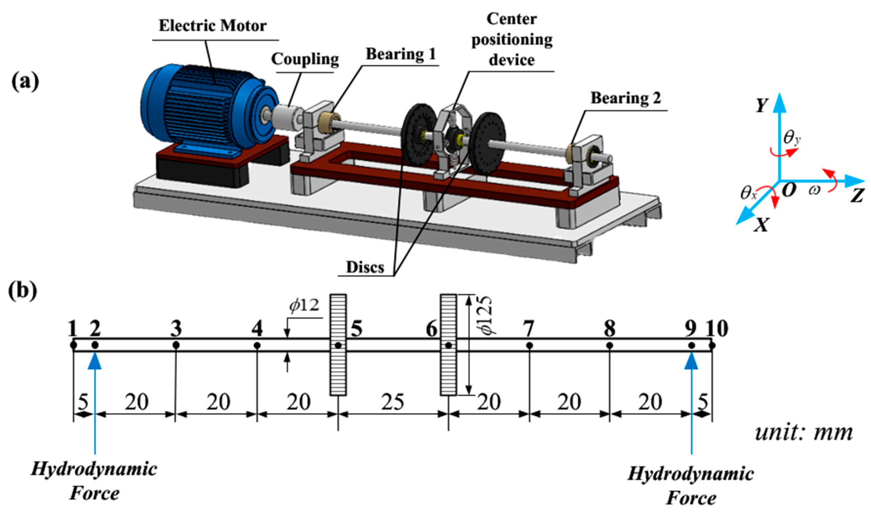
Figure 1. Rotor-bearing system: (a) physical model and (b) FEM.
Lubricants 11 00107 g001
Figure 2. Hydrodynamic bearing scheme and coordinate reference system.
Lubricants 11 00107 g002
Figure 3. Schematic diagram of a worn hydrodynamic bearing.
Lubricants 11 00107 g003
Figure 4. Flow diagram of the computational scheme.
Lubricants 11 00107 g004
Figure 5. Model validation for eccentric ratio e = 0.6 with Ref. [3]: (a) pressure distribution and (b) load capacity.
Lubricants 11 00107 g005
Figure 6. Validation of effects of relative worn defect with Ref. [6] (a) minimum film thickness and (b) eccentricity ratio e.
Lubricants 11 00107 g006
Figure 7. Oil film thickness for different wear degrees and Sommerfeld numbers.
Lubricants 11 00107 g007
Figure 8. Oil film pressure distribution.
Lubricants 11 00107 g008
Figure 9. Static equilibrium position of the hydrodynamic bearing with different wear depths.
Lubricants 11 00107 g009
Figure 10. Static characteristics of the hydrodynamic bearing with different wear depths: (a) dimensionless oil film pressure, (b) dimensionless end leakage flow ratio, (c) dimensionless load capacity and (d) friction coefficient.
Lubricants 11 00107 g010
Figure 11. Effects of wear on dimensionless stiffness coefficients: (a) Kxx, (b) Kyy, (c) Kxy and (d) Kyx.
Lubricants 11 00107 g011
Figure 12. Effects of wear on dimensionless damping coefficients: (a) Cxx, (b) Cyy and (c) Cxy and Cyx.
Lubricants 11 00107 g012
Figure 13. Campbell diagram of rotor-bearing system.
Lubricants 11 00107 g013
Figure 14. Mode shapes of system at 3000 rev/min.
Lubricants 11 00107 g014
Figure 15. Waterfall diagrams of simulation results with δ 0 / c = 0.
Lubricants 11 00107 g015
Figure 16. Waterfall diagrams of simulation results with δ 0 / c = 0.3.
Lubricants 11 00107 g016
Figure 17. Waterfall diagrams of simulation results with δ 0 / c = 0.5.
Lubricants 11 00107 g017
Figure 18. Comparison of vibration amplitudes in x-direction and y-direction with different wear depths.
Lubricants 11 00107 g018
Figure 19. Deflection of the rotor with different wear depths.
Lubricants 11 00107 g019
Figure 20. Simulation results of temporal signal, shaft orbit and frequency spectrum at 60 Hz.
Lubricants 11 00107 g020
Figure 21. Rotor-bearing test rig: (a) photograph and (b) schematic.
Lubricants 11 00107 g021
Figure 22. Waterfall diagrams of experimental results with δ 0 / c = 0.
Lubricants 11 00107 g022
Figure 23. Waterfall diagrams of experimental results with δ 0 / c = 0.3.
Lubricants 11 00107 g023
Figure 24. Waterfall diagrams of experimental results with δ 0 / c = 0.5.
Lubricants 11 00107 g024
Figure 25. Comparison of vibration amplitudes in x-direction and y-direction with different wear depths.
Lubricants 11 00107 g025
Figure 26. Experimental results of temporal signal, shaft orbit and frequency spectrum at 20 Hz.
Lubricants 11 00107 g026
Table 1. Simulation parameters of rotor-bearing system.
Bearing ParameterSpecificationRotor ParameterSpecification
Bearing length L (mm)20Shaft radius R1 (mm)10
Bearing diameter D (mm)20Shaft length l (mm)850
Radial clearance c (μm)100Disk radius R2 (mm)125
Maximum wear depth δ 0 (μm)20, 30, 50Disk thickness h2 (m)10
Viscosity η (Pa.s)0.0135Density ρ (kg/m^3)7850
Load W (N)100Elastic modulus E (GPa)211
Sommerfeld number S0.01~1Unbalanced moment me (kg.m)2 × 10⁻⁵
Table 2. Bearing parameters of published literature.
ParameterHashimoto [3]Fillon and Bouyer [6]
Bearing diameter (mm)70100
Bearing length (mm)70100
Radial clearance (μm)28775
Viscosity (Pa.s)14 × 10−30.03
Rotational speed (rpm)6151000 and 10,000
Load (N) 5000
Maximum wear depth (μm)142
Relative worn defect0.50~0.5
Disclaimer/Publisher’s Note: The statements, opinions and data contained in all publications are solely those of the individual author(s) and contributor(s) and not of MDPI and/or the editor(s). MDPI and/or the editor(s) disclaim responsibility for any injury to people or property resulting from any ideas, methods, instructions or products referred to in the content.