Article

Investigation on Surface Integrity in Hard Turning of AISI 4140 Steel with SPPP-AlTiSiN Coated Carbide Insert under Nano-MQL

1
Department of Production Engineering, Veer Surendra Sai University of Technology, Burla 768018, Odisha, India
2
Department of Applied Physics and Electronics, Umeå University, 90187 Umeå, Sweden
3
Department of Mechanical Engineering, Ganapati Institute of Engineering and Technology, Cuttack 754200, Odisha, India
4
Department of Mechanical Engineering, DIT University, Dehradun 248009, Uttarakhand, India
5
Department of Aeronautical Engineering, Sivas University of Science and Technology, Sivas 58000, Turkey
6
Department of Mechanical Engineering, KL University, Vijayawada 522302, Andhra Pradesh, India
*
Author to whom correspondence should be addressed.
Lubricants 2023, 11(2), 49; https://doi.org/10.3390/lubricants11020049
Submission received: 2 December 2022 / Revised: 18 January 2023 / Accepted: 28 January 2023 / Published: 30 January 2023
(This article belongs to the Special Issue Advances in Sustainable Machining)

Abstract

:
The machined surface integrity in the turning of hardened steels is adversely influenced by heat generation and friction which requires pacification of the temperature by the effective cooling-lubrication approach and cutting tool performance. The present research analyzes the surface integrity of hardened AISI 4140 steel during turning with recently developed scalable pulsed power plasma SPPP-AlTiSiN coated carbide tool under nanofluid-assisted minimum quantity lubrication (MQL). Zinc oxide nanoparticles and environmentally friendly radiator coolant are mixed to prepare the nano cutting fluid. This analysis addresses the various aspects of surface integrity concerning surface morphology, machined surface hardness, residual stress and white layer development, and machined surface finish under varying cutting parameters (depth of cut, speed, feed, nose radius). Response surface methodology (RSM) is suggested to predict and to optimize the surface roughness in hard turning. Thereafter, the predictive modelling and optimization results are implemented for economic analysis. According to the findings of the experiments, with a contribution of 58.18%, the feed rate possesses a high impact on the surface finish, followed by the nose radius (12.32%) and speed (0.85%). Consequently, the machined surface quality improved with the increase of the nose radius because of the minimum tool wear and due to the increase of the effective length of the cutting edge. At optimum cutting conditions, the tool life of SPPP-AlTiSiN coated carbide insert is noted as 46 minutes under nanofluid-MQL and consequently, it estimated the overall machining cost per component as Rs.23.12 in Indian currency.

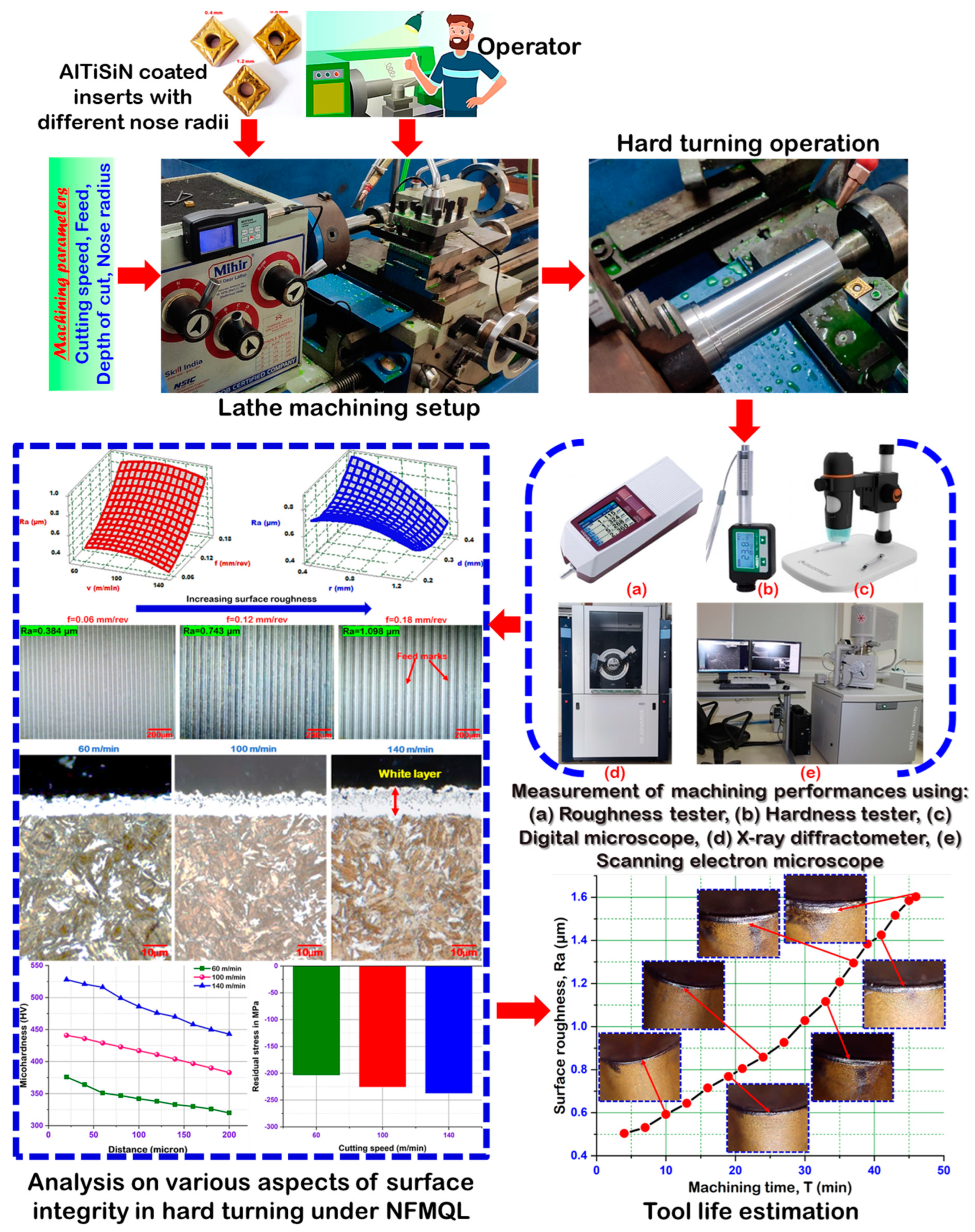
Graphical Abstract

1. Introduction

AISI 4140 is a high strength low alloy (HSLA) steel, suitable for a wide variety of applications in the manufacturing field of gears, crankshafts, collars, machinery parts, dies, etc., due to its excellent properties. Some of them also include high fatigue strength, abrasion and impact resistance, hardness-to-elasticity ratio, toughness, and torsional strength [1], leading to the category of hard-to-machine metal. Steel materials that are difficult-to-machine have always presented a troublesome task for the metal cutting industries. The fundamental criterion towards enhancing the machinability of hard-to-cut alloys under a dry environment is the selection of suitable tool materials (such as ceramic and CBN) to provide prolonged tool life. The tool wear could be reduced by supplying coolant and lubrication appropriately on the machining zone. At high cutting speed, the benefits of lubricant/coolant-based machining become most apparent because of the improved surface finish, reduced cutting temperature, and extended tool life. In recent years, various strategies, such as the application of cutting fluids, to improve the machining process have received considerable attention. Various research studies have employed oil-based cutting fluid during the machining of hard-to-cut metals [2]. However, there may be more drawbacks than benefits associated with using cutting fluids due to issues (health hazard) that develop during operation and the potential environmental harm caused by the disposal of used coolant. Furthermore, coolant cost is one of the considerable costs in manufacturing. Accordingly, industries are moving toward techniques that are more cost-effective and less harmful to the environment, such as traditional dry machining (which does not require cutting fluid) in conjunction with the development of efficient tooling systems that follow green and sustainable production philosophies [3]. We propose a new cooling strategy called MQL which involves to reduce the severe sliding at the contact region of tool-workpiece during machining, and significantly lowers temperature at the machining zone. MQL-based machining is an efficient bridging method between conventional flood cooling and environmentally friendly dry machining. Against other cooling strategies, this method is also environmentally friendly and clean. Based on this, researchers have widely employed different cooling strategies to enhance the machinability of various hardened steels. Naigade et al. [4] studied the surface roughness, chip morphology, cutting force and machined surface morphology during the hard machining of AISI 4340 steel under various cutting conditions using CBN inserts. Better results are obtained in the MQL condition, compared to other environments. Sahu et al. [5] performed the hard turning experiments on AISI 1015 steel and studied the tool-tip temperature, MRR, and surface roughness in both dry and spray impingement cooling improvement. It was observed that spray impingement cooling outperformed dry cutting in every aspect. Chinchanikar and Choudhury [6] studied the wear mechanisms of different coated carbide inserts under dry and MQL cutting conditions. Out of three coatings, the nano crystalline AlTiCrN coated tool outperformed other tools. Moreover, a better tool life was achieved through MQL, compared to dry cutting. Sharma et al. [7] compared the cutting temperature and surface roughness using the MQL technique with conventional coolant and nano coolant during the turning of AISI D2 steel. Results showed that MQL with a nano fluid outperformed MQL with a conventional coolant. The hardened steels with various hardness were machined using carbide inserts under dry and high-pressure cooling environments by Mia and Dhar [8]. Roughness, tool wear, and cutting temperature are studied. High pressure coolant application outperformed dry cutting in every aspect. Abbas et al. [9] performed the turning operation on AISI 1045 steel under three cutting environments and compared the results. Results involved the power consumption and surface roughness. From the results, it was observed that MQL with a nano fluid outperformed two other cutting environments, i.e., dry and flooded cooling, in every aspect. Hard turning experiments are conducted in three different cutting environments by Elbah et al. [10]. Tool wear, surface roughness, and cutting force were considered in the results. Better results, in terms of all reactions are obtained using MQL, compared to the other two cutting conditions. Speed influenced roughness whereas, depth of cut influenced cutting force. Masoudi et al. [11] investigated the effect of three cutting environments and cutting parameters on surface topography, cylindricity tolerance, cutting force, and sustainability. The results showed that the MQL cutting environments outperformed the other cutting environments regarding the results. With speed and feed, the cylindricity tolerance was found to be increased. Das et al. [12] performed the turning operation on hardened alloy steel using cermet inserts in three different cutting environments. Various responses, such as tool wear, micro hardness, roughness, machined surface, chip morphology, etc., were studied. The results showed that MQL with a nano fluid outperformed both compressed air cooling and a water-soluble coolant in every aspect. Das et al. [13] studied machining forces, tool flank wear, and chip thickness under three distinct cutting conditions, i.e., compressed air, water soluble coolant, and nano fluid. Depth of cut and speed greatly influenced the cutting force. Out of three cutting conditions, MQL performed better than the other two cutting conditions. Gupta et al. [14] conducted the hard turning operation in two cutting environments, i.e., dry and MQL. They studied flank wear, interface temperature, surface roughness, and chip morphology. Olive oil was used in the MQL. Results showed that during the MQL machining, the least amount of tool wear, temperature, and surface roughness were obtained, compared to the dry condition. Ondin et al. [15] investigated various machining characteristics of stainless steel under three different cutting environments. Surface roughness, topography, cutting temperature, and tool wear were considered in the results. Out of three cutting conditions, an MWCNT mixed nano fluid outperformed the other two cutting environments, i.e., dry and MQL without nano additives. Krolczyk et al. [16] studied various research articles on sustainable machining activities for hard and difficult to cut materials. Finally, they reported the following points: (1) More emphasis must be given to high pressure cooling activities during the machining of hard and difficult to cut materials, (2) dry cutting was found to be a good alternative, as coolant will not be used. Therefore, both cost and hazards to workers and the atmosphere can be reduced, (3) MQL and MQCL are found to be the best modes for the coolant delivery to the machining zones, and (4) nanofluid was observed to be a very good alternative as a cutting fluid in different machining operations for hard and difficult to cut materials. Maruda et al. [17] conducted the turning operation on stainless steel under five different cutting environments. Surface roughness was considered for the output result. The results showed that the least amount of roughness was achieved when a coolant was mixed with emulsifier and modifier and applied to the machining zone. Shah et al. [18] conducted the experiments on stainless steel in four different cutting conditions, such as dry, electrostatic lubrication, electrostatic MQL, and hybrid nano particle-assisted EMQL. The cutting force, power consumption, surface roughness, and chip reduction coefficient were examined. From the results, it was observed that hybrid nano particle-assisted EMQL performed better in terms of all results, compared to other cutting conditions. Sankaranarayanan et al. [19] critically reviewed various research articles based on biodegradable cutting fluid applications in different machining activities. As biodegradable cutting fluids are environmentally friendly or hazardous free, they concluded their analysis with the following observations: (1) With the use of a metal cutting fluid, the cost of machining will be increased. Moreover, disposal of such metal working fluid is critical, (2) a vegetable oil-based cutting fluid performed superiorly in various machining activities, compared to other fluids, (3) more emphasis and research must be carried out on the application of different vegetable oil-based biodegradable coolants in different machining activities.
For turning hard-to-machine alloy materials, high-priced ceramic, polycrystalline diamond (PCD), and cubic boron nitride (CBN) cutting tools are commonly used in view of their excellent properties and longer tool life [20]. However, these materials are not a viable option for cutting tools due to their high cost. A coated tool is a suggested strategy for overcoming these limitations. In recent decades, tool coating has exploded in popularity as a cost-effective alternative to replacing tools in dry machining [21]. Coatings are applied to the surface of the tool substrate to reduce the friction coefficient and to improve the wear resistance (sometimes both). This allows the tool to be operated at a high cutting speed for attaining an improved machined surface quality and reducing the cutting forces, machining temperature, as well as tool wear [22]. With a view to improve the properties and cutting performance of an uncoated insert’s surface, coating techniques, including chemical vapor deposition and physical vapor deposition are commonly employed. The majority of the commercially available coating materials, namely TiN, TiC, TiCN, TiAlN, Al2O3, AlCrN, and AlTiN, which are deposited on the carbide tool substrate, are utilized for the machining of steel [23,24,25,26,27,28,29,30]. However, it is absolutely necessary to choose an appropriate coating material for the improvement of tool life, as well as the surface quality while machining the hardened alloy steels. In order to determine the most suited coating material, in respect to a particular workpiece, numerous studies have been published so far detailing the use of a wide range of coated carbide tools [31,32,33,34] in the dry machining of difficult and hard-to-machine materials.
By reviewing the literature, it was found that, a nanofluid application under MQL is one of the techniques that can efficiently manage the machining performances in hard turning and this needs to be investigated further. Owing to the wide spread demand of low cost coated carbide tools in metal cutting industries, more attention and more studies are required to improve the surface integrity in the machining of various hardened steels, which is beneficial from the economical perspective. To the best of the author’s knowledge, the utilization of an SPPP-AlTiSiN coated insert in hard turning has rarely been discussed in the literature [34,35,36]. This research study aims to analyze the surface integrity in the hard turning of AISI 4140 HSLA steel with a recently established SPPP-AlTiSiN coated carbide insert under MQL using ZnO nanoparticles blended in an automotive radiator coolant. The analysis addresses the various aspects of surface integrity concerning surface morphology, machined surface hardness, residual stress and white layer development, and machined surface quality (especially, Ra) under varying geometrical parameters (nose radius) and cutting parameters (depth of cut, speed, feed) of the insert. The RSM is implemented for predictive modelling and optimization in order to accomplish the minimum amount of surface roughness. Finally, an economic assessment is addressed to justify the cost effectiveness of the coated carbide tool for the hard turning application. All of these contributions proposed in the current analysis explore a new avenue of research.

2. Experimental Setup and Procedure

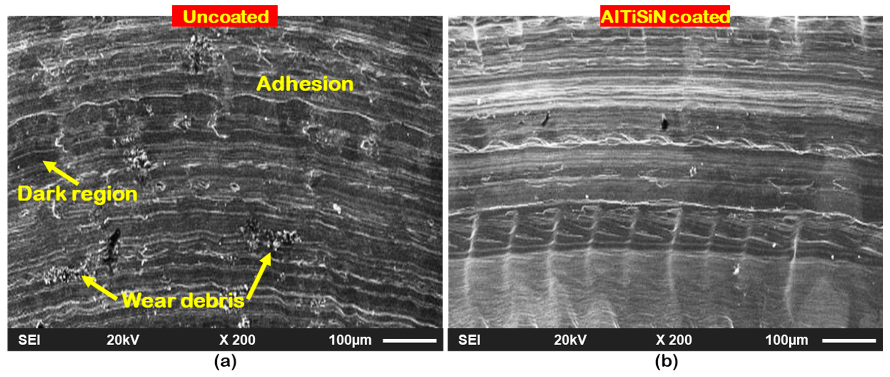
To evaluate the surface finish in hard turning, a cylindrical heat-treated bar made of HSLA grade AISI 4140 steel, possessing a hardness of 51 HRC and with dimensions of 45 × 200 (diameter 45 mm and length 200 mm), is machined on a heavy-duty lathe (Mihir 250X). Figure 1 depicts the microstructure and EDS result of the material investigated in this study. Additionally, Table 1 presents the various properties of the workpiece materials. A recently developed ultra-hard thin monolayer of AlTiSiN coating deposited on a carbide tool substrate with the help of the scalable pulsed power plasma (SPPP) method, is considered as a cutting material. The details for the procedure of the S3P technique concerning a AlTiSiN nanocomposite coating has been discussed by Das et al. [35]. In the work of Mahapatra et al. [36], the SEM observation followed by the EDS analysis confirmed the morphology and chemical constituents of the AlTiSiN coating layer. The wear scar morphology of the AlTiSiN coating was characterized by comparing it with the uncoated carbide tools using optical microscopy, in order to evaluate the coating layer performance. The diameters and depth of wear scar for both inserts are illustrated in Figure 2. The wear scar was more prominent and deeper for the uncoated inserts, in comparison with the AlTiSiN coated inserts. Due to superior hardness and anti-friction properties provided by the protective coating layer, better results are obtained for the AlTiSiN coating. The SEM images of the wear tracks on the AISI 4140 steel counter faces after the pin-on-disc tests under specific conditions (normal load = 20 N; sliding speed = 0.12 m/s; sliding distance = 188 m), against the uncoated and AlTiSiN coated pins are shown in Figure 3a,b, respectively. The dark regions suggest that the surfaces were slightly oxidized during the test. Figure 3a suggests a smoother surface and reduced wear on the counter face after the test against the AlTiSiN coated pin. Interestingly, the worn surface became rougher and showed signs of plastic deformation after contact with the uncoated pin, see Figure 3b. The wear was clearly more severe on this track. Thus, the higher specific wear coefficient of the tribopair (uncoated carbide-AISI 4140 steel) may have been favoured by the attraction between the materials. ISO standard CNMG 1204×× coated carbide cutting inserts of three different nose radii were clamped in a tool holder (PCLNL 2020K12). The combination of the cutting insert with the tool insert holder resulted in the cutting geometry of −5°- −5°- 5°- 5°- 5° - 95° (i.e., −5° back rake, −5° side rake angle, 5° end clearance angle, 5° side clearance angle, 5° end cutting edge angle, and 95° approach angle). For nanofluid-MQL machining, the automotive radiator coolant (made by Wurth) was utilized as the base fluid. Table 2 shows the properties of the green radiator coolant used as the base cutting fluid in this study. The nanofluid was developed by mixing a base coolant (1000 mL) and fewer than 60 nm sized nanoparticles of zinc oxide, ZnO (5 mg) in a magnetic stirrer followed by ultrasonication, in order to improve the homogeneity of the solution. Figure 4 schematically illustrates a step-by-step process for preparing the nanofluid.
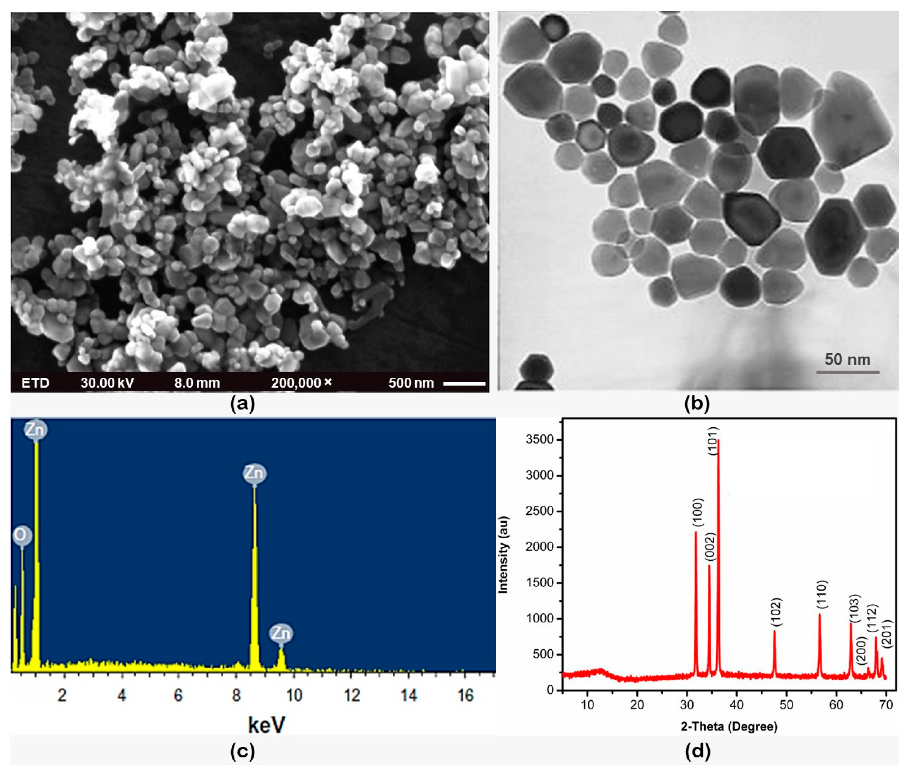
The morphological attributes of the zinc oxide nanoparticle were studied using SEM, as well as transmission electron microscopy (TEM), as illustrated in Figure 5a,b, respectively. Well dispersed nanoparticles with a globular structure with spherical shape were observed. The average size was below 60 nm. To examine the nanoparticles, regarding their exact and accurate shape, a TEM analysis was conducted and from the image, it was observed that the shape of the nanoparticle was spherical without any kind of sharp edges. Only one type of grain structure was observed. Using energy dispersive X-ray spectroscopy, the composition of the nanoparticles was studied. With the presence of O and Zn signals, from Figure 5c, it was confirmed that the nanoparticle was zinc oxide. Further, the nanoparticle was analyzed using an X-ray diffraction spectroscope, which is shown in Figure 5d. It was observed that the nanoparticle’s structure was crystalline. Moreover, with the search and match facility of X’ pert high score software, the zinc oxide nanoparticles were identified as JCJCPDS (reference code: 01-079-2205). From the XRD image, it was confirmed that the zinc oxide nanoparticles contained a hexagonal crystal structure. From the X-ray diffraction data, it was confirmed that the structure of the sample was crystalline and the peaks were observed at different 2θ values i.e., 32, 36, 37, 47, 56, 63, and 69 degrees with different indices, such as (100), (002), (101), (102), (110), (103), (200), (112), and (201).
The average roughness (Ra) of the machined surfaces under different cutting settings was determined by a roughness testing device (Mitutoyo Surftest SJ-210). The machined surface hardness and developed residual stresses were measured by a portable hardness tester (Insize HDT-L411) and an XRD machine (Bruker D8 ADVANCE), respectively. Additionally, a scanning electron microscope (Quanta 250-FEG), and digital microscope (Celestron 44308-DS) were employed, respectively, for the evaluation of the machining performances, including the machined surface quality and the tool’s flank wear. Each test was performed at a machining length of 180 mm under different cutting variables. The variable process parameters were the depth of cut, cutting speed, nose radius, and feed. The range and levels of the parameter variations are shown in Table 3. The choice of the Box–Behnken design for the four factors at three levels and the experimental layout associated with 30 trials was adopted. Table 4 exhibits the detailed experimental plan layout and the results of the surface roughness under different cutting conditions. Figure 6 manifests a detailed schematic of the experimental setup and procedure.

3. Results and Discussion

3.1. Model Prediction Using the Response Surface Method

With a view to establish a relationship between the cutting variables (v, f, d, r) and surface roughness (Ra), the results of several machining trials conducted in line with the BBD experimental design are analyzed by employing the RSM. The developed RSM model is provided in the form of a second order regression equation as:
Ra = 0.424 + 0.00750v − 1.08f − 6.05d + 1.772r − 0.000042v2 + 23.49f2 + 10.21d2 0.418r2 + 0.00706v*f + 0.00267v*d − 0.001770v*r + 10.80f*d − 5.372f*r − 1.905d*r
R-sq = 97.50%, R-sq (adj.) = 95.17%
To avoid the misleading outcome, a different diagnostic analysis verifies the efficiency of the presented model. An ANOVA analysis (Table 5) confirms that the predictive model has an excellent significance owing to high value of the correlation coefficient (R2= 0.975) and a low probability (p) value within a 95% confidence interval. Moreover, the predicted and experimental values for Ra are observed to be in excellent proximity, as shown in Figure 7a. This indicates that the suggested models have a strong predictability. The null-hypothesis cannot be dismissed, as confirmed by the Anderson–Darling test linked to the normal distribution probability plot shown in Figure 7b, where the AD-test p-value of 0.068 is exceeding the value of 0.05. Furthermore, the distribution of residuals is normal (i.e., it is close to the standard line), demonstrating the goodness for fit-of-data. Conclusively, various diagnostic analyses (normality test, predictability test, ANOVA analysis) confirmed that the prediction of the developed model for surface roughness has a good conformity with the experimental results and the model is accurate, which indicates that this hard turning process should be further considered for its application.

3.2. Analysis on the Surface Integrity

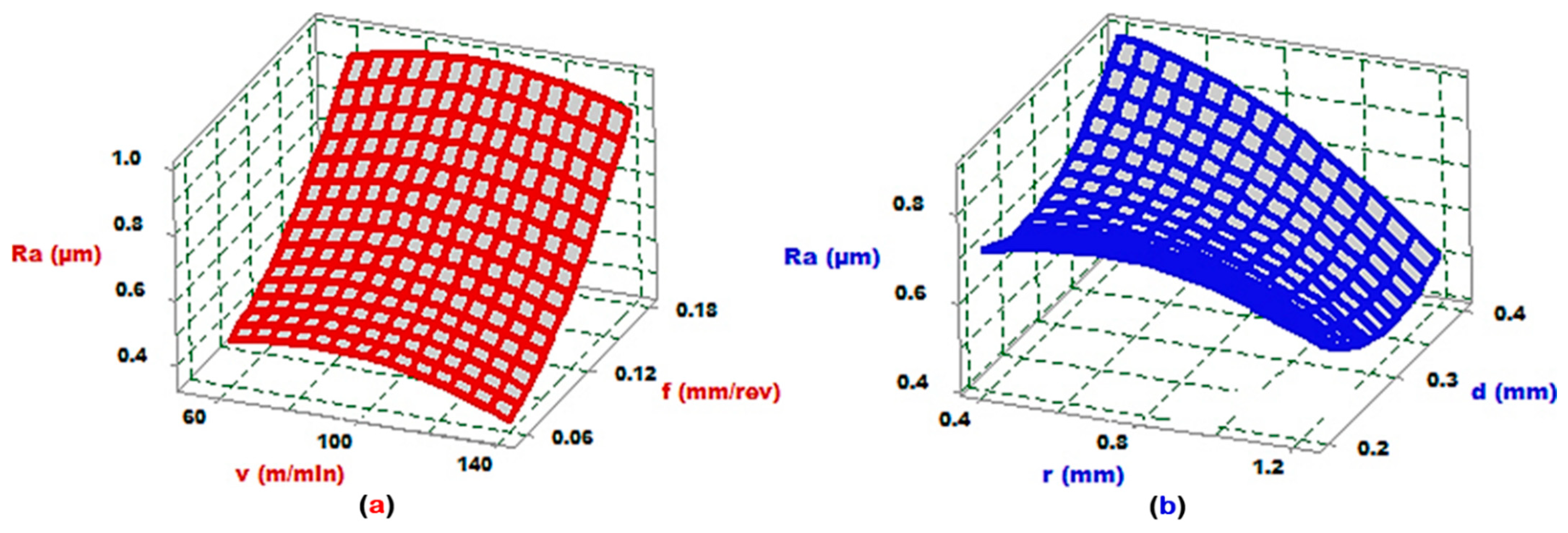
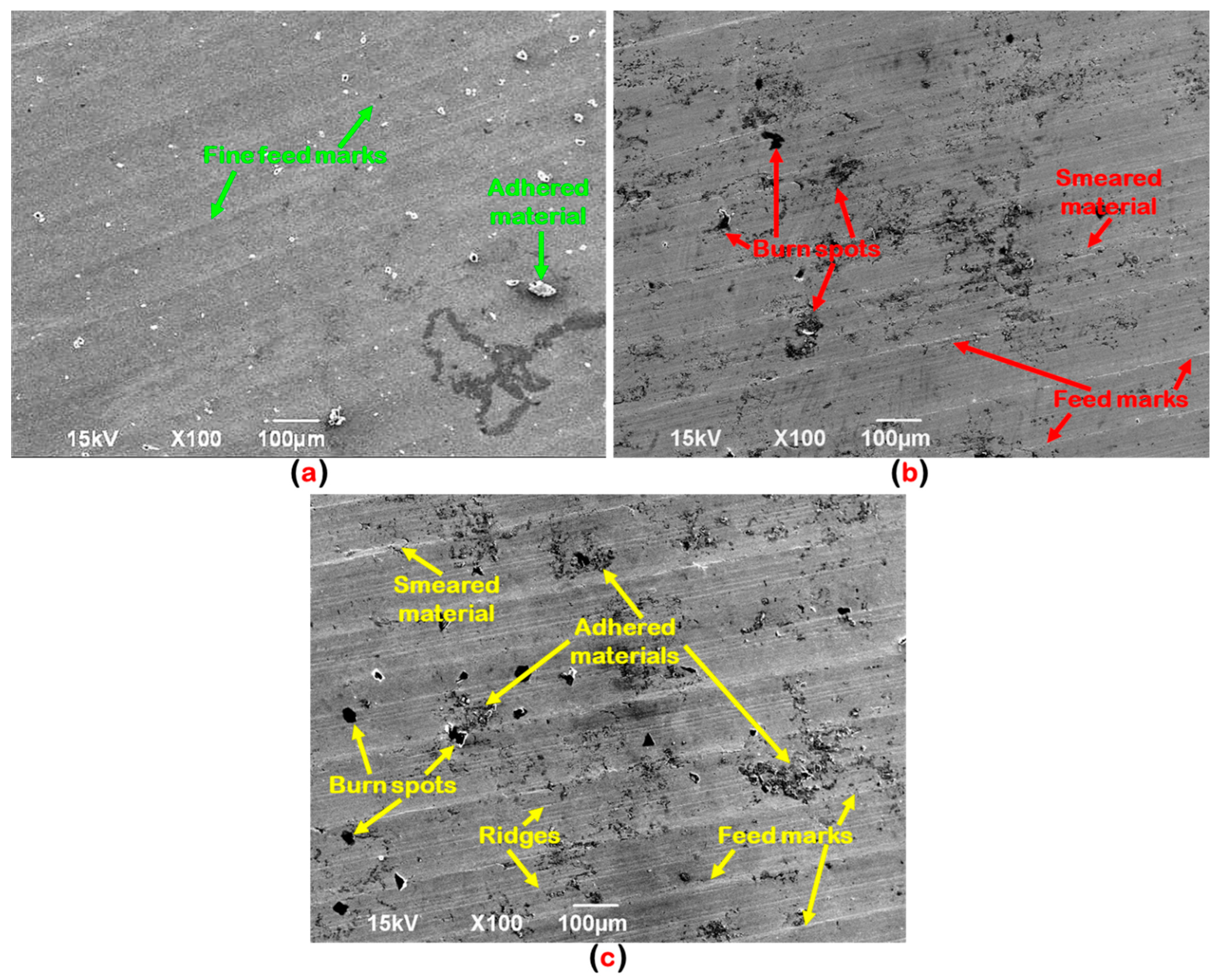
This work analyzes the various aspects of the surface integrity concerning the surface morphology, the machined surface hardness, residual stress and white layer development, and machined surface quality (especially, Ra). Three-dimensional response surface plots are provided to graphically analyze the effect of the different machining factors (speed, feed, doc, nose radius) on the machined surface finish (Ra). The experiment of the surface roughness at varying feed rates, as illustrated in Figure 8a, confirms the widely accepted mathematical relationship of the theory of machining ( R a = 0.0321 × f e e d 2 n o s e   r a d i u s ) [39]. This effect is caused by the ploughing action creating wider and deeper helicoid furrow footprints on hard turned surfaces (marked by the tool nose tip and the relative motion of the tool-work pair) [40,41]. This outcome is confirmed by microscopical observations at varying feed rates (see, Figure 9). An increase of feed rate leading to a larger shear plane area with a shorter interaction time at the machining zone. As a result, the tool moves rapidly over the work surface which reduces the machining efficiency and thereby, resulting poor surface quality due to the development of intense feed marks on the machined surface. Figure 10 describes the status of the machined surface with regard to the material side flow (due to severe plasticization of the turned surface), feed marks (due to the resultant nose shape helicoid tool-workpiece movement), grooves and ridges (attributed to the shearing as well as ploughing effect of the workpiece by broken hard abrasive particles under the cutting edge), adhered material (due to the cohesion issue in the hard turned surface caused by the great amount of heat generation and cold-welding effect). Moreover, Keblouti et al. [42] reported that the tangential force needed for the material removal increases with the increase of feed which accelerates the tool vibration and leads to a degradation in the surface finish. The convective and evaporative heat transfer in the minimum quantity lubrication condition leads to the rapid cooling of the machined surface and the formation of untempered martensite. Consequently, the surface hardness might be increased which leads to a rougher machined surface with the increase of the feed rate, as reported by Das et al. [43]. Figure 8a depicts that with the increase in the cutting speed, the surface finish improves, possibly caused by the restriction of the material side flow [44] and due to the diminishing chatter formation caused by the self-induced vibration [35]. Additionally, this outcome is explained by the phenomenon of thermal softening occurring at high temperatures leading to the reduction in the machining forces [45] and thereby, resulting in a minimum value of Ra.
Surface roughness is also influenced by other factors, including the depth of cut and nose radius, as is evident in Figure 8b. It is seen that the increase in the tool nose radius leads to an improvement in the surface finish. It happened due to the increase of the effective length of the cutting edge which minimizes the tool wear (refer, Figure 11). Thereby, it results in a low Ra value. That means, when the machining was performed with a small nose radius tool, fracturing and chipping were observed, which is an unusual type of tool wear that is considerably rare for tools with a large nose radius. In the small nose radius, the decreased shear area might lead to a high shear stress in both axial and tangential directions. However, with a larger nose radius, the shear deformation area will be greater, with less stress in both of the above-mentioned directions, thus, leading to no unusual tool wear or tool vibration. Moreover, the primary cause of this outcome is due to the development of less stress and heat generation under a high nose radius, compared to a small edge corner radius, which makes it possible for the heat to disperse more rapidly by lowering the elevated temperature developed at the cutting edge, thereby resulting in an improved surface finish [46]. Additionally, a large nose radius results in a high level of roundness at the tool tip, which removes footprints of the feed mark left by the earlier shearing action and attains an improved surface quality. In their experimentation, Panda et al. [47] noted similar observations. Thakur et al. [48] stated that owing to the involvement of high cutting forces, these induce a residual stress distribution in the form of a work-hardened layer during the machining with a smaller nose radius, which is responsible for more power consumption, as well as surface roughness. As demonstrated in Figure 8b, followed by the ANOVA, the effect of the doc appears to have little impact (insignificant) on the surface finish of the hard turned part. Furthermore, the work material’s hardness is greater than 40 HRC and is made up of hard precipitated elements of several carbides (Mo2C, Cr7C3, Fe3C, VC) at the microstructural level during its heat treatment [49]. As a result, it provokes severe squeezing and edge depression at the vicinity of the cutting tip under high doc. This causes a greater self-induced vibration, and impacts the cutting performance concerning the tool wear. Thus, to avoid chatter caused by vibration, it is recommended that the depth of cut is set to a lower value in hard machining [49]. Similar observations have been reported in the study by Rafighi et al. [41].
The recently established SPPP-AlTiSiN coated carbide tool enhanced the machining performance by experiencing a lower surface roughness (Ra) range of 0.264 to 1.385 µm, as compared to those obtained in machining by cylindrical grinding and other finishing operations. This was possible, in view of the excellent cooling and lubrication capability of the nanofluid-MQL and due to the improved features (wear resistance, hot hardness, coefficient of friction, and heat dissipation ability) of the AlTiSiN coating material [35].
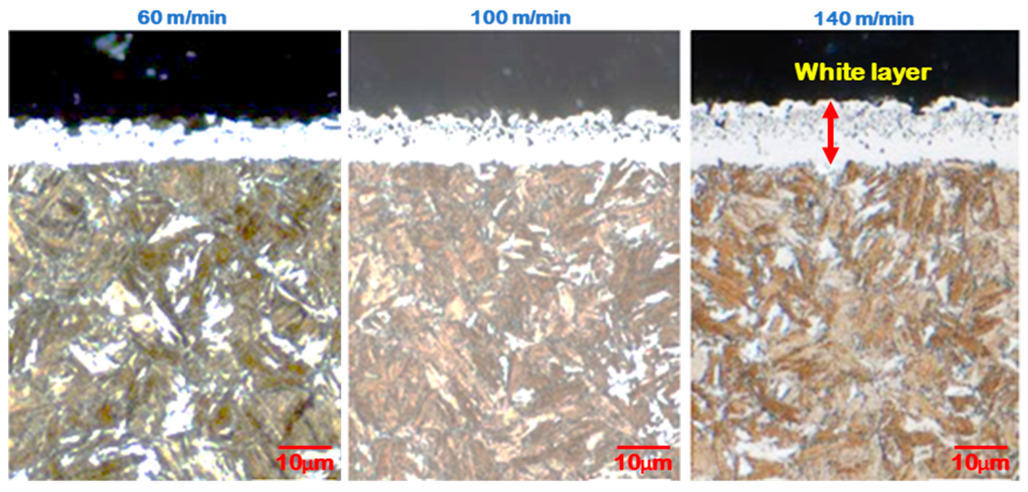
Figure 12 presents the micrograph images of the hard turned surface of main and sublayer regions while using an AlTiSiN coated tool under NFMQL. Based on the observations, it is noticed that the white layer thickness on the machined surfaces increases while the speed in the studied range increases (i.e., 60–140 m/min). Rapid heating and quenching, surface alteration caused by severe plastic deformation are the principal mechanisms that affect the white layer development on the hard turned surfaces [50]. The increase in speed causes a rapid increase of temperature at the machining zone, and results in an expansion of the white layer due to insufficient heat transfer and intense shear deformation. The limited heat conductivity of the hardened steel material is responsible for this increase of white layer thickness and for this reason results in the occurrence of the maximum tool flank wear at a high cutting speed [34].
Convective and evaporative heat transfers are responsible for the formation of unaltered martensite in MQL machining, which enables the rapid cooling of machined surfaces. As a result, the surface hardness increases. Furthermore, the cutting variables typically have an impact on the work hardening intensity on the machined surfaces. In this research, the influence of the cutting speed on the hardness of the main layer and sublayers of the machined surface are analyzed while nanofluid-MQL machining with an AlTiSiN coated tool. It is evident from Figure 13a, that the main layer and sublayers of the machined surfaces have notable hardness variations while the cutting speed changed (60–140 m/min). Furthermore, the machined surface hardness increases with cutting speed. The microhardness decreases from the main layer (machined surface edge) to the sub-surface layer (i.e., in the direction of the center) because of the crystalline size variation among them caused by the elevated cutting temperature. The surface integrity is greatly affected by the residual stress which has an influential consequence on fatigue strength and corrosion resistance of the machined parts. The residual stress therefore seems to be an important aspect for this investigation. Figure 13b depicts the consequence of the cutting speed on the developed residual stress of the machined surface while nanofluid-MQL machining with an AlTiSiN coated tool. Over the studied range of cutting speeds, the compressive residual stresses are identified. Furthermore, the developed residual stresses on the machined surface increased with the increase in cutting speed. Three factors normally influence the residual compressive stress layer: cutting force, cutting temperature, and increment of friction. With the increment of friction, both force and temperature increase. With the increment of the cutting speed, the temperature at various machining zones increases because of the insufficient heat transfer to the surroundings within the stipulated duration of cutting. Tool wear at both the flank and rake surfaces is the possible cause for the higher value of the compressive residual stress. The primary reason for the increment of the residual stress is the alteration of the microstructures that leads to a change in the mechanical properties because of the high temperature generation and friction. All of the above findings are consistent with the research conducted by Leppert and Peng [51] and Liu et al. [52]. Friction and temperature are the two important factors which are mainly responsible for the generation of residual stress during machining. When the feed rate increases, leading to more contact between tool and work, it results in more friction and heat generation. Moreover, as the friction is greater, it will affect the tool life. Additionally, when machining is accomplished with a worn out insert, more heat will be generated. Thus, more compressive residual stress might be generated. However, in comparison to the cutting speed, less residual compressive stress was induced (Figure 13c).

3.3. Optimization Using the RSM

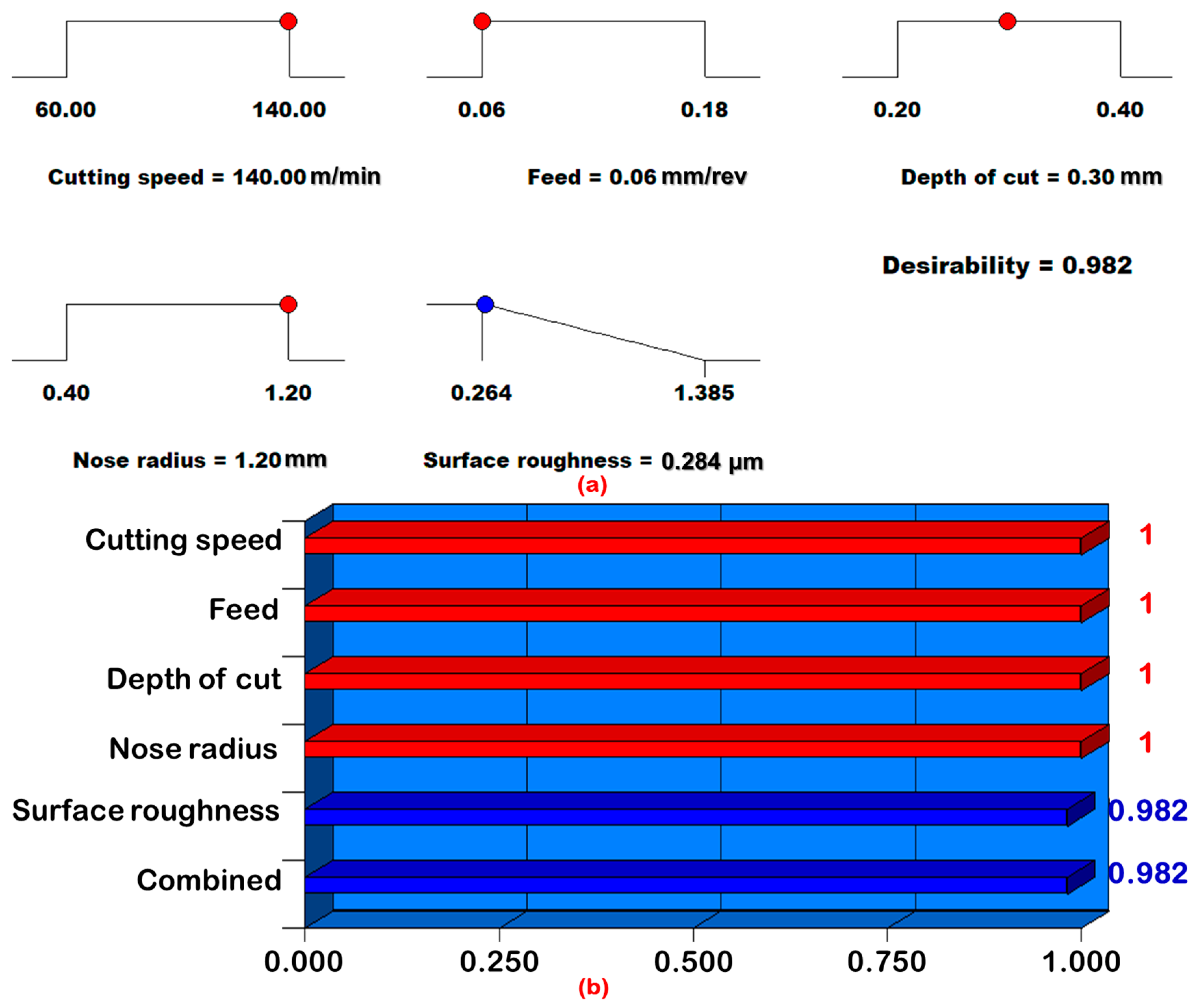
This study employed the desirability function analysis as an optimization approach aiming to minimize the surface roughness Ra. In this technique, the criterion to achieve the optimization result is assessed using the desirability value, which is expressed within the scale free range of 0–1. A desirability of zero (i.e., an elementary desirability with a value of 0) reflects an undesirable condition for the response, whereas a desirability of 1 represents the ideal or desirable case [53]. The best condition with the highest desirability value (close to one) is considered to be represented on the ramp function graph among the forty-two possible solutions to the optimization problem, as shown in Figure 14a. On each ramp plot, the red colour spots reflect the cutting variable combinations that are most desirable. The bar chart in Figure 14b shows the individual desirability values for each cutting variable and the responses (Ra) that are close to 1. The best conditions for the hardened AISI 4140 steel machining is presented in the optimization plot using the desirability function analysis at a cutting speed of 140 m/min, feed of 0.06 mm/rev, depth of cut of 0.3 mm, and nose radius of 1.2 mm under nanofluid-MQL. The optimal value of the surface roughness is 0.284 µm.

3.4. Cost Analysis

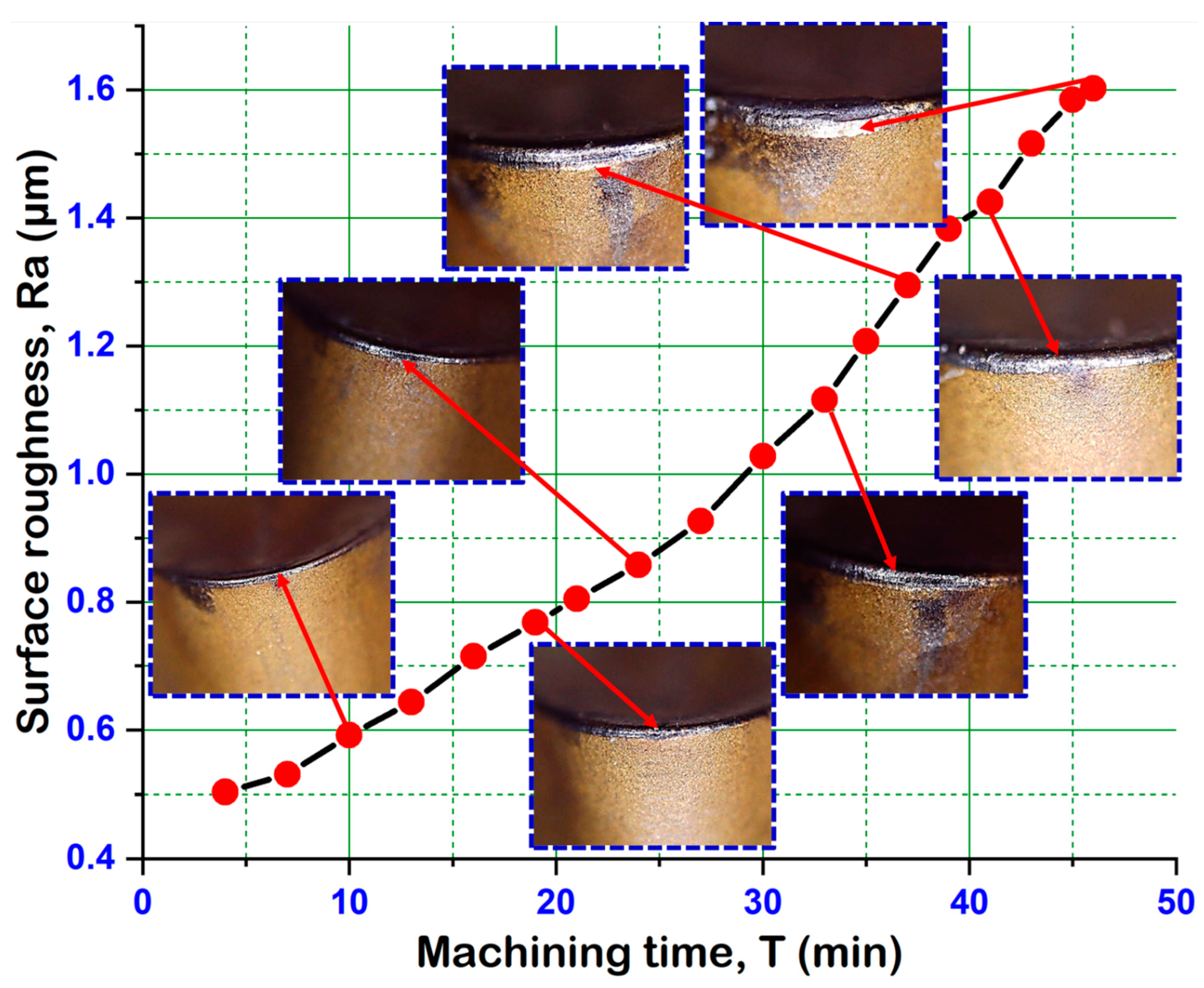
In this section, an economic analysis was performed under nanofluid-MQL using a SPPP-AlTiSiN coated carbide tool. Therefore, further experimental trial runs were performed to ascertain the tool life of the coated carbide inserts with the same experimental setup. The additional trial was conducted under optimum machining parameter settings, as suggested by the RSM, aiming to estimate the lifespan of the carbide insert based on the ISO 3685 tool life criterion (i.e., roughness, Ra value up to 1.6 µm). Figure 15 illustrates the development of the flank wear in the coated carbide tool with machining duration until the Ra approaches to 1.6 µm under NFMQL. The life of the SPPP-AlTiSiN coated carbide insert ended at 46 minutes. With consideration of the estimated tool life, Table 6 presents the economic assessment that measures the overall machining cost per component in accordance with Gilbert’s method [54,55]. The assessment of the cost analysis calculating the overall machining cost per component is Rs.23.12 under nanofluid-MQL using a SPPP-AlTiSiN coated carbide insert.

4. Conclusions

In this study, experimental trials were carried out to investigate the surface integrity and economic assessment under a nanofluid-MQL condition when machining hardened AISI 4140 steel with a recently developed AlTiSiN coated carbide tool. Furthermore, a statistical analysis was performed along with the development of a predictive model and optimization of the surface roughness. The approach for the exploration of surface integrity improvement proposed in this work, finds itself a new avenue of research on hard turning. The findings of this work: (i) the proposal of an alternative to the costlier ceramic and CBN tools by utilizing a low-cost, newly developed SPPP-AlTiSiN coated carbide tool in hard turning applications from a techno-economical perspective, which is helpful and efficient from an industrial point of view, (ii) contribution to practical industrial application of finish turning for mould and die makers to select the appropriate cutting conditions in a range of hardness of 45-65 HRC, (iii) offers worthy investigations towards the efficiency of a ZnO nanoparticle-enriched cutting fluid in hard turning for suitability in environmentally friendly applications in machining industrial sectors, and (iv) help to improve the desirable machinability characteristics. The following conclusions are discussed based on the results obtained from the present experimental investigations.
The results demonstrate that increasing feed under a nanofluid-MQL condition is the most dominant parameter for increasing the surface roughness. Furthermore, as the cutting speed increases, the surface finish improves. The analysis of the results confirms that the machined surface quality improves with the increase of the nose radius due to the occurrence of minimum tool wear and due to the increase of the effective length of the cutting edge. Moreover, the increase of the nose radius can cause the decrease of the theoretical residual area on the machined surface. This is the main reason for the decrease of the surface roughness. Distinctive diagnostic analyses (normality test, predictability test, ANOVA analysis) confirmed that the prediction of the developed model for the surface roughness under nanofluid-MQL has a good resemblance with experimental results and the model is accurate. The optimization result based on the desirability function approach illustrates the optimum surface roughness of 0.284 µm in the turning of HSLA steel at doc of 0.3 mm, speed of 140 m/min, feed of 0.06 mm/rev, and tip radius of 1.2 mm under nanofluid-MQL. At optimum cutting conditions (expressed via RSM), the tool life of the SPPP-AlTiSiN carbide insert (as per ISO 3685, the roughness Ra value up to 1.6 µm) is considerably noted as 46 minutes under nanofluid-MQL and as a result, it estimates that the overall machining cost per component is INR 23.12, which is economically feasible. The recently established SPPP-AlTiSiN coated carbide tool enhanced the machining performance by experiencing a lower surface roughness (Ra) range of 0.264 to 1.385 µm, as compared to those obtained in machining by cylindrical grinding and other finishing operations. This was possible in view of the effective cooling and lubrication capability of NFMQL and due to the improved features (wear resistance, hot hardness, coefficient of friction, and heat dissipation ability) of the AlTiSiN coating material.
In terms of future work, considering the limitations of this research, more in-depth studies can be extended to analyze the influence of some additional variables, such as the type of coating materials, other cooling-lubrication methods, and machining time to improve the various machine characteristics. Further investigations can be carried out to assess the effects of the process parameters on the power consumption, tool wear, cutting temperature, and cutting force. Furthermore, investigations are still required for different machining conditions to roundly explore and compare the potential of nanofluid-MQL, and to understand the thermo-physical, as well as tribological behaviors when machining with nanofluids. Although the results are adequate, this study can be extended for further applications of other optimization techniques for the comprehensive understanding for the selection of appropriate machining conditions and the control of various technological responses.

Author Contributions

Conceptualization, S.P. and N.K.W.; methodology, software, validation, N.K.W., P.S. and S.R.D.; formal analysis, A.D. and P.S.; investigation, L.D. and S.R.D.; resources, M.R.; writing—original draft preparation, S.P., L.D. and A.D.; writing—review and editing, S.R.D.; supervision, S.R.D., A.D. and M.R. All authors have read and agreed to the published version of the manuscript.

Funding

This research received no external funding.

Conflicts of Interest

The authors declare no conflict of interest.

References

  1. Das, S.R.; Dhupal, D.; Kumar, A. Experimental Investigation into Machinability of Hardened AISI 4140 Steel Using TiN Coated Ceramic Tool. Meas. J. Int. Meas. Confed. 2015, 62, 108–126. [Google Scholar] [CrossRef]
  2. Liew, P.J.; Shaaroni, A.; Sidik, N.A.C.; Yan, J. An Overview of Current Status of Cutting Fluids and Cooling Techniques of Turning Hard Steel. Int. J. Heat Mass Transf. 2017, 114, 380–394. [Google Scholar] [CrossRef]
  3. Debnath, S.; Reddy, M.M.; Yi, Q.S. Environmental Friendly Cutting Fluids and Cooling Techniques in Machining: A Review. J. Clean. Prod. 2014, 83, 33–47. [Google Scholar] [CrossRef]
  4. Naigade, D.M.; Patil, D.H.; Sadaiah, M. Some Investigations in Hard Turning of AISI 4340 Alloy Steel in Different Cutting Environments by CBN Insert. Int. J. Mach. Mach. Mater. 2013, 14, 165–173. [Google Scholar] [CrossRef]
  5. Sahu, S.K.; Mishra, P.C.; Orra, K.; Sahoo, A.K. Performance Assessment in Hard Turning of AISI 1015 Steel under Spray Impingement Cooling and Dry Environment. Proc. Inst. Mech. Eng. Part B J. Eng. Manuf. 2015, 229, 251–265. [Google Scholar] [CrossRef]
  6. Chinchanikar, S.; Choudhury, S.K. Hard Turning Using HiPIMS-Coated Carbide Tools: Wear Behavior under Dry and Minimum Quantity Lubrication (MQL). Meas. J. Int. Meas. Confed. 2014, 55, 536–548. [Google Scholar] [CrossRef]
  7. Sharma, P.; Sidhu, B.S.; Sharma, J. Investigation of Effects of Nanofluids on Turning of AISI D2 Steel Using Minimum Quantity Lubrication. J. Clean. Prod. 2015, 108, 72–79. [Google Scholar] [CrossRef]
  8. Mia, M.; Dhar, N.R. Optimization of Surface Roughness and Cutting Temperature in High-Pressure Coolant-Assisted Hard Turning Using Taguchi Method. Int. J. Adv. Manuf. Technol. 2017, 88, 739–753. [Google Scholar] [CrossRef]
  9. Abbas, A.T.; Benyahia, F.; El Rayes, M.M.; Pruncu, C.; Taha, M.A.; Hegab, H. Towards Optimization of Machining Performance and Sustainability Aspects When Turning AISI 1045 Steel under Different Cooling and Lubrication Strategies. Materials 2019, 12, 3023. [Google Scholar] [CrossRef] [Green Version]
  10. Elbah, M.; Laouici, H.; Benlahmidi, S.; Nouioua, M.; Yallese, M. Comparative Assessment of Machining Environments (Dry, Wet and MQL) in Hard Turning of AISI 4140 Steel with CC6050 Tools. Int. J. Adv. Manuf. Technol. 2019, 105, 2581–2597. [Google Scholar] [CrossRef]
  11. Masoudi, S.; Esfahani, M.J.; Jafarian, F.; Mirsoleimani, S.A. Comparison the Effect of MQL, Wet and Dry Turning on Surface Topography, Cylindricity Tolerance and Sustainability. Int. J. Precis. Eng. Manuf.-Green Technol. 2019. [Google Scholar] [CrossRef]
  12. Das, A.; Das, S.R.; Patel, S.K.; Biswal, B.B. Effect of MQL and Nanofluid on the Machinability Aspects of Hardened Alloy Steel. Mach. Sci. Technol. 2020, 24, 291–320. [Google Scholar] [CrossRef]
  13. Das, A.; Patel, S.K.; Biswal, B.B.; Sahoo, N.; Pradhan, A. Performance Evaluation of Various Cutting Fluids Using MQL Technique in Hard Turning of AISI 4340 Alloy Steel. Measurement 2020, 150, 107079. [Google Scholar] [CrossRef]
  14. Gupta, M.K.; Mia, M.; Jamil, M.; Singh, R.; Singla, A.K.; Song, Q.; Liu, Z.; Khan, A.M.; Rahman, M.A.; Sarikaya, M. Machinability Investigations of Hardened Steel with Biodegradable Oil-Based MQL Spray System. Int. J. Adv. Manuf. Technol. 2020, 108, 735–748. [Google Scholar] [CrossRef]
  15. Öndin, O.; Kıvak, T.; Sarıkaya, M.; Yıldırım, Ç.V. Investigation of the Influence of MWCNTs Mixed Nanofluid on the Machinability Characteristics of PH 13-8 Mo Stainless Steel. Tribol. Int. 2020, 148, 106323. [Google Scholar] [CrossRef]
  16. Królczyk, G.M.; Maruda, R.W.; Królczyk, J.B.; Wojciechowski, S.; Mia, M.; Niesłony, P.; Budzik, G. Ecological trends in machining as a key factor in sustainable production—A review. J. Clean. Prod. 2019, 218, 601–615. [Google Scholar] [CrossRef]
  17. Maruda, R.W.; Legutko, S.; Krolczyk, G.M.; Hloch, S.; Michalski, M. An influence of active additives on the formation of selected indicators of the condition of the X10CrNi18-8 stainless steel surface layer in MQCL conditions. Int. J. Surf. Sci. Eng. 2015, 9, 452–465. [Google Scholar] [CrossRef]
  18. Shah, P.; Khanna, N.; Zadafiya, K.; Bhalodiya, M.; Maruda, R.W.; Krolczyk, G.M. In-house development of eco-friendly lubrication techniques (EMQL, Nanoparticles+EMQL and EL) for improving machining performance of 15–5 PHSS. Tribol. Int. 2020, 151, 106476. [Google Scholar] [CrossRef]
  19. Sankaranarayanan, R.; Rajesh Jesudoss Hynes, N.; Senthil Kumar, J.; Krolczyk, G.M. A comprehensive review on research developments of vegetable-oil based cutting fluids for sustainable machining challenges. J. Manuf. Process. 2021, 67, 286–313. [Google Scholar]
  20. Kumar, R.; Sahoo, A.K.; Mishra, P.C.; Das, R.K. Comparative Investigation towards Machinability Improvement in Hard Turning Using Coated and Uncoated Carbide Inserts: Part I Experimental Investigation. Adv. Manuf. 2018, 6, 52–70. [Google Scholar] [CrossRef]
  21. Goindi, G.S.; Sarkar, P. Dry Machining: A Step towards Sustainable Machining—Challenges and Future Directions. J. Clean. Prod. 2017, 165, 1557–1571. [Google Scholar] [CrossRef]
  22. Sousa, V.F.C.; Silva, F.J.G. Recent Advances in Turning Processes Using Coated Tools—A Comprehensive Review. Metals 2020, 10, 170. [Google Scholar] [CrossRef] [Green Version]
  23. Mondal, K.; Das, S. An Investigation on Machinability during Turning Hardened Steel in Dry Condition. J. Inst. Eng. Ser. C 2018, 99, 637–644. [Google Scholar] [CrossRef]
  24. Sargade, V.G.; Gangopadhyay, S.; Paul, S.; Chattopadhyay, A.K. Effect of Coating Thickness on the Characteristics and Dry Machining Performance of Tin Film Deposited on Cemented Carbide Inserts Using Cfubms. Mater. Manuf. Process. 2011, 26, 1028–10338. [Google Scholar] [CrossRef]
  25. Selvam, M.D.; Senthil, P. Investigation on the Effect of Turning Operation on Surface Roughness of Hardened C45 Carbon Steel. Aust. J. Mech. Eng. 2016, 14, 131–137. [Google Scholar] [CrossRef]
  26. Ginting, A.; Skein, R.; Cuaca, D.; Herdianto; Pieter; Masyithah, Z. The Characteristics of CVD- and PVD-Coated Carbide Tools in Hard Turning of AISI 4340. Meas. J. Int. Meas. Confed. 2018, 129, 548–557. [Google Scholar] [CrossRef]
  27. Kara, F.; Öztürk, B. Comparison and Optimization of PVD and CVD Method on Surface Roughness and Flank Wear in Hard-Machining of DIN 1.2738 Mold Steel. Sens. Rev. 2019, 39, 24–33. [Google Scholar] [CrossRef]
  28. Boing, D.; de Oliveira, A.J.; Schroeter, R.B. Evaluation of Wear Mechanisms of PVD and CVD Coatings Deposited on Cemented Carbide Substrates Applied to Hard Turning. Int. J. Adv. Manuf. Technol. 2020, 106, 5441–5451. [Google Scholar] [CrossRef]
  29. Fox-Rabinovich, G.S.; Kovalev, A.I.; Aguirre, M.H.; Beake, B.D.; Yamamoto, K.; Veldhuis, S.C.; Endrino, J.L.; Wainstein, D.L.; Rashkovskiy, A.Y. Design and Performance of AlTiN and TiAlCrN PVD Coatings for Machining of Hard to Cut Materials. Surf. Coat. Technol. 2009, 204, 489–496. [Google Scholar] [CrossRef]
  30. Bovas Herbert Bejaxhin, A.; Paulraj, G.; Jayaprakash, G.; Vijayan, V. Measurement of Roughness on Hardened D-3 Steel and Wear of Coated Tool Inserts. Trans. Inst. Meas. Control 2021, 43, 528–536. [Google Scholar] [CrossRef]
  31. Chinchanikar, S.; Choudhury, S.K. Experimental Investigations to Optimise and Compare the Machining Performance of Different Coated Carbide Inserts during Turning Hardened Steel. Proc. Inst. Mech. Eng. Part B J. Eng. Manuf. 2014, 228, 1104–1117. [Google Scholar] [CrossRef]
  32. Bhandarkar, L.R.; Behera, M.; Mohanty, P.P.; Sarangi, S.K. Experimental Investigation and Multi-Objective Optimization of Process Parameters during Machining of AISI 52100 Using High Performance Coated Tools. Meas. J. Int. Meas. Confed. 2021, 172, 108842. [Google Scholar] [CrossRef]
  33. Das, A.; Mohapatra, S.; Gajrani, K.K.; Das, S.R.; Patel, S.K. Comparative Performance Evaluation between HSN2-TiAlxN and TiCN Coated Carbide Tools in Hard Turning of AISI D6 Steel. Proc. Inst. Mech. Eng. Part B J. Eng. Manuf. 2022. [Google Scholar] [CrossRef]
  34. Das, A.; Kamal, M.; Das, S.R.; Patel, S.K.; Panda, A.; Rafighi, M.; Biswal, B.B. Comparative Assessment between AlTiN and AlTiSiN Coated Carbide Tools towards Machinability Improvement of AISI D6 Steel in Dry Hard Turning. Proc. Inst. Mech. Eng. Part C J. Mech. Eng. Sci. 2022, 236, 3174–3197. [Google Scholar] [CrossRef]
  35. Das, A.; Das, S.R.; Panda, A.; Patel, S.K. Experimental Investigation into Machinability of Hardened AISI D6 Steel Using Newly Developed AlTiSiN Coated Carbide Tools under Sustainable Finish Dry Hard Turning. Proc. Inst. Mech. Eng. Part E J. Process Mech. Eng. 2022, 236, 1889–1905. [Google Scholar] [CrossRef]
  36. Mahapatra, S.; Das, A.; Jena, P.C.; Das, S.R. Turning of Hardened AISI H13 Steel with Recently Developed S3P-AlTiSiN Coated Carbide Tool Using MWCNT Mixed Nanofluid under Minimum Quantity Lubrication. Proc. Inst. Mech. Eng. Part C J. Mech. Eng. Sci. 2022, 095440622211263. [Google Scholar] [CrossRef]
  37. Sayuti, M.; Sarhan, A.A.D.; Salem, F. Novel uses of SiO2 nano-lubrication system in hard turning process of hardened steel AISI4140 for less tool wear, surface roughness and oil consumption. J. Clean. Prod. 2014, 67, 265–276. [Google Scholar] [CrossRef]
  38. Babu, M.N.; Anandan, V.; Parthasarathi, N.L.; Yildirim, C.V.; Babu, M.D.; Das, S.R. Performance analysis in turning of D3 tool steel using silver nanoplatelets as additives under MQL. J. Braz. Soc. Mech. Sci. Eng. 2022, 44, 591. [Google Scholar] [CrossRef]
  39. Shaw, M.C. Metal Cutting Principles, 2nd ed.; Oxford University Press: New York, NY, USA, 2005; pp. 558–559. [Google Scholar]
  40. Bouacha, K.; Terrab, A. Hard Turning Behavior Improvement Using NSGA-II and PSO-NN Hybrid Model. Int. J. Adv. Manuf. Technol. 2016, 86, 3527–3546. [Google Scholar] [CrossRef]
  41. Rafighi, M.; Özdemir, M.; Das, A.; Das, S.R. Machinability Investigation of Cryogenically Treated Hardened Aisi 4140 Alloy Steel Using Cbn Insert under Sustainable Finish Dry Hard Turning. Surf. Rev. Lett. 2022, 29, 2250047. [Google Scholar] [CrossRef]
  42. Keblouti, O.; Boulanouar, L.; Azizi, M.W.; Bouziane, A. Multi Response Optimization of Surface Roughness in Hard Turning with Coated Carbide Tool Based on Cutting Parameters and Tool Vibration. Struct. Eng. Mech. 2019, 70, 395–405. [Google Scholar]
  43. Das, A.; Padhan, S.; Das, S.R.; Alsoufi, M.S.; Ibrahim, A.M.M.; Elsheikh, A. Performance Assessment and Chip Morphology Evaluation of Austenitic Stainless Steel under Sustainable Machining Conditions. Metals 2021, 11, 1931. [Google Scholar] [CrossRef]
  44. Das, A.; Gupta, M.K.; Das, S.R.; Panda, A.; Patel, S.K.; Padhan, S. Hard Turning of AISI D6 Steel with Recently Developed HSN2-TiAlxN and Conventional TiCN Coated Carbide Tools: Comparative Machinability Investigation and Sustainability Assessment. J. Braz. Soc. Mech. Sci. Eng. 2022, 44, 138. [Google Scholar] [CrossRef]
  45. Das, A.; Gautam, A.; Panda, A.; Das, S.R.; Debnath, K.; Ramakrishna, C.; Patel, S.K. Comparative Performance Evaluation between Uncoated and TiAlN + AlCrN Coated Carbide Tools in Hard Turning of AISI H11 Steel. Proc. Inst. Mech. Eng. Part E J. Process Mech. Eng. 2022. [Google Scholar] [CrossRef]
  46. Dash, L.; Padhan, S.; Das, S.R. Experimental Investigations on Surface Integrity and Chip Morphology in Hard Tuning of AISI D3 Steel under Sustainable Nanofluid-Based Minimum Quantity Lubrication. J. Braz. Soc. Mech. Sci. Eng. 2020, 42, 500. [Google Scholar] [CrossRef]
  47. Panda, A.; Das, S.R.; Dhupal, D. Surface Roughness Analysis for Economical Feasibility Study of Coated Ceramic Tool in Hard Turning Operation. Process Integr. Optim. Sustain. 2017, 1, 237–249. [Google Scholar] [CrossRef]
  48. Thakur, D.G.; Ramamoorthy, B.; Vijayaraghavan, L. Effect of Cutting Parameters on the Degree of Work Hardening and Tool Life during High-Speed Machining of Inconel 718. Int. J. Adv. Manuf. Technol. 2012, 59, 483–489. [Google Scholar] [CrossRef]
  49. Das, S.R.; Panda, A.; Dhupal, D. Experimental Investigation of Surface Roughness, Flank Wear, Chip Morphology and Cost Estimation during Machining of Hardened AISI 4340 Steel with Coated Carbide Insert. Mech. Adv. Mater. Mod. Process. 2017, 3, 9. [Google Scholar] [CrossRef] [Green Version]
  50. Dash, L.; Padhan, S.; Das, A.; Das, S.R. Machinability Investigation and Sustainability Assessment in Hard Turning of AISI D3 Steel with Coated Carbide Tool under Nanofluid Minimum Quantity Lubrication-Cooling Condition. Proc. Inst. Mech. Eng. Part C J. Mech. Eng. Sci. 2021, 235, 6496–6528. [Google Scholar] [CrossRef]
  51. Leppert, T.; Peng, R.L. Residual Stresses in Surface Layer after Dry and MQL Turning of AISI 316L Steel. Prod. Eng. 2012, 6, 367–374. [Google Scholar] [CrossRef] [Green Version]
  52. Liu, C.; Wang, Z.; Zhang, G.; Liu, L. The Effect of Cutting Speed on Residual Stresses When Orthogonal Cutting TC4. EPJ Web Conf. 2015, 94, 01035. [Google Scholar] [CrossRef] [Green Version]
  53. Naik, S.; Das, S.R.; Dhupal, D. Experimental Investigation, Predictive Modeling, Parametric Optimization and Cost Analysis in Electrical Discharge Machining of Al-SiC Metal Matrix Composite. Silicon 2021, 13, 1017–1040. [Google Scholar] [CrossRef]
  54. More, A.S.; Jiang, W.; Brown, W.D.; Malshe, A.P. Tool Wear and Machining Performance of CBN-TiN Coated Carbide Inserts and PCBN Compact Inserts in Turning AISI 4340 Hardened Steel. J. Mater. Process. Technol. 2006, 180, 253–262. [Google Scholar] [CrossRef]
  55. Kumar, R.; Sahoo, A.K.; Mishra, P.C.; Das, R.K. Comparative Study on Machinability Improvement in Hard Turning Using Coated and Uncoated Carbide Inserts: Part II Modeling, Multi-Response Optimization, Tool Life, and Economic Aspects. Adv. Manuf. 2018, 6, 155–175. [Google Scholar] [CrossRef]
Figure 1. (a) Microstructure, (b) EDS of AISI 4140.
Lubricants 11 00049 g001
Figure 2. Wear scar morphology of the uncoated and AlTiSiN coated carbide tools.
Lubricants 11 00049 g002
Figure 3. SEM images of the wear tracks on the AISI 4340 steel counter faces after the pin-on-disc tests under: (a) uncoated and (b) AlTiSiN coated pins.
Lubricants 11 00049 g003
Figure 4. Preparation of the nanofluid.
Lubricants 11 00049 g004
Figure 5. ZnO nanoparticles’ characterization: (a) SEM, (b) TEM, (c) EDS, and (d) XRD.
Lubricants 11 00049 g005
Figure 6. Schematic of the experimental setup and procedure.
Lubricants 11 00049 g006
Figure 7. (a) Prediction plot, (b) normal distribution probability plot for Ra.
Lubricants 11 00049 g007
Figure 8. Interaction effect of the machining variables ((a). feed speed; (b). depth of cut-nose radius) on the surface roughness.
Lubricants 11 00049 g008
Figure 9. Optical images showing the feed marks on the machined surfaces under varying feeds at v = 100 m/min, d = 0.2 mm, r = 0.8 mm.
Lubricants 11 00049 g009
Figure 10. Machined surface morphology under varying feed rates (a) f = 0.06 mm/rev, (b) f = 0.112 mm/rev, (c) f = 0.18 mm/rev.
Lubricants 11 00049 g010
Figure 11. Influence of the nose radius on the effective cutting-edge length and tool flank wear.
Lubricants 11 00049 g011
Figure 12. Change in the white layer thickness of the machined surface in response to the cutting speed at f = 0.18 mm/rev, r = 0.4 mm, and d = 0.4 mm.
Lubricants 11 00049 g012
Figure 13. Variation of (a) machined surface hardness, (b) residual stress on machined surfaces under nanofluid-MQL at different cutting speeds and (c) at varying feeds.
Lubricants 11 00049 g013
Figure 14. Desirability function approach-based optimization results: (a) Ramp plot, and (b) Bar plot.
Lubricants 11 00049 g014
Figure 15. Tool life under nanofluid-MQL illustrating the progression of the flank wear with time at f = 0.06 mm/rev, v = 140 m/min, r = 1.2 mm, d = 0.3 mm.
Lubricants 11 00049 g015
Table 1. Mechanical properties of the AISI 4140 steel [37].
PropertiesValue
Density (×1000 kg/m3) 7.7–8.03
Poisson’s ratio0.27–0.30
Elastic modulus (GPa)190–210
Yield strength (MPa)417.1
Tensile strength (MPa)655
Elongation (%)25.7
Reduction in area (%)56.9
Table 2. Characteristics of the base cutting fluid (radiator coolant) [38].
CharacteristicsValue
AppearanceGreen
Density at 20 °C1.12 g/cm3
Viscosity at 20 °C1.98 × 10−2 Pa·s
Freezing point−35 °C
Boiling point108 °C
Refractive index1.43
pH value5.5–7.5
Specific heat capacity2.433 J/g °C
Table 3. Cutting variables and their levels.
ParametersLevels
Feed, f (mm/rev)0.060.120.18
Cutting speed, v (m/min)60100140
Nose radius, r (mm)0.40.81.2
Depth of cut, d (mm)0.20.30.4
Table 4. Plan layout and results of the experimental strategy.
Run No.Machining ParametersMachining Output
v (m/min)f (mm/rev)d (mm)r (mm)Ra (µm)
1600.060.20.40.384
21400.060.20.40.415
3600.180.20.41.098
41400.180.20.41.010
5600.060.40.40.481
61400.060.40.40.417
7600.180.40.41.308
81400.180.40.41.385
9600.060.21.20.722
101400.060.21.20.452
11600.180.21.20.724
121400.180.21.20.695
13600.060.41.20.367
141400.060.41.20.264
15600.180.41.20.761
161400.180.41.20.666
171000.120.30.80.655
181000.120.30.80.591
191000.120.30.80.642
201000.120.30.80.550
21600.120.30.80.615
221400.120.30.80.606
231000.060.30.80.565
241000.180.30.80.961
251000.120.20.80.757
261000.120.40.80.804
271000.120.30.40.733
281000.120.31.20.490
291000.120.30.80.614
301000.120.30.80.663
Table 5. ANOVA results of the prediction model Ra.
SourceF-Valuep-ValueContr. %
Model41.800.00097.50
Linear 107.230.00071.47
Cutting speed, v5.120.0390.85
Feed, f349.190.00058.18
Depth of cut, d0.650.4330.11
Nose radius, r73.970.00012.32
Square5.120.0083.41
v23.650.0760.12
f25.650.0311.72
d28.220.0120.98
r23.540.0790.59
Two-way interaction 22.620.00022.62
v*f1.400.2550.23
v*d0.560.4670.09
v*r3.910.0670.65
f*d20.490.0003.41
f*r81.080.00013.51
d*r28.310.0004.72
Error--2.50
Table 6. Cost assessment of hard machining with S3P-AlTiSiN coated tool under NFMQL.
Sl. No.Production Costs and TimesSPPP-AlTiSiN Coated Tool
1Machine and operator cost (x) per minRs.4.00
2Machining time per finished part ( T c )3.03 min
3Machining cost per finished part, x T c Rs.12.12
4Machine downtime ( T d )3 min
5Life of coated tool (T)46 min
6Tool replacement cost per finished part, x T d T c T Rs.0.79
7Cost of coated cutting insertRs.620
8Cost of each cutting edge (y)Rs.155
9Tooling cost per component, y T c T Rs.10.21
10Overall machining cost expenditure per finished component, x T c + x T d T c T + y T c T Rs.23.12
Specimen diameter (D) = 45 mm, machining length (L) = 180 mm, cutting time per part T c = π D L 1000 v f = 3.03   min .
Disclaimer/Publisher’s Note: The statements, opinions and data contained in all publications are solely those of the individual author(s) and contributor(s) and not of MDPI and/or the editor(s). MDPI and/or the editor(s) disclaim responsibility for any injury to people or property resulting from any ideas, methods, instructions or products referred to in the content.