Article

Impact of Gas Foil Bearings, Labyrinth Seals, and Impellers on the Critical Speed of Centrifugal Compressors for Fuel Cell Vehicles: A Comprehensive Investigation

School of Mechanical Engineering, Beijing Institute of Technology, Beijing 100081, China
*
Author to whom correspondence should be addressed.
Lubricants 2023, 11(12), 532; https://doi.org/10.3390/lubricants11120532
Submission received: 29 October 2023 / Revised: 6 December 2023 / Accepted: 12 December 2023 / Published: 14 December 2023

Abstract

:
The critical speed is a crucial factor that impacts the stability of high-speed compressors. However, limited research has simultaneously considered the influence of gas foil bearings (GFBs), labyrinth seals, and impellers on critical speed. In this study, we develop a rotordynamic model that incorporates the aerodynamic forces of GFBs, labyrinth seals, and impellers to explore the effects of each component on the critical speed. To validate the developed model, experimental tests are conducted on a centrifugal compressor test bed, and the results exhibit a high level of agreement with the model calculations. By comparing the model calculations that include different components, we comprehensively analyze the influence of each component on the critical speed. The findings reveal that, for centrifugal compressors used in fuel cell vehicles, the rotordynamic coefficients resulting from GFBs are significantly larger than those resulting from impellers and labyrinth seals. Thus, it is reasonable to disregard the aerodynamic forces caused by impellers and labyrinth seals when calculating the critical speed. Furthermore, substituting rigid gas bearings for GFBs as a means to simplify the calculations has only a very slight impact on the results. This study aims to optimize the design process of centrifugal compressors for fuel cell vehicles and offers valuable insights for designing compressors of similar sizes.

1. Introduction

In recent years, high-speed centrifugal compressors have garnered significant attention, benefiting from the rapid development of fuel cell vehicles. Centrifugal compressors for fuel cell vehicles have a number of characteristics: they are electrically driven, two-stage, and oil-free, with power ranging from 5 to 50 kW and speeds of tens to hundreds of thousands of revolutions per minute [1,2,3,4,5,6]. Their primary function is to supply clean, high-pressure gas to the fuel cell. Due to the constraints of size and weight imposed by the vehicle, these compressors must achieve high rotational speeds to meet the flow and compression ratio requirements. However, higher speeds also increase the likelihood of rotor contact with the critical speed. The critical speed refers to the rotor’s rotational speed when it matches the eigenfrequencies of the system. The rotor will resonate as it approaches the critical speed, and resonance can cause serious damage to equipment.
Accurate prediction of the critical speed is necessary to avoid this issue. In order to predict the critical speed, the finite element method (FEM) is an efficient and accurate method that has been widely used in several fields. The process of calculating the critical speed using the FEM can be briefly described as follows: first, the rotor is divided into a series of units, and the mass and stiffness matrices of each unit are obtained. Stiffness or damping coefficients, also known as rotordynamic coefficients, are then added to the corresponding nodes of the support or perturbation. Finally, the eigenfrequencies of the assembled system are obtained by solving the system of linear equations. When the solved eigenfrequencies match the current rotational frequencies, that rotational speed represents the critical speed of the system.
For the calculation of the mass and stiffness matrices of the rotor itself, a generalized FEM is already available [7], so the only remaining problem is to accurately measure the perturbations to the rotor. Figure 1 shows the structure of a high-speed centrifugal compressor for fuel cell vehicles in a practical application and clearly demonstrates all the influences that may have an impact on the critical speed of the rotor, i.e., the GFBs, impellers, and labyrinth seals.
In order to achieve high rotational speeds and a clean gas supply, centrifugal compressors are not suitable for use with conventional bearings. GFBs are an ideal alternative, utilizing gas as the lubricating medium and replacing the rigid surfaces of conventional plain bearings with elastic foils. They offer several advantages, including low friction loss, no pollution, long life, and applicability to high temperatures, but the low viscosity of the gas causes GFBs to be susceptible to stability problems. In 1968, Lund [8] proposed a perturbation method for the calculation of stiffness coefficients and damping coefficients of gas bearings with rigid surfaces, which was further extended to the elastomeric GFBs by Peng and Carpino [9,10], providing a straightforward approach for subsequent GFB analysis. Carpino and Talmage [11] proposed a finite element method for predicting the rotordynamic coefficients of GFBs by incorporating the radial and circumferential deflections of the corrugated s sub-foil into the rotordynamic coefficient prediction. Lee [12] investigated the method of estimating rotordynamic coefficients when slip flow effects are considered. By comparing circular cylindrical GFBs with single continuous top foil and noncircular preloaded GFBs with three top foil pads, Kim [13] found that the rotordynamic characteristics and load capacities are much more sensitive to the overall bearing shape than to the spatial variation of bump stiffness within the bump foils. Kim and San Andres [14] investigated the performance of heavily loaded GFBs. They showed that the direct stiffness coefficients and damping coefficients increase with static load and that the static stiffness approaches the bearing structural stiffness at the highest load.
Currently, the analysis for GFBs can be divided into an analysis based on linearized rotordynamic coefficients [15,16,17,18] and a nonlinear analysis [19,20,21]. Hoffmann et al. [22] found that the linearized force coefficient method and the nonlinear method predicted very similar stability results. Larsen et al. [23] compared two methods for predicting the Onset Speed of Instability (OSI) from nonlinear time-domain simulations and linearized frequency-domain methods, and they found that the frequency-domain method derived from the Lund perturbation was found to be insufficiently accurate for the stability analysis of GFBs with flexible foil structures and a certain level of loading. Von Osmanski et al. [24] compared the differences in the prediction of OSIs among the three methods, classical perturbation, extended perturbation, and nonlinear methods, and found that the prediction error of the classical method increases with the level of compliance, whereas the extended perturbation provides OSIs that are consistent with the nonlinear method.
The problem with these studies is that they only consider the GFB, i.e., they focus on the effect of a single component on the rotor, which has the advantage of being able to thoroughly analyze the effect of a single component. However, for rotors with multiple components at the same time, sometimes we are more concerned about the behavior of the rotor after they are applied together. For example, in the case of impellers and seals, their influence on the dynamic behavior of the rotor is often considered at the same time since they always occur in pairs [25,26,27,28,29].
For the impeller, blade-tip clearance eccentricity due to shaft movement can lead to the generation of aerodynamic forces [30]. This phenomenon is commonly referred to as the Alford force in compressors [31]. Childs [32] has demonstrated rotordynamic instability due to the Alford force of centrifugal compressors through a number of real-life examples. In 1965, Alford [31] proposed a model for predicting the cross-coupling stiffness coefficients of axial compressors. Later, Wachel [33,34] proposed a cross-coupled stiffness coefficient equation for predicting instability, and it has been widely used. Moore and Ransom [35,36] used a computational fluid dynamics (CFD) approach to predict aerodynamic destabilizing cross-coupling forces on the impeller of a centrifugal compressor and proposed an alternative equation to the Wachel equation. Song [28,29] developed and validated an integrated analytical model for predicting non-axisymmetric flow fields and rotordynamic coefficients in a shrouded centrifugal compressor, and he found that coupled modeling of the flow between components (e.g., impellers, shrouds, labyrinth seals, etc.) was important for the results.
Labyrinth seals are commonly used annular seals that dissipate the kinetic energy of the leaking fluid into heat energy through turbulent eddies in the seal cavity. It has been shown that there is an effect of labyrinth seals on rotordynamics, which can lead to instability. Iwatsubo [37] developed a labyrinth seal rotordynamic model by considering the non-axisymmetric seal chamber height variation caused by the rotating rotor. Childs and Scharrer [38] proposed a cavity control volume model, and the model developed gives results within 25% error of the experimental results. Scharrer [39] developed a two-control volume model based on the cavity control volume model, taking into account recirculation velocity for the first time. Nordmann and Weiser [40] proposed a three-volume bulk-flow model to characterize the flow in more detail. Moore [41] developed a three-dimensional CFD model to analyze the rotordynamic coefficients, and the CFD predictions showed a good correlation with the experimental data on rotordynamic coefficients, an improvement over bulk-flow predictions. Pugachev et al. [42] modeled short labyrinth gas seals using the CFD-based method to provide a comprehensive analysis of the factors affecting leakage and rotordynamic coefficients.
Few studies have considered the effects of impellers, seals, and GFBs at the same time. The reason for this situation is easy to understand. In general, to analyze the common effect of the different components on the rotor, it is necessary to know the dimensional relationships of the components since the results of such analyses depend heavily on the dimensional relationships. Without knowing the purpose of the rotor, it is difficult to determine the proper size ratio of the components. However, the operating environment of centrifugal compressors for fuel cell vehicles is such that they usually have a similar structure, which makes the assessment possible.
To address this gap, our study takes a comprehensive approach by analyzing the influence of various components on the critical speed of the system. Specifically, we model the rotordynamics of a centrifugal compressor for fuel cell vehicles, taking into account the presence of GFBs, labyrinth seals, and impellers. This integrated analysis will provide a more accurate and holistic understanding of the centrifugal compressors for fuel cell vehicles’ critical speed behavior.

2. Mathematical Model

According to the previous section, conducting a rotordynamic analysis requires a rotordynamic model and rotordynamic coefficient model for the supports and disturbances. This section will present these components in a sequential manner.

2.1. Rotordynamic Model

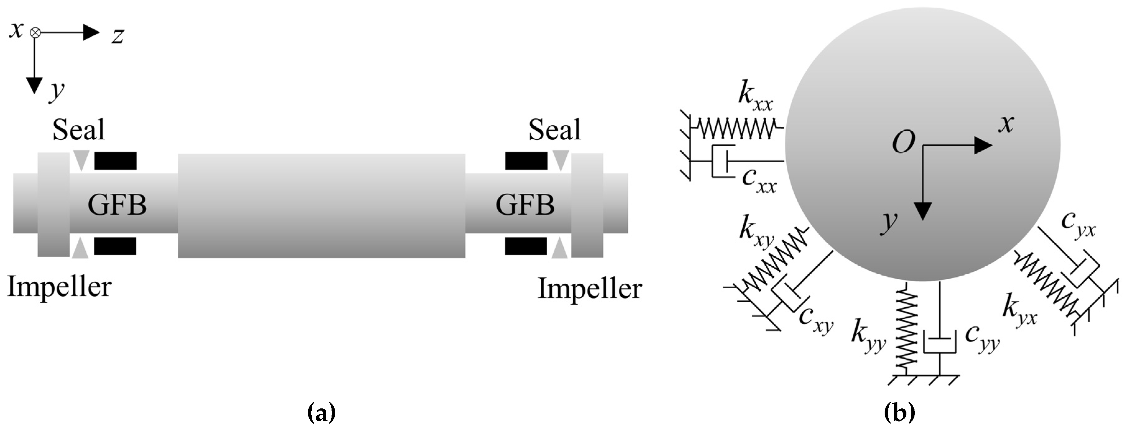
A schematic of the rotor structure is shown in Figure 2. In this study, the GFB, labyrinth seal, and impeller are simplified as stiffness and damping coefficients at the corresponding nodes in the rotordynamic model, while a disk with the same mass and moment of inertia is added at the impeller. The force–displacement model of the GFB, labyrinth seal, and impeller on the rotor is expressed as
F x F y = k x x k x y k y x k y y X Y + c x x c x y c y x c y y X ˙ Y ˙
In this study, the rotor is modeled using beam units that take into account the shear force, and the gyroscopic effect of the rotor is considered. The rotordynamic model considering gyroscopic effects can be described as [7]
M U ¨ + ( ω G + C ) U ˙ + K U = Q
where M is the mass matrix; G is the gyro matrix; C is the damping matrix; K is the stiffness matrix; ω is the rotor angular velocity; U is the rotor nodal displacement vector; and Q is the nodal load vector.
For modal analysis, Equation (2) is rewritten in chi-square form:
M U ¨ + ( ω G + C ) U ˙ + K U = 0
In order to solve Equation (3), it is rewritten in the state space form:
V = U ˙ U , A = M 0 0 K , B = ω G + C K K 0
Substitute Equation (4) into Equation (3):
A V ˙ + B V = 0
Let the solution of Equation (5) be of the form
V = V 0 e v t
Substitution of Equation (6) into Equation (5):
( A v + B ) V 0 = 0
Convert Equation (7) to a standard eigenvalue problem:
( D v E ) V 0 = 0
where E is an identity matrix of the same size as D, and D can be expressed as
D = M 1 ( ω G + C ) M 1 K I 0
where I is an identity matrix of the same size as K.
The eigenfrequencies of the system and the corresponding eigenvectors can be found according to Equation (8).

2.2. Rotordynamic Coefficient Model

The rotordynamic coefficient model contains a GFB model, a labyrinth seal model, and a centrifugal impeller model.

2.2.1. GFB Model

In the field of thin-film lubrication, the use of the Reynolds equation instead of the N-S equation is considered valid and sufficiently accurate. The Reynolds equation for an isothermal compressible fluid in a cylindrical coordinate system can be expressed as [43]
θ p ¯ H ¯ 3 p ¯ θ + z ¯ p ¯ H ¯ 3 p ¯ z ¯ = Λ ( p ¯ H ¯ ) θ + 2 Λ γ ( p ¯ H ¯ ) t ¯
The Reynolds equation has been transformed into a dimensionless form for ease of analysis, where dimensionless air film pressure p ¯ , dimensionless axial coordinate z ¯ , dimensionless air film height H ¯ , bearing number Λ , excitation frequency ratio γ , and dimensionless time t ¯ are expressed as
p ¯ = p p a , z ¯ = z R , H ¯ = H C , Λ = 6 μ 0 ω p a R C 2 , γ = ω e ω , t ¯ = ω e t
where p is the gas film pressure; pa is the reference pressure; z is the axial coordinate; R is the journal radius; H is the gas film thickness; C is the nominal clearance; μ0 is the gas dynamic viscosity; ωe is the excitation frequency; and t is time.
The air film thickness H can be further expanded and expressed as
H = C + e cos θ θ 0 + δ
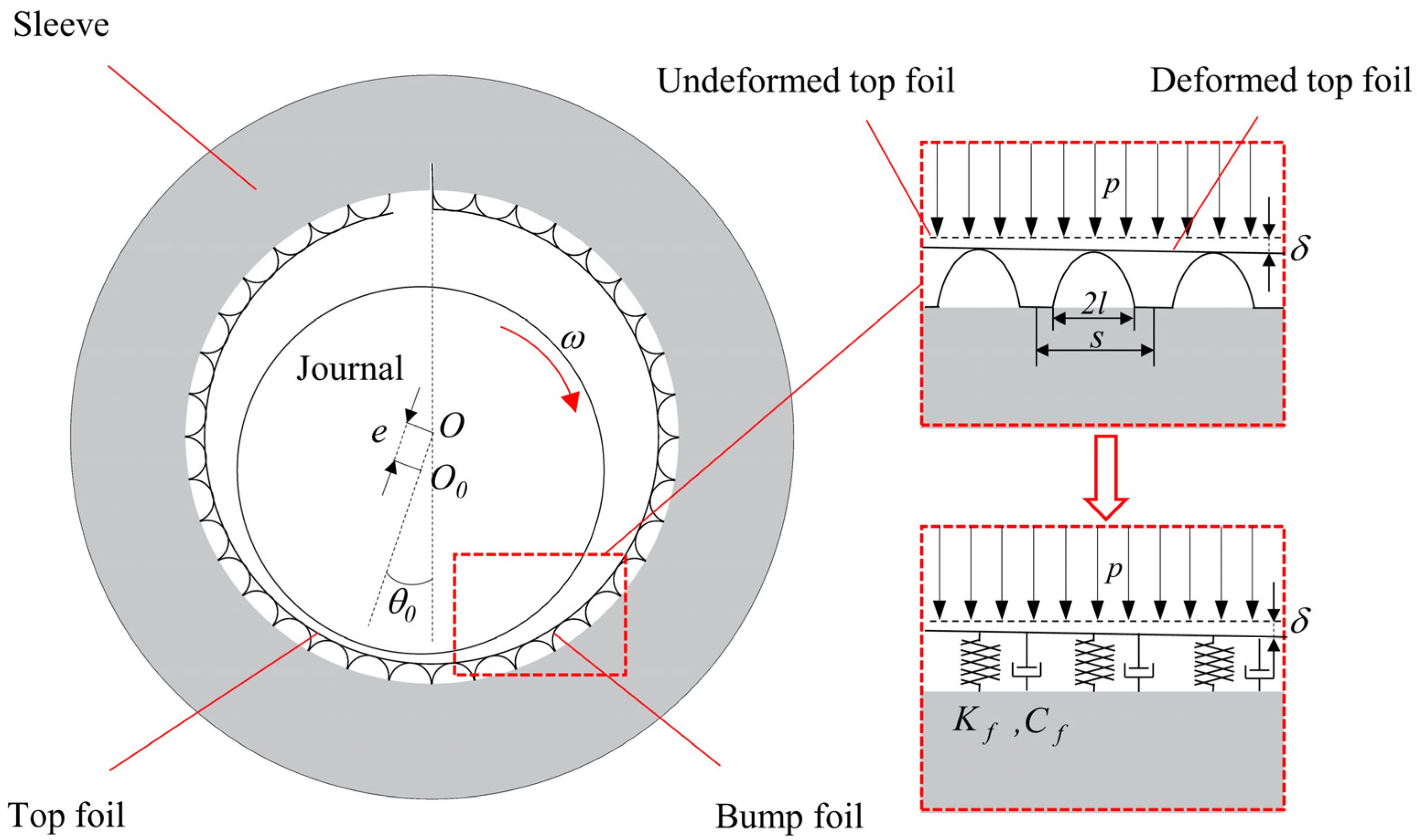
where e is the eccentricity, θ0 is the attitude angle, and δ is the top foil deformation, as shown in Figure 3.
The main difference in solving the Reynolds equation for the GFB compared to a rigid gas bearing is the need to consider the structural deformation of the flexible foil. In this study, the bump foil structure is equated to the spring stiffness coefficients and viscous damping coefficient, as shown in Figure 3, and this approach shows good agreement with the experimental results [20]. The relationship between the structural deformation of the foil and the gas film pressure after the equivalence is
p p a = K f δ + C f d δ d τ
where the foil structural stiffness coefficient Kf and the viscous damping coefficient Cf are expressed as
K f = k b + k t   at   δ ¯ 0 k t at   δ ¯ < 0 ,   C f = η γ k b   at   δ ¯ 0 0   at   δ ¯ < 0
where η is the structural loss factor; kb is the bump foil structural stiffness; and kt is the top foil structural stiffness. A deformation δ less than 0 represents the separation of the top foil from the bump foil. In this study, the top foil stiffness kt is modeled using the Mindlin plate that takes into account the shear force, and the bump foil stiffness kb is calculated by [44]
k b = 2 s l 3 ( 1 v b 2 ) E b t b 3
where s is the bump foil pitch; l is the bump convex half-length, as shown in Figure 3; vb is the Poisson’s ratio of the bump foil material; Eb is the elastic modulus of the bump foil material; and tb is the thickness of the bump foil.
The rotordynamic coefficients of the bearings are solved by the perturbation method proposed by Lund [8]. The process of solving the rotordynamic coefficients of GFBs using this method is explained in detail in reference [9]. One point that needs to be emphasized is that the model in this paper allows for regions where the pressure is less than zero.

2.2.2. Labyrinth Seal Model

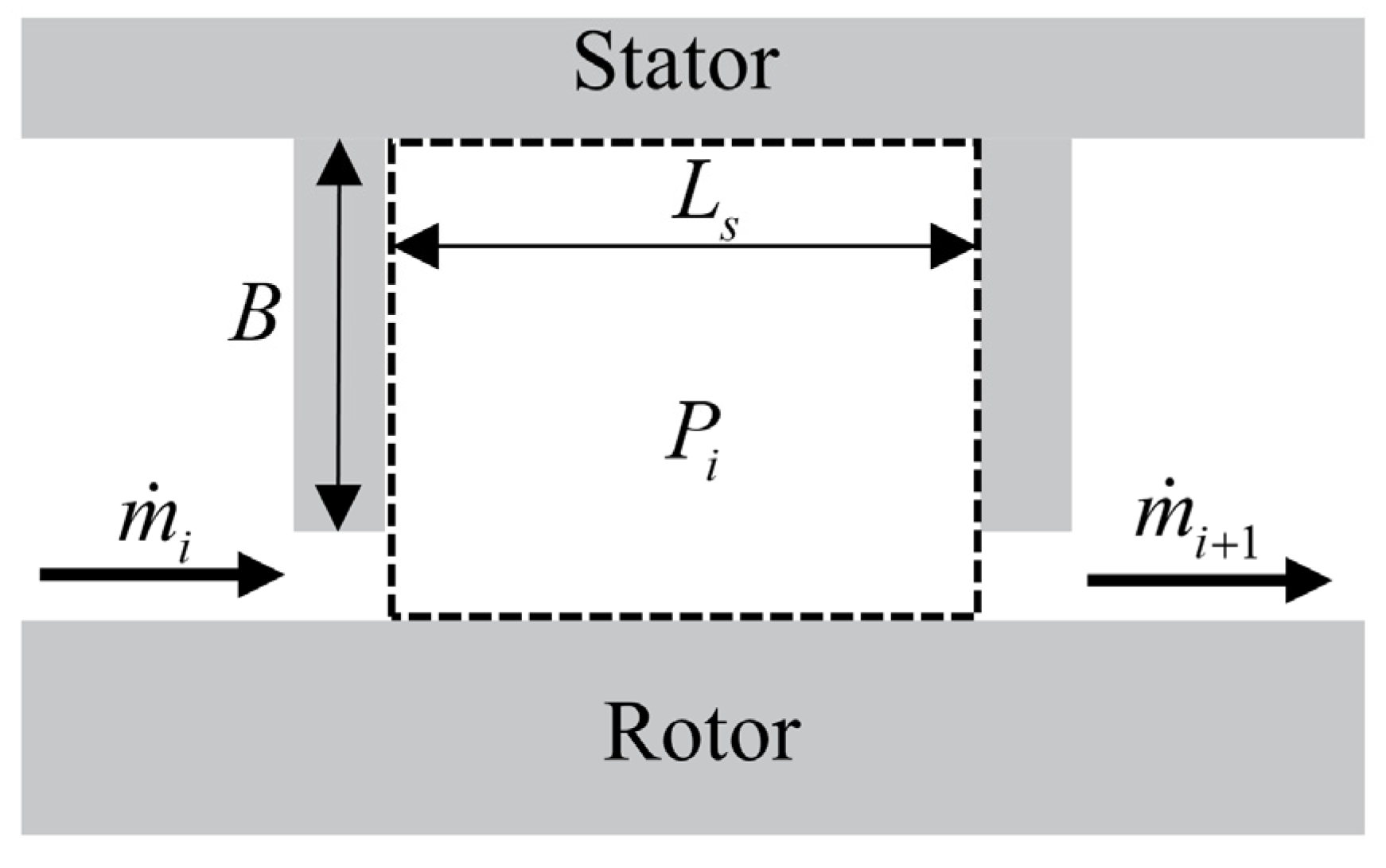
The control volume model of a cavity in a straight-through labyrinth seal is shown in Figure 4.
The continuity equation for the fluid in the cavity is [38]
t ρ A i + θ ρ V i A i R s + m ˙ i + 1 m ˙ i = 0
where A is the cross-sectional area of the cavity; ρ is the density of fluid; V is the circumferential mean flow velocity; Rs is the seal radius; m ˙ is the fluid leakage mass of each cavity, as determined by the Neumann equation [45]; and i is the sealing cavity number.
The momentum equation for the fluid in the cavity is given by
ρ V i A i t + 2 ρ V i A i R s V i θ + ρ V i 2 R s A i θ + V i A i R s ρ θ + m ˙ i + 1 V i m ˙ i V i 1 = A i R s P i θ + τ r L s τ s ( 2 B + L s )
where P is the gas pressure; Ls is the pitch of the labyrinth seal strips; B is the height of the labyrinth seal strip; and τ r and τ s are the shear stresses on the rotor and stator surfaces, determined by the Blasius equation [46].
Similar to the solution of the rotordynamic coefficients of GFB, the rotordynamic coefficients of labyrinth seals can be solved by the perturbation method using the perturbation parameter ε = e / C .

2.2.3. Centrifugal Impeller Model

The Wachel equation [33,34] has been verified by a large number of practices, has been listed by the American Petroleum Institute (API) as the standard calculation method in the stability calculation process of centrifugal compressors [47], and is applicable to most compressors [30]. In this study, the Wachel equation is used to calculate the aerodynamic cross-coupling stiffness of the impeller, and the rest of the rotordynamic coefficients are set to 0. The Wachel equation gives the aerodynamic cross-coupling stiffness of a centrifugal compressor impeller as follows:
k x y = k y x = β M W P W D h ω ( ρ o u t ρ i n )
where β is the cross-coupling constant; MW is the molecular weight of the gas; PW is the rated power per impeller; D is the impeller diameter; h is the diffuser width; ρout is the density of the gas discharged at the outlet; and ρin is the density of the gas drawn in.

3. Model Validation

3.1. Validation of GFB Gas–Elastic Coupling Model

We used publicly available test data [48] to validate our gas–elastic coupling model. The parameters of the tested GFB are shown in Table 1, and the unit area stiffness of the test bump foil was calculated from Equation (15) to be 4.7 GN/m3.
In reference [48], actual bearing clearances were not reported. An empirical value of C0= 20 μm for bearing clearance was used in this study [49], which is approximately the same as the minimum air film thickness measured at zero static loads at 45,000 rpm and 30,000 rpm in reference [48].
Figure 5 depicts the minimum film thickness versus applied load at speeds equal to (a) 30,000 rpm, (b) 45,000 rpm, and (c) 60,000 rpm with respect to the bearing length at L/2 and at L, respectively. The computational results show that the computational result errors of the gas–elastic coupling model in this paper are similar to those of several mainstream models [49].
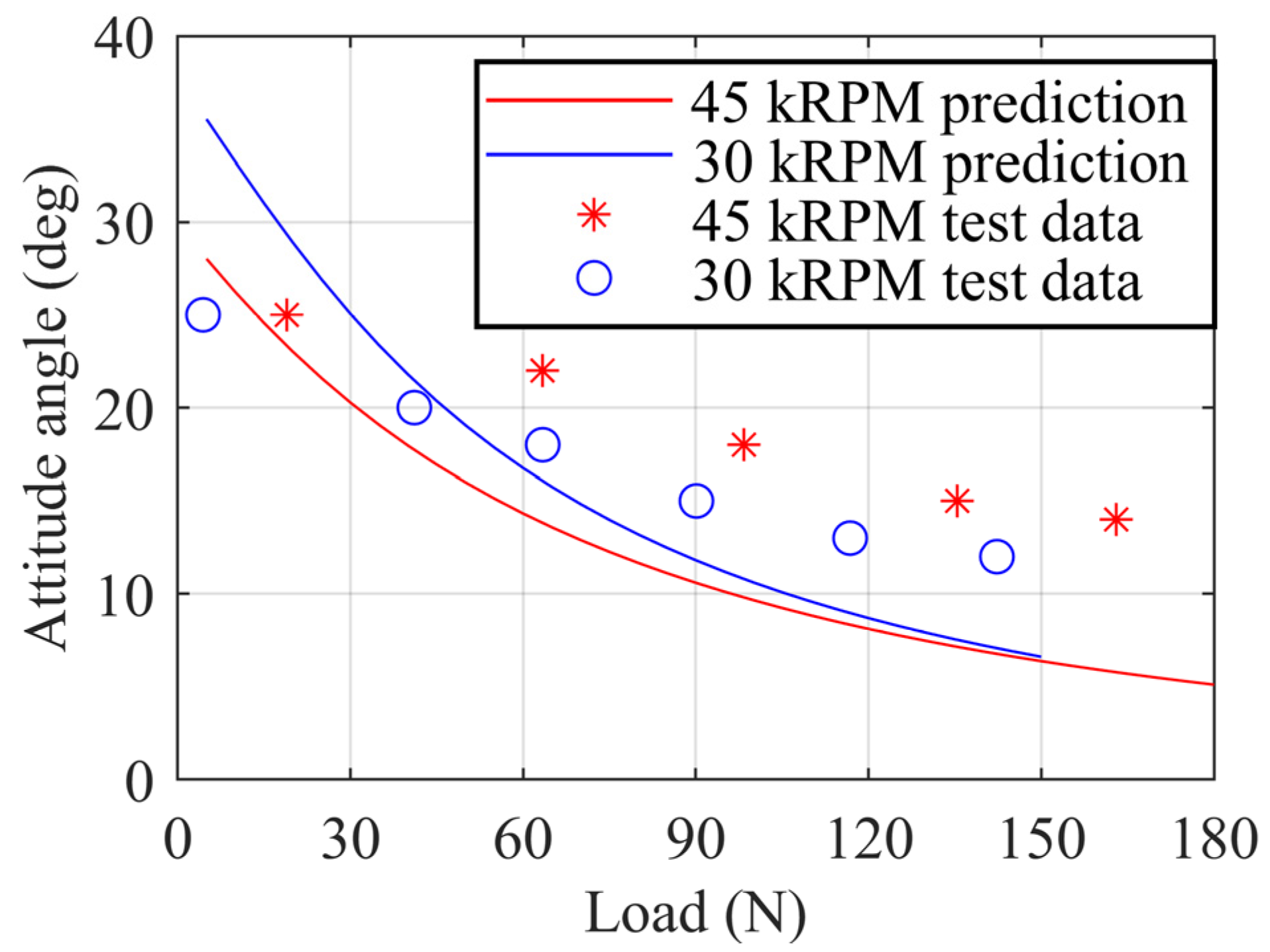
Figure 6 shows the attitude angle of the GFB versus the applied load at 30,000 rpm and 45,000 rpm. Similar to the error in the air film thickness, the error in the results of this paper’s model for the attitude angle is similar to the error in the results of several mainstream models [49]. It can be concluded that the gas–elastic coupling model in this paper has sufficient accuracy.

3.2. Validation of Critical Speed Calculation Model

In order to verify the accuracy of the proposed numerical model, this study uses a centrifugal compressor for fuel cell vehicles as a test object to validate the model. In general, there is a certain correlation between the dimensions of bearings and impellers and seals, and the centrifugal compressor for fuel cell vehicles used in this paper is commercially available, so it has a true relationship of the dimensional parameters between impellers, seals, and bearings, which avoids errors in conclusions caused by incorrect dimensional relationships between the components. The meshing for the FEM model and photographs of the tested compressor’s rotor are shown in Figure 7.
The parameters of the high-speed centrifugal compressor used for the test are shown in Table 2.
The calculations were started at 20,000 RPM, which is slightly above the lift-off speed of the GFB, and the results are shown in Figure 8, from which it can be seen that the rotor rotation modes are categorized into forward and backward rotations according to the magnitude of the amount of forward and backward excitation. In actual operation, the instability force always excites forward rotation [32], so the critical speed is considered to be the intersection of the excitation line and the forward rotation frequencies. The calculation results show that the first two order modes of the test object are rigid, and the critical speed of the rigid modes is below the lift-off speed; the third order mode is bending, and the critical speed of the bending mode is 124,980 rpm. In the logarithmic decrement plot, forward modes that may trigger instability are labeled in red and backward and mixed modes in black. From the logarithmic decrement, it can be seen that there is instability in the first forward mode with a mode frequency of about 116 Hz. However, the eigenfrequencies of unstable mode are much lower than the lift-off frequency (20,000/60 = 333 Hz) and lower than the half-speed whirl frequency at lift-off speed (up to 43% away from the half-speed whirl frequency 167 Hz). The third-order forward mode, on the other hand, is stable but has a small damping ratio, so the amplitude is likely to be greater than the GFB radial clearance. The root locus analysis shows the same results as the logarithmic decrement, with eigenvalues located to the right of the complex plane at low speeds. Therefore, we predict that the rotor vibration will increase with the rise in rotational speed and sharply increase to an extreme value near the bending critical speed of 124,980 rpm.
The critical speed is determined through a test that assesses the vibration amplitude of the rotor. The centrifugal compressor critical speed test bench, shown in Figure 9a, is equipped with an eddy current displacement sensor on the primary impeller side to measure the vibration displacement of the rotor. During the test, the rotor is gradually accelerated to a speed exceeding the calculated bending critical speed. Then, the amplitude change patterns tested by the eddy current displacement sensor as the speed increases can be observed and analyzed. In order to prevent the centrifugal compressor from surging, the test of the compressor was carried out at a high flow rate and low compression ratio. In order to avoid damage to the test object by resonance brought about by the close proximity to the critical speed, the whole test process was completed within a few seconds, and therefore the amplitude measured by the test may not reach the maximum amplitude at that speed.
Before the test, the eddy current displacement sensor needs to be calibrated, and the displacement measurement position needs to be detected for roundness. The displacement error obtained from the final test is the superposition of the sensor error and roundness error. The sensor calibration and roundness detection setup are shown in Figure 9b. Firstly, the digital micrometer is used to calibrate the eddy current displacement sensor, and the error of the eddy current displacement sensor after calibration is 1 um. Then, the eddy current displacement sensor after calibration is used to detect the roundness of the measured position, and the difference between the maximum value and the minimum value of the roundness of the measured position is 2 um, so the final displacement error can be considered to be 1 + 2 = 3 um.
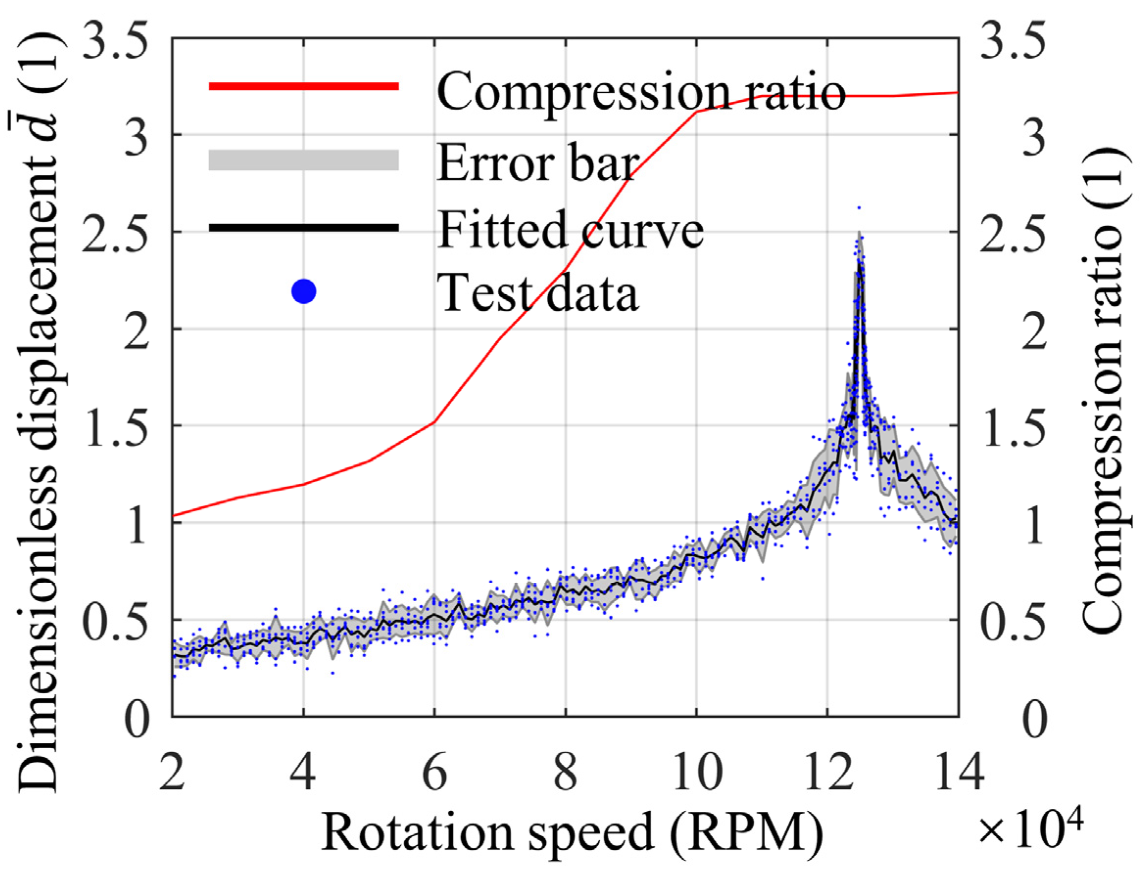
The experimental results are shown in Figure 10. The dimensionless displacement d ¯ = d / c , where d is the amplitude measured by the eddy current displacement sensor. As the compressor speed approaches the predicted critical speed, a notable increase in amplitude is observed, reaching its peak at 124,800 RPM. The deviation between this experimental finding and the model calculation is less than 1%, indicating high accuracy in the model’s predictions. During the test, the measured vibration amplitude was much larger than the nominal clearance, presumably caused by the rotor hitting the foil directly.

4. Results and Discussion

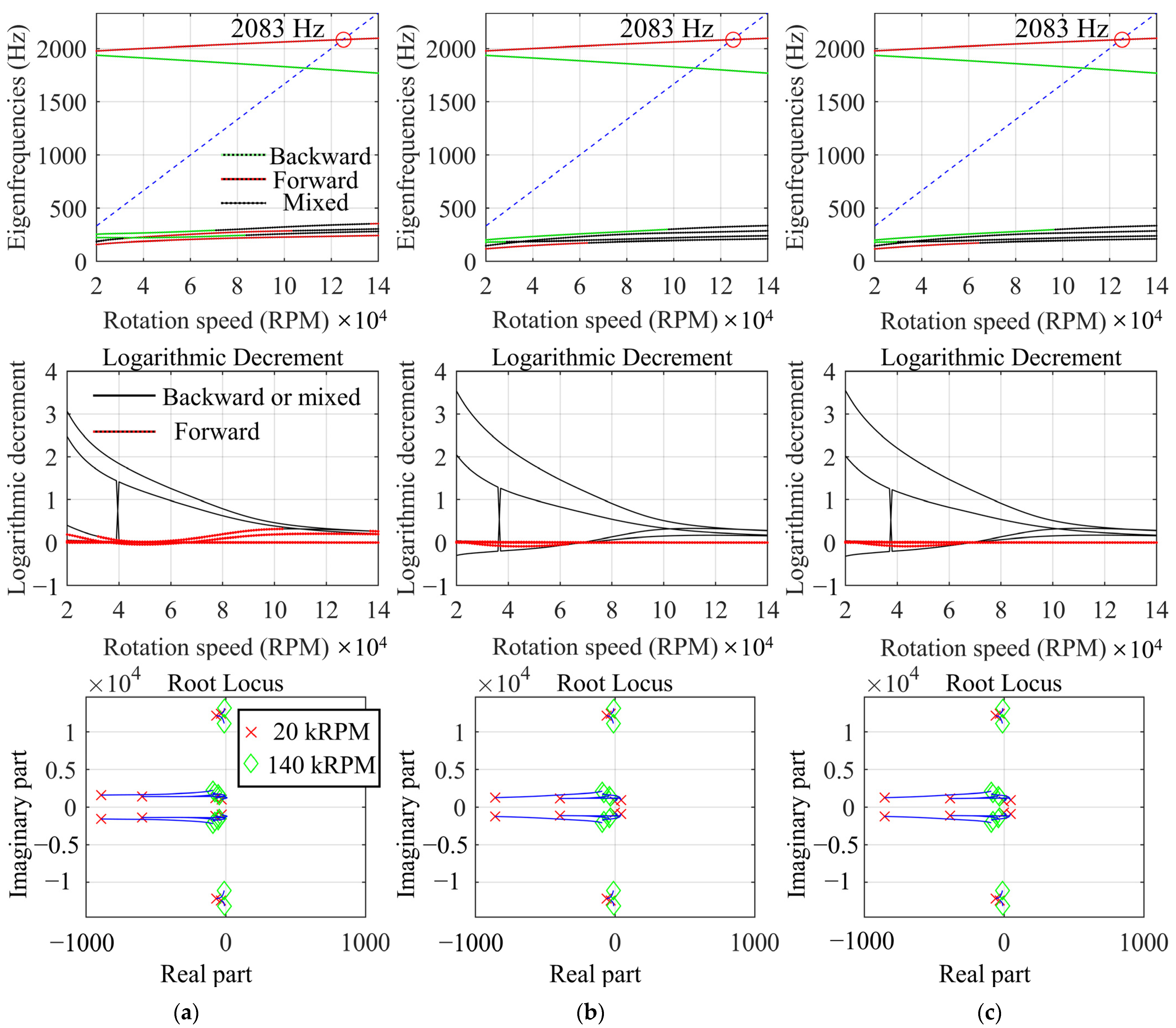
In this section, the effects of GFBs, impellers, and labyrinth seals on the critical speed are investigated separately. Firstly, we conduct critical speed calculations under different conditions: without considering the impeller aerodynamic forces, without considering the labyrinth seal aerodynamic forces, and without considering both. The results are presented in Figure 11. It can be seen that the calculated critical speeds do not change regardless of whether the impellers and labyrinth seals’ aerodynamic forces are considered or not, and the calculated eigenfrequencies change only slightly in the rigid modes at low speeds.
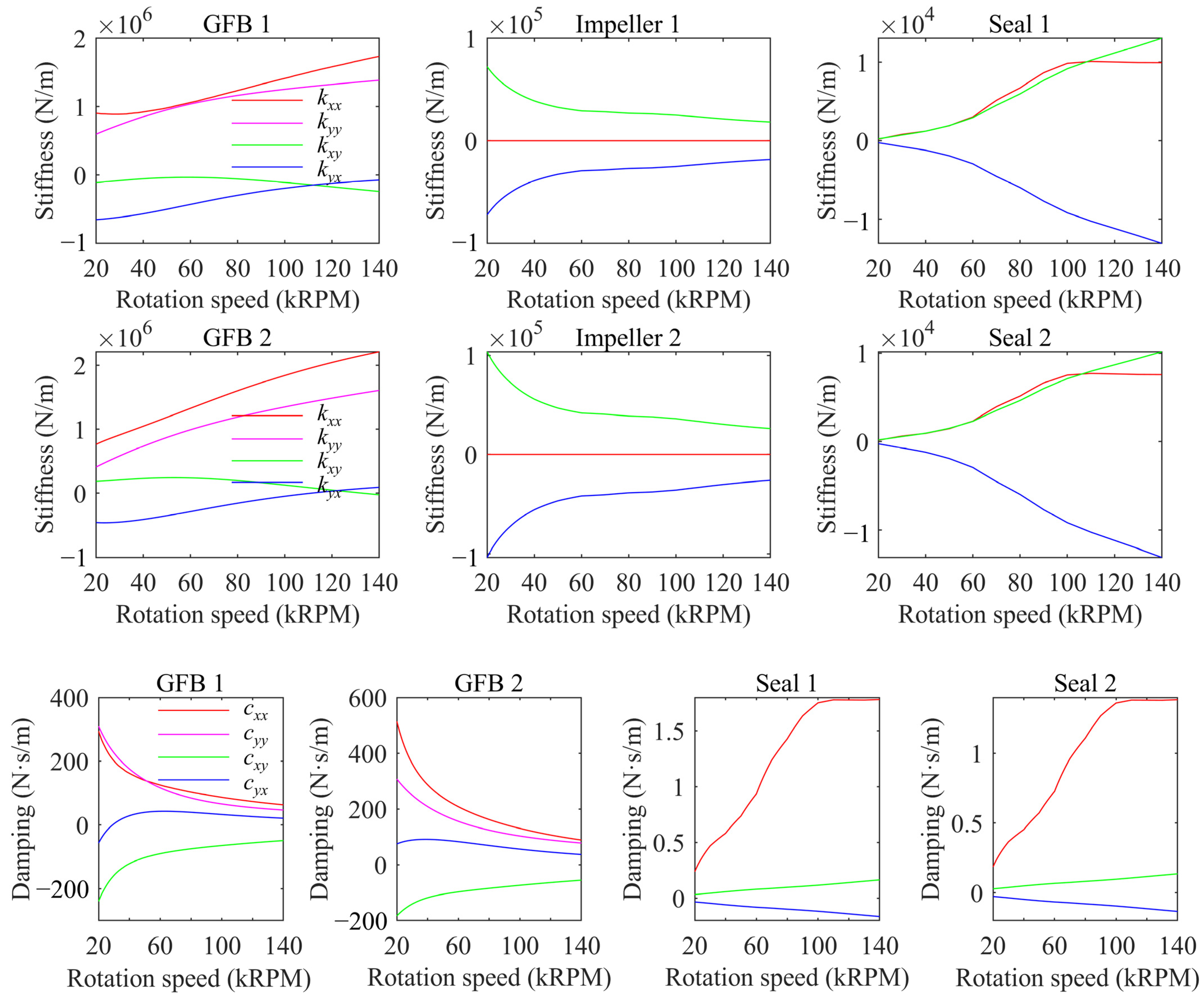
The reason for this phenomenon is due to the difference in the rotordynamic coefficients brought about by the various components, the rotordynamic coefficients of which are shown in Figure 12. It can be seen that the labyrinth seal has the smallest stiffness coefficients, followed by the impeller, while the GFBs exhibit the largest stiffness coefficients, with an order of magnitude difference between each of them. Consequently, the critical speed of the compressor is dominated by the GFBs with the largest stiffness coefficients. For damping, the difference is even greater. The damping of GFBs is hundreds of times greater than the damping of a seal. Based on this observation, it is reasonable to assume that, on the scale of centrifugal compressors for fuel cell vehicles, disregarding the impellers and labyrinth seals in critical speed calculations is acceptable.
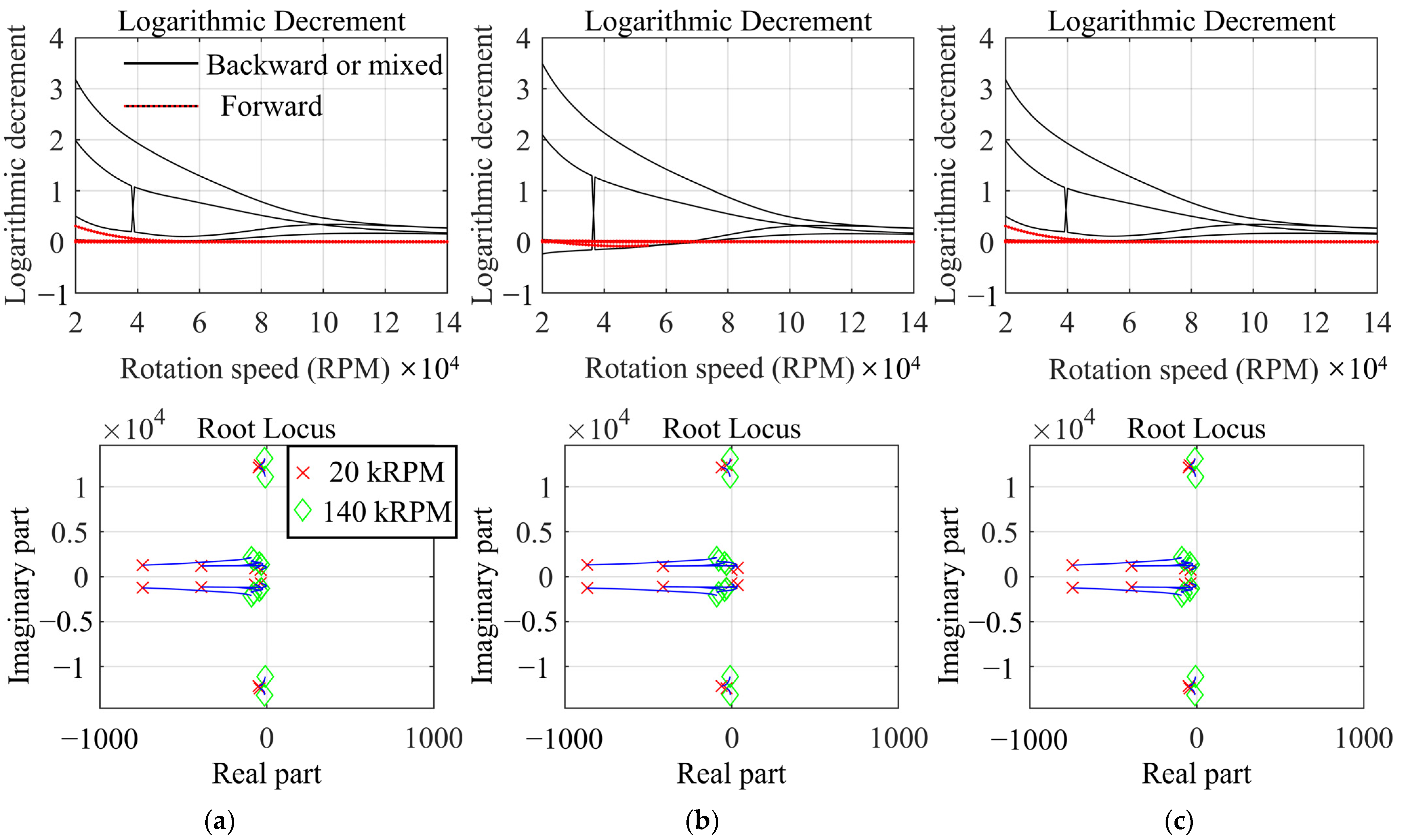
Figure 13 illustrates the modal stability when different components are included. Comparative analysis reveals that the cross-coupled stiffness of the impeller is responsible for the mode instability at low speeds. The stiffness variation curve of the impeller shows that its cross-coupling stiffness is in the same order of magnitude as the GFB at low speeds, while it decreases rapidly between 20,000 and 60,000 rpm, which coincides with the speed interval of mode instability at low speeds.
The structural stiffness of bump foils significantly influences the dynamic characteristics of GFBs and distinguishes them from rigid gas bearings. However, incorporating this flexible feature would substantially increase computational complexity. In order to determine the critical speed difference between GFBs with different bump foil structural stiffnesses, the critical speeds of GFBs with different bump foil structural stiffnesses are investigated. The bump foil structural stiffnesses 1.75 × 10⁹, 1.75 × 10¹⁰, and 1.75 × 10¹¹ and rigid gas bearings were selected for comparison, where the results for the bump foil structural stiffness of 1.75 × 10¹⁰ were presented in the previous section. It should be noted that the GFB with high bump foil structural stiffness still differs from the gas bearing with a rigid inner surface due to the fact that the top foil of the GFB can realize separation from the bump foil and thus deform inwardly in a concave manner at lower than ambient pressure.
Figure 14 shows the rotordynamic coefficients for different bump foil structural stiffness. It can be found that after the bump foil structural stiffness reaches 1.75 × 10¹⁰, the stiffness coefficients of the GFBs exhibit very slight changes with further increases in bump foil structural stiffness, almost the same as the results of the rigid gas bearing.
Figure 15 shows the calculation results of the critical speed change with bump foil structural stiffness. The critical speeds remain constant across the bump foil structural stiffness range of 1.75 × 10⁹ to 1.75 × 10¹¹ and are consistent with the rigid gas bearing. Moreover, the eigenfrequencies of different bump foil structural stiffnesses and rigid gas bearings only exhibit negligible differences in the rigid modes. Based on these observations, it is reasonable to simplify the GFBs to rigid gas bearings when calculating the critical speed.
In terms of stability, the bump foil structural stiffness of 1.75×10⁹ has a smaller unstable speed interval. However, as stated before, this mode has difficulty triggering instability due to the low eigenfrequencies.
Summarizing the above findings, it can be found that either ignoring the aerodynamic forces due to the impellers and seals or simplifying the GFBs to rigid bearings has little effect on the results of the critical speed (or eigenfrequencies) calculations. The stability results, on the other hand, are affected by the impeller and the bump foil structural stiffness, especially the stability of rigid modes at low frequencies; however, since the rigid modes have low frequencies, it is likely that they will not be excited in the operating range of the compressor. Therefore, we can first obtain the eigenfrequencies by simplifying the calculations, and if the eigenfrequencies of the rigid modes are lower than half of the lift-off speed, it can be considered that the compressor can operate stably between the lift-off speed and the bending critical speed.

5. Conclusions

Machines with specific applications, such as centrifugal compressors for fuel cell vehicles, usually have a similar design structure, which makes a joint multi-component analysis possible. By analyzing a commercially available centrifugal compressor for fuel cell vehicles, we comprehensively analyzed the factors influencing the critical speed. The numerical results obtained lead to the following conclusions:
1
A centrifugal compressor for fuel cell vehicles can be rationally designed to operate between speeds higher than the rigid mode and lower than the bending mode and to suppress the eigenfrequencies of the unstable rigid mode to less than half of the lift-off speed.
2
The instability of the low frequencies’ rigid mode comes from the cross-coupling stiffness of the impellers, and reducing the bump foil structure stiffness can suppress the instability to some extent.
3
The aerodynamic effects of the impellers and seals can be ignored when calculating the critical speed (or eigenfrequencies), and the GFBs can be reduced to a rigid gas bearing to reduce arithmetic costs.
4
If the rigid mode frequencies obtained by simplified calculations in the manner described in Conclusion 3 are less than half of the lift-off speed, no stability judgment is required, and the compressor can be considered to operate stably between the lift-off speed and the bending critical speed.
This paper fills a gap in the field of joint analysis of GFBs, impellers, and seals in the field of centrifugal compressors for fuel cell vehicles, and the conclusions drawn can be used to save computational costs in the design and validation of centrifugal compressors for fuel cell vehicles.

Author Contributions

Conceptualization, M.Y.; Methodology, M.Y. and X.L.; Software, M.Y. and C.Z.; Validation, M.Y.; Resources, X.L.; Data curation, Y.Z. and C.Z.; Writing—original draft, M.Y.; Writing—review & editing, M.Y. and X.L.; Supervision, X.L.. All authors have read and agreed to the published version of the manuscript.

Funding

This research did not receive any specific grant from funding agencies in the public, commercial, or not-for-profit sectors.

Data Availability Statement

Data are contained within the article.

Conflicts of Interest

The authors declare that they have no known competing financial interests or personal relationships that could have appeared to influence the work reported in this paper.

References

  1. Hu, D.; Yang, L.; Yi, F.; Hu, L.; Yang, Q.; Zhou, J. Optimization of speed response of super-high-speed electric air compressor for hydrogen fuel cell vehicle considering the transient current. Int. J. Hydrog. Energy 2021, 46, 27183–27192. [Google Scholar] [CrossRef]
  2. Kim, J.-H.; Kim, D.-M.; Jung, Y.-H.; Lim, M.-S. Design of Ultra-High-Speed Motor for FCEV Air Compressor Considering Mechanical Properties of Rotor Materials. IEEE Trans. Energy Convers. 2021, 36, 2850–2860. [Google Scholar] [CrossRef]
  3. Zhao, Y.; Liu, Y.; Liu, G.; Yang, Q.; Li, L.; Gao, Z. Air and hydrogen supply systems and equipment for PEM fuel cells: A review. Int. J. Green Energy 2022, 19, 331–348. [Google Scholar] [CrossRef]
  4. Chen, S.; Zuo, S.; Wu, Z.; Liu, C. Comprehensive vibro-acoustic characteristics and mathematical modeling of electric high-speed centrifugal compressor surge for fuel cell vehicles at various compressor speeds. Mech. Syst. Signal Process. 2022, 178, 109311. [Google Scholar] [CrossRef]
  5. Shi, T.; Chen, Q.; Peng, X.; Feng, J.; Guo, Y. Multi-objective optimization of the oil-free centrifugal air compressor in hydrogen fuel cell vehicles based on grey relational analysis. Int. J. Hydrog. Energy 2023, 48, 26341–26355. [Google Scholar] [CrossRef]
  6. Ying, M.; Liu, X.; Zhang, C.; Wang, X.; Liu, Y.; Zhang, Y. The Two-Pad: A Novel Gas Foil Bearing for Fuel Cell Vehicles. Int. J. Energy Res. 2023, 2023, 5521171. [Google Scholar] [CrossRef]
  7. Friswell, M.I.; Penny, J.E.T.; Garvey, S.D.; Lees, A.W. Dynamics of Rotating Machines; Cambridge University Press: Cambridge, UK, 2010. [Google Scholar] [CrossRef]
  8. Lund, J.W. Calculation of Stiffness and Damping Properties of Gas Bearings. J. Lubr. Technol. 1968, 90, 793–803. [Google Scholar] [CrossRef]
  9. Peng, J.-P.; Carpino, M. Calculation of Stiffness and Damping Coefficients for Elastically Supported Gas Foil Bearings. J. Tribol. 1993, 115, 20–27. [Google Scholar] [CrossRef]
  10. Peng, J.-P.; Carpino, M. Coulomb friction damping effects in elastically supported gas foil bearings. Tribol. Trans. 1994, 37, 91–98. [Google Scholar] [CrossRef]
  11. Carpino, M.; Talmage, G. Prediction of Rotor Dynamic Coefficients in Gas Lubricated Foil Journal Bearings with Corrugated Sub-Foils. Tribol. Trans. 2006, 49, 400–409. [Google Scholar] [CrossRef]
  12. Lee, N.S.; Choi, D.H.; Lee, Y.B.; Kim, T.H.; Kim, C.H. The influence of the slip flow on steady-state load capacity, stiffness and damping coefficients of elastically supported gas foil bearings. Tribol. Trans. 2002, 45, 478–484. [Google Scholar] [CrossRef]
  13. Kim, D. Parametric Studies on Static and Dynamic Performance of Air Foil Bearings with Different Top Foil Geometries and Bump Stiffness Distributions. J. Tribol. 2007, 129, 354–364. [Google Scholar] [CrossRef]
  14. Kim, T.; Andres, L. Heavily loaded gas foil bearings: A model anchored to test data. J. Eng. Gas Turbines Power-Trans. Asme 2008, 130. [Google Scholar] [CrossRef]
  15. Kim, T.; San Andres, L. Limits for high-speed operation of gas foil bearings. J. Tribol. Trans. Asme 2006, 128, 670–673. [Google Scholar] [CrossRef]
  16. Kim, T.H.; Andrés, L.S. Analysis of advanced gas foil bearings with piecewise linear elastic supports. Tribol. Int. 2007, 40, 1239–1245. [Google Scholar] [CrossRef]
  17. Larsen, J.S.; Hansen, A.J.; Santos, I.F. Experimental and theoretical analysis of a rigid rotor supported by air foil bearings. Mech. Ind. 2015, 16, 106. [Google Scholar] [CrossRef]
  18. von Osmanski, S.; Larsen, J.S.; Santos, I.F. The classical linearization technique’s validity for compliant bearings. In Mechanisms and Machine Science, Proceedings of the 10th International Conference on Rotor Dynamics–IFToMM, Rio de Janeiro, Brazil, 23–27 September 2018; Cavalca, K., Weber, H., Eds.; Springer: Cham, Switzerland, 2019; Volume 1, pp. 177–191. [Google Scholar]
  19. Bonello, P.; Pham, H.M. Nonlinear dynamic analysis of high speed oil-free turbomachinery with focus on stability and self-excited vibration. J. Tribol. 2014, 136, 41705. [Google Scholar] [CrossRef]
  20. Larsen, J.S.; Santos, I.F. On the nonlinear steady-state response of rigid rotors supported by air foil bearings-theory and experiments. J. Sound Vib. 2015, 346, 284–297. [Google Scholar] [CrossRef]
  21. Papafragkos, P.; Gavalas, I.; Raptopoulos, I.; Chasalevris, A. Optimizing energy dissipation in gas foil bearings to eliminate bifurcations of limit cycles in unbalanced rotor systems. Nonlinear Dyn. 2023, 111, 67–95. [Google Scholar] [CrossRef]
  22. Hoffmann, R.; Pronobis, T.; Liebich, R. Non-linear stability analysis of a modified gas foil bearing structure. In Mechanisms and Machine Science, Proceedings of the 9th IFToMM International Conference on Rotor Dynamics, Milan, Italy, 29 August–5 September 2015; Pennacchi, P., Ed.; Springer: Cham, Switzerland, 2015; pp. 1259–1276. [Google Scholar]
  23. Larsen, J.S.; Santos, I.F.; von Osmanski, S. Stability of rigid rotors supported by air foil bearings: Comparison of two fundamental approaches. J. Sound Vib. 2016, 381, 179–191. [Google Scholar] [CrossRef]
  24. Von Osmanski, S.; Larsen, J.S.; Santos, I.F. Multi-domain stability and modal analysis applied to Gas Foil Bearings: Three approaches. J. Sound Vib. 2020, 472, 115174. [Google Scholar] [CrossRef]
  25. Gupta, M.K.; Childs, D.W. Rotordynamic stability predictions for centrifugal compressors using a bulk-flow model to predict impeller shroud force and moment coefficients. J. Eng. Gas Turbines Power-Trans. Asme 2010, 132, 91402. [Google Scholar] [CrossRef]
  26. Zhang, D.; Lee, C.; Cave, M. A CFD study on the dynamic coefficients of labyrinth seals. In Turbo Expo: Power for Land, Sea, and Air; American Society of Mechanical Engineers: New York, NY, USA, 2012; Volume 44731, pp. 795–803. [Google Scholar]
  27. Ali, M.S.; Mortazavi, F.; Palazzolo, A. System Level Analysis of Compressor Eye-Labyrinth Seal Rotordynamic Forces: A Computational Fluid Dynamics Approach. In Turbo Expo: Power for Land, Sea, and Air; American Society of Mechanical Engineers: New York, NY, USA, 2021; Volume 85031, p. V09BT28A004. [Google Scholar]
  28. Song, J.; Kim, S.; Park, T.C.; Cha, B.J.; Lim, D.H.; Hong, J.S.; Lee, T.W.; Song, S.J. Non-Axisymmetric Flows and Rotordynamic Forces in an Eccentric Shrouded Centrifugal Compressor—Part 1: Measurement. J. Eng. Gas Turbines Power 2019, 141, 111014. [Google Scholar] [CrossRef]
  29. Song, J.; Song, S.J. Non-Axisymmetric Flows and Rotordynamic Forces in an Eccentric Shrouded Centrifugal Compressor—Part 2: Analysis. J. Eng. Gas Turbines Power 2019, 141, 111015. [Google Scholar] [CrossRef]
  30. San Andrés, L. A Review of Turbine and Compressor Aerodynamic Forces in Turbomachinery. Lubricants 2023, 11, 26. [Google Scholar] [CrossRef]
  31. Alford, J.S. Protecting Turbomachinery from Self-Excited Rotor Whirl. J. Eng. Power 1965, 87, 333–343. [Google Scholar] [CrossRef]
  32. Childs, D.W. Turbomachinery Rotordynamics with Case Studies; Minter Spring Publishing: New, York, NY, USA, 2013. [Google Scholar]
  33. Wachel, J.C.; Von Nimitz, W.W. Ensuring the Reliability of Offshore Gas Compression Systems. J. Pet. Technol. 1981, 33, 2252–2260. [Google Scholar] [CrossRef]
  34. Wachel, J.C. Rotordynamic instability field problems. In Proceedings of the NASA, Lewis Research Center Rotordyn, Instability Probl, in high-Performance Turbomachinery Workshop, San Antonio, TX, USA, 16–18 May 1982. [Google Scholar]
  35. Moore, J.J.; Ransom, D.L.; Viana, F. Rotordynamic Force Prediction of Centrifugal Compressor Impellers Using Computational Fluid Dynamics. In Turbo Expo: Power for Land, Sea, and Air; American Society of Mechanical Engineers: New York, NY, USA, 2007; Volume 47942, pp. 1023–1033. [Google Scholar]
  36. Moore, J.J.; Ransom, D.L. Refinement of Physics Based Approach Used in the Prediction of Impeller Rotordynamic Forces for Centrifugal Compressors. In Volume 5: Structures and Dynamics, Parts A and B; ASMEDC: Washington, DC, USA, 2008; pp. 1305–1309. [Google Scholar] [CrossRef]
  37. Iwatsubo, T. Evaluation of instability forces of labyrinth seals in turbines orcompressors. In Proceedings of the NASA. Lewis Res. Center Rotordyn. Instability Probl. in High-Performance Turbomachinery, Kobe, Japan, 12–14 May 1980; pp. 139–167. [Google Scholar]
  38. Childs, D.W.; Scharrer, J.K. An Iwatsubo-Based Solution for Labyrinth Seals: Comparison to Experimental Results. J. Eng. Gas Turbines Power 1986, 108, 325–331. [Google Scholar] [CrossRef]
  39. Scharrer, J.K. Theory Versus Experiment for the Rotordynamic Coefficients of Labyrinth Gas Seals: Part I—A Two Control Volume Model. J. Vib. Acoust. 1988, 110, 270–280. [Google Scholar] [CrossRef]
  40. Nordmann, R.; Weiser, P. Evaluation of Rotordynamic Coefficients of Look-through Labyrinths by Means of a Three Volume Bulk Flow Model. In Proceedings of the NASA Lewis Research Center, Rotordynamic Instability Problems in High-Performance Turbomachinery 1990. Available online: https://ntrs.nasa.gov/citations/19920005138 (accessed on 28 October 2023).
  41. Moore, J.J. Three-Dimensional CFD Rotordynamic Analysis of Gas Labyrinth Seals. J. Vib. Acoust. 2003, 125, 427–433. [Google Scholar] [CrossRef]
  42. Pugachev, A.O.; Kleinhans, U.; Gaszner, M. Prediction of Rotordynamic Coefficients for Short Labyrinth Gas Seals Using Computational Fluid Dynamics. J. Eng. Gas Turbines Power 2012, 134, 62501. [Google Scholar] [CrossRef]
  43. Hamrock, B.J.; Schmid, S.R.; Jacobson, B.O. Fundamentals of Fluid Film Lubrication; Marcel Dekker: New York, NY, USA, 2004. [Google Scholar]
  44. Heshmat, H.; Walowit, J.A.; Pinkus, O. Analysis of gas lubricated compliant thrust bearings. J. Tribol. 1983, 105, 638–646. [Google Scholar] [CrossRef]
  45. Neumann, K. Zur Frage der Verwendung von Durchblickdichtungen im Dampfturbinenbau. Maschinenbautechnik 1964, 13, 188–195. [Google Scholar]
  46. Blasius, H. Das Aehnlichkeitsgesetz bei Reibungsvorgängen in Flüssigkeiten. In Mitteilungen über Forschungsarbeiten auf dem Gebiete des Ingenieurwesens; Mitteilungen über Forschungsarbeiten auf dem Gebiete des Ingenieurwesens; Springer: Berlin/Heidelberg, Germany, 1913; Volume 131. [Google Scholar] [CrossRef]
  47. API 617; Axial and Centrifugal Compressors and Expander-Compressors for Petroleum, Chemical and gas Industry Services. Approved American National Standard: Washington, DC, USA, 2014.
  48. Ruscitto, D.; McCormick, J.; Gray, S. Hydrodynamic air lubricated compliant surface bearing for an automotive gas turbine engine. I. J. Bear. Perform. 1978, 7095892. [Google Scholar] [CrossRef]
  49. Andres, L.; Kim, T. Analysis of gas foil bearings integrating FE top foil models. Tribol. Int. 2009, 42, 111–120. [Google Scholar] [CrossRef]
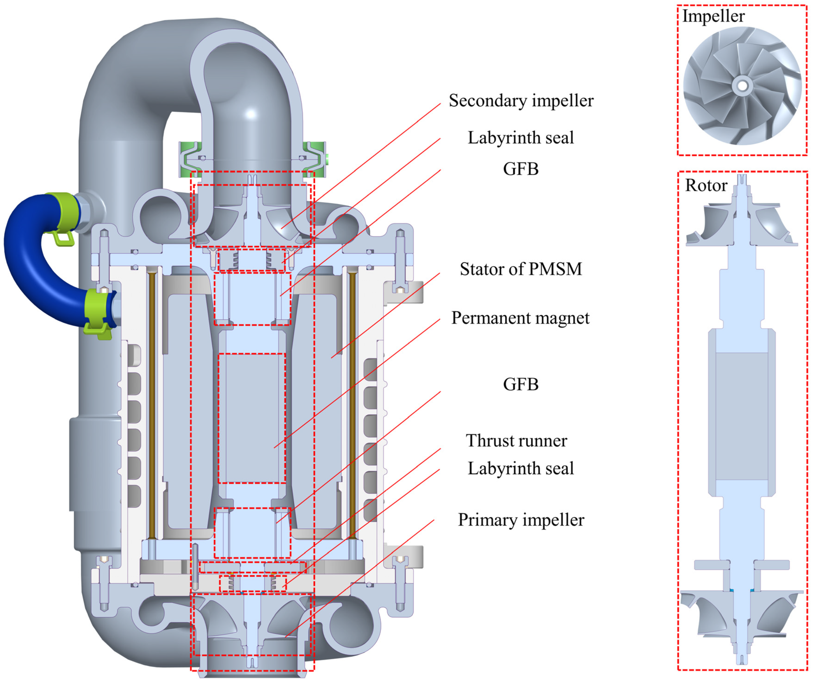
Figure 1. Structure of the centrifugal compressor for fuel cell vehicles.
Lubricants 11 00532 g001
Figure 2. Schematics of rotordynamic model: (a) simplified rotor model, (b) force–rotor displacement model.
Lubricants 11 00532 g002
Figure 3. Schematic of the GFB model.
Lubricants 11 00532 g003
Figure 4. Schematic of the cavity control volume.
Lubricants 11 00532 g004
Figure 5. Minimum film thickness versus static load. Predictions and test data [48]: (a) 30,000 rpm, (b) 45,000 rpm, (c) 60,000 rpm.
Lubricants 11 00532 g005
Figure 6. Attitude angle versus static load. Predictions and test data [48].
Lubricants 11 00532 g006
Figure 7. Structure of the tested rotor: (a) FEM model; (b) photo.
Lubricants 11 00532 g007
Figure 8. Modal calculation results: (a) mode frequencies; (b) mode shapes; (c) logarithmic decrement; (d) root locus.
Lubricants 11 00532 g008
Figure 9. Photo of test bench: (a) critical speed test; (b) calibration and roundness test.
Lubricants 11 00532 g009
Figure 10. Test results of displacement versus speed.
Lubricants 11 00532 g010
Figure 11. Critical speed calculation results: (a) ignore impellers’ aerodynamic forces; (b) ignore labyrinth seals’ aerodynamic forces; and (c) ignore both.
Lubricants 11 00532 g011
Figure 12. Rotordynamic coefficients of different components.
Lubricants 11 00532 g012
Figure 13. Stability results: (a) ignore impellers’ aerodynamic forces; (b) ignore labyrinth seals’ aerodynamic forces; and (c) ignore both.
Lubricants 11 00532 g013
Figure 14. Rotordynamic coefficient results of different bump foil structural stiffness.
Lubricants 11 00532 g014
Figure 15. Stability results of different bump foil structural stiffness: (a) bump foil structural stiffness = 1.75 × 10⁹; (b) bump foil structural stiffness = 1.75 × 10¹¹; (c) rigid.
Lubricants 11 00532 g015
Table 1. Parameters of the tested GFB from Ref. [48].
ParametersValue
Bearing inner radius, R019.05 mm
Bearing length, L038.1 mm
Radial clearance of GFB, C020 μm
Top foil thickness, ttop101.6 μm
Bump foil thickness, tbump101.6 μm
Bump pitch, s4.572 mm
Half bump length, l1.778 mm
Bump height, h0.508 mm
Bump foil Young’s modulus, Eb214 GPa
Bump foil Poisson’s ratio, νb0.29
Table 2. Parameters of the tested high-speed centrifugal compressor.
ParametersValue
Compressor rated power, PW30 Kw
Rated speed, Ow100,000 rpm
Mass of rotor, m1426 g
Bearing inner radius, R113 mm
Bearing length, L126 mm
Radial clearance of GFB, C130 µm
Bump foil structural stiffness, kb1.745 × 1010 N/m3
Top foil thickness, ttop0.124 mm
Maximum compression ratio, ρout/ρin3.97
Maximum mass flow, mf0.19 kg/s
Primary impeller diameter, D172 mm
Secondary impeller diameter, D268 mm
Mass of primary impeller, m175 g
Mass of secondary impeller, m253 g
Primary impeller diffuser width, h14.2 mm
Secondary impeller diffuser width, h23.1mm
Labyrinth seal clearance, Cs0.25 mm
Primary labyrinth seal radius, Rs110 mm
Secondary labyrinth seal radius, Rs28.5 mm
Height of labyrinth seal strip, B2.25 mm
Pitch of seal strips, Ls1.5 mm
Number of cavities, NC3
Disclaimer/Publisher’s Note: The statements, opinions and data contained in all publications are solely those of the individual author(s) and contributor(s) and not of MDPI and/or the editor(s). MDPI and/or the editor(s) disclaim responsibility for any injury to people or property resulting from any ideas, methods, instructions or products referred to in the content.