Article

Static and Dynamic Performances of Novel Aerostatic Bearings with Primary and Secondary Orifice Restrictors

1
The State Key Laboratory of Refractories and Metallurgy, Wuhan University of Science and Technology, Wuhan 430081, China
2
Key Laboratory of Metallurgical Equipment and Control Technology of Ministry of Education, Wuhan University of Science and Technology, Wuhan 430081, China
3
Hubei Key Laboratory of Mechanical Transmission and Manufacturing Engineering, Wuhan University of Science and Technology, Wuhan 430081, China
*
Authors to whom correspondence should be addressed.
Lubricants 2023, 11(12), 518; https://doi.org/10.3390/lubricants11120518
Submission received: 31 October 2023 / Revised: 2 December 2023 / Accepted: 6 December 2023 / Published: 8 December 2023

Abstract

:
Aerostatic bearings are crucial support components in ultra−precision manufacturing equipment. However, improvements in the load−carrying capability (LCC) of aerostatic bearings often lead to higher intensity nano−vibrations. This paper introduces a novel primary and secondary orifice restrictor (PSOR) designed to simultaneously enhance the LCC and mitigate nano−vibrations in aerostatic bearings. The static performance of complex turbulent flows occurring within the chamber of aerostatic bearings with PSORs was investigated. The dynamic performance of the turbulent flows was analyzed through 3D transient numerical simulation using the large eddy simulation method. The LCC and nano−vibration acceleration were measured experimentally, and the results indicated that the design of the secondary orifice diameter could enhance LCC and mitigate nano−vibrations, consistent with theoretical predictions. The accuracy of the proposed model was validated, confirming the effectiveness of PSOR. In the experiments, an aerostatic bearing with a secondary orifice diameter of 0.1 mm exhibited the lowest LCC and largest nano−vibration. Conversely, an aerostatic bearing with a secondary orifice diameter of 0.26 mm exhibited the highest LCC and weakest nano−vibration. This study provides insights into the formation mechanism of turbulent vortex and interaction mechanism among the primary orifice and secondary orifices in aerostatic bearings with a PSOR.

1. Introduction

Aerostatic bearings are extensively used in high−precision machining and ultra−precision machining owing to their remarkable attributes, including near−zero friction, high speed, and exceptional accuracy [1,2,3,4]. However, designing nano−positioning devices with high positional accuracy is challenging because of inherent nano−vibrations induced by turbulent vortices [5,6,7]. Operational conditions and structural parameters, such as film thickness, supply pressure, and restrictor dimensions, influence the dynamic behavior of aerostatic bearings. Therefore, several studies have focused on optimizing restrictor designs to mitigate nano−vibrations in aerostatic bearings.
Numerous researchers have investigated the characteristics of aerostatic bearings equipped with various types of restrictors, encompassing orifice, porous, and slot configurations [8,9,10]. Among these, the restrictors employing orifice−type designs with a chamber are the most extensively use in aerostatic bearings. Studies have primarily focused on attributes such as load−carrying capacity (LCC), stiffness, and pressure distribution [11,12,13]. Boffey et al. [14,15] examined the impact of recess restrictors on static performance, and Chen et al. [16] proposed a reliable mathematical model to calculate the stiffness of journal bearings with different restrictor designs and validated it through experiments. Chen and He [17] performed numerical simulations of the dynamic performance of aerostatic thrust bearings with various recess shapes using computational fluid dynamics (CFD) software Fluent, revealing that the LCC of aerostatic bearings with a rectangular recess is the highest. Li et al. [18] comprehensively analyzed the effects of pocketed orifice−type restrictors on aerostatic bearing performance using CFD software Fluent and through experiments, focusing on their relationships with restrictor structural parameters. However, while the chamber in the orifice−type aerostatic bearing enhances static performance, it simultaneously exacerbates pressure fluctuations and self−excited vibrations, thereby limiting motion positioning accuracy. Therefore, numerous studies have examined the complexities of pressure fluctuations and turbulent vortices near outward orifices [19,20]. Fourka et al. [21] established a non−linear model based on the finite element method to analyze the stability of air thrust bearings, revealing that the linear analysis underestimates the stability threshold compared with their non−linear model. Kawai et al. [22] experimentally demonstrated that nano−vibrations of aerostatic bearings may be attributed to air turbulence. Yoshimura et al. [23] investigated the behaviors of aerostatic bearings featuring T−shaped grooves through CFD analysis and experiments, revealing a direct correlation between nano−vibrations and pressure fluctuations stemming from transient airflow patterns along the bearing edge. Chen et al. [24] solved the full Navier–Stokes equations for the steady compressible flows to investigate turbulent vortices in the chamber using CFD software Fluent. The results from both the computational and experimental results demonstrated a direct correlation between the vibration energy of the aerostatic bearing and the intensity of the turbulent vortex. Eleshaky [25] employed the CFD method to investigate the pressure depression phenomenon in aerostatic thrust bearings. Otsu et al. [26] explored the instability of aerostatic journal bearings equipped with compound restrictors through numerical simulations and experiments. Wang et al. [27] precisely evaluated the pressure fluctuation characteristics in pneumatic hammer through the empirical mode method and experiments. Their findings indicated that vortex phenomena near the orifice restrictor outlet can induce instability in aerostatic bearings, highlighting the correlation between instability and both turbulent vortices in the chamber and the restrictor’s structural parameters.
To prevent vortex generation and alleviate nano−vibrations, numerous scholars have comprehensively investigated the dynamic behaviors of aerostatic bearings, employing a combination of experimental and theoretical approaches. Aoyama et al. [28] investigated airflow characteristics and the mechanism of nano−vibrations in guideways equipped with aerostatic bearings through numerical and experimental methods. Ma et al. [29] employed the fourth−order Runge–Kutta method and finite element method to evaluate the dynamic performances of aerostatic thrust bearings with an array of damping orifices, which can effectively improve the stability of pneumatic hammers. Zhu et al. [30] explored pressure fluctuations and vortex shedding through the large eddy simulation (LES) method, demonstrating connections between pressure fluctuations and nano−vibrations in aerostatic bearings through simulations and experiments. Li et al. [31] revealed the mechanism of vortex generation using the CFD software Fluent, demonstrating the advantages of design optimization via simulation and experiment. Chen et al. [32] employed the LES method to investigate the transient flow characteristics of aerostatic bearings with an arrayed micro−orifice restrictor designed to inhibit vortex generation and mitigate nano−vibrations. Feng et al. [33] proposed 3−D printed orifice restrictors and analyzed their airflow characteristics within the recess by using the CFD software Fluent, demonstrating that aerostatic bearings with arc−orifice structures exhibited the smallest vortices in the recess by simulation and experiment. Yu et al. [34] employed the LES method to investigate the influence of a square micro−hole−arrayed restrictor on the dynamic behavior of these bearings. Both numerical simulation and experimental results indicated that the nano−vibrations of aerostatic thrust bearings can be effectively suppressed.
In summary, vortex formation must be addressed when designing orifice−type aerostatic bearings with chambers to effectively minimize nano−vibrations. In this study, considering the mechanism of vortex formation, we developed a novel multiple−orifice restrictor known as the primary and secondary orifices restrictor (PSOR), aimed at inhibiting turbulent vortex formation and enhancing both static and dynamic performance. Dynamic characteristics were examined through the LES method, and static and dynamic behaviors, including LCC and vibration acceleration were assessed using two experimental setups. Theoretical predictions were validated by comparing the experimental results with our theoretical results. This study offers a novel approach for enhancing LCC, suppressing vortex formation, and enhancing the stability of aerostatic bearings through the optimized design of the PSOR.

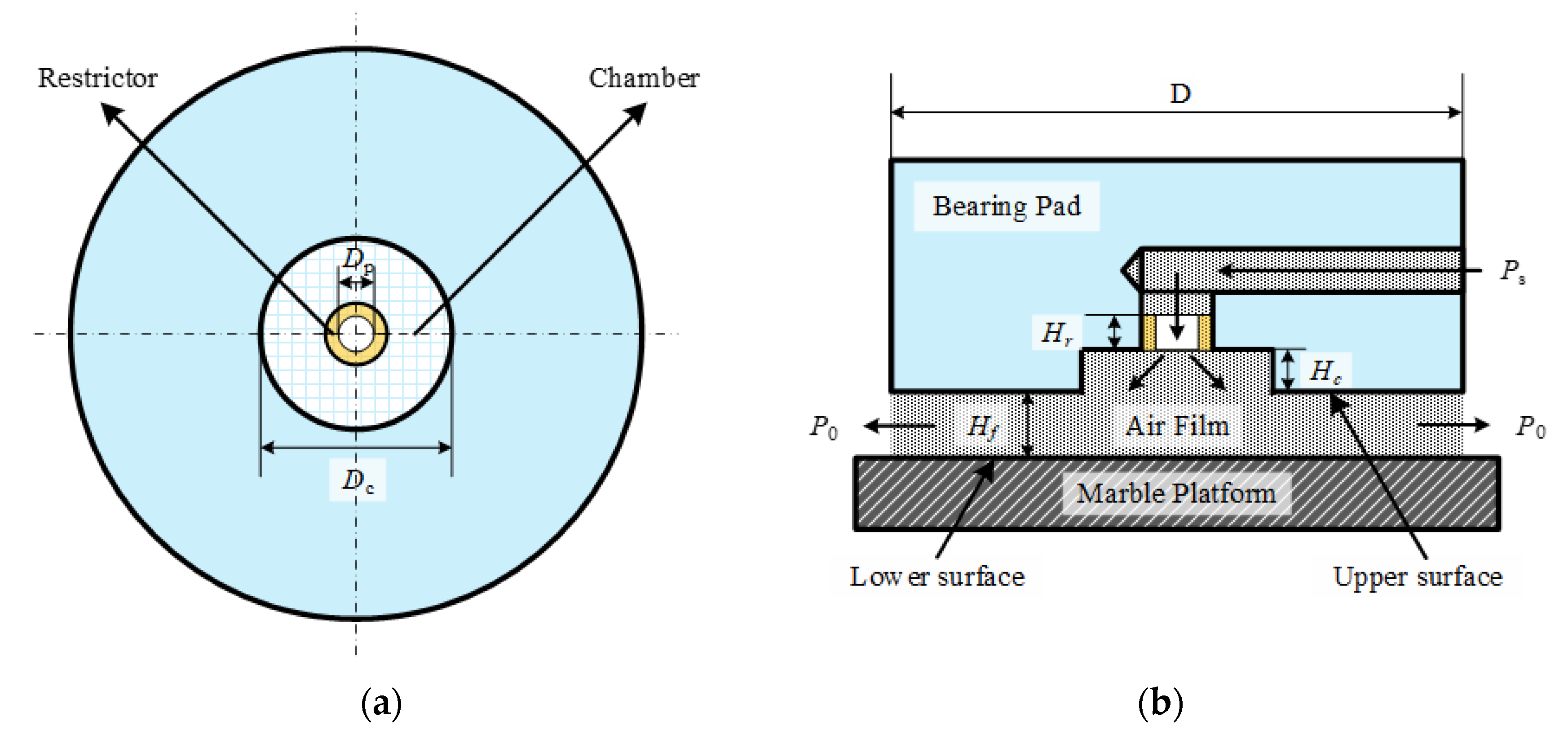
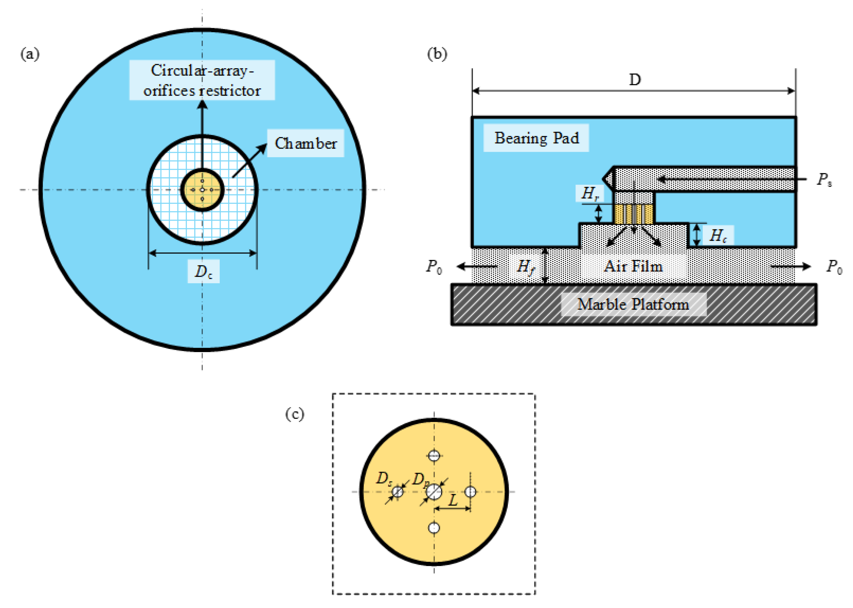
2. Aerostatic Bearings with Primary and Secondary Orifice Restrictors

Figure 1 illustrates the schematic diagram and operational principle of a single−orifice−type aerostatic bearing featuring a chamber. High−pressure air enters the chamber through the single−orifice restrictor (SOR), diffuses inside, and is subsequently released into the external atmosphere. Figure 2 depicts the pressure distribution and vorticity along the symmetry plane. Notably, turbulent vortices predominantly occur near the orifice outlet. Additionally, as the orifice diameter (i.e., the orifice area) decreases, the pressure distribution and vorticity within the chamber also gradually decrease. Therefore, varying the orifice diameter can modulate pressure distribution, influencing overall stability. Consequently, the orifice diameter, or the area through which air flows, notably impacts pressure distribution and the generation of turbulent vortices within the chamber.
Building on the aforementioned analysis, we introduce a novel aerostatic bearing with the primary and secondary orifice restrictor (PSOR), as depicted in Figure 3. The PSOR comprises one primary orifice and four secondary orifices. The four secondary orifices are symmetrically arranged circumferentially to ensure an even distribution of pressure in the chamber, preventing any imbalances in its gravitational center, as detailed in Table 1. The four secondary orifices facilitate the diffusion of the high−pressure gas into the chamber, resulting in a higher LCC of the aerostatic bearing. However, structural modifications to this novel type of aerostatic bearing complicate the lubrication mechanism, given the interplay and interdependence between adjacent orifices. Furthermore, the coupling effect between LCC and stability of aerostatic bearings is enhanced, necessitating a comprehensive investigation to ensure improvements in both LCC and stability.

3. Numerical Calculation Method

3.1. Large Eddy Simulation

The complex transient flow field characteristics of aerostatic bearings can be expressed using the Navier–Stokes equations. Li et al. [35] introduced a novel hyperbolic Navier–Stokes system (HNS) and a reconstructed discontinuous Galerkin (rDG) method for both steady and unsteady compressible viscous flows. As revealed by numerical simulations, the HNS + rDG approach is an attractive and viable alternative for solving the compressible Navier–Stokes equations. Kabir et al. demonstrated that the Reynolds Averaged Navier–Stokes (RANS) simulation method is suitable for investigating turbulence, but it may not be effective in accurately assessing the instantaneous complexities of turbulence [32]. In theory, direct numerical simulation (DNS) can precisely resolve the entire range of spatial and temporal scales of turbulence based on the Navier–Stokes equations without the need for any turbulence model. However, its computational scale is massive [30]. LESs can be used to perform a direct numerical simulation of vortices above the grid resolution scale in a flow field, encompassing the direct computation of large−scale turbulent vortices and the simulation of small−scale turbulent vortices. The accuracy and computational scale of LESs are between those of RANS and DNS, supporting its extensive use in the complex turbulence simulation of aerostatic bearings [30,36].
We applied filtering to the time−dependent Navier–Stokes equations using the governing equations. The filtering of the continuity and momentum equations [31,36] can be defined as follows:
ρ ¯ t + ( ρ ¯ u ˜ i ) x i = 0
( ρ ¯ u ˜ i ) t + ( ρ ¯ u ˜ i u ˜ j ) x j = σ ˜ i j x j p ¯ x i τ ˜ i j x j
The density−weighted filter is employed as the Favre filter, where the density ρ and pressure p are spatially filtered (denoted by “−”), while the velocity ui and uj are density−weighted (denoted by “~”). τ i j represents subgrid−scale (SGS) stress, which is modeled using an SGS model; σ ˜ i j representing the viscous stress tensor resulting from molecular viscosity is denoted as follows:
σ ˜ i j = μ ( u ˜ i x j + u ˜ j x i ) 2 3 μ δ i j u ˜ k x k
The compressible form of the subgrid−scale stress tensor is expressed as follows:
τ ˜ i j = ρ ¯ u i u j ˜ ρ ¯ u ˜ i u ˜ j
where
p ¯ = ρ ¯ R T ˜
Filtering the energy equation can be defined as follows:
ρ ¯ h ˜ s t + ρ ¯ u ˜ i h ˜ s x i ρ ¯ t u ˜ j ρ ¯ x i x i ( λ T ˜ x i ) = x j [ ρ ¯ ( u i h s ˜ u ˜ i h ˜ s ) ]
where h s and λ are the sensible enthalpy and thermal conductivity, respectively.
The compressible subgrid enthalpy flux term is defined as [30,37]:
ρ ¯ ( u i h s ˜ u ˜ i h ˜ s ) = μ S G S C P Pr S G S T ˜ x i
where μ S G S denotes subgrid viscosity and Pr S G S denotes the subgrid Prandtl number. In the present study, the wall−adapting local eddy−viscosity (WALE) model [30,37] was employed as the SGS model. The dynamic load−carrying capacity (DLCC), denoted as Fd, of the aerostatic bearing can be determined by integrating the pressure distribution on the wall surface. The dynamic load−carrying capacity can be defined as follows:
F d = 0 R 0 2 π ( p d p 0 ) r d r d θ
where pd represents transient pressure.
The standard deviation of the DLCC can be defined as follows:
σ f = i = 1 n ( F d i F m ) n
where Fdi represents the time−varying DLCC of the ith time step; Fm represents the LCC, which is the average value of DLCC; and n represents the number of iteration steps. The fluctuation force Ff = FdiFm represents the fluctuation in the DLCC.
Stiffness can be expressed as follows:
K = d F m d h

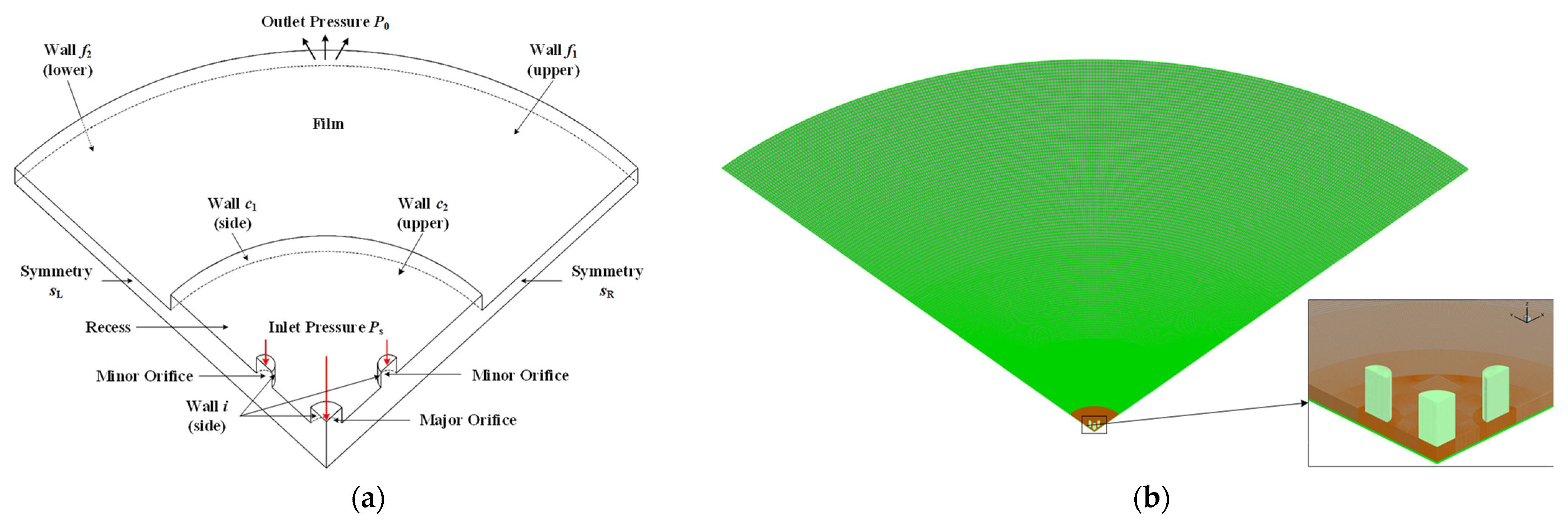
3.2. Grid Generation and Boundary Conditions

The turbulent vortex structures in the aerostatic bearing with the PSOR were investigated in a quarter of the computational domain to optimize computational efficiency. Figure 4b illustrates the use of a hexahedral semi−refined unstructured grid to ensure the precision and reliability of the simulation results by using Altair’s Hypermesh software. The Ansys CFD software Fluent was used for the simulations. Complex vortex structures in the chamber were investigated through the embedded large−eddy simulation (ELES) modeling technique. As illustrated in Figure 4a, a no−slip shear condition, no heat transfer conditions, and a perfectly smooth surface were applied as the boundary walls. Symmetrical boundaries were established on the two surfaces in the circumferential direction. Inlet pressure and outlet pressure were set at approximately 0.5 MPa and 0.1 MPa, respectively. The pressure−velocity coupling scheme employed the pressure−implicit with splitting of operators (PISO) algorithm [38]. To mitigate numerical dissipation, second−order upwind interpolation was applied to evaluate density, turbulent kinetic energy, and turbulent dissipation rate while employing bounded central differencing for momentum interpolation. Additionally, a second−order implicit scheme was used for transient simulation. The non−iterative time−advancement scheme [38] was employed to enhance numerical calculation efficiency and accuracy, with a time step size of Δt = 1 × 10⁻⁸ s, selected in accordance with the CFL condition uΔtx < 1.Table 2 lists the physical constants of air, assumed to adhere to the ideal gas law.

3.3. Mesh Grid Independent Analysis

Discrepancies attributable to the quantity and dimensions of grids can be mitigated based on the results of grid independence tests, which are considered complete when simulation results are no longer influenced by subsequent mesh refinement. The non−dimensional distance y+, which characterizes the resolution scale of the grids near the wall and is maintained at a value lower than 1, can be mathematically represented as y + = ρ τ w y / μ ) [30,34]. Here, τw represents the wall shear stress, and y denotes the length from the centroid of the initial layer grid near the wall region to its boundary. Table 3 presents the total numbers and volumes of grid elements within three distinct computational domains of the type A aerostatic bearing. However, the element count can be approximately equal only when the conditions remain constant despite the slight variations in the PSOR structures of aerostatic bearings. The mean force (Fm) and the standard deviation (σf) of the DLCC (Fd), as discussed in Section 4, are compared between the sparse−grid and refinement−grid cases, revealing that increasing the number of elements or implementing local grid refinement exerts minimal influence on the mean force or the standard deviation of the DLCC. The computational domain of aerostatic bearings with diverse PSOR configurations must be meshed with no fewer than two million elements to ensure both accuracy and computational efficiency.

4. Simulation Results and Discussion

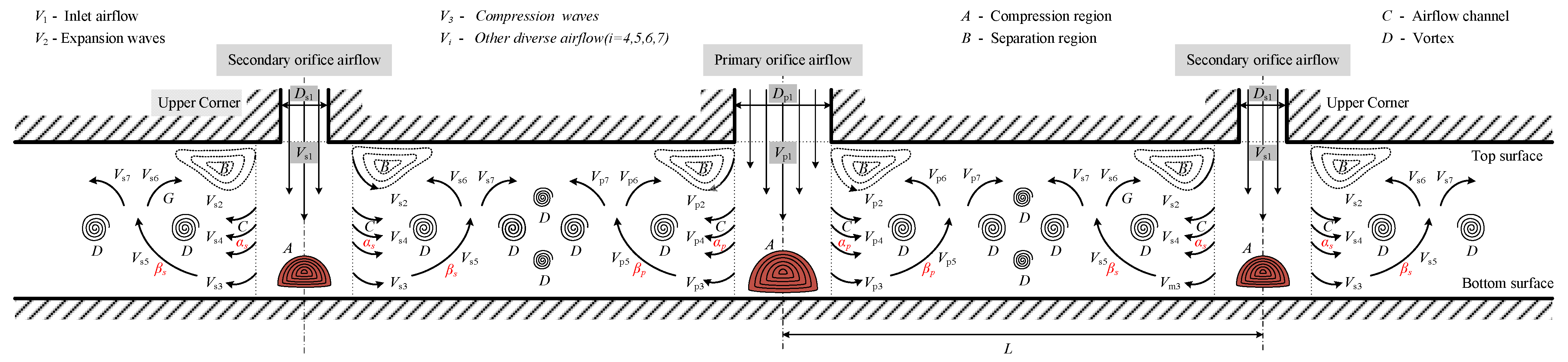
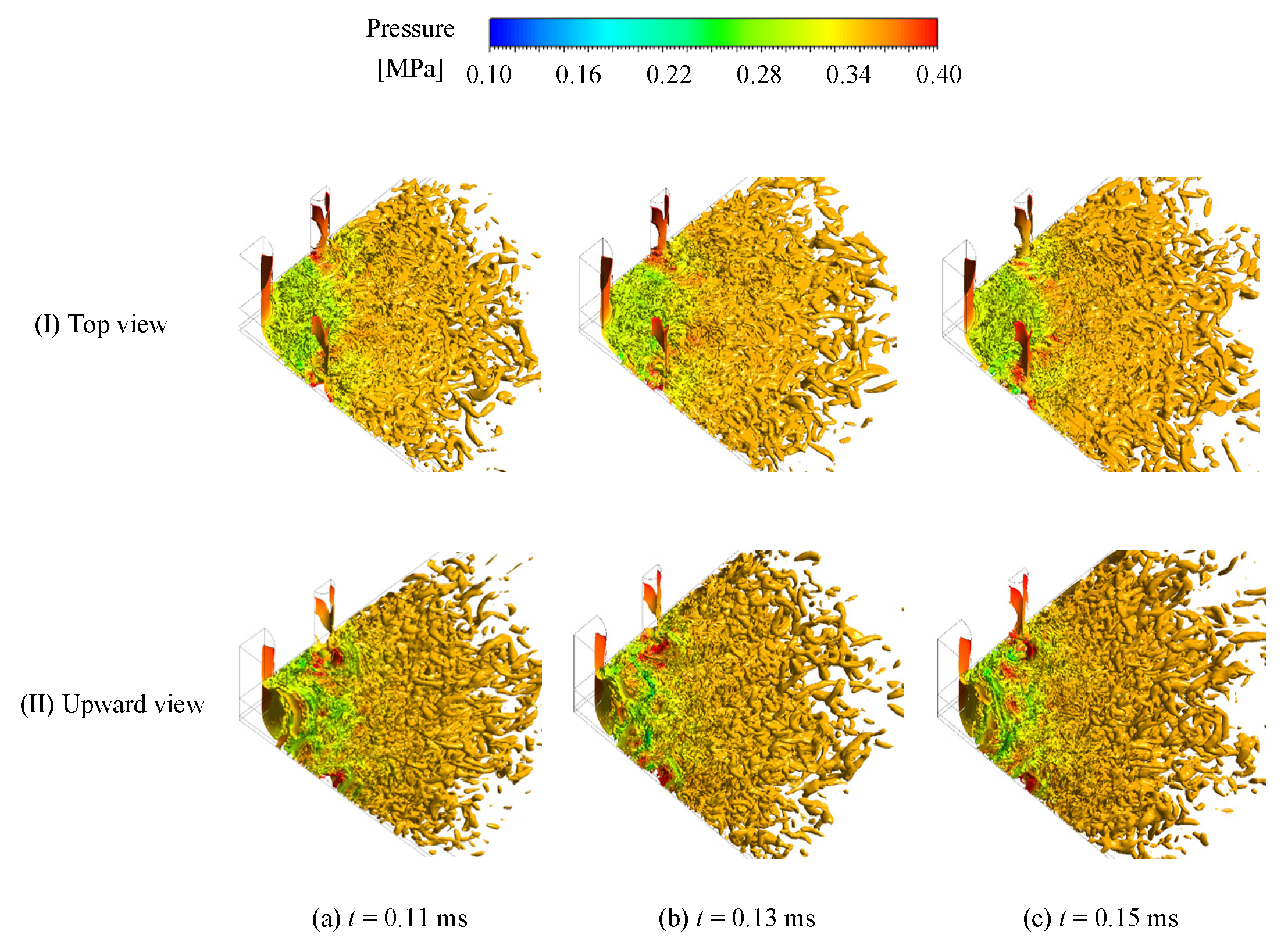
4.1. Turbulent Vortex Formation Mechanism

To illustrate the complex mechanisms governing the formation and evolution of turbulent vortices within a multi−orifice restrictor, we provide a detailed depiction of airflow near the outlet of any two adjacent orifices in the aerostatic bearing’s chamber, as depicted in Figure 5. As the high−speed, high−pressure airflow (A) exits through the orifice, it experiences a separation phenomenon when it encounters the top surface after the abrupt expansion of the airflow’s cross−sectional area. An airflow channel (C) with a deflection angle (α) emerges between the compression zone (A) and the separation zone (B). When airflow (V1) traverses the boundary layer between the separation zone (C) and the compression zone (B), an expansion wave (V2) and a compression wave (V3) are generated, respectively. Airflows (V3 and V4) progress towards the bottom surface through channel (C), and transform into airflow (V5) because of the splash effect. Upon colliding with the top surface, the airflow (V5) exhibits velocity separation, resulting in the formation of airflow (V6) and airflow (V7). Airflows originating from adjacent orifices exhibit opposing rotation directions and velocities, resulting in dynamic interactions that can generate intricate vortices. Different airflows with diverse flow directions and velocities engage in complex interactions with the surrounding air, leading to various turbulent vortices with distinct scales and intensities. Consequently, the interference of distinct airflows may induce complex and varying turbulent vortices. This continuous airflow initiates a perpetual cycle of vortex generation and dissipation, yielding a diverse array of turbulent vortices within the chamber.

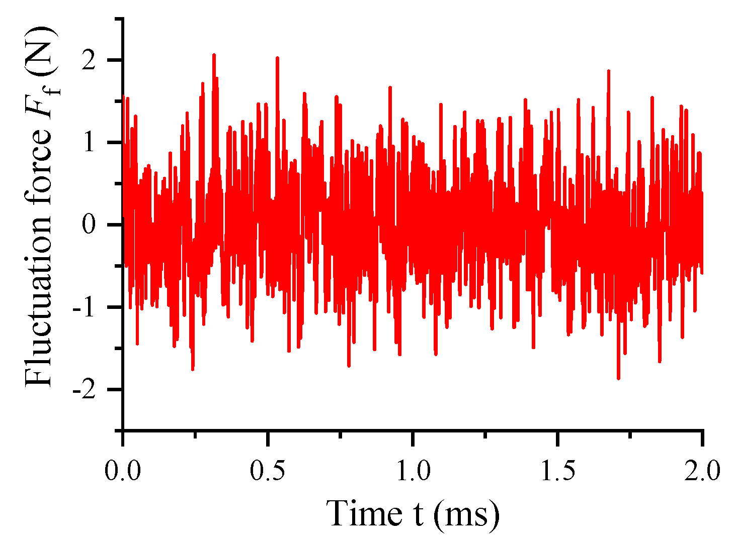
4.2. Transient Flow Behaviors

As illustrated in Figure 6 and Figure 7, numerous turbulent vortices, characterized by distinctive sizes, shapes, and alternating rotational directions, are generated near the outlet of both primary and secondary orifices. The high−speed airflows from the primary and secondary orifices collide with the bottom surface and disperse in all directions. Moreover, a larger number of turbulent vortices are generated between the primary and secondary orifices because of the interplay of airflows from the primary and secondary orifices. Subsequently, turbulent vortices are generated and undergo sweeping and rolling up, eventually dissipating under the influence of viscosity. These turbulent vortices exhibit unsteady features, encompassing turbulent vortex generation, amplification, shedding, and eventual dissipation. Compared with the 2D flow field, the 3D flow dynamics of turbulent flow in the chamber facilitate a more comprehensive analysis of the variations in vortex structure and the mechanism of the nano−vibration suppression. Figure 8 depicts the time−varying fluctuation force of the DLCC. The evolution of turbulent vortices in the chamber engenders complex variations in pressure, resulting in nano−scale vibrations.

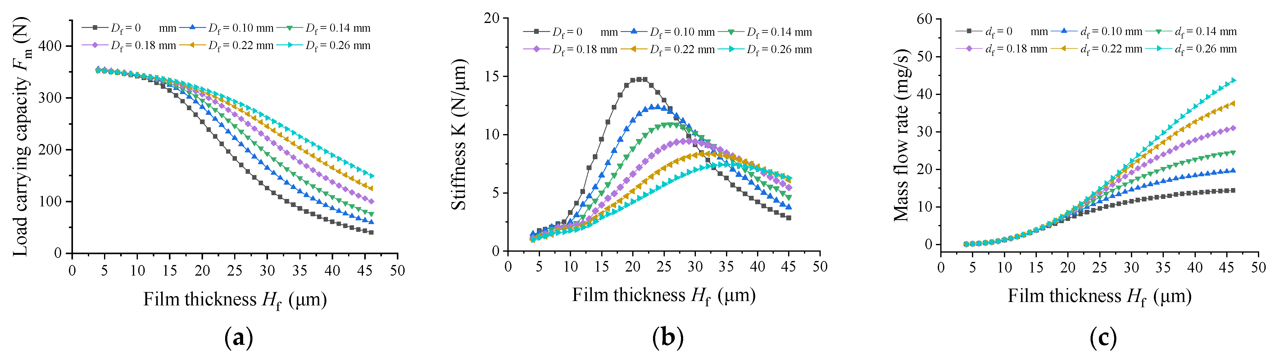
4.3. Effects of the Varying Diameter of Secondary Orifices on Nano−Vibration Characteristics

Simulations were conducted with constant structural parameters and operational conditions to determine the influence of varying secondary orifice diameters on the static and dynamic characteristics. The structural parameters (Hf = 25 μm), the boundary conditions (Ps = 0.5 Mpa and P0 = 0.1 Mpa) and initial conditions for the aerostatic bearings are detailed in Table 1 and Table 2.
Figure 9 illustrates the LCC, stiffness, and mass flow rate of aerostatic bearings concerning varying diameters of secondary orifices. With the increasing diameter of secondary orifices, the LCC of the aerostatic bearings increases, particularly in the presence of larger gas films. Concurrently, as the diameters of the secondary orifices increase, the stiffness decreases initially and then increases while the film thickness remains constant. Additionally, an increase in secondary orifice diameters is correlated with an increase in the mass flow rate. Consequently, the increase in secondary orifice diameters leads to an elevation in the LCC, while the stiffness decreases gradually.
Figure 10 illustrates the pressure distribution, vorticity, and velocity contours of the symmetry plane concerning various diameters of secondary orifices. Notably, as depicted in Figure 10a, with an increase in the diameter of secondary orifices, the pressure distribution in the chamber increases substantially and becomes uniform. Moreover, the amplitude of pressure fluctuations gradually decreases. As illustrated in Figure 10b, an increase in the diameter of secondary orifices leads to increases in the vortex vorticity and complexity near the secondary orifice and between the primary orifice and the secondary orifices. Conversely, the changes in vortex vorticity and complexity distanced from the secondary orifice are negligible. Figure 10c indicates that the increase in the secondary orifice diameter reduce the velocity V1 at both the primary and secondary orifices, accompanied by a gradual decrease in various velocities and velocity fluctuations in the chamber. Moreover, with the increase in the diameter of the secondary orifices, the stability of velocities in the chamber is enhanced. Unlike the aerostatic bearing with an SOR, the pressure distribution in the chamber of the bearing with a PSOR gradually increases with the increase in the diameter of the secondary orifice. Furthermore, compared with the bearing with SOR, the velocity, vortex vorticity intensity, and vortex intricacy for aerostatic bearings with smaller secondary orifice diameters increase because of the complex coupling effects between the primary orifice and secondary orifice. Conversely, these parameters are subdued relative to aerostatic bearings with larger secondary orifice diameters because of the influence of volume ratio. According to the aforementioned analysis, the increase in the diameter of the secondary orifices involves an increase in the total area and mass flow rate of these orifices. Consequently, the distribution of pressure is enhanced, and the velocities at the primary orifice and the secondary orifices decrease. Additionally, the effects of turbulent velocities and the interaction between the primary orifice and secondary orifices are mitigated. Subsequently, increasing the diameter of the secondary orifices inhibits vortex generation and reduces pressure fluctuations.
Figure 11 depicts the 3D iso−surfaces of vorticity in the chamber, demonstrating the influence of varying secondary orifice diameters. With an increase in the diameter of the secondary orifice, the region characterized by turbulent vortices expands gradually. Simultaneously, the vorticity magnitude of turbulent vortices decreases gradually. Furthermore, an increase in the diameter of the secondary orifices enhances the stability and orderliness of the turbulent vortex structures both at the periphery of the secondary orifice and between the primary orifice and the secondary orifices. In comparison with aerostatic bearing with a SOR, as the secondary orifice diameter increases, the area of the turbulent vortex core region first decreases and then increases, while the turbulent intensity first increases and then decreases. Consequently, the augmentation of the secondary orifice diameter effectively inhibits the vortex generation and mitigates the pressure fluctuations.
Figure 12 illustrates the time−varying fluctuation force (Ff) and its corresponding standard deviation (σf) of the DLCC of aerostatic bearings with varying secondary orifice diameters. An increase in the diameter of the secondary orifices leads to a reduction in both the fluctuation force (Ff) and the standard deviation (σf) of the DLCC. The computed results of the fluctuation force are highly consistent with the results obtained through the analyses of turbulent vortices. Thus, noticeable decrease in the secondary orifice diameter yields a discernible reduction in nano−vibrations and an enhancement in system stability.

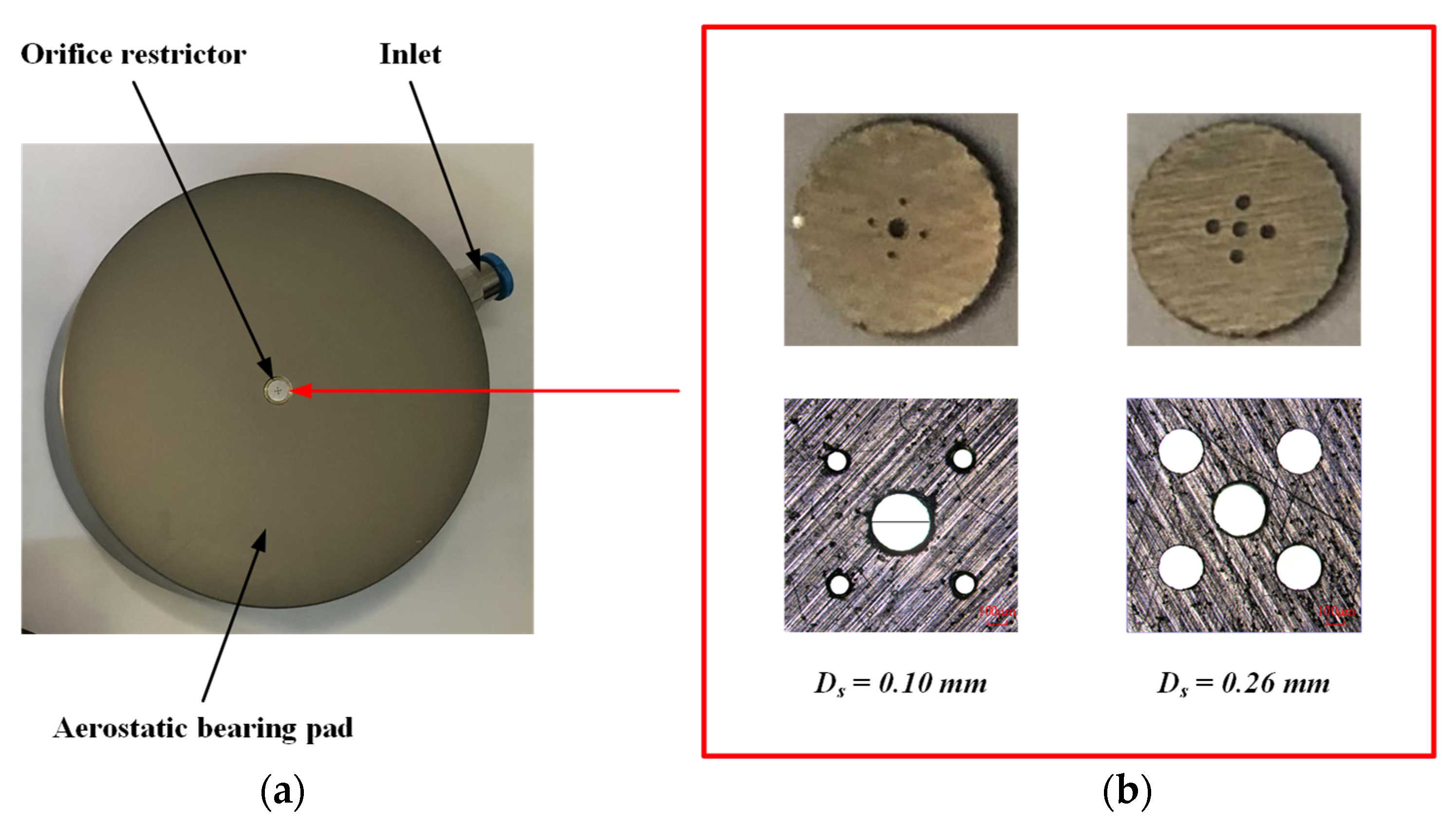
5. Experiment Results

Two experimental configurations were constructed to validate the accuracy of the numerical models and elucidate the underlying suppression mechanism of the PSORs. These setups aimed to measure the LCC and nano−vibration of aerostatic bearings with varying PSORs.

5.1. Tested Aerostatic Bearings

As depicted in Figure 13, the experimental aerostatic bearing comprised two components: the aerostatic bearing pad and the primary and secondary orifice restrictor, both fabricated using cylindrical aluminum alloy. The orifice restrictor, integrated into the chamber of the aerostatic bearing pad, features secondary orifices with varying diameters. Precision techniques such as pico−second laser drilling and ultrasonic technology were employed to manufacture the PSOR, ensuring high quality, uniformity, and small orifice sizes. Figure 13b displays electron microscopy images of the orifice restrictors, showcasing aerostatic bearings with secondary orifice diameters of Ds = 0.1 mm and Ds = 0.26 mm. Furthermore, a SOR is composed of a cylindrical ruby. The structural parameters of three aerostatic bearings with a diameter of 80 mm are listed in Table 4.

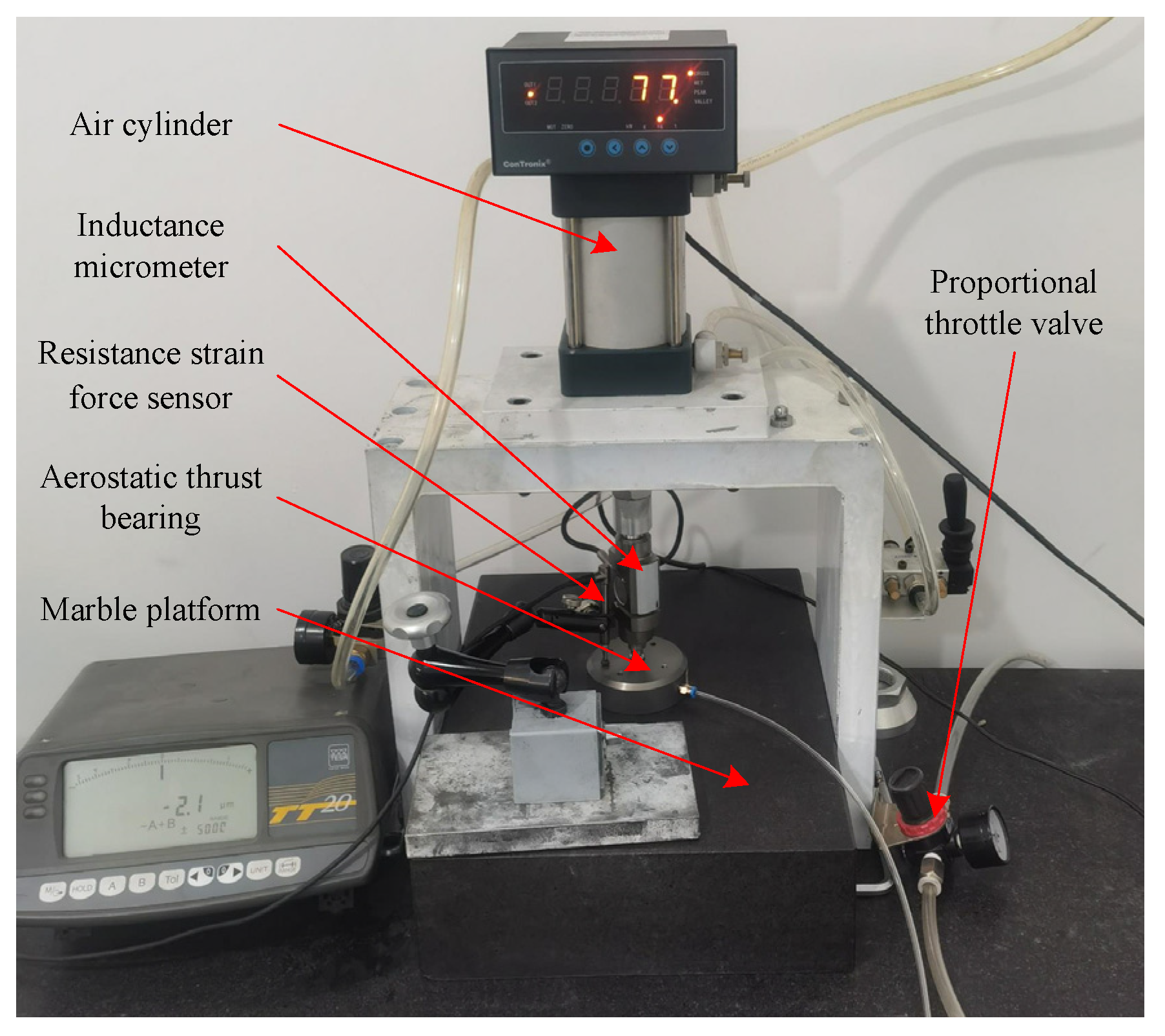
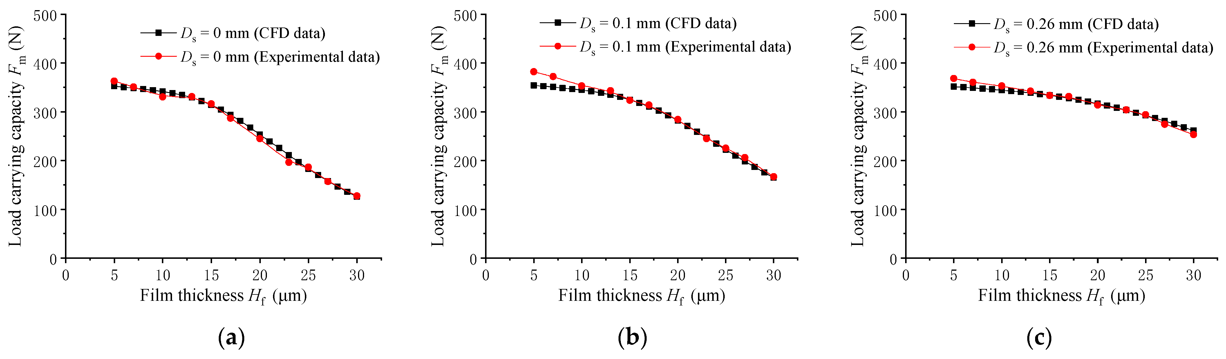
5.2. Load−Carrying Capacity Testing and Analyzing

An experimental platform was constructed for evaluating the static performance, as illustrated in Figure 14. This setup primarily consists of a marble platform, the three tested aerostatic bearings (Type A1, Type A2, and Type B), a proportional throttle valve, a resistance strain force sensor (PBCL, ranging from 200 Kg to 700 Kg; Zhongjing, Shanghai, China), an air cylinder, and an inductance micrometer (TESA® TT20−GTL22 with a 0.1 μm resolution, range ±2 mm; Lausanne Switzerland). The film thickness was recorded by the inductance micrometer affixed to the marble and adjusted by altering the cylinder pressure through the proportional throttle valve. The LCC was measured by the resistance strain force sensor. The mean value was determined through numerous measurements.
The LCC Fm of the three aerostatic bearings is plotted in Figure 15 and can be expressed as a function of film thickness, ranging from 5 to 30 μm, while the supply air pressure is Ps = 0.5 MPa. Notably, the calculation results are highly consistent with the experimental results for all three aerostatic bearings. Notably, their LCC gradually increases with the increase in the diameter of the secondary orifices, especially when the film thickness is relatively large. The results indicated that the enhancement of the secondary orifice diameter effectively increases their LCC, validating the reasonableness of the LES simulation.

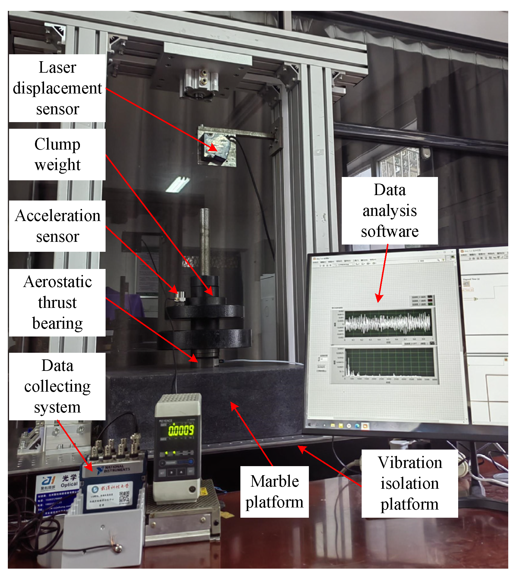
5.3. Nano−Vibration Testing and Analyzing

An experimental platform was constructed for measuring nano−vibrations, as shown in Figure 16. The setup consisted of three aerostatic bearings (Type A1, Type A2, and Type B), different weights, an acceleration sensor (Lancetec−ULT−2015 with 0.000004 g resolution; QUATR, Beijing, China), a laser displacement sensor (LK−G155H with a 0.5 μm resolution; KEYENCE, Osaka, Japan), a marble platform (with roughness < 1 μm), an optical platform, a data acquisition card (NI−9234, 24−bit; Texas, USA), and a personal computer terminal (Lenovo, Beijing, China) with data analysis software (LMS Test Lab, LMS, Texas, USA). The aerostatic bearings were placed on the marble table. The acceleration sensor was installed on the weights. The film thickness was recorded by the laser displacement sensor affixed to the marble and adjusted by varying the weights. The tested nano−vibration data were acquired by the acceleration sensor and processed on the PC terminal using data analysis software. Moreover, all the experiments were conducted on an optical bench with a natural frequency of only 1.5–5 Hz to minimize vibration disturbance from the external environment.
Figure 17 illustrates the experimental acceleration data acquired for three aerostatic bearings in both the time and frequency domains, with a supply pressure of Ps = 0.5 MPa and a film thickness of Hf = 25 μm. Frequency−domain data were acquired through the fast Fourier transform operations on time−domain signals. The dominant frequency peak is primarily concentrated below 1000 Hz. Notably, among these three types of aerostatic bearings, Type A2 exhibited the weakest acceleration amplitude, while Type A2 exhibited the highest acceleration magnitude. Hence, the magnitudes of both the time and frequency domains of the Type B aerostatic bearing exceed those of the Type A2 aerostatic bearing but are lower than the magnitudes of the Type A1 aerostatic bearing. Aerostatic bearings with smaller secondary orifice diameters exacerbate nano−vibrations, whereas those with larger secondary orifice diameters mitigate nano−vibrations, confirming the rationality and effectiveness of the model. The results indicated that the rational optimization design of the PSOR can effectively suppress nano−vibrations in aerostatic bearings, enhancing their stability.

6. Conclusions

This paper introduces a novel aerostatic bearing with a PSOR designed to enhance the LCC, suppress turbulent vortex generation, and alleviate nano−vibrations. The effects of varying secondary orifice diameters on their static and dynamic performance were investigated through numerical simulation and experimentation. The LES method was employed to study the transient flow characteristics of aerostatic bearings with both the SOR and the PSOR to resolve the complex turbulent vortex structure. In addition, the formation mechanism of turbulent vortex and interaction dynamics among the primary orifice and secondary orifices were investigated. The experimental results indicated a high level of consistency with the numerical results, confirming the accuracy of the simulation model and the effectiveness of the PSOR. Increasing the diameter of the secondary orifice can improve the pressure distribution, reduce velocity, and suppress the turbulent vortex formation in the chamber, thereby enhancing the LCC and mitigating pressure fluctuations. Among the five proposed aerostatic bearings, the one with a secondary orifice diameter of 0.1 mm demonstrated the smallest LCC and largest turbulent vortices in the chamber, followed by those with diameters of 0.14 mm, 0.18 mm, and 0.22 mm, respectively. Consequently, the aerostatic bearing with a 0.26 mm secondary orifice, with the largest LCC and the smallest turbulent vortices, demonstrated the most stable structure. Therefore, while increasing the diameter of the secondary orifice enhances the LCC and reduces vibrations, the diameters of excessively large secondary orifices must be selected with caution because of the potential occurrence of the hammer phenomenon.
This study may serve as a valuable point of reference for further understanding and mitigating the nano−vibrations in aerostatic bearings. It provides insights into the formation mechanism of turbulent vortices and the interaction dynamics among the primary orifice and secondary orifices. Future studies may investigate internal airflow field characteristics in aerostatic bearings within the recess using techniques such as particle image velocimetry (PIV).

Author Contributions

Conceptualization, P.Y. and L.Z.; methodology, P.Y. and L.Z.; software, T.Z. and J.L.; validation, P.Y. and T.Z.; writing—review and editing, P.Y. and L.Z.; investigation, M.Z.; resources, P.Y. All authors have read and agreed to the published version of the manuscript.

Funding

This research was funded by the National Natural Science Foundation of China, grant number 51705378; and the Regional Joint Foundation of the National Natural Science Foundation of China, grant number U21A2057.

Data Availability Statement

Data are contained within the article.

Acknowledgments

Numerical calculation is supported by the High−Performance Computing Center of Wuhan University of Science and Technology. The authors would like to thank all the reviewers who participated in the review and MJEditor:www.mjeditor.com (access on 27 November 2023) for their linguistic assistance during the preparation of this manuscript.

Conflicts of Interest

The authors declare no conflict of interest.

Nomenclature

Daerostatic bearing outer diameterViairflows velocity (i = 1, 2, 3, 4, 5, 6, 7)
Dpprimary orifice diameterτwwall shear stress
Dssecondary orifice diameterΔgird element volume
Dcchamber diameterσijviscous stress tensor
Hcheight of compression areaτijsubgrid−scale (SGS) stress
Hrrestrictor heightmmass flow rate
Hfair film thicknessttime
Psair supply pressurexi, xj, xkcoordinates in various directions
P0atmosphere pressureui, uj, ukflow velocities in various directions
Hccylindrical chamber heightReReynolds number
Kstiffness Ttemperature
Lspacing between the primary orifice and the secondary orificeμair viscosity
ρair densityΔxsize of the control volume
pdynamic pressureRideal gas constant
αangle of the flow V3Δttime step size
βangle of the flow V4pddynamic pressure
RijSGS Reynolds stressesFddynamic load−carrying capacity (DLCC)
Cijcross stressesFmmean force
Lijsubgrid−scale Leonard stressesFffluctuation force of the DLCC
δijKronecker delta functionσfstandard deviation of the DLCC

References

  1. Lian, H.; Rong, C.; Li, Y. Influence of Operating Temperature on the Static Characteristics of an Externally Pressurized Thrust Bearing Lubricated with Refrigerant Gas. Tribol. Lett. 2021, 69, 123. [Google Scholar] [CrossRef]
  2. Ise, T.; Arita, N.; Asami, T.; Kawashima, I.; Maeda, T.; Nakajima, T. Experimental study of small−size air turbo blower supported by externally pressurized conical gas bearings. Mech. Mach. Theory 2015, 84, 57–66. [Google Scholar] [CrossRef]
  3. Lu, Z.W.; Zhang, J.A.; Liu, B. Study on the Gas Film Flow Field and its Influencing Factors at the Outlet of the Orifice of the Aerostatic Bearing. Shock Vib. 2020, 2020, 8891382. [Google Scholar] [CrossRef]
  4. Chang, S.H.; Chan, C.W.; Jeng, Y.R. Numerical analysis of discharge coefficients in aerostatic bearings with orifice−type restrictors. Tribol. Int. 2015, 90, 157–163. [Google Scholar] [CrossRef]
  5. Majumdar, B.C. Zero−load stability of a rigid rotor supported on pressurized porous gas bearings. Mech. Mach. Theory 1977, 12, 303–310. [Google Scholar] [CrossRef]
  6. Lohiya, S.H.; Pande, S.S. Analysis of tapered land aerostatic thrust bearing operating under nonsteady loads. Mech. Mach. Theory 1989, 24, 515–521. [Google Scholar] [CrossRef]
  7. Chen, M.F.; Lin, Y.T. Static behavior and dynamic stability analysis of grooved rectangular aerostatic thrust bearings by modified resistance network method. Tribol. Int. 2002, 35, 329–338. [Google Scholar] [CrossRef]
  8. Sahto, M.P.; Wang, W.; Imran, M.; He, L.; Li, H.; Weiwei, G. Modelling and Simulation of Aerostatic Thrust Bearings. IEEE Access 2020, 8, 121299–121310. [Google Scholar] [CrossRef]
  9. Colombo, F.; Lentini, L.; Raparelli, T.; Trivella, A.; Viktorov, V. Dynamic characterisation of rectangular aerostatic pads with multiple inherent orifices. Tribol. Lett. 2018, 66, 133. [Google Scholar] [CrossRef]
  10. Belforte, G.; Raparelli, T.; Trivella, A.; Viktorov, V.; Visconte, C. CFD analysis of a simple orifice−type feeding system for aerostatic bearings. Tribol. Lett. 2015, 58, 25. [Google Scholar] [CrossRef]
  11. Kassab, S.Z. Empirical correlations for the pressure depression in externally pressurized gas bearings. Tribol. Int. 1997, 30, 59–67. [Google Scholar] [CrossRef]
  12. Kassab, S.Z.; Noureldeen, E.M.; Shawky, M.A. Effects of operating conditions and supply hole diameter on the performance of a rectangular aerostatic bearing. Tribol. Int. 1997, 30, 533–545. [Google Scholar] [CrossRef]
  13. Nishio, U.; Somaya, K.; Yoshimoto, S. Numerical calculation and experimental verification of static and dynamic characteristics of aerostatic thrust bearings with small feedholes. Tribol. Int. 2011, 44, 1790–1795. [Google Scholar] [CrossRef]
  14. Boffey, D.A.; Duncan, A.E.; Dearden, J.K. An experimental investigation of the effect of orifice restrictor size on the stiffness of an industrial air lubricated thrust bearing. Tribol. Int. 1981, 14, 287–291. [Google Scholar] [CrossRef]
  15. Boffey, D.; Barrow, A.A.; Dearden, J.K. Experimental investigation into the performance of an aerostatic industrial thrust bearing. Tribol. Int. 1985, 18, 165–168. [Google Scholar] [CrossRef]
  16. Chen, Y.S.; Chiu, C.C.; Cheng, Y.D. Influences of operational conditions and geometric parameters on the stiffness of aerostatic journal bearings. Precis. Eng. 2010, 34, 722–734. [Google Scholar] [CrossRef]
  17. Chen, X.D.; He, X.M. The effect of the recess shape on performance analysis of the gas−lubricated bearing in optical lithography. Tribol. Int. 2006, 39, 1336–1341. [Google Scholar] [CrossRef]
  18. Li, Y.; Han, D. Influences of the geometrical parameters of aerostatic thrust bearing with pocketed orifice −type restrictor on its performance. Tribol. Int. 2007, 40, 1120–1126. [Google Scholar] [CrossRef]
  19. Salem, E.; Kamal, W. Effect of recess geometry on shock wave formation in circular gas bearings. Wear 1978, 46, 351–366. [Google Scholar] [CrossRef]
  20. Talukder, H.M.; Stowell, T.B. Pneumatic hammer in an externally pressurized orifice−compensated air journal bearing. Tribol. Int. 2003, 36, 585–591. [Google Scholar] [CrossRef]
  21. Fourka, M.; Tian, Y.; Bonis, M. Prediction of the stability of air thrust bearings by numerical, analytical and experimental methods. Wear 1996, 198, 1–6. [Google Scholar] [CrossRef]
  22. Kawai, T.; Ebihara, K.; Takeuchi, Y. Improvement of machining accuracy of 5−axis control ultraprecision machining by means of laminarization and mirror surface finishing. CIRP Ann. 2005, 54, 329–332. [Google Scholar] [CrossRef]
  23. Yoshimura, T.; Hanafusa, T.; Kitagawa, T.; Hirayama, T.; Matsuoka, T.; Yabe, H. Clarifications of the mechanism of nano−fluctuation of aerostatic thrust bearing with surface restriction. Tribol. Int. 2012, 48, 29–34. [Google Scholar] [CrossRef]
  24. Chen, X.; Han, C.; Xin, L.; Ye, Y.; Hu, Y.; Xu, J. Air Vortices and Nano−Vibration of Aerostatic Bearings. Tribol. Lett. 2011, 42, 179–183. [Google Scholar] [CrossRef]
  25. Eleshaky, M.E. CFD investigation of pressure depressions in aerostatic circular thrust bearings. Tribol. Int. 2009, 42, 1108–1117. [Google Scholar] [CrossRef]
  26. Otsu, Y.; Somaya, K.; Yoshimoto, S. High−speed stability of a rigid rotor supported by aerostatic journal bearings with compound restrictors. Tribol. Int. 2011, 44, 9–17. [Google Scholar] [CrossRef]
  27. Wang, P.; Zhang, Y.; Feng, L.; Hou, W.; Wang, J.; Li, W.; Feng, K. Study on the pneumatic hammer phenomenon of aerostatic bearings based on the empirical mode method: Numerical and experimental analysis. Tribol. Int. 2023, 181, 108305. [Google Scholar] [CrossRef]
  28. Aoyama, T.; Kakinuma, Y.; Kobayashi, Y. Numerical and Experimental Analysis for the Small Vibration of Aerostatic Guideways. CIRP Ann.—Manuf. Technol. 2006, 55, 419–422. [Google Scholar] [CrossRef]
  29. Ma, W.; Cui, J.; Liu, Y.; Tan, J. Improving the pneumatic hammer stability of aerostatic thrust bearing with recess using damping orifices. Tribol. Int. 2016, 103, 281–288. [Google Scholar] [CrossRef]
  30. Zhu, J.; Chen, H.; Chen, X. Large eddy simulation of vortex shedding and pressure fluctuation in aerostatic bearings. J. Fluids Struct. 2013, 40, 42–51. [Google Scholar] [CrossRef]
  31. Yifei, L.; Yihui, Y.; Hong, Y.; Xinen, L.; Jun, M.; Hailong, C. Modeling for optimization of circular flat pad aerostatic bearing with a single central orifice−type restrictor based on CFD simulation. Tribol. Int. 2017, 109, 206–216. [Google Scholar] [CrossRef]
  32. Chen, X.; Chen, H.; Zhu, J.; Jiang, W. Vortex suppression and nano−vibration reduction of aerostatic bearings by arrayed microhole restrictors. J. Vib. Control 2017, 23, 842–852. [Google Scholar] [CrossRef]
  33. Feng, K.; Wang, P.; Zhang, Y.; Hou, W.; Cui, H. Novel 3−D printed aerostatic bearings for the improvement of stability: Theoretical predictions and experimental measurements. Tribol. Int. 2021, 163, 107149. [Google Scholar] [CrossRef]
  34. Yu, P.; Lu, J.; Luo, Q.; Li, G.; Yin, X. Optimization Design of Aerostatic Bearings with Square Micro−Hole Arrayed Restrictor for the Improvement of Stability: Theoretical Predictions and Experimental Measurements. Lubricants 2022, 10, 295. [Google Scholar] [CrossRef]
  35. Li, L.; Lou, J.; Nishikawa, H.; Luo, H. Reconstructed Discontinuous Galerkin Methods for Compressible Flows Based on a New Hyperbolic Navier−Stokes system. J. Comput. Phys. 2020, 427, 110058. [Google Scholar] [CrossRef]
  36. Li, Y.; Zhao, J.; Zhu, H.; Lin, Y. Numerical analysis and experimental study on the microvibration of an aerostatic thrust bearing with a pocketed orifice−type restrictor. ARCHIVE Proc. Inst. Mech. Eng. Part J J. Eng. Tribol. 1994−1996 (Vols 208–210) 2014, 229, 609–623. [Google Scholar] [CrossRef]
  37. Nicoud, F.; Ducros, F. Subgrid−Scale Stress Modelling Based on the Square of the Velocity Gradient Tensor. Flow Turbul. Combust. 1999, 62, 183–200. [Google Scholar] [CrossRef]
  38. Issa, R.I. Solution of the implicitly discretised fluid flow equations by operator−splitting. J. Comput. Phys. 1991, 62, 40–65. [Google Scholar] [CrossRef]
Figure 1. Structure diagram and the operational principle of aerostatic bearing with a single chamber: (a) bottom view; (b) cross−section view.
Lubricants 11 00518 g001
Figure 2. Cloud diagram of airflow field along the symmetrical plane: (a) pressure; (b) vorticity.
Lubricants 11 00518 g002
Figure 3. Schematic diagram of the aerostatic bearings with a PSOR: (a) bottom view of aerostatic bearing; (b) cross−section view of aerostatic bearing; (c) bottom view of PSOR.
Lubricants 11 00518 g003
Figure 4. Type A aerostatic bearing: (a) computational domain and boundary conditions; (b) computational grids.
Lubricants 11 00518 g004
Figure 5. Mechanism of formation and evolution of turbulent vortices in a multi−orifice restrictor.
Lubricants 11 00518 g005
Figure 6. The 2D transient flow structures in the chamber of aerostatic thrust bearing with PSOR.
Lubricants 11 00518 g006
Figure 7. Iso−surfaces of instantaneous pressure about the vortex core region in chamber.
Lubricants 11 00518 g007
Figure 8. Time−varying fluctuation force of the DLCC of aerostatic thrust bearing with PSOR.
Lubricants 11 00518 g008
Figure 9. (a) LCC; (b) stiffness; (c) mass flow rate.
Lubricants 11 00518 g009
Figure 10. (a) Pressure distribution; (b) vorticity; (c) velocity contours.
Lubricants 11 00518 g010
Figure 11. Iso−surfaces of vorticity in the chamber.
Lubricants 11 00518 g011
Figure 12. The DLCC of aerostatic bearings with varying diameters of secondary orifices: (a) time−varying fluctuation force; (b) standard deviation of DLCC.
Lubricants 11 00518 g012
Figure 13. (a) Photograph of type A aerostatic thrust bearing; (b) shape inspection of PSOR by electron microscope.
Lubricants 11 00518 g013
Figure 14. Static performance experimental platform.
Lubricants 11 00518 g014
Figure 15. Comparing the experimental and numerical results: (a)Type B; (b) Type A1; (c) Type A2,.
Lubricants 11 00518 g015
Figure 16. Photo of experiment platform for vibration.
Lubricants 11 00518 g016
Figure 17. (a) Acceleration signal in the time domain for three aerostatic bearings; (b) acceleration signal in the frequency domain for three aerostatic bearings.
Lubricants 11 00518 g017
Table 1. Structural parameters of aerostatic bearings with PSORs.
TypeRestrictorPrimary Orifice
Diameter
Dp (mm)
Secondary Orifice
Diameter
Ds (mm)
Spacing
L (mm)
Chamber
Height
Hc (mm)
Chamber
Diameter
Dc (mm)
Bearing
Diameter
D (mm)
Orifice
Height
Hr (mm)
A1 Po + 4 So0.30.10~0.260.50.15800.3
B1 Po0.3000.15800.3
Table 2. Physical constants of the ideal air.
Air TemperatureDensitySpecific HeatHeat ConductivityViscosityMolecular Weight
293.15 K1.202 kg/m31006.43 J/(kg·K)0.0242 W/(m·K)1.7894 × 10−5 kg/(m·s)28.966 × 10−3 kg/mol
Table 3. Grid independence analysis, where Δ denotes gird element volume (μm3).
TypeChamberOrificeAir Filmy+maxTotal
Number
Mean Force
Fm/N
Standard Deviation
σf
ΔminΔmaxΔminΔmaxΔminΔmax
11.51171421.6681.2789462601.841,418,400320.220.530
21.10120321.6681.27137596301.512,181,621324.720.525
30.5546921.6681.27137596300.653,278,216325.160.527
40.0328121.6681.27110356430.464,134,320325.060.522
Table 4. Structural parameters of aerostatic bearings.
TypeRestrictorPrimary Orifice Diameter
Dp (mm)
Secondary Orifice Diameter
Ds (mm)
Spacing
L (mm)
Chamber Height
Hc (mm)
Chamber
Diameter
Dc (mm)
Orifice Height
Hr (mm)
A11 Po + 4 So0.30.100.50.150.3
A21 Po + 4 So0.30.260.50.150.3
B1 Po0.3000.150.3
Disclaimer/Publisher’s Note: The statements, opinions and data contained in all publications are solely those of the individual author(s) and contributor(s) and not of MDPI and/or the editor(s). MDPI and/or the editor(s) disclaim responsibility for any injury to people or property resulting from any ideas, methods, instructions or products referred to in the content.

