Experimental Study of Piezoelectric Control for Changing Tilting Pad Journal Bearing Circumferential Angle and Radial Displacement


Abstract
:1. Introduction
2. Experimental Procedure
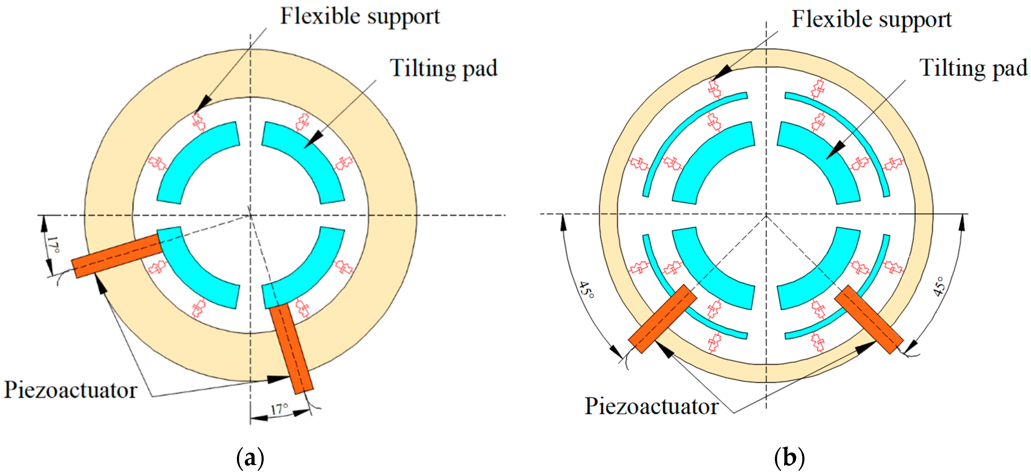
2.1. Test Bearings
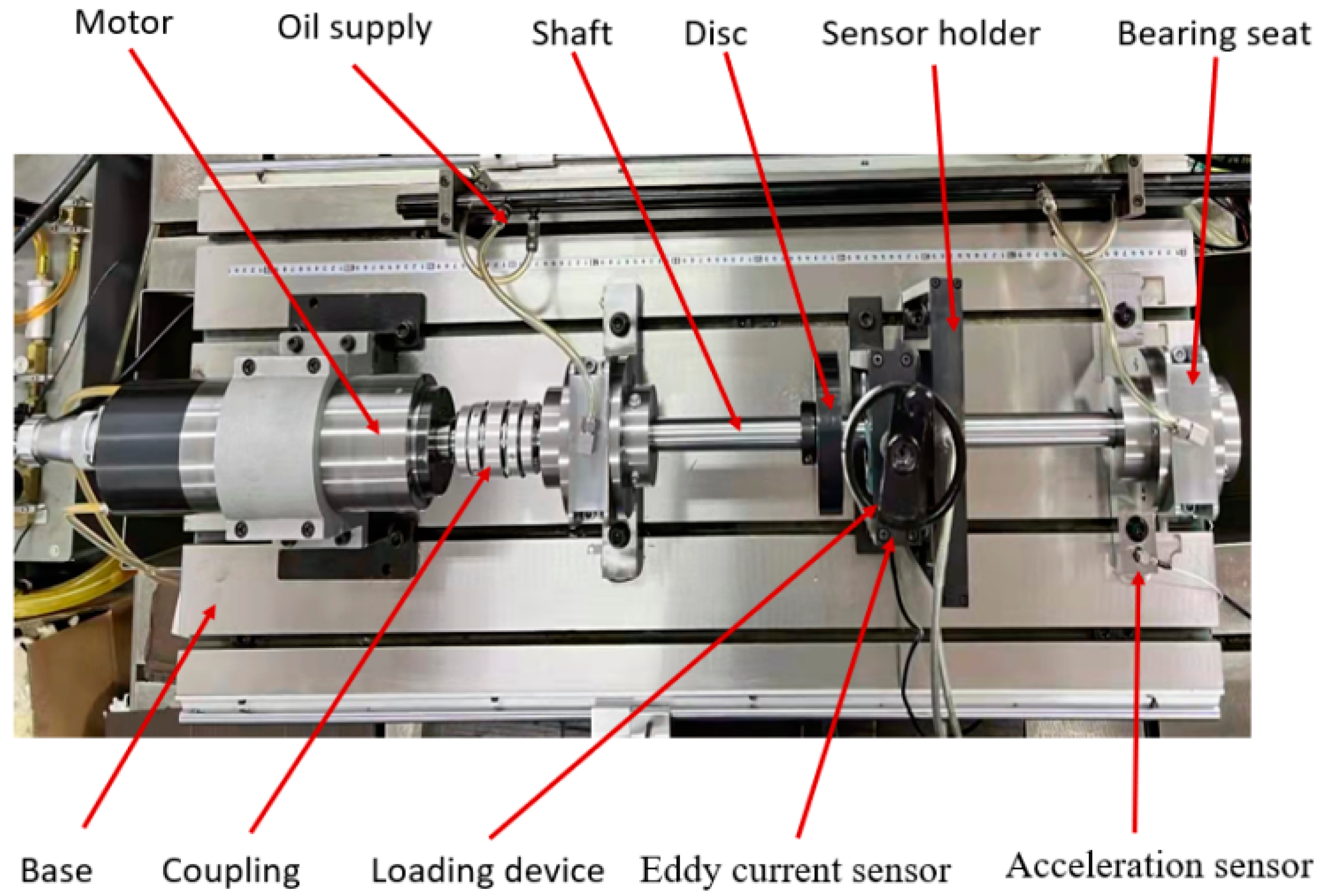
2.2. Experimental Setup
3. Control of Tilting Pad Bearing–Rotor System
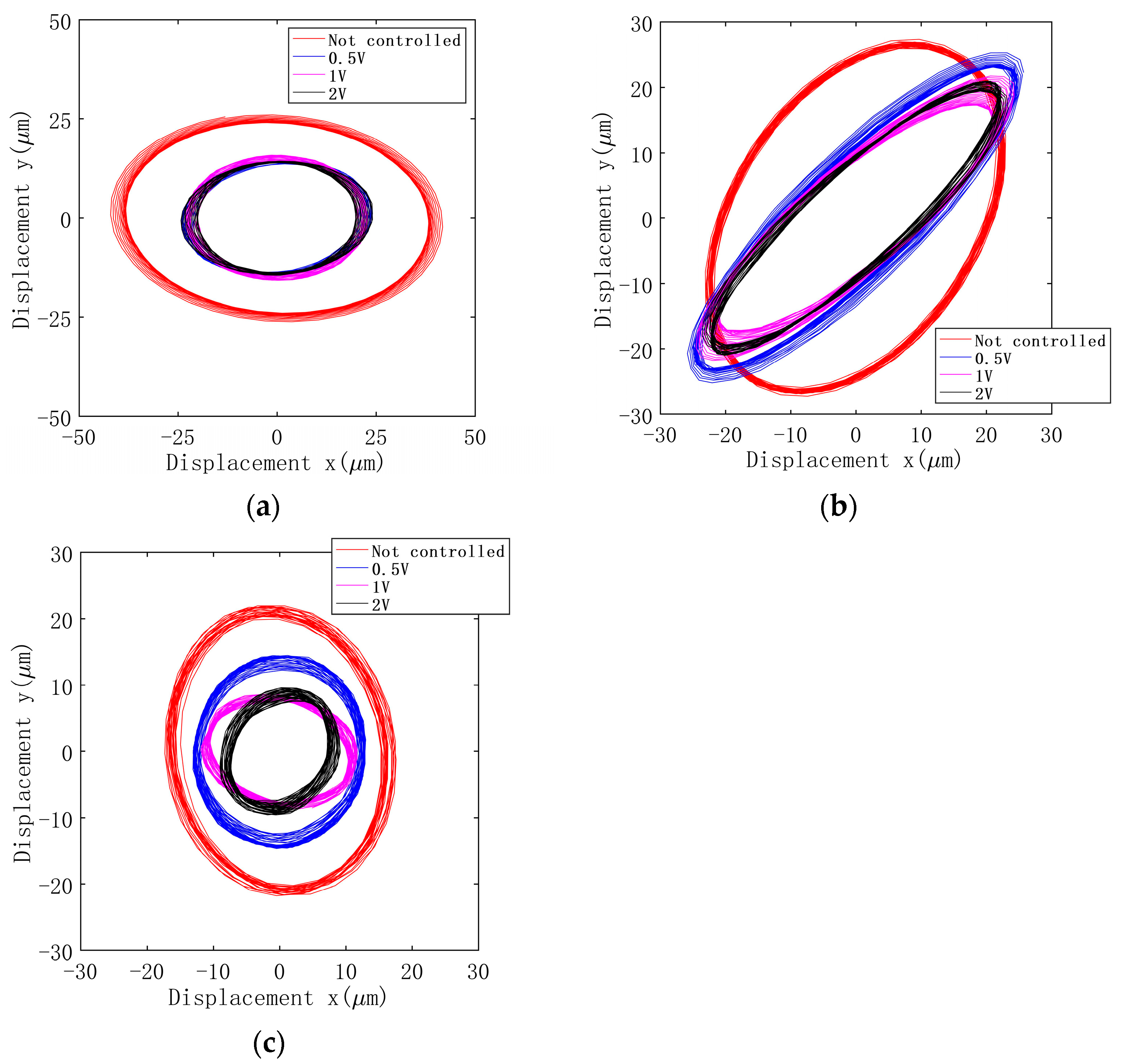
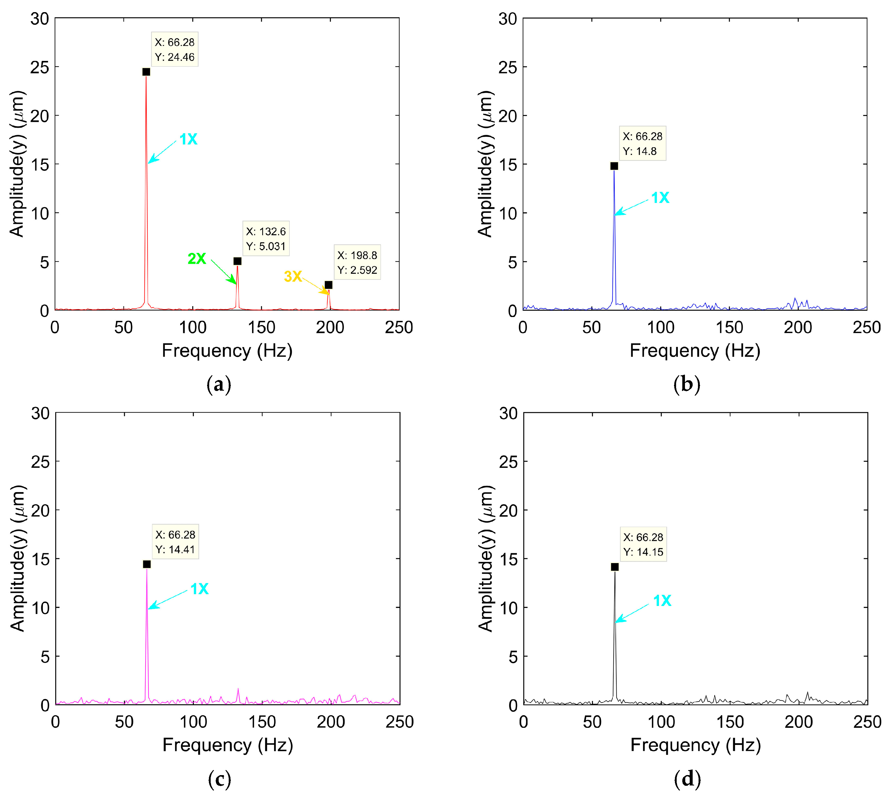
3.1. Experimental Results of Angle Bearing Control
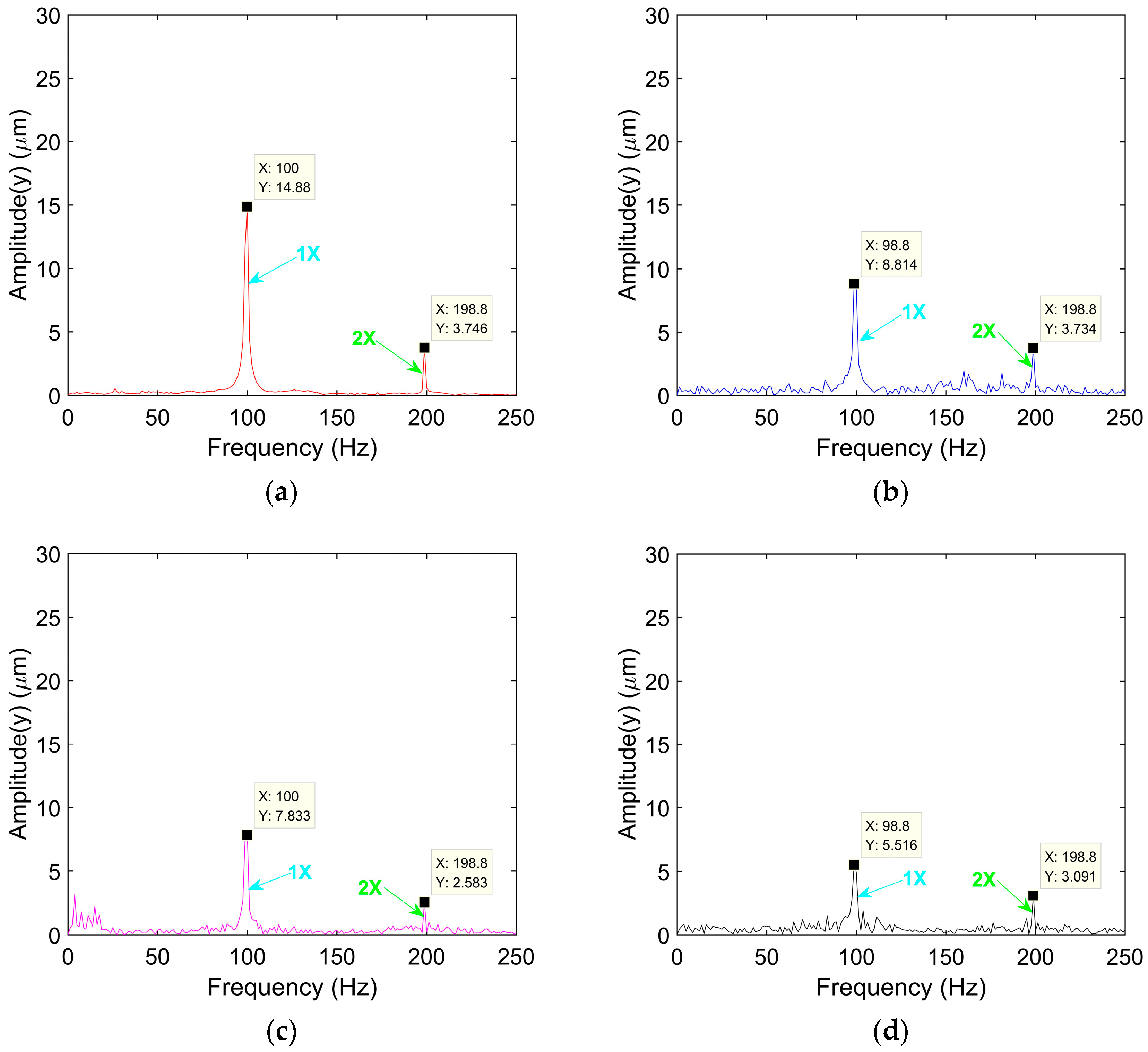
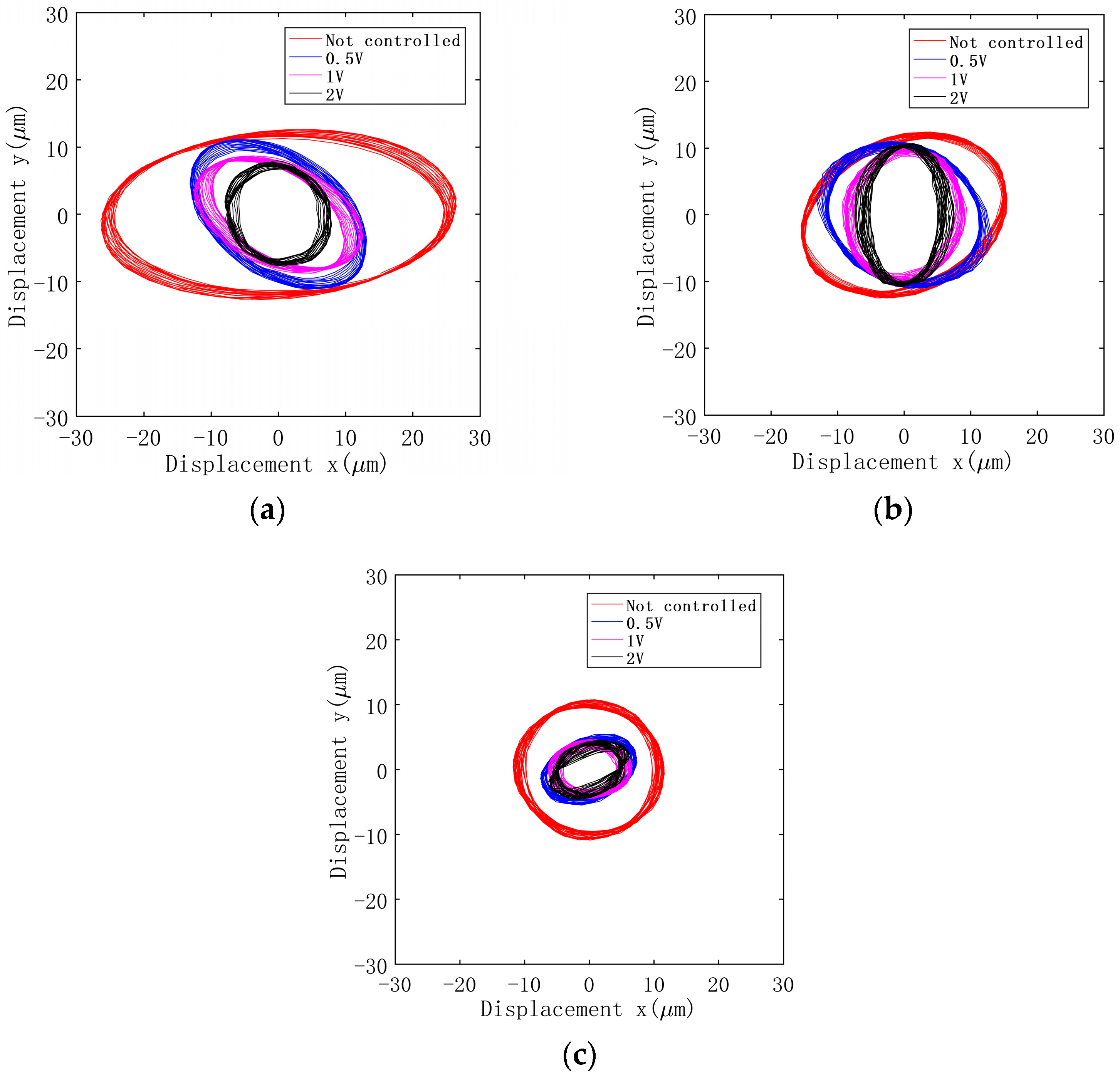
3.2. Experimental Results of Displacement Bearing Control
4. Discussions
5. Conclusions
- (1)
- The flexible bearing–rotor test bench was established, and two kinds of structural bearings were designed and manufactured. The circumferential angle of the disk of the angle bearing and the radial displacement of the disk of the displacement bearing are successfully controlled by the piezoelectric actuator, and the axial trajectory and spectrum of the bearing at different rotational speeds are obtained.
- (2)
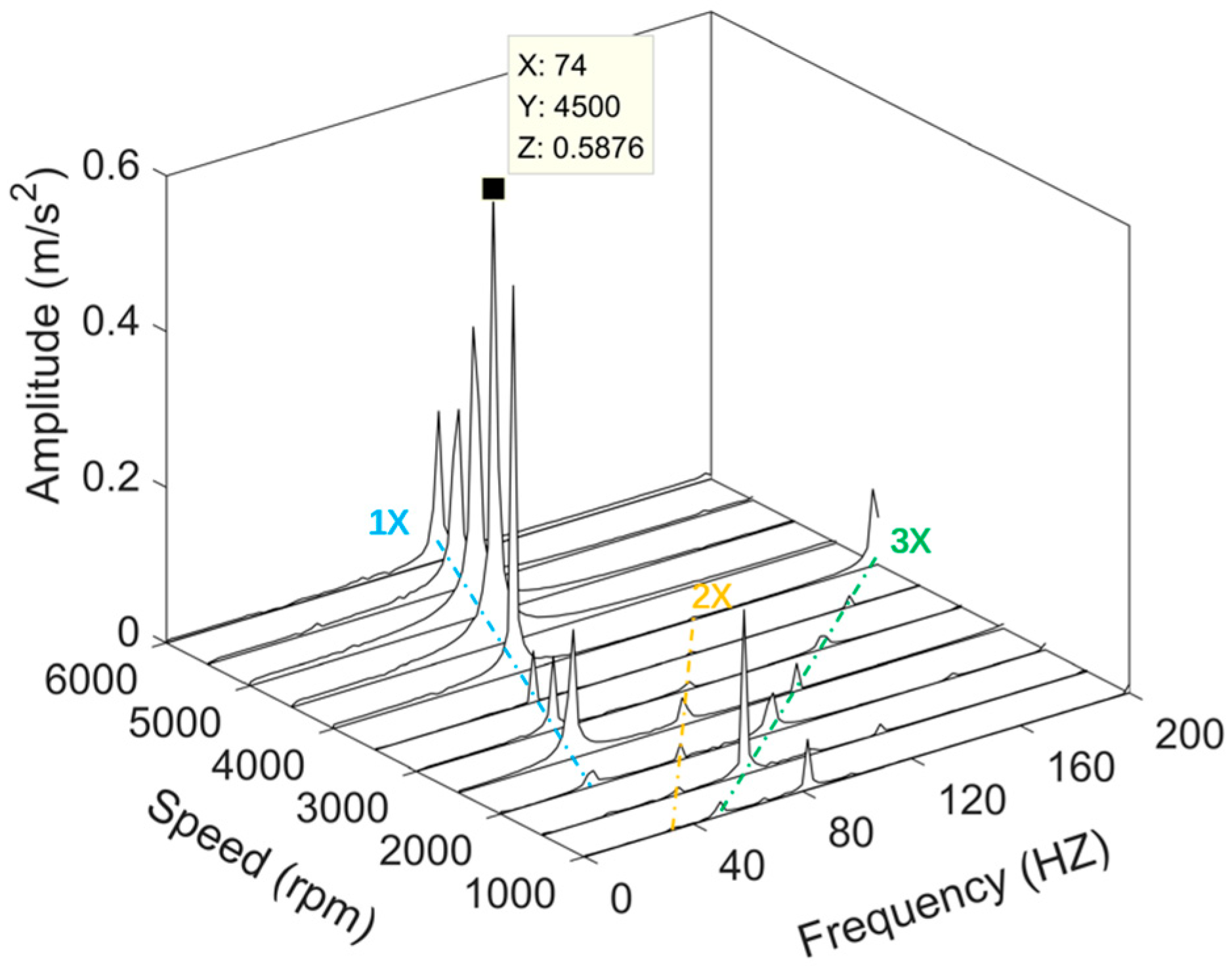
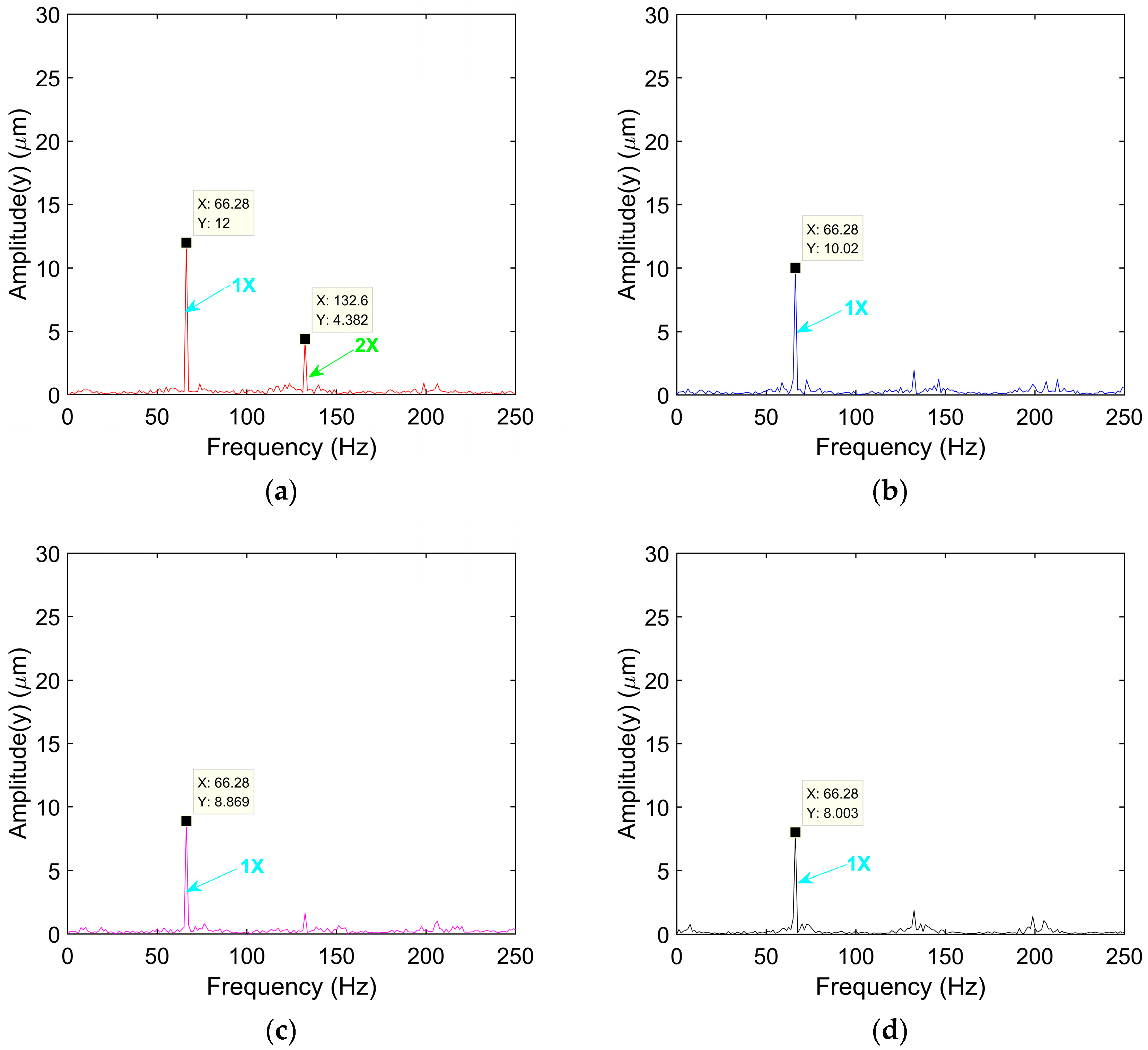
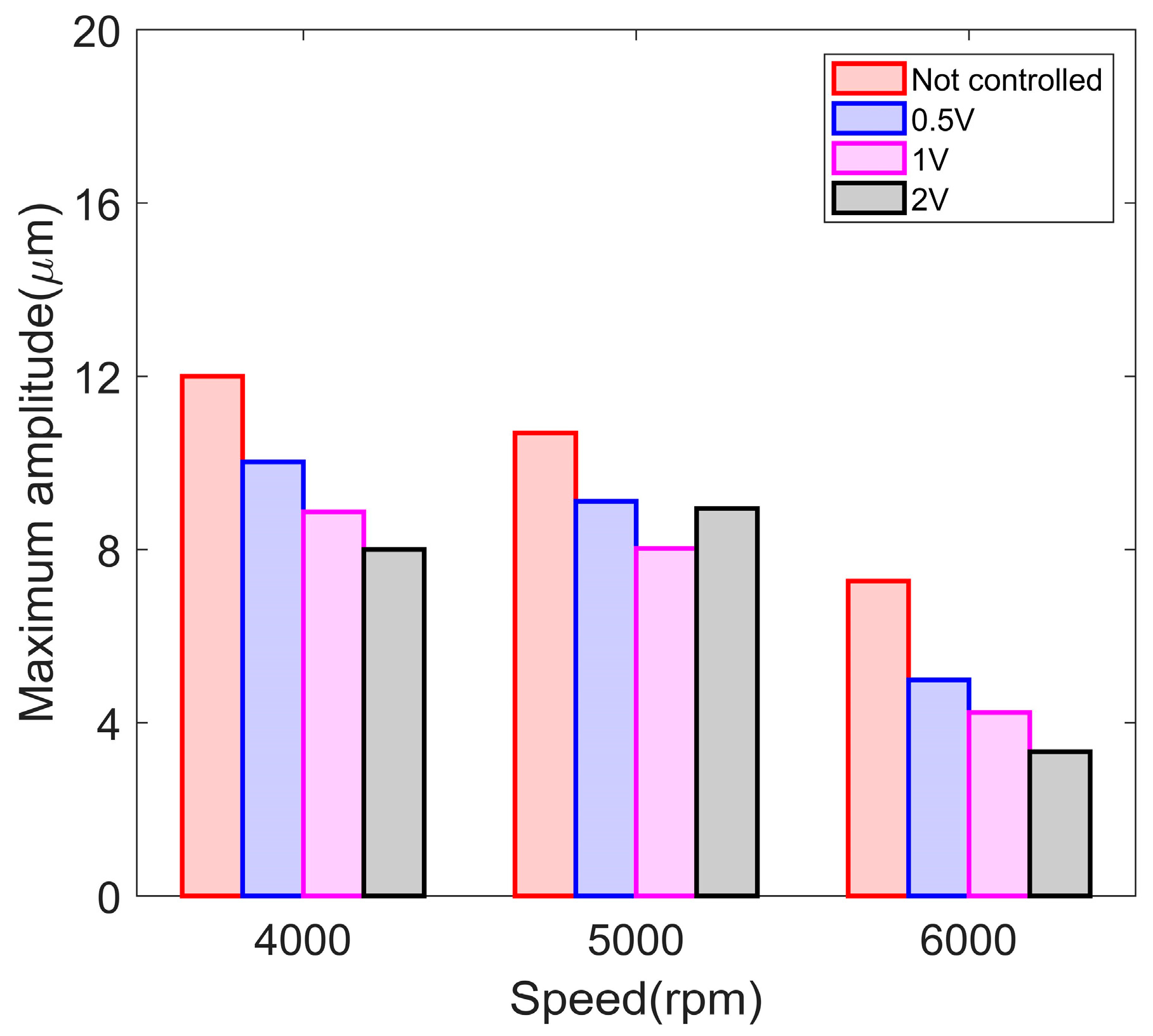
- The research results of angle control show that the axis trajectory of the piezo-controlled angular bearing–rotor system decreases significantly at 4000 rpm, and the peak displacement of fundamental frequency decreases by 62% at 6000 rpm. This indicates that by controlling the swing angle of the bearing bush, a steeper wedge gap is formed between the bearing bush and the rotor shaft, thereby increasing the oil film pressure and bearing capacity, and suppressing the spindle vibration.
- (3)
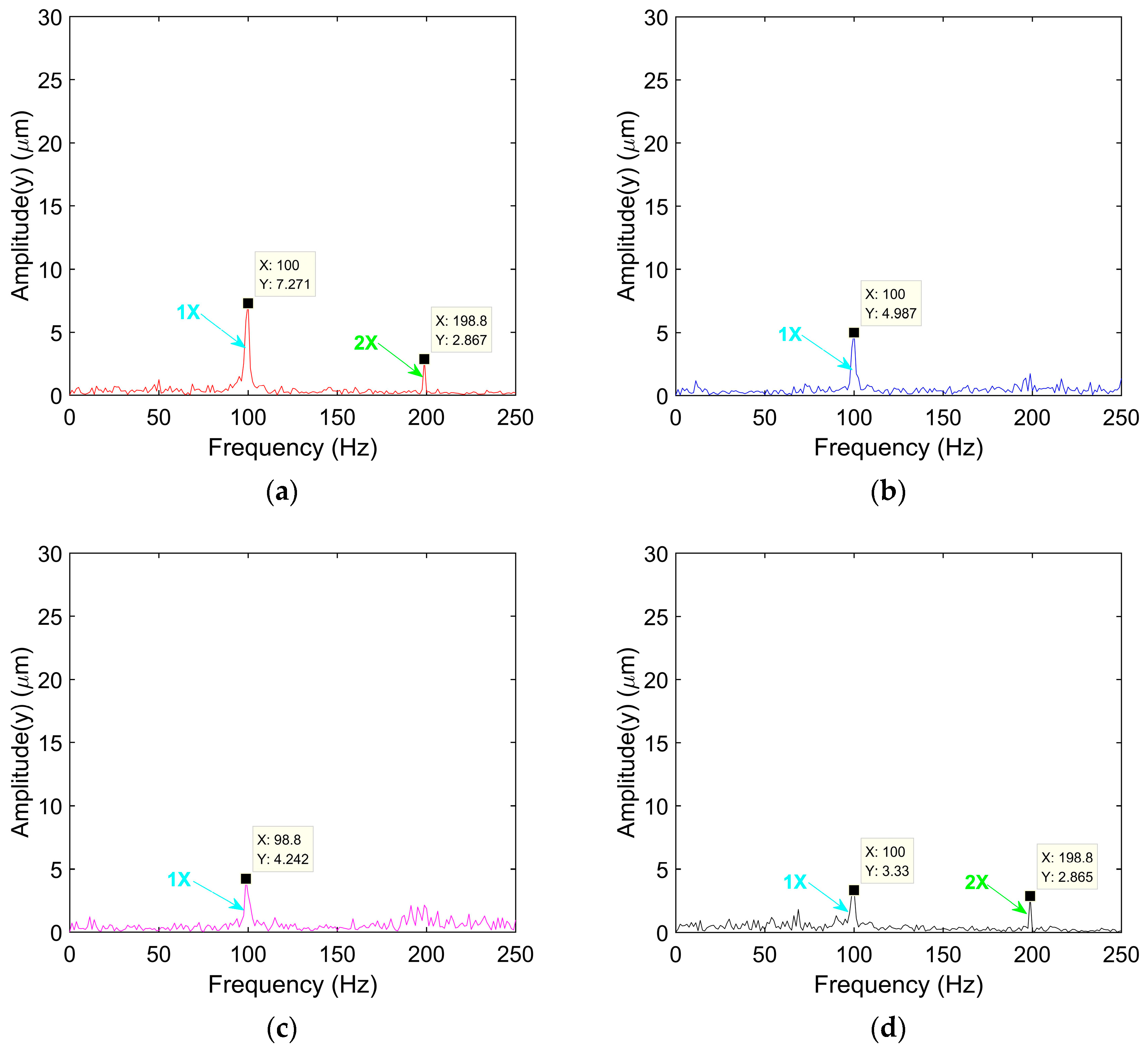
- The displacement control results show that with the increase of the radial displacement control amount of the bearing bush, the axial trajectory of the rotor journal becomes smaller and closer to the bearing center. At 6000 rpm, the axis track area decreases obviously, and the peak displacement of the fundamental frequency decreases by 54%. The radial displacement of the bushing reduces the radius clearance of the bearing, changes the damping coefficient and stiffness coefficient of the bearing, and thus adjusts the vibration amplitude of the rotor.
- (4)
- According to conclusions 2 and 3, the vibration performance of two new tilting pad bearing–rotor systems is improved by the piezoelectric control of the bearing’s circumaxial angle and radial displacement, and the internal geometric parameters of the bearing are changed, thus laying a technical foundation for the realization of intelligent bearings.
Author Contributions
Funding
Data Availability Statement
Conflicts of Interest
References
- Delgado, A.; Vannini, G.; Ertas, B.; Drexel, M.; Naldi, L. Identification and Prediction of Force Coefficients in a Five-Pad and Four-Pad Tilting Pad Bearing for Load-on-Pad and Load-Between-Pad Configurations. ASME J. Eng. Gas Turbines Power 2011, 133, 092503. [Google Scholar] [CrossRef]
- Suh, J.; Palazzolo, A. Three-dimensional dynamic model of TEHD tilting-pad journal bearing—Part I: Theoretical modeling. J. Tribol. 2015, 137, 041703. [Google Scholar] [CrossRef]
- Zhang, Z. Fluid Dynamic Lubrication Theory of Sliding Bearings; Higher Education Press: Beijing, China, 1986. (In Chinese) [Google Scholar]
- Hei, D.; Lü, Y.; Zhang, Y. Nonlinear Dynamic Characteristics of Rotor Supported by Fixed-Tilting-Pad Bearings. J. Mech. Strength 2016, 38, 940–946. (In Chinese) [Google Scholar]
- Amamou, A.; Chouchane, M. Nonlinear stability analysis of long hydrodynamic journal bearings using numerical continuation. Mech. Mach. Theory 2014, 72, 17–24. [Google Scholar] [CrossRef]
- Feng, K.; Liu, W.; Zhang, Z.; Zhang, T. Theoretical model of flexure pivot tilting pad gas bearings with metal mesh dampers in parallel. Tribol. Int. 2016, 94, 26–38. [Google Scholar] [CrossRef]
- Chen, S.; Xiong, W.; Lu, C.; Ma, J. Research on Static and Dynamic Characteristics of Flexure-pivot Tilting Pad Journal Bearings. J. Vib. Shock 2018, 37, 236–241. (In Chinese) [Google Scholar]
- Santos, I. Controllable Sliding Bearings and Controllable Lubrication Principles—An Overview. Lubricants 2018, 6, 16. [Google Scholar] [CrossRef]
- Breńkacz, Ł.; Witanowski, Ł.; Drosińska-Komor, M.; Szewczuk-Krypa, N. Research and applications of active bearings: A state-of-the-art review. Mech. Syst. Signal Process. 2021, 151, 107423. [Google Scholar] [CrossRef]
- Das, A.S.; Dutt, J.K.; Ray, K. Active vibration control of unbalanced flexible rotor-shaft systems parametrically excited due to base motion. Appl. Math. Model. 2010, 34, 2353–2369. [Google Scholar] [CrossRef]
- Silva HA, P.; Nicoletti, R. Rotor vibration control using tilting-pad journal bearing with active pads—Numerical and experimental results. J. Sound Vib. 2023, 546, 117441. [Google Scholar] [CrossRef]
- Santos, I.F. Design and evaluation of two types of active tilting pad journal bearings. In Active Control of Vibration; Burrows, C.R., Keogh, P.S., Eds.; Mechanical Engineering Publications Ltd.: London, UK, 1994; pp. 79–87. [Google Scholar]
- Bently, D.E.; Grant, J.W.; Hanifan, P.C. Active Controlled Hydrostatic Bearings for a New Generation of Machines. ASME 2000, 2000, V002T03A011. [Google Scholar]
- Bently, D.E.; Eldridge, T.; Jensen, J.; Mol, P. Externally Pressurized Bearings Allow Rotor Dynamic Optimization. VDI Ber. 2001, 1640, 49–62. [Google Scholar]
- Morosi, S.; Santos, I.F. Active Lubrication Applied to Radial Gas Journal Bearings. Part 1: Modelling. Tribol. Int. 2011, 44, 1949–1958. [Google Scholar] [CrossRef]
- Morosi, S.; Santos, I.F. Experimental Investigations of Active Air Bearings. ASME 2012, 44731, 901–910. [Google Scholar]
- Pierart, F.; Santos, I.F. Steady State Characteristics of an Adjustable Hybrid Gas Bearing—CFD, Modified Reynolds Equation and Experimental Validation. J. Eng. Tribol. Proc. IMechE Part J. 2015, 229, 807–822. [Google Scholar] [CrossRef]
- Santos, I.F. On the Adjusting of the Dynamic Coefficients of Tilting-Pad Journal Bearings. Tribol. Trans. 1995, 38, 700–706. [Google Scholar] [CrossRef]
- Santos, I.F.; Nicoletti, R. Influence of orifice distribution on the thermal and static properties of hybridly lubricated bearings. Int. J. Mech. Sci. 2001, 38, 2069–2081. [Google Scholar] [CrossRef]
- Santos, I.F.; Scalabrin, A. Control System Design for Active Lubrication with Theoretical and Experimental Examples. J. Eng. Gas Turbines Power 2003, 125, 75–80. [Google Scholar] [CrossRef]
- Liu, H.; Gong, X.; Wang, J. Vibration Active Control of Rotor System Based on Active Lubricated Tilting-Pad Bearings. Strength Environ. 2011, 38, 8–17. (In Chinese) [Google Scholar]
- Gong, X.C.; Qin, Y.L. Vibration Control of Unsymmetrical Rotating Machinery with an Active Tilting Pad Journal Bearing. In Proceedings of the 2021 IEEE International Conference on Sensing, Diagnostics, Prognostics, and Control (SDPC), Weihai, China, 13–15 August 2021; pp. 260–269. [Google Scholar]
- Chasalevris, A.; Dohnal, F. A journal bearing with variable geometry for the suppression of vibrations in rotating shafts: Simulation, design, construction and experiment. Mech. Syst. Signal Process. 2015, 52–53, 506–528. [Google Scholar] [CrossRef]
- Deckler, D.C.; Veillette, R.J.; Braun, M.J.; Choy, F.K. Simulation and Control of an Active Tilting-pad Journal Bearing. Tribol. Trans. 2004, 47, 440–458. [Google Scholar] [CrossRef]
- Da Silveira, A.R.G.; Daniel, G.B. Piezoelectric harvester for smart tilting pad journal bearings. Energy Convers. Manag. 2020, 205, 112338. [Google Scholar] [CrossRef]
- Da Silveira, A.R.G.; Daniel, G.B. Optimization analysis of an energy harvester for smart tilting pad journal bearings considering higher vibration modes. Mech. Syst. Signal Process. 2022, 166, 108404. [Google Scholar] [CrossRef]
- Yan, L.; Yanhua, S.; Lie, Y. Active control of unbalance response of rotor systems supported by tilting-pad gas bearings. Eng. Tribol. 2012, 226, 87–99. [Google Scholar]
- Mizumoto, H.; Arii, S.; Yabuta, Y.; Tazoe, Y. Vibration control of a high-speed air-bearing spindle using an active aerodynamic bearing. In ICCAS 2010; IEEE: New York, NY, USA, 2010; pp. 2261–2264. [Google Scholar]
- Chang, J.; Ma, J.; Lu, C.; Chen, S. Active Control of Unbalance Response of Rotor Systems Supported by Flexible Hinge Tilting-Pad Bearings. Comb. Mach. Tools Autom. Manuf. Technol. 2017, 2017, 97–100. (In Chinese) [Google Scholar]
- Wang, Q. Dynamic Characteristics and Active Control Study of Dynamic and Static Pressure Flexible Hinge Tilting-Pad Bearings. Ph.D. Thesis, Shandong University, Jinan, China, 2017. [Google Scholar]
- Chen, R.; Ouyang, W.; Shi, Z.; Wei, Y.; Yuan, X. Characteristic Analysis and Simulated Test of Hybrid Bearing with the Introduction of Piezoelectric Controller. J. Shock Vib. 2016, 2016, 6874741. (In Chinese) [Google Scholar] [CrossRef]
- Qin, X.; Ji, D.; Wang, X.; Qiu, Z.; Zhu, Y. Simulation Study on Dynamic Performance of Active Control Tilting-Pad Bearing-Rotor System. Ind. Control Comput. 2022, 35, 100–101. (In Chinese) [Google Scholar]
- Girish, H.; Pai, R. Dynamic performance and stability characteristics of a multi-pad externally adjustable fluid film bearing. Aust. J. Mech. Eng. 2022, 1–16. [Google Scholar] [CrossRef]
- Huang, G.; Wang, X.; Qin, X.; Zhu, L.; Yi, S. Experimental investigation of dynamic behavior of rotor system with a novel double layers flexible support tilting pad bearing. Adv. Mech. Eng. 2022, 14, 16878132221116482. [Google Scholar] [CrossRef]
- Schweizer, B. Oil whirl, oil whip and whirl/whip synchronization occurring in rotor systems with full-floating ring bearings. Nonlinear Dyn. 2009, 57, 509–532. [Google Scholar] [CrossRef]
- De Castro, H.F.; Cavalca, K.L.; Nordmann, R. Whirl and whip instabilities in rotor-bearing system considering a nonlinear force model. J. Sound Vib. 2008, 317, 273–293. [Google Scholar] [CrossRef]


| Parameters | Angle Bearing/Displacement Bearing |
|---|---|
| Bearing pad radius (R), mm | 15.05 |
| Bearing length (B), mm | 25 |
| Manufactured diameter clearance (c), mm | 0.1 |
| Preload factor (m) | 0.375 |
| Pad arc angle (°) | 70 |
| Number of pads | 4 |
| Thickness of pads (t), mm | 5 |
| Parameters | Value |
|---|---|
| Young’s modulus (E), GPa | 210 |
| Density (), kg/m3 | 7850 |
| Poisson’s ratio ) | 0.3 |
| Shaft diameter (d), mm | 30 |
| Shaft length (L), mm | 750 |
| Mass of disk (m), kg | 5.76 |
| Mass of shaft (M), kg | 4.17 |
| Supply oil pressure (P), MPa | 0.1 |
| Type of lubricant | ISO-VG32 |
| Oil inlet temperature (°C) | 35 |
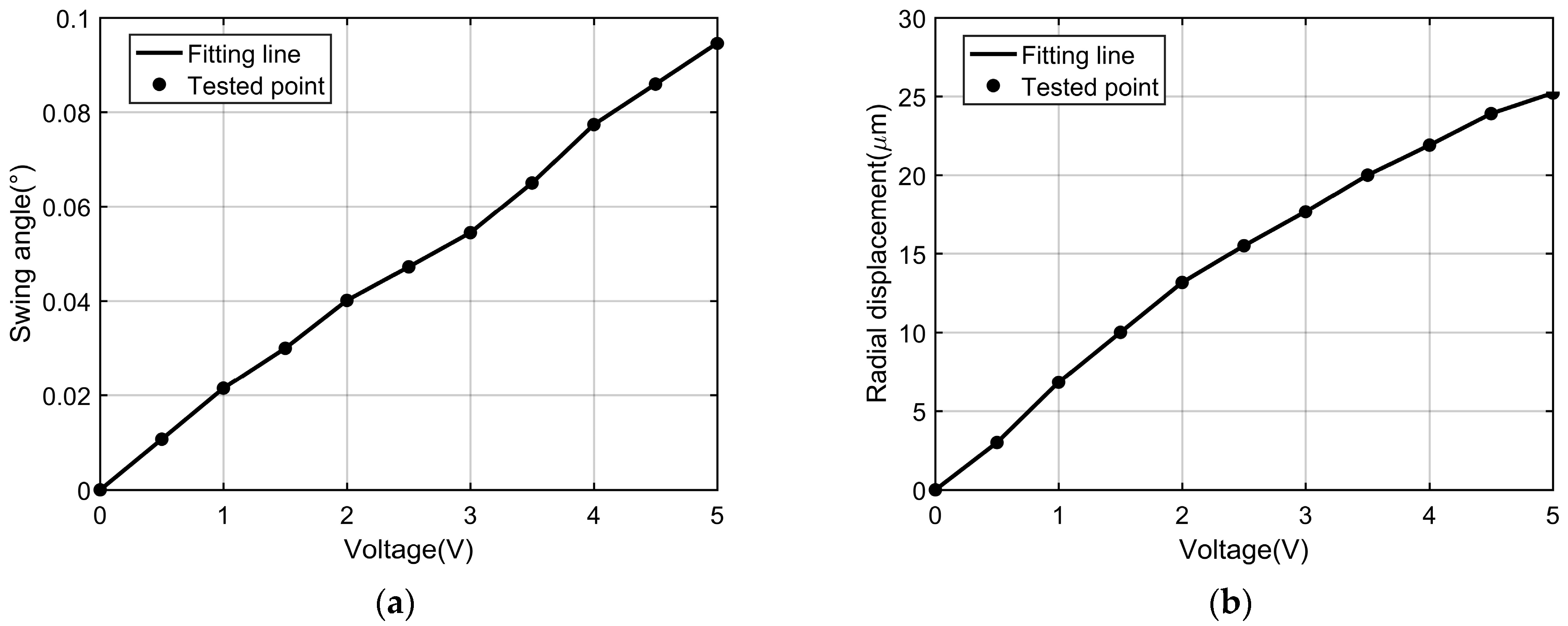
| Piezoelectric Voltage (V) | Control Angle (°) | Control Displacement (μm) |
|---|---|---|
| 0.5 | 0.011 | 3.01 |
| 1 | 0.021 | 6.83 |
| 2 | 0.040 | 13.17 |
Disclaimer/Publisher’s Note: The statements, opinions and data contained in all publications are solely those of the individual author(s) and contributor(s) and not of MDPI and/or the editor(s). MDPI and/or the editor(s) disclaim responsibility for any injury to people or property resulting from any ideas, methods, instructions or products referred to in the content. |
© 2023 by the authors. Licensee MDPI, Basel, Switzerland. This article is an open access article distributed under the terms and conditions of the Creative Commons Attribution (CC BY) license (https://creativecommons.org/licenses/by/4.0/).
Share and Cite
Peng, S.; Qin, X.; Wang, X.; Huang, G.; Xiong, X. Experimental Study of Piezoelectric Control for Changing Tilting Pad Journal Bearing Circumferential Angle and Radial Displacement. Lubricants 2023, 11, 510. https://doi.org/10.3390/lubricants11120510
Peng S, Qin X, Wang X, Huang G, Xiong X. Experimental Study of Piezoelectric Control for Changing Tilting Pad Journal Bearing Circumferential Angle and Radial Displacement. Lubricants. 2023; 11(12):510. https://doi.org/10.3390/lubricants11120510
Chicago/Turabian StylePeng, Shuxia, Xin Qin, Xiaojing Wang, Guangyao Huang, and Xin Xiong. 2023. "Experimental Study of Piezoelectric Control for Changing Tilting Pad Journal Bearing Circumferential Angle and Radial Displacement" Lubricants 11, no. 12: 510. https://doi.org/10.3390/lubricants11120510
APA StylePeng, S., Qin, X., Wang, X., Huang, G., & Xiong, X. (2023). Experimental Study of Piezoelectric Control for Changing Tilting Pad Journal Bearing Circumferential Angle and Radial Displacement. Lubricants, 11(12), 510. https://doi.org/10.3390/lubricants11120510