Abstract
In this paper, a dual membrane restrictor design was proposed to improve the stiffness performance of the compensated hydrostatic bearing. Theoretical models for the proposed dual membrane restrictors were derived. Analysis of these models showed that a high stiffness region could be achieved at the desired loading region through the proper selection of the design parameters. A series of simulations were conducted to study the variations in the design parameters on the stiffness and clearance variations. It was found that the dimensionless membrane stiffness in the inlet restrictor, , was the most dominant parameter for the performance of the compensated bearing system. The main advantages of the proposed dual membrane restrictor are the increase in flexibility by providing high stiffness at the desired loading region; and improving the stiffness performance of the bearing system especially at the desired loading region.
1. Introduction
Compared with typical rolling element bearings, hydrostatic bearings have several advantages such as low straightness ripple, good damping characteristics, low friction, and low wear. With these advantages, hydrostatic bearings were frequently used in high-precision grinding machines to produce high quality components. In the hydrostatic bearing, lubricant pressured by a pumping system was forced into the recess and flowed through the paired surfaces such that the conjugated pair surface could be separated. There are two types of pumping system frequently used in this application, namely, constant pressure type and constant flow type. A constant flow pump was needed for each recess in the constant flow type system, while a constant pressure pump may be used for several recesses in the constant pressure system. This is the reason why the constant pressure-type system is a much more popular one.
For the constant pressure system, restrictors are used to regulate the pressures of the recesses. Related research has been conducted to study and to optimize the performance of hydrostatic system. In general, a hydrostatic bearing with high stiffness is desired, such that the variation of the deflection due to load variation is limited. There are approaches to increase the stiffness of the system such as reducing the nominal bearing clearance, using the opposed-pad design, etc. [1]. Morsi [2] found that with the use of a membrane-type restrictor, the stiffness of the compensated bearing can be improved. Similar conclusions were confirmed by DeGast [3], Cusano [4] and Gohara et al. [5].
Kotilainen [6] indicated that the flow in the membrane-type restrictor is controlled by the deflections of a diaphragm caused by the feedback bearing pressure instead of a spool valve used in many other variable restrictors. A change in the bearing load results in a change in the bearing pressure and a displacement of the diaphragm, thus changing the clearance of the restricted plant and, accordingly, its flow resistance.
Singh [7] and Phalle [8] showed that the static characteristics of multirecess hybrid journal bearings using membrane-type restrictors were affected by the shapes of the recess and bearing. Kang [9,10,11] proposed ways to identify the design parameters of membrane-type restrictors of hydrostatic bearings and proposed a modified prediction model for a membrane restrictor. Bassani [12], Chang [13] and Pan [14] also worked on the parameter design and performance analysis off membrane-type restrictor. Chen et al. [15] performed a fluid–structure interaction analysis of the diaphragm to more acurrately model the behavior of membrane restrictors.
In previous studies [16,17], it was shown that a high-static stiffness bearing system could be achieved if membrane restrictors were properly designed. The dimensionless stiffness of the membrane and the design restriction ratio are the two key parameters for membrane-restrictor design. When , one can theoretically obtain infinite bearing stiffness under some specific loading conditions (i.e., ). It was found theoretically that high bearing stiffness could be achieved within some loading regions (i.e., ). However, it was also found that the system performance was very sensitive to the change of , and the clearance and clearance variation of the bearing was relatively high and such that the stiffness of the bearing was very low when a small load was applied.
A chance for further improvement of the single membrane restrictor design is to add an outlet restrictor between the recess and tank. The outlet restrictor is opened to leak lubricant to the tank to reduce clearance as well as clearance variation in terms of increasing bearing stiffness when the loading is small and closed when the loading is large.
In this paper, the design of the proposed dual membrane restrictor and the model of the bearing system compensated with the proposed dual membrane restrictor was derived first. The analysis for the design parameters to show ways for designing the proposed dual membrane restrictor were then conducted. A series of simulations were conducted to study how variations in the design parameters might affect the performance of the bearing compensated by the proposed dual membrane restrictor. Finally, conclusions are drawn based on the observations of these simulation results.
2. Modelling of the Proposed Dual Membrane Restrictor
The bearing system with a single membrane restrictor and those with the proposed dual membrane restrictor are depicted in Figure 1. The flow resistance of the restrictor was varied due to the deflections of the membrane caused by the pressure difference between the upper surface of the membrane and the lower surface of the membrane. The restricting plane is the inner surface of the protruding portion surrounding the outlet of the restrictor, where the inner radius of the restricting plane is and the outer radius of the restricting plane is as shown in Figure 1a.
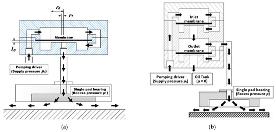
Figure 1.
(a) Bearing compensated with single membrane restrictor. (b) Bearing compensated with proposed dual membrane restrictor. Sketch plots for bearing systems with single membrane restrictor and the proposed dual membrane restrictor.
Some major differences between these two restrictors should be noted. For the dual membrane restrictor, the supplied lubricant is regulated by an inlet membrane first then flows into the bearing recess; at the same time, the recess pressure is also regulated by an outlet membrane which controls the drainage bypassing a partial lubricant to the tank. Therefore, the proposed system has two outlets: one is to the recess of the bearing, another one is going through the outlet membrane then directly draining to the tank.
With the proposed dual restrictor, the lubricant flow rate, , is determined by the supply pressure, , the flow resistance of the inlet membrane restrictor (i.e., the flow resistance of the inlet restricting plane), , the flow resistance of the outlet membrane restrictor (i.e., the flow resistance of the outlet restricting plane), , and the flow resistance of the pad, . The flow rate to the bearing through the inlet membrane restrictor is equivalent to the sum of that flow out of the recess and that flow through the outlet membrane restrictor to the tank, and the following equation could be derived:
where is the recess pressure. The recess’ pressure can also be expressed as
For simplicity, α is defined as the resistance ratio of bearing pad, R/Rr; αi is defined as inlet membrane resistance ratio, Rmi/Rr; and αo is defined as outlet membrane resistance ratio, Rmo/Rr outlet membrane resistance ratio , respectively, where Rr is a constant reference for the flow resistance of the bearing R with a corresponding clearance of hr (the subscript “r” refers to the reference configuration). Then Equation (2) can also be expressed in a dimensionless form as the following.
Based on the cubic law of the flow resistance [12], the flow resistances of the membrane restrictor, Rm, can be expressed as
where is dynamic viscosity of lubricant; as depicted in Figure 1, lo is the assembly clearance between membrane and the restricting plane; x is the membrane deformation; and are the inner and outer radius of the restricting plane in the restrictor; Rma are the restrictor flow resistance when there is no membrane deflection; and is the membrane deformation ratio.
From Equations (3) and (4), the dimensionless deformation–pressure relationship can be derived as:
where the corresponding flow resistance ratio for inlet membrane restrictor and that for outlet membrane restrictor ; Rmia and Rmoa are Rma values for the inlet and outlet membrane restrictor; ξi and ξo are the membrane deformation ratios in the inlet and outlet membrane restrictors, respectively.
The stiffness of the inlet membrane, Km, can be described as
In previous studies [16,17], the dimensionless stiffness of the membrane, , is defined as
where Am is the effective area of the restricting plane in the membrane restrictor [12]:
The pressure ratio, , is mainly determined by the load applied, effective area of the bearing, Ab, and supplied pressure.
For the membrane restrictors in the proposed dual membrane restrictor as shown in Figure 1b, an increased applied load will increase recess pressure and then the inlet membrane deflection will be decreased while the deflection of the outlet membrane will be increased. With constant stiffness, and for the inlet membrane and outlet membrane, the membrane deflection ratio can be described as a function of dimensionless stiffness of the inlet membrane and outlet membrane, :
Then, the dimensionless deformation–pressure relationship shown in Equation (4) can be derived as
However, if the recess pressure ratio is larger than the dimensionless membrane stiffness for the outlet restrictor, , then the exit of the outlet membrane restrictor was closed, the pressure ratio can then be derived as
The relationships between clearance ratio, , and recess pressure ratio (loading) can be derived as:
The dimensionless stiffness of the bearing can then be derived from Equation (13):
The performance of the hydrostatic bearing is highly dependent on the design of the restrictor used. With the derived equations, the effects of the design parameters on these bearing performance measures can be estimated for further analysis.
3. Analysis for Parameters Designs
Theoretically, infinite stiffness for bearings can be achieved by letting the denominator of Equation (15) or (16) be zero. In other words, infinite stiffness for the bearing can be achieved when the following equations are satisfied:
It was indicated that for any recess pressure ratio, , we can find a proper value for the design theoretically such that the bearing system can reach an unlimited stiffness at that value. However, there are several constraints that should also be followed for practical applications.
- 1.
- To maintain the load capacity of the system, the outlet membrane resistor should be closed when the load is high. Therefore, the dimensionless stiffness of the outlet membrane should be restricted by the following equation:
- 2.
- Flow through the inlet membrane restrictor to the recess should be no less than the flow out of the recess through the outlet membrane restrictor.
- 3.
- The bearing stiffness should not be negative to prevent system instability. Therefore,
It should be noted that the term at the left-hand side of Equation (21) is the same as that of Equation (17). It was indicated that the ratio of should be equal to the maximum value of the term at the left-hand side and the corresponding value for the pressure ratio is the loading condition where infinite stiffness for the system appears. In other words, for known dimensionless membrane stiffness of and , a set of corresponding and can be found such that the bearing system can maintain positive stiffness over the entire load region and reach infinite stiffness at .
A series of calculations were conducted to study the effects of membrane stiffness of and on corresponding and . These results provided information for us on how to select these design parameters properly such that a high stiffness hydrostatic system could be designed for some specific loading regions.
Figure 2 shows the effects of dimensionless stiffness of membranes, and , on the corresponding pressure ratio . Examining these results, the following observations can be made:
- 1.
- The corresponding pressure ratio βc where theoretical infinite stiffness can be reached mainly depends on the value chosen of dimensionless outlet membrane . The larger the , the larger the . However, the is always smaller than 0.5.
- 2.
- With a dimensionless membrane stiffness for the inlet restrictor, , of 4/3 and a larger than 1/3, the is maintained at the constant level of 1/3.
- 3.
- The effects of on are less significant. Based on these observations, we found that if high stiffness for a specific loading region is desired, we can identify the corresponding pressure , then the proper and the selection of is less critical.
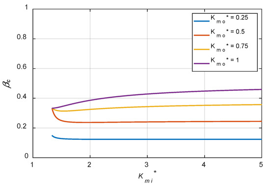
Figure 2.
Effects of membrane stiffness of and on corresponding .
Figure 3 shows the effects of the dimensionless stiffness of membranes, and , on the corresponding . Examining these results, the following observations can be made:
- 1.
- Much larger is preferred when is small and it drastically increases when . When is smaller than 1.5, most of the corresponding ratio is larger than 1. It is indicated that the flow resistance of the outlet membrane without membrane deformation should be larger than that of the inlet membrane without membrane deformation. However, when , the flow resistance of the outlet membrane without membrane deformation should be smaller than that of the inlet membrane without membrane deformation. This indicated that the flow rate of the inlet membrane restrictor should be much larger.
- 2.
- The larger , a larger is preferred. It indicated that if a stiffer membrane was used in the outlet membrane restrictor, the flow resistance of the outlet membrane without membrane deformation should be larger. Based on these observations, it was shown that if a smaller is adopted, the is very sensitive to the selection of . This might increase the difficulty in manufacturing and assembly of these restrictors.
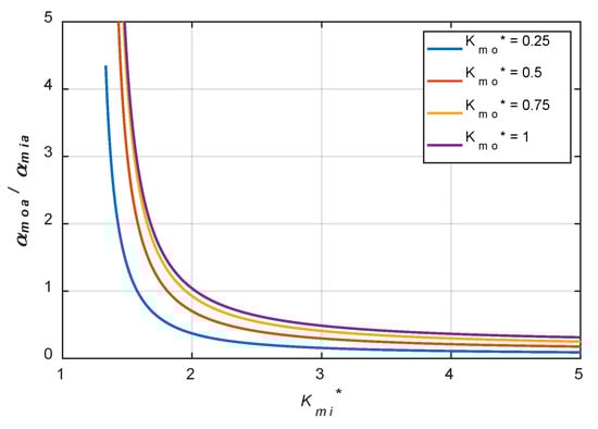
Figure 3.
Effects of membrane stiffness of and on corresponding .
4. Simulations and Discussions
In previous sections, the ways to select the design parameters for the proposed dual membrane restrictors was discussed. It is known that due to manufacturing variations, there are always variations occurring, such that the performance of the system is not what had been designed. Furthermore, the simplifications in modelling would also increase the differences in the performance of the designed systems. However, simulation studies still provide some design guidelines for product design. In this section, a series of simulations were conducted to study how variations in design parameters affect the performance of the system.
Figure 4 is another way to show the relationship between , and . The first set of cases ( > 1.33) studied are also indicated in the figures and parameters for these cases listed in Table 1. For each case, a 10% variation in each design parameter was also simulated.
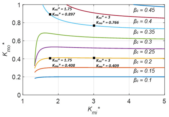
Figure 4.
The relationship between , and .

Table 1.
Design parameters for cases studied ( > 4/3).
Figure 5, Figure 6, Figure 7 and Figure 8 show the effects of parameter variations on the variation of clearance for Case 1 ( = 0.20, = 1.75). After examining all simulation results, the following observations can be made:
- 1.
- Decrease in , or increase in , or increase in αmia, or decrease in αmoa will induce negative stiffness, which might result in system instability.
- 2.
- is the most dominant factor for the performance of the system.
- 3.
- Compared with and , the effects of and αmoa on system performance are more localized and appear around the loading condition corresponding to .
- 4.
- Compared with the bearing system compensated with a single membrane, the proposed dual membrane system with the same and and the optimized and do improve the bearing stiffness.
- 5.
- Even with variation in design parameters, improvement is possible for the bearing system especially when the loading is around the desired .
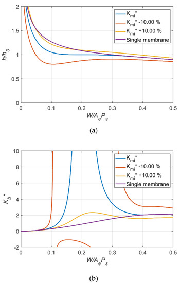
Figure 5.
Effects of variation in dimensionless stiffness of inlet membrane on (a) bearing clearance ratio and (b) dimensionless bearing stiffness. (Case 1: = 0.20, = 1.75).
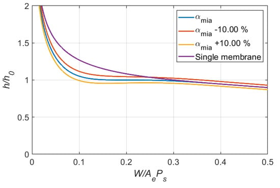
Figure 6.
Effects of variation in dimensionless inlet flow resistance ratio on bearing clearance ratio (Case 1:= 0.20, = 1.75).
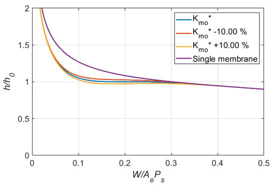
Figure 7.
Effects of variation in dimensionless outlet membrane stiffness on clearance ratio (Case 1:= 0.20, = 1.75).
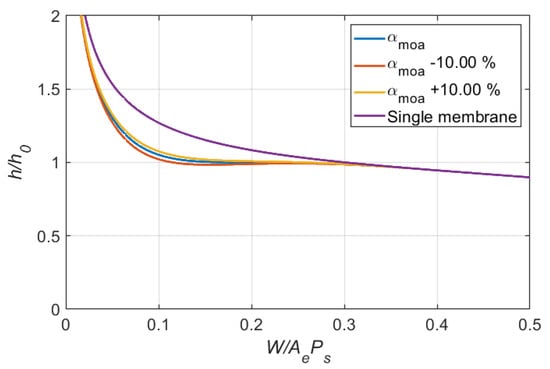
Figure 8.
Effects of variation in dimensionless outlet flow resistance ratio on clearance ratio (Case 1: = 0.20, = 1.75).
Figure 9, Figure 10 and Figure 11 show the effects of variation in on the variation of clearance for the other cases. After examining all simulation results, the following observations can be made:
- 1.
- For a single membrane restrictor, a smaller , a smaller variation in clearance over the loading region ( = 0.2 to 0.8) can be observed.
- 2.
- The working region improved by the optimal design of the dual membrane restrictor is increased as a larger is used.
- 3.
- The effects of variation in dimensionless inlet membrane stiffness, , on the variation of clearance decreased as increased. It is indicated that a larger tolerance is allowable when a larger is used.
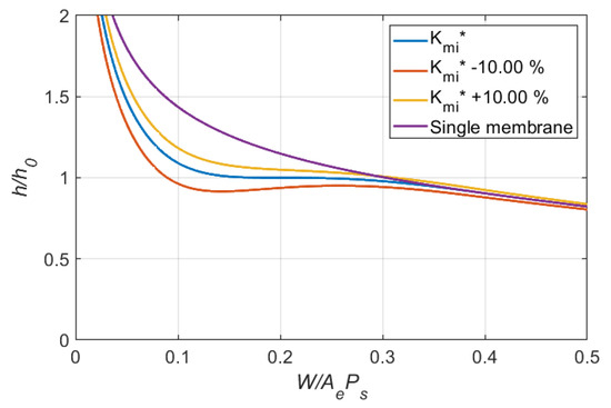
Figure 9.
Effects of variation in dimensionless inlet membrane stiffness on clearance ratio (Case 2: = 0.2, = 3).
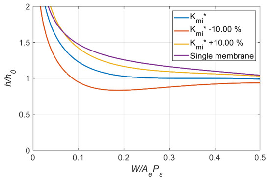
Figure 10.
Effects of variation in dimensionless inlet membrane stiffness on clearance ratio (Case 3: = 0.35, = 1.75).
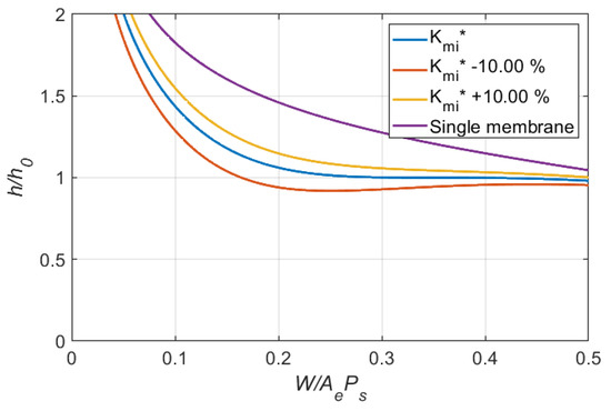
Figure 11.
Effects of variation in dimensionless inlet membrane stiffness on clearance ratio (Case 4: = 0.35, = 3).
Theoretically, infinite stiffness for the single pad hydrostatic bearing can be achieved by using a membrane restrictor with a of 4/3 and of 1/4 when loading appeared at the of 1/3 [15]. However, it was also found that the stiffness of the system was very low when the loading was small. The concept of the dual membrane restrictor was originated to improve the performance of the single membrane restrictor at the low loading region. The parameters for the second set of cases ( = 1.33) studied are listed in Table 2.
Table 2.
Design parameters for cases studied ( = 4/3).
Figure 12 and Figure 13 show the effects of variation in on the variation of clearance and the stiffness for the bearing system for these cases. After examining all simulation results, the following observations can be made:
- 1.
- Two infinite stiffness regions appeared at the loading corresponding to = and = 1/3.
- 2.
- The dual membrane restrictor can provide better performance than a single membrane. However, the clearance levels for these two infinite stiffness loading regions are different and the difference increases as the difference between and 1/3 increases.
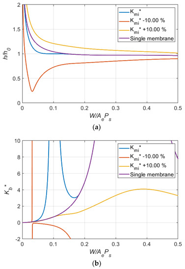
Figure 12.
Effects of variation in dimensionless stiffness of inlet membrane on (a) clearance ratio and (b) dimensionless bearing stiffness (Case 6: = 0.10, = 1.33).
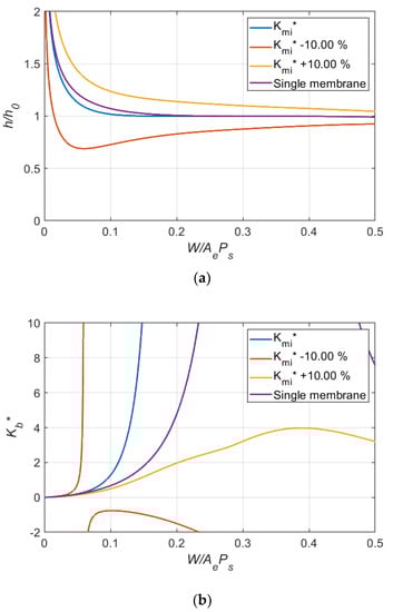
Figure 13.
Effects of variation in dimensionless stiffness of inlet membrane on (a) clearance ratio and (b) dimensionless bearing stiffness (Case 6: = 0.20, = 1.33).
5. Feasibility Tests to Prove the Proposed Concept
In order to prove the concept of the proposed design, feasibility tests were conducted. Figure 14 and Figure 15 show the photo and schematic sketch of the test set-up. In order to prevent the movement of the bearing in the lateral direction, an air bearing was used to hold the horizontal position of the single pad bearing while it provided almost no friction in the vertical direction. The dimensions of all key components are summarized in Table 3. The dimensions were designed such that the dimensionless parameters of the test system were close to the simulated conditions of Case 1.
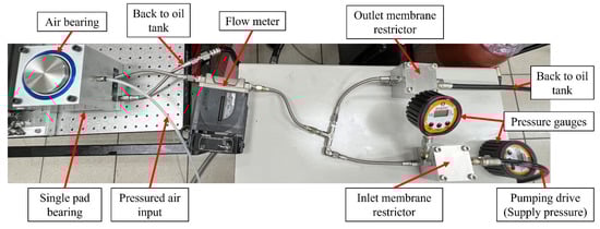
Figure 14.
Photo of the test set-up.
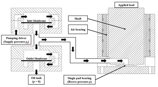
Figure 15.
The schematic sketch of the test set-up.
Table 3.
Parameters used in experiment for case 1: = 0.20, = 1.75.
In these tests, 10 kg iron blocks were added on the top of the bearing one by one to increase the loading on the bearing. The supply pressure, recess pressure, flowing rate of the lubricant measured and the estimated flow resistance of the recess are listed in Table 4. The temperature of the lubricant measured and the estimated viscosity of the lubricant, and hence the film thickness of the bearing under different loading conditions were estimated and are listed in Table 5.
Table 4.
The supply pressure, recess pressure, flow rate of the lubricant measured and the estimated flow resistance of the recess.
Table 5.
The temperature of the lubricant measured, the estimated viscosity of the lubricant and the estimated film thickness of the bearing.
Figure 16 shows the comparison of the simulation and test results for both the single membrane restrictor and the proposed dual membrane restrictor. It was shown that the test results were quite close to the simulation results for bearing compensation with both single membrane and dual membrane restrictors. As expected, the proposed dual membrane restrictor can improve the performance of the bearing in the light loading region.
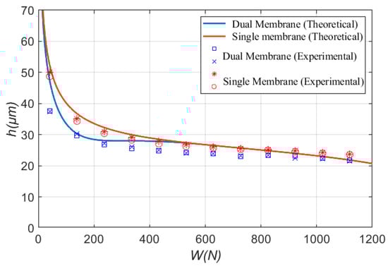
Figure 16.
Experimental results of dual-membrane restrictor comparing with single membrane restrictor (Case 1: = 0.20, = 1.75).
6. Conclusions
In this paper, a dual membrane restrictor design was proposed to improve the stiffness performance of the compensated single pad bearing. The design concept was initiated to improve the performance of a single membrane restrictor in the light loading region. Theoretical models for the proposed dual membrane restrictors were derived. Analysis of these models provided a way to select parameters such that a high stiffness region could be achieved at the desired loading region. A series of simulations were conducted to study the variations in the design parameters on the stiffness and clearance variations. It was found that the dimensionless stiffness of the inlet membrane, , was the most dominant parameter for the performance of the compensated bearing system.
The main advantages of the proposed dual membrane restrictor are the increase in flexibility in providing high stiffness at the desired loading region; and the improvement of the stiffness performance of the bearing system, especially at the desired loading region. In order to prove the concept of the proposed design, a set of experiments were conducted. It was shown that the test results were quite close to the simulation results for bearing compensation with both single membrane and dual membrane restrictors. As expected, the proposed dual membrane restrictor could improve the performance of the bearing in the light loading region.
Author Contributions
Conceptualization and methodology, S.-C.L.; software, Y.-H.L. (Yu-Hsiang Lo), Y.-H.L. (Yu-Hsin Lin); validation, W.-T.T.; resources and writing—review and editing, T.-H.L. All authors have read and agreed to the published version of the manuscript.
Funding
This research was funded by the Ministry of Science and Technology, Taiwan (MOST) grant number (MOST 104-2221-E-007-019) and the Bureau of Energy (Grant No. 109-E0202).
Institutional Review Board Statement
Not applicable.
Informed Consent Statement
Not applicable.
Acknowledgments
The authors thank HIWIN Technologies Co., Ltd. for technical assistance, and financial support, the Ministry of Science and Technology, Taiwan (MOST), for its financial support (MOST 104-2221-E-007-019) as well. In addition, the financial support provided by the Bureau of Energy (Grant No. 109-E0202) is also gratefully acknowledged.
Conflicts of Interest
The authors declare no conflict of interest.
References
- Mohsin, M.E. The use of controlled restrictors for compensating hydrostatic bearings. In Advances in Machine Tool Design and Research; Pergamon: Oxford, UK, 1962; pp. 429–442. [Google Scholar]
- Morsi, S.A. Tapered spool controller for pressurized oil film bearings. Proc. Inst. Mech. Eng. 1969, 184, 387–396. [Google Scholar] [CrossRef]
- DeGast, J.G.C. A new type of controlled restrictor (M.D.R.) for double film hydrostatic bearings and its application to high-precision machine tools. In Advanced in Machine Tool Design and Research; Pergamon Press: Oxford, UK, 1966; pp. 273–298. [Google Scholar]
- Cusano, C. Characteristics of externally pressurized journal bearings with membrance-type variable-flow restrictors as compensating elements. Proc. Inst. Mech. Eng. 1974, 188, 527–536. [Google Scholar]
- Gohara, M.; Somaya, K.; Miyatake, M.; Yoshimoto, S. Static characteristics of a water-lubricated hydrostatic thrust bearing using a membrane restrictor. Tribol. Int. 2014, 75, 111–116. [Google Scholar] [CrossRef]
- Kotilainen, M.S. Design and Manufacturing of Modular Self-Compensating Hydrostatic Journal Bearings. Ph.D. Thesis, Massachusetts Institute of Technology, Cambridge, MA, USA, 2000. [Google Scholar]
- Singh, N.; Sharma, S.C.; Jain, S.C.; Reddy, S.S. Performance of membrane compensated multirecess hydrostatic/hybrid flexible journal bearing system considering various recess shapes. Tribol. Int. 2004, 37, 11–24. [Google Scholar] [CrossRef]
- Phalle, V.M.; Sharma, S.C.; Jain, S.C. Influence of wear on the performance of a 2-lobe multirecess hybrid journal bearing system compensated with membrane restrictor. Tribol. Int. 2011, 44, 380–395. [Google Scholar] [CrossRef]
- Kang, Y.; Shen, P.C.; Chang, Y.P.; Lee, H.H.; Chiang, C.P. Modified predictions of restriction coefficient and flow resistance for membrane-type restrictors in hydrostatic bearing by using regression. Tribol. Int. 2007, 40, 1369–1380. [Google Scholar] [CrossRef]
- Kang, Y.; Chen, C.H.; Lee, H.H.; Hung, Y.H.; Hsiao, S.T. Design for static stiffness of hydrostatic bearings: Single-action variable compensations. Indust. Lubric. Tribol. 2011, 63, 103–118. [Google Scholar] [CrossRef]
- Kang, Y.; Chen, C.H.; Chen, Y.C.; Chang, C.; Hsiao, S.T. Parameter identification for single-action membrane-type restrictors of hydrostatic bearings. Indust. Lubric. Tribol. 2012, 64, 39–53. [Google Scholar] [CrossRef]
- Bassani, R.; Piccigallo, B. Hydrostatic lubrication; Tribology Series; Elsevier: Amsterdam, The Netherlands, 1992; Volume 22, ISBN 044488498X. [Google Scholar]
- Chang, T.Y.; Yang, Y.L.; Liu, F.R.; Lin, S.C. Analysis on Parameters and Design of Membrane-type Restrictor. In Proceedings of the International Conference on Engineering and Natural Science—Summer Session (ICENS—Summer 2016), Kyoto, Japan, 12–14 July 2016; pp. 104–115. [Google Scholar]
- Pan, W.; Zhang, Y.T.; Lu, C.H. An accurate method for determination of the performance characteristics of membrane-type restrictors. Proc. Inst. Mech. Eng. Part J J. Eng. Tribol. 2019, 233, 692–701. [Google Scholar] [CrossRef]
- Chen, D.C.; Chen, M.F.; Pan, C.H.; Pan, J.Y. Study of membrane restrictors in hydrostatic bearing. Adv. Mech. Eng. 2018, 10, 1687814018799604. [Google Scholar] [CrossRef]
- Lai, T.H.; Chang, T.Y.; Yang, Y.L.; Lin, S.C. Parameters design of a membrane-type restrictor with single-pad hydrostatic bearing to achieve high static stiffness. Tribol. Int. 2017, 107, 206–212. [Google Scholar] [CrossRef]
- Lai, T.H.; Lin, S.C. A simulation study for the design of membrane restrictor in an opposed-pad hydrostatic bearing to achieve high static stiffness. Lubricants 2018, 6, 71. [Google Scholar] [CrossRef]
Publisher’s Note: MDPI stays neutral with regard to jurisdictional claims in published maps and institutional affiliations. |
© 2022 by the authors. Licensee MDPI, Basel, Switzerland. This article is an open access article distributed under the terms and conditions of the Creative Commons Attribution (CC BY) license (https://creativecommons.org/licenses/by/4.0/).