1. Introduction
Like all other rotary equipment, gearboxes rely on lubrication. The purpose of lubricating gearboxes is to reduce friction, but there is also a cooling function at the same time to achieve good operation and extend the required service life of the gearbox. Gearbox manufacturers provide basic information regarding the types of lubrication used and the typical lubrication cycle. The transmission’s lubrication system is very important for normal transmission operation. In reality, however, the lubrication requirements of the gearbox depend on the operating conditions, as well as the environmental conditions to which the gearbox is exposed. The quality of the selected oil used to lubricate the transmission is very important. The role of the lubricant is to reduce friction at the points of contact between the two bodies during their relative movement. In order for a lubricant to meet these requirements, it must have the required tribophysical and tribomechanical properties.
Gear lubrication is not a continuous process. It is important that a new lubricating film is created between the tooth flanks each time the gears mesh. The geometric shape of the tooth flanks conditions the rolling and sliding movement of the gears. This causes the gears to operate quite often in the region of mixed friction. This results in damage to the gearbox and an increase in the power loss of the gearbox. Therefore, lubrication is important for the life expectancy of the gears.
Apart from the engine concept, the burden of the reduction of noise and even of engine emissions is placed on the transmission, where the biggest reduction is possible for high-performance gearing systems. This is directly related to transmission efficiency. Nowadays, gearboxes have an efficiency greater than 99%, which means that research into increasing such efficiency greatly reduces the negative effects in transmissions, namely, in the development of high-power applications [
1].
Lubricants, specifically the usage of lubricants, are constrained not only to a particular field but are also used in a wide variety of applications, given the necessity of smooth operation and long service life of used components. The most common applications are in terms of the rotating machines used in the industrial, marine, and automotive fields, where it is essential to lower the effects of power loss to a minimum [
2].
When designing a gearbox, it is especially important to understand the fundamentals of oil behavior, e.g., how oil penetrates the meshing of two gear wheels under dynamic conditions. This is necessary to determine how much oil is used for cooling and how much is used for lubrication purposes. Tribological components, such as gearbox components, bearings, gears, and output components have higher repair or replacement costs [
3]. The downtime of a functioning gearbox can, therefore, take more time in terms of repairs and cause higher financial losses, for example, in wind turbine gearboxes, which makes such repairs more costly [
4]. This means that correctly designed lubrication can prolong the service life of gearbox components, minimize the downtime of repairs, and even save financial resources. The lubrication reliability of bearings is also a very important topic that was studied by Tao et al. [
5]. The study was aimed at time-dependent reliability, considering the randomness of entrainment velocity and normal loads for bearing lubrication. Ye et al. [
6] investigated the reliability of gasoline engine bearings. It was achieved by determining the ratio of film thickness and root mean square roughness. Pei et al. [
7] used the Monte Carlo method to investigate the reliability of gear-pair lubrication. The failure probability of lubrication on different meshing points was obtained.
Dai et al. [
8] performed research where simulations of oil jet lubrication were compared with the empirical data. This research proved that simulation was credible for the prediction of the temperature field for a helical gear pair. Dhar et al. developed a comprehensive, transient, three-dimensional, computational fluid dynamics model of the complete lubrication system of a multicylinder engine, where they used the CFD (Computational Fluid Dynamics) software Simerics-Sys/PumpLinx. The advancement was in the system-level modeling of the engine lubrication system over the one-dimensional models employed, where the predictions compared to the measurements showed positive results [
9]. The research work of Fatourehchi et al., integrated a multi-disciplinary numerical model of gear contacts in a dry-sump transmission, where the proposed model turned out to be capable of simulating a wide range of operational conditions for gearing in transmissions. The generated model was used to evaluate the transient heat transfer and temperature distribution through a gear tooth segment, which was lubricated by an impinging oil jet [
10].
Höhn et al. [
11] stated that the power loss in a gearbox comes from losses in several gearbox components: gears, bearings, seals, and auxiliary losses. Gear and bearing losses can be divided into two categories: no-load and load losses. No-load losses are characterized by the fact that they happen during the rotation of the above-named components, but these components are under no load, i.e., no torque is applied. These losses are mostly related to lubricant viscosity and density. Another factor influencing such losses is the immersion depth of components in the lubricant. However, the casing design, namely, the housing of the gearbox, and the operating conditions have a share in no-load losses. Load-dependent losses can be described as losses that occur during the contact of transmission components. These losses depend heavily on contact stresses, the coefficient of friction, and sliding velocity, which occur in the contact areas of the components. For bearings, the load losses depend on the size and type, rolling and sliding conditions, and, finally, the type of lubricant used [
12]. Deng et al. [
13] researched the churning losses for dip lubrication. In this research, it was stated that churning losses increase with an increase in oil viscosity, immersion depth, and worm meshing angle, where the lubrication was located. The rotational speed and oil recess had a minimal effect on churning losses. However, the immersion depth proved to be key to ensuring that oil particles are in the meshing zone.
Splash lubrication is widely used, mainly in intermediate gearboxes, because of its simplicity and reliability. Significant energy losses often occur during operations in such gearboxes. Most of these losses are dissipated in the form of heat [
14]. Predicting the temperature distribution in transmissions is challenging because the heat convection inside the gearbox is directly determined by the splashing behavior of the lubricant. This splashing behavior can only be determined by experiments or, nowadays, in case-study simulations, but these do not consider the effect of the flow field, which leads to design errors [
15,
16,
17].
In their work aimed at the lubrication of herringbone gears, Xiao et al. [
18] found that the lubrication quality of these gears is closely linked to wheel pinion torque. This torque has a great effect on the fluid’s maximum pressure and can also enable efficient gear lubrication. Wheel speed also affects the minimum film thickness.
Failures are manifested as surface-originated damage, which happens on the surfaces of contacting components, where they can be observed in the form of micro-pitting, spalling, scuffing, excessive abrasive wear, or corrosive wear. Such failures can be detrimental in some cases, i.e., in gearboxes used in wind turbines, or in any high-power gearbox uses. In practice, they are caused by severe operating conditions, such as unsteady or interrupted operation, vibration, component misalignment, and exposure to the elements, but it is mainly due to high load characteristics [
19]. Wieczorek [
20] conducted a study using the method employed by maintenance services for the determination of optimal lubrication conditions. Root cause analysis was performed, which determined the subsequent choice of operating conditions, lubricant type, and other requirements, taking into account the roughness of the gearing surfaces.
Liu et al. [
21] proposed a thermal starved elastohydrodynamic lubrication model. This was to study the effect of starved lubrication on the contact performance of a spur gear pair. Liu et al. [
22] created a numerical elastohydrodynamic lubrication contact model of a coated gear pair. The influence of the ratio between Young’s modulus of the coating and the substrate on contact performance was also studied. Ravivarman et al. [
23] researched a high-contact ratio spur gear drive and the effects of the various parameters on it, wherein optimum bending strength was taken into account. In another work, Fatourehchi et al., presented an integrated numerical method consisting of a tribological heat generation model and a CFD heat dissipation model. The results were compared to analytical methods, but these results were obtained only for a meshed pair of gears, which was stated as a deficiency [
24]. The work of Bonci et al. focused on the analysis of electric axle drives used for electric sports cars, where the aim was to develop an analytical tool that would be used to perform predictive analysis in the concept design phase. The proposed tool was verified by applying it to an industrial context, where the results, in the form of efficiency matrices, showed that the proposed tool perfectly matched the empirical results [
25].
Spiral bevel gears usually operate in heavy-load and heated conditions, where the contact of the machined surfaces happens; this is called transient mixed lubrication. The lubrication and roughness significantly impact the nonlinear dynamic behaviors of gear drives [
26,
27]. Pu et al. [
28] carried out systematic research into mixed-lubrication contact for an entrainment angle. He et al. [
29,
30] considered the influence of rough surface plastic behavior, which led to the proposal of plasto-elastohydrodynamic lubrication models both in point and in line contact. Pei et al. [
31] carried out a study aimed at surface wear and friction in conditions of mixed-lubrication contact. The research was carried out via numerical simulation and experiments. Pu et al. [
32] published a mixed lubrication model for spiral bevel gearing, where the variable entrainment angle and surface-machined roughness of spiral bevel gears were considered. Cao et al. [
33] then researched the influence of contact trajectory on the mixed lubrication, friction, fatigue behaviors, and the flash temperature of spiral bevel gears. These two research projects, unfortunately, did not take into account the squeezing effect of lubricant.
Cao et al. [
34] performed research aimed at an analysis of pitting in spiral bevel gears. During this analysis, the two criteria were adopted for fatigue evaluation. Cracking was then simulated. The critical factor was decided to be the amplitude of shear stress, which results in a lower lifespan in gearing. Croccolo [
35] studied improved lubrication conditions for the increased resistance of tooth flanks.
Diab et al. [
36] found that power losses, which were load-independent, were reduced in gear wheels with smaller sizes of pitch diameters and tooth distance. The reduction of load-independent losses can be achieved by decreasing the width of the gear, which was proven by Seetharaman et al. [
37] in terms of face gear width. Höhn et al. [
38] proved that load-independent losses can be further reduced by reducing the immersion depth of gears, which results in lesser power losses. Spray lubrication, meaning that lubricant is applied to the chosen spot by means of a nozzle, also decreases power losses inside a transmission, as opposed to dip lubrication [
39]. This was proposed by Fondelli et al. [
40], where a liquid jet was used in a high-speed crossflow model; it was also taken into account that the spray-bar system should pass through a rotating airflow before the oil impacted the gearing, while airflow is comparable to pitch velocity. The lubrication and cooling of the gears in spray lubrication are influenced by the position of the spray nozzle. The recommended practice is to aim the stream at the mesh inlet, where better film formation occurs. Spraying onto the mesh outlet yields better cooling characteristics [
41].
Correct lubrication method directly affects the performance of the transmission, mainly the high-speed ones. These losses are caused to a large degree by fluid dynamics, which is tied to the lubrication method. The proper cooling and lubrication of gearing surfaces are key parameters in gearbox failure prevention. This is achieved by applying a proper amount of lubricant, which is best achieved by jet lubrication. This type of lubrication has advantages in terms of less oil being used while securing the correct amount of lubricant on the parts, the temperature of the lubricant is stable, therefore, cooling is also ensured, and there is no excessive quantity of lubricant lowering the performance.
2. Materials and Methods
2.1. Description of the Current State of Lubrication Solutions in Drive Systems
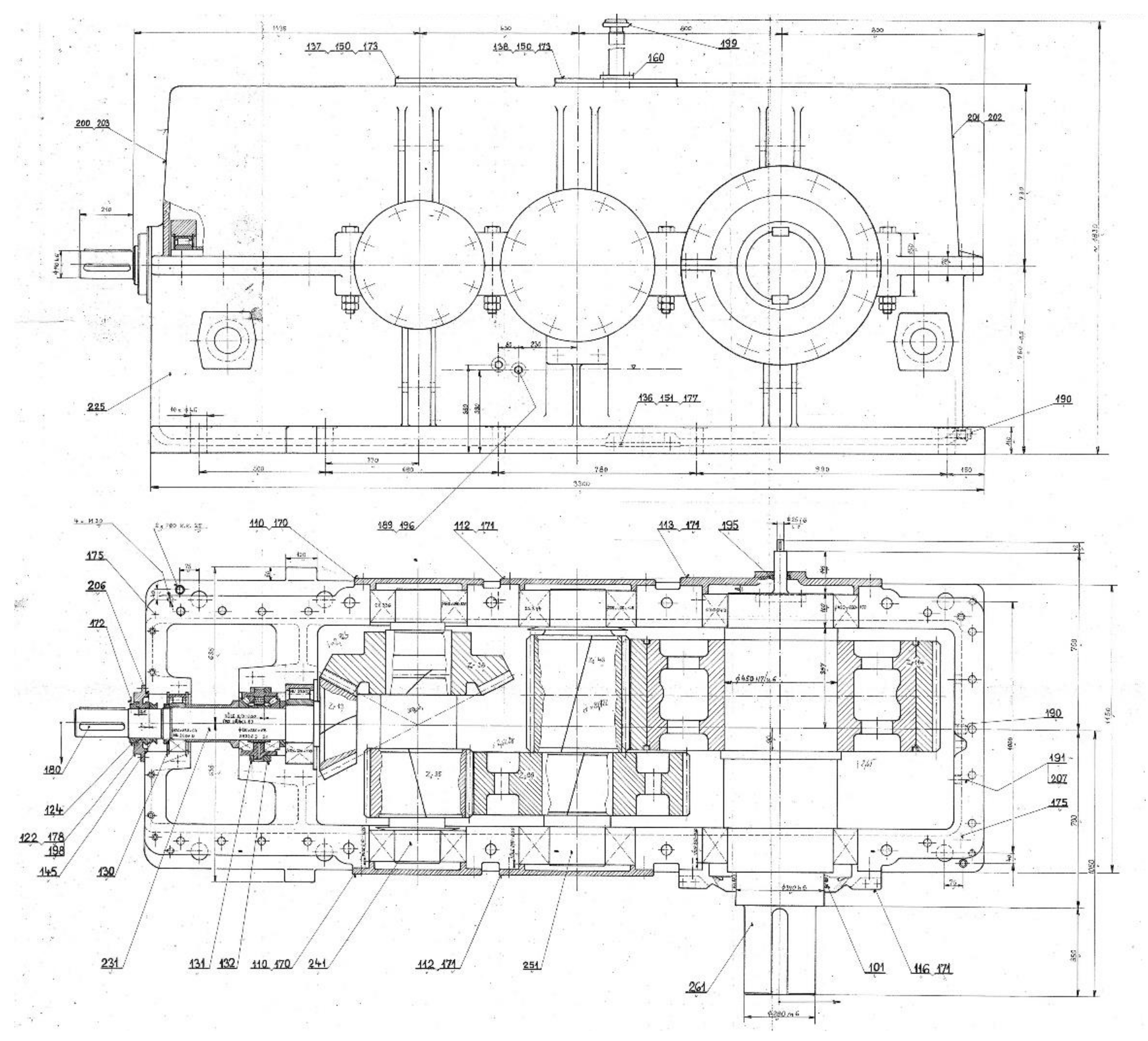
The means of production of transport has experienced dynamic development in recent years. The automotive industry has become the driving force behind the development of the Slovak economy. One of the industries most closely related to the automotive industry is the production of sheet metal. The problem analyzed in this paper arose as the result of a requirement from practice. Specifically, it occurred on a pickling line, where the main task is the treatment of metal surfaces in order to remove all impurities. The supply of this pickling line is by means of two loop carts. These carts are pulled horizontally by steel ropes. The parallel operation of both trolleys is performed on the tracks using a special rope drum. The rope drum is driven via a three-stage gearbox. The first gear stage of the transmission is a spiral bevel gear pair. The second and third gear stages comprise helical gears. The problem was reported to be in the first gear stage, therefore on bevel gears. Bevel gears show a considerable degree of wear. Over the last 10 years, the input bevel pinion, as well as the meshed bevel gear, have been replaced three times. In addition, a separate input shaft, which also includes a bevel pinion, has been changed twice. The schematic for this three-stage helical bevel gearbox is illustrated in
Figure 1.
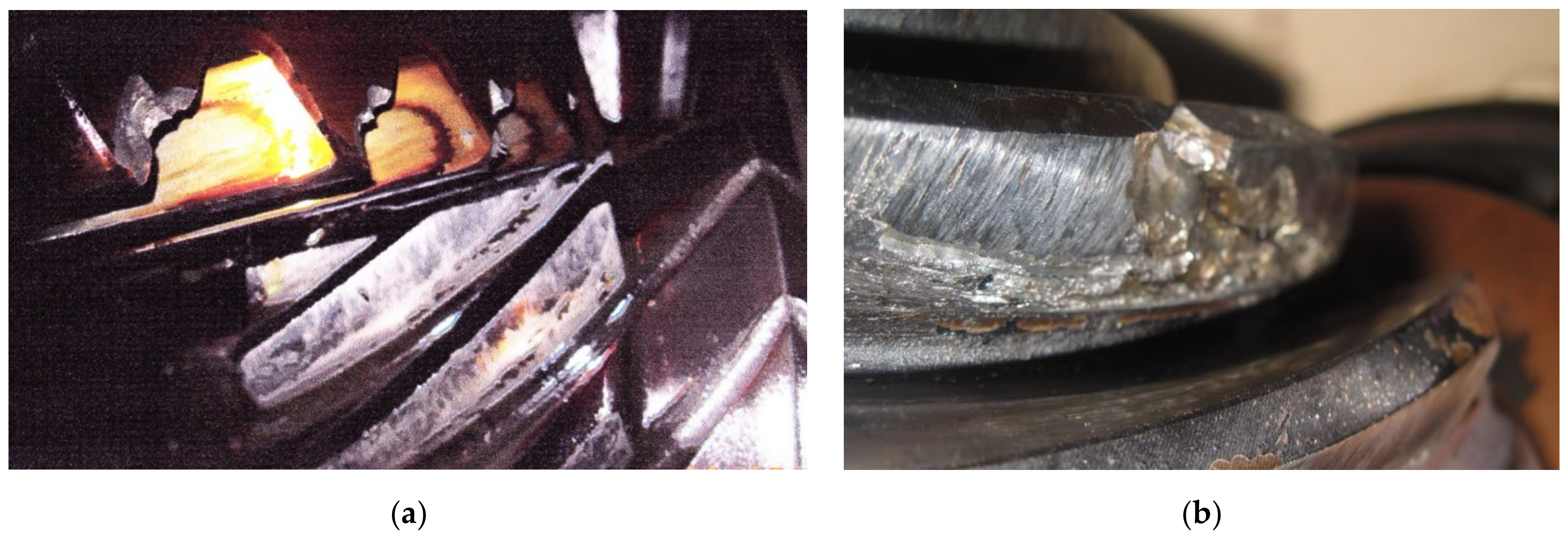
The bevel gear replacement was because of gearing damage. All the teeth of the bevel pinion, as well as the bevel gear, were damaged (
Figure 2). At first, abrasion occurred on the gearing, and later pitting occurred as well. This information was gained using the data from regular inspections. The classification of gear failures according to the causes of failure is of particular importance, as it makes it possible to determine the operating conditions that led to the damage.
The original lubrication was carried out by immersion of the gears in an oil bath, which fills the lower part of the gearbox. Inside the gearbox, 800 L of oil with a viscosity of ν = 44 mm2s−1 at 50 °C were used.
Bevel gears need precise setting-up and an elaborate tune-up before operation. The operator provided data from the regular inspections of the gearbox, as well as the inspection technician’s records of the bevel gear change, which guaranteed this correct tune-up before operation. Based on the gearbox maintenance (service) data, the bevel gear service life was set at 1.9 years. The operator required the gearbox’s service life to be 10 years. Therefore, it was necessary to make changes that had to take into account the preexisting condition of the gearbox, as well as the type of lubricating oil used.
2.2. Parameters of the Helical Bevel Gearbox
The gear ratio of this three-stage helical bevel gearbox is 19.706 and the maximum power is 500 kW (this value is given by the gearbox manufacturer). Because only the first stage of gears was problematic, we focused on its parameters. The first gear stage consists of a spiral bevel gear pair. It is important to realize that the spiral bevel gear pair is preferably used in only one direction of rotation. In the opposite direction of rotation, the transmission can only be loaded with one-third of the power. However, the advantages of this direction is a lower sensitivity to manufacturing inaccuracies and deformations, allowing the operator to achieve higher values of gear ratios in one gear stage. The disadvantage is the expense of machine replacement. The axial forces in this gear pair tend to push both wheels out of meshing. The negative effect of the greater axial forces (as in the case of spur gear wheels) was eliminated in this case by choosing a zero-bevel angle (βm = 0°). This is a beveled gear and pinion pair with Gleason Zerol-type gearing. The number of bevel pinion teeth is z1 = 13, while the number of bevel gear-wheel teeth is z2 = 38. The radial gear module on the outer radial plane mte = 19.394 mm. The surface roughness of the tooth flanks is Ra 0.8.
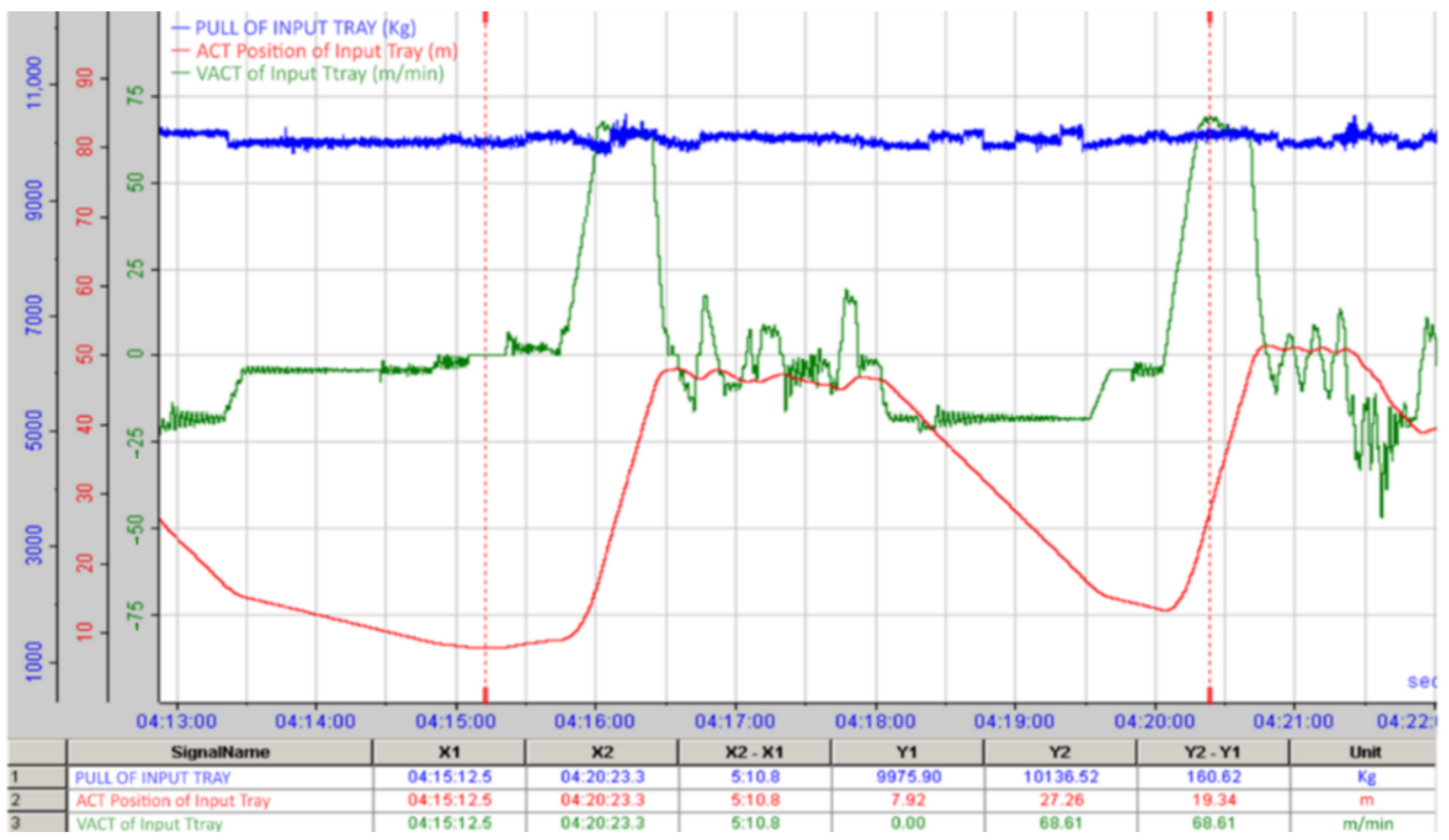
An important step in analyzing the causes of bevel gear damage for the purposes of fault rectification was to determine the operating parameters of the transmission. Based on the provided travel speed of the cart, the traction in the rope, and the position of the cart on the track (
Figure 3), it follows that despite the nominal drive speed, due to the maximum measured travel speed of tray v = 75 m.min
−1, the input drive speed was n
1 = 341 min
−1. The data on the drive of the input tank shows that the power of the drive was P = 410 kW. At a drive power of P = 410 kW and at an input speed n
1 = 341 min
−1, the torque on the input shaft was M
k1 = 11,481.559 Nm.
The second gear-stage consists of a helical gear-pair. In this gear-pair, the number of teeth of the pinion is z3 = 35 and the number of teeth of the meshed gear wheel is z4 = 89. The normalized value of the module in the normal plane is important for the immersion depth of the larger wheel and is mn2 = 10 mm. The third gear-stage is also formed from a pair of helical gears; the number of pinion teeth z5 = 43 and the number of teeth in the paired wheel z6 = 144. The normalized modulus value for this gear pair is mn3 = 14 mm.
Based on the basic parameters of the individual gear stages, input power, and input operating speed, the circumferential speeds for the individual gear wheels were subsequently determined:
Circumferential speeds on the bevel gear pair v1 = v2 = 9.519 m∙s−1;
Circumferential speeds on the second stage of transmission v3 = v4 = 3.822 m∙s−1;
Circumferential speeds on the third stage of transmission v5 = v6 = 1.852 m∙s−1.
From the geometric parameters of the gear pairs, the parameter width of the bevel gearing is required to assess the suitability of the original type of gearbox lubrication. This value b2 = 140 mm.
Due to the frequent failure rate of the first gear stage, a strength check of this bevel gear pair was performed. The bevel pinion is made of W-Nr 1.595 steel, with surface-hardened gearing on the side. The bevel gear is made of W-Nr 1. 7034 steel with surface hardened gearing on the side. A strength check was performed on the basis of the standard used in [
42]. This standard is based on the same principles as the DIN 3990 standard. Working according to this standard, the calculation is based on the control of bending strength and contact stress. The strength analysis was performed, based on the parameters of the bevel gear pair with an adequate method of loading and the required service life. The input data value in the calculation is the service life. A service life of 10 years was required. In this scenario, the bevel gearing is not loaded with a constant load during operation. The load varies, depending on the course of the cart’s linear traveling speed (
Figure 3). It follows from the course of the cart’s speed that when the gear is changed to a reverse direction, an impact load is created on the gearbox, which is reflected in a steep increase in torque and, thus, an increase in the forces exerted on the gearing. Therefore, this calculation is performed for the maximum load (at an input drive speed n
1 = 341 min
−1, drive power P = 410 kW, and torque on the input shaft M
k1 = 11,481.559 Nm). In the first step, a strength check for contact stress was performed, which was determined by the equation:
where index 1 is the bevel pinion, index 2 is the bevel gear, Z
N is the coefficient of contact service life, Z
L is the lubricant coefficient, Z
R is the initial tooth flank roughness coefficient, Z
V is the circumferential speed coefficient, Z
W is the tooth-surface relative hardness coefficient, Z
X is the coefficient of size in contact, σ
H is the Hertz pressure in the rolling point, and σ
Hlim is the fatigue limit in contact. The calculated safety factor for the fatigue damage of the gearing sides in contact has a value of S
H1 = 1.14 for the bevel pinion and a value of S
H2 = 1.27 for the bevel gear wheel. The standard states that S
H ≥ 1.1 to 1.2 must apply to this factor. The gearing complies with the strength check to the contact.
In the second step, a strength check for the bending of the bevel gear pair was performed according to the following formula:
where index 1 is the bevel pinion, index 2 is the bevel gear, Y
R is the tooth-surface hardness coefficient, Y
X is the size coefficient in bending, Y
N is the service life coefficient in bending, Y
δ is the coefficient of notch sensitivity on fatigue, σ
F is the bending stress in the dedendum area, and σ
Flim is the bending fatigue service life for the intended method of loading. The calculated safety factor for fatigue damage of the tooth flanks was S
F1 = 1.56 for the bevel pinion and S
F2 = 1.43 for the bevel gear wheel. In this case, the bevel gear pair satisfied the conditions of the bending strength check, because according to the standard, the value of S
F should be in accordance with the condition S
F ≥ 1.4 to 1.7, which it meets.
Due to the frequent failure of the bevel gear pair and the successful meeting of strength-check parameters, it was decided to examine the lubrication of the gearbox. Insufficient or incorrect lubrication could be the cause of this repeated failure.
2.3. Gear Lubrication by Immersion
Gear lubrication reduces friction on the sides of the gears. This reduces wear and increases gear efficiency and durability. The method of lubrication and the type of oil used depend primarily on the circumferential speed of the gear pitch circles. The rule is that the higher the peripheral speed, the lower the viscosity of the oil that should be used. One frequently used transmission lubrication system is dip lubrication.
Gears with a very low peripheral speed (up to 0.8 m∙s−1) are lubricated with a solid lubricant (grease). This lubricant is applied directly to the gearing by hand. This method is used for gears that are not located within the gearbox.
Gears with a circumferential speed of up to 12 m∙s−1 use the dip lubrication method. The larger meshed gear wheels are immersed in lubricating oil. For multi-stage transmissions, all larger gear wheels in the individual gear stages must be sunk below the oil level. If this is not possible, an auxiliary lubrication wheel can be used.
It is recommended that the depth of immersion of high-speed wheels does not exceed twice the value of the modulus and should not be less than 10 mm deep. As the oil level drops during operation, the immersion depth of the high-speed wheels is up to four times the modulus at rest. At low peripheral speeds up to 1.5 m∙s−1, the immersion depth can be up to 1/6 of the gear pitch circle, but not more than 100 mm. The distance of the submerged addendum circle from the bottom of the gearbox should not be less than 30 to 40 mm. For bevel gears, the immersion depth should be selected so that the gear wheel is immersed in oil over its entire gearing width. it is recommended to use a volume of oil in the range of 0.35 to 0.70 L of oil per 1 kW of transmitted power. At higher speeds, the hydraulic resistance increases, the oil foams and rapidly oxidizes, ages, disrupts lubrication, and limits cooling.
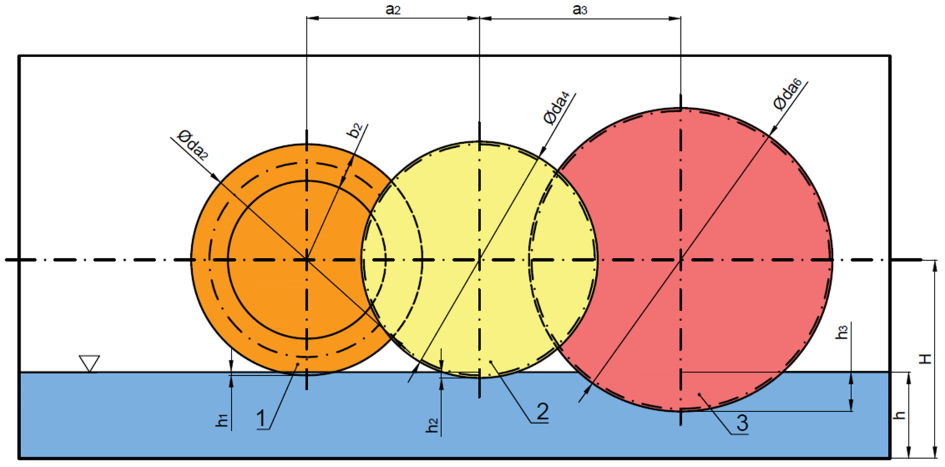
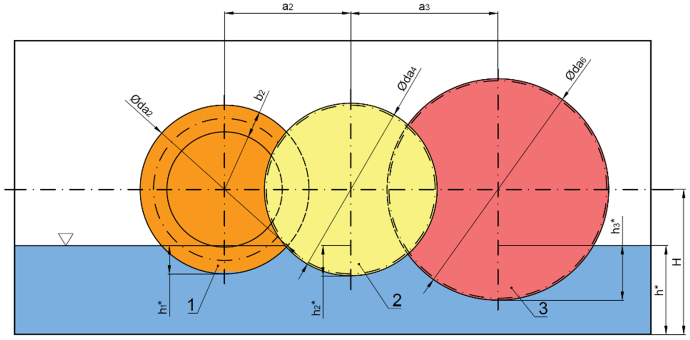
Based on the basic geometric dimensions of the gears and the parameters of the gearbox (
Figure 1), the immersion depth of the individual gears in the oil bath was calculated (see
Figure 4). Parameters a
2 and a
3 are the axis distances for helical gear sets. Item number 1 is the bevel gear wheel, while items 2 and 3 are helical gear wheels. The symbol d
ai represents the diameters of the outside circles of the individual gear wheels.
The first gear-stage bevel gear is submerged below the oil level by h
1 = 12.8 mm. This value represents less than 1/10 (exactly 0.0917) of the gearing width (parameter b
2 in
Figure 4). For proper dip lubrication, this wheel should be immersed across its entire gearing width, i.e., b
2 = 140 mm.
The helical gear of the second gear stage is submerged below the oil level by the value h2 = 22.2 mm. This value represents 2.2 times the modulus value of the gear.
The helical gear of the third gear stage is submerged below the oil level by the value h3 = 150.8 mm. This value represents 10.7 times the modulus value of the gear.
The immersion values of the individual wheels are determined for the gears when at rest. When the transmission is running, the oil level drops. In the first gear-stage lubrication, the bevel gear pair did not meet the requirements for immersion lubrication. This insufficient lubrication has resulted in the frequent gear failures associated with bevel gearing damage.
2.4. Transmission Lubrication Requirements
Circulating lubrication has been proposed for this configuration due to the insufficient initial gear lubrication in the first gear-stage. At the same time, a request was made to change the bearing lubrication used for the bearing of the first countershaft with a bevel gear. The proposal to change the bearing lubrication was based on the data obtained from the maintenance of the gearbox. According to the information provided, the bearings on this shaft were changed much more frequently than would be suggested by the life-cycle calculation. The damage to the bearings indicated insufficient lubrication.
The lubricant in the bearings prevents direct contact between the rolling elements, the raceways, and the cage. This ensures low friction and low wear. The lubricant also performs a protective function against the corrosion of surfaces. Greases are often used to improve seals, and oils are used, e.g., for heat dissipation from the bearing. The type of lubricant and the method of lubrication for the individual bearings of the gear unit depend on the operating conditions. This may also be due to the lubrication of adjacent parts of the device. In this case, previously, the lubrication of the bearings was ensured by oil misting, which was created during the immersed lubrication of the gears. A large volume of oil is not suitable for rolling bearings because the bearings heat up (therefore, for example, if the bearing diameter is larger than the gear wheel diameter, the gearbox is designed to have special rings mounted in front of the bearing).
In general, circulating lubrication is used for peripheral speeds greater than 12 m∙s−1, or in cases where immersion lubrication is not possible or insufficient. In this case, the oil is conveyed into the meshing of the gearing under pressure, by means of nozzles. It is necessary to supply about 0.5 L of oil per minute per 1 cm of gearing length. Generally, if this type of lubrication is used in the gearbox to lubricate the gears, a similar principle is used to lubricate the bearings.
The oil tank forms the lower part of the gearbox. For greater performance and speed, the oil tank is made separately. An oil cleaner or cooler is included in the system. The size of the oil tank, which is constructed separately, must be large enough to give the oil adequate time to cool, stop moving, and eliminate entrained air. The oil level should be between five and ten times the amount of oil flowing through the system per minute.
When designing a circulating lubrication system, it is important to determine the amount of oil required for circulating lubrication from the amount of oil to be drained in the transmission. The heat generated by friction is calculated from the power loss in the individual gear pairs.
3. Design of a Circulating Lubrication System for a Bevel Gear Pair
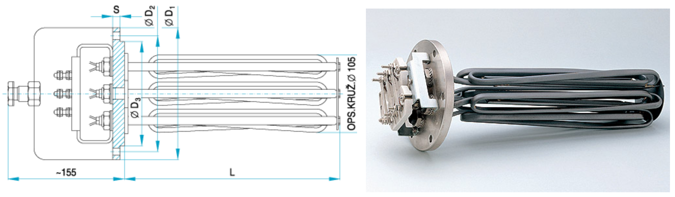
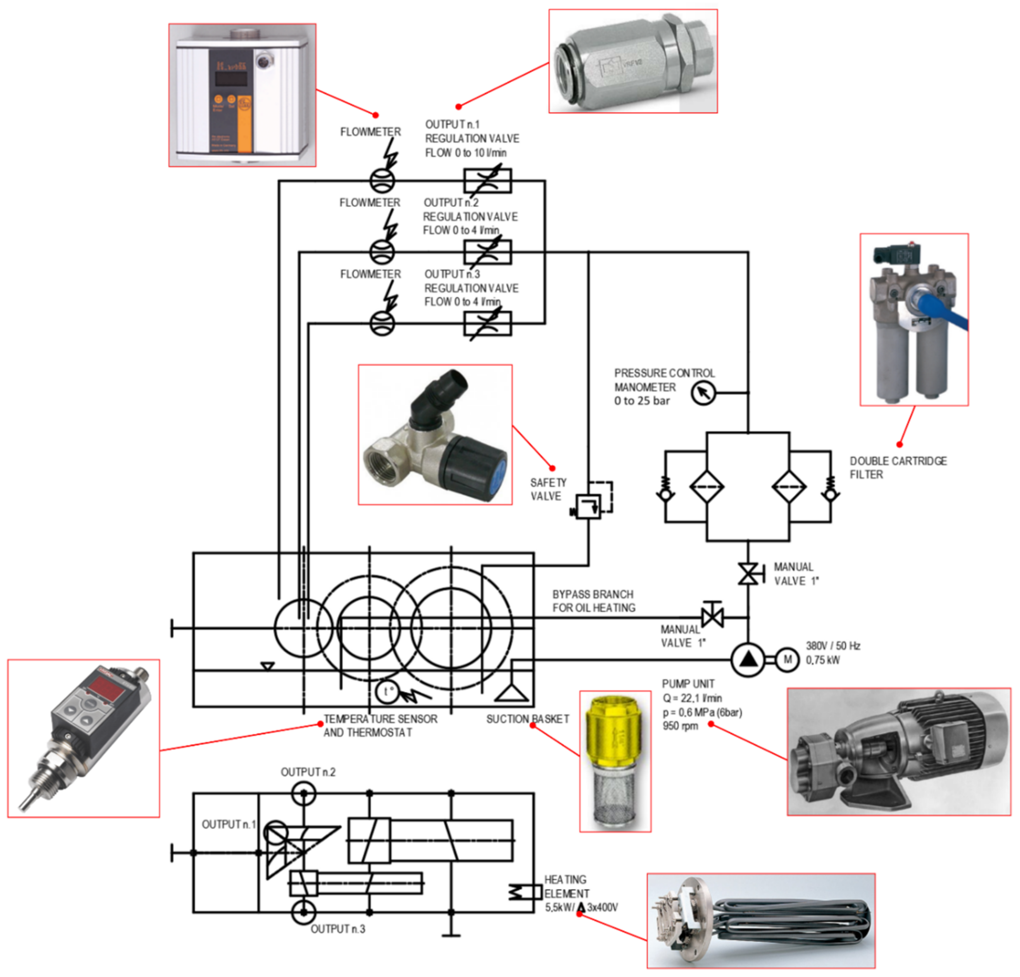
The proposed circulating lubrication system for the first gear-stage of the transmission and for the bearings of the first countershaft consisted of a suction basket, pump unit, filter, control manometer, manual valve, flow meters, and safety valve. The end element on each branch is a spray nozzle. To achieve the required temperature and, thus, the required viscosity of the lubricant, the system includes a heating element, a temperature sensor, and a thermostat. The scheme of the proposed circulating lubrication is shown in
Figure 5.
The lubrication system was designed so that the lower part of the gearbox was used as the oil tank. This means that the option of using a separate oil tank was not chosen, due to the modification of the already existing gearbox on the pickling line, which precluded the possibility of placing this separate tank.
An important element of the circulatory lubrication system is the pump unit. The pump unit consists of a gear monobloc low-pressure pump. The speed of this pump is 960 rpm, at a lubricant spray pressure of 0.5 MPa (5 bar). The manufacturer determines the maximum viscosity of the pumped oil to be 228 mm2∙s−1 at a flow rate Q = 0.22 l∙s−1 (13.2 L∙min−1). The maximum temperature of the pumped oil is 60 °C. A pump with a discharge port clearance (hole diameter) of 1 in (corresponding to 25.4 mm) was selected. The nominal flow is 12 cm3 per revolution. The pump is driven by an electric motor. This electric motor is part of the pump unit. The power of the electric motor is 0.75 kW; it is a three-phase asynchronous electric motor with a short-circuited rotor. It is designed to have a direct connection to the power grid. It has a closed design with its own surface cooling for a voltage of 380 V at 50 Hz. The total weight of the pump unit is 25 kg.
This pump unit pumps the lubricating medium from the gearbox oil bath via the suction basket. The function of the suction basket is to prevent coarse dirt from entering the lubrication circulation system. The clearance (inside diameter) of the suction basket pipe is 1 in (corresponding to 25.4 mm). The suction basket is designed for a pressure of 1 MPa and is generally mounted only in a vertical position.
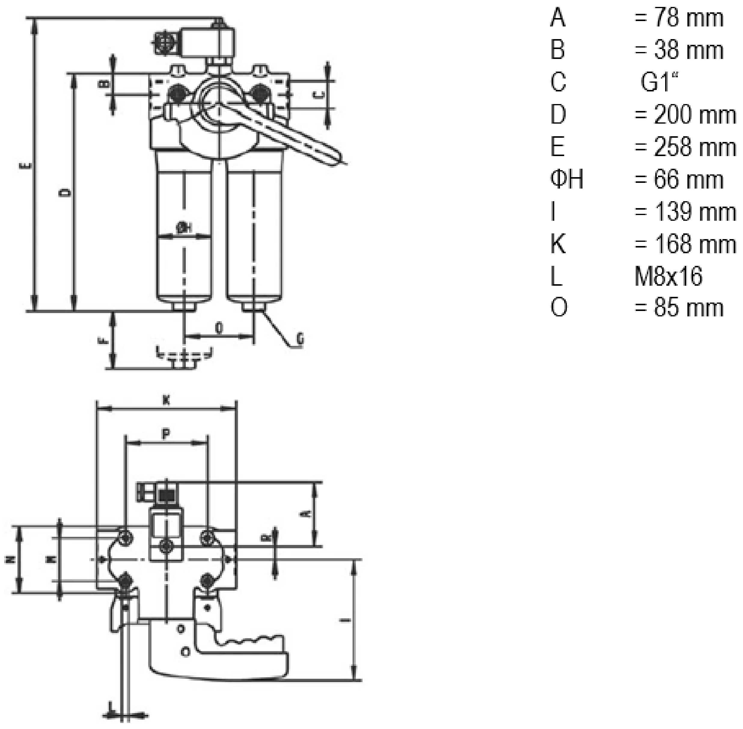
The filter (
Figure 6) is mounted on the discharge point of the pump unit. A double switchable filter with an optical-electrical filter cartridge clogging indicator has been designed for the project. This is a version of a filter with a voltage of 220 V. The pipe clearance is 1 in. The filter operates at a maximum pressure of 20 bar (2.0 MPa) and a maximum flow rate of 50 L.min
−1. Its total weight is 2.6 kg. The filter ensures that the flow is maintained at its outlet. Therefore, it must be flexibly attached and cannot be firmly anchored to the floor. The filter is designed for hydraulic systems that operate non-stop. When signaling that the filter element is clogged, the unit lights up and must be cleaned. The filter consists of two parts, which makes cleaning easier. One part of this filter can be cleaned, while the other part continues to filter the oil.
Another element in the central lubrication system is a control pressure gauge with a range of 0 to 25 bar (0 to 2.5 MPa). This manometer is mounted on the discharge line, to which it is connected by a thread of G 1/4 in, with a manometer diameter of 50 mm.
Because the lubricant needs to be supplied to three parts (for the bevel gears and bearings of the first countershaft), a flow divider is connected to the system. It comprises a divider from one into three branches, with the same flow in each branch that is equal to one-third of the total flow. This divider is mounted on the discharge branch. Due to the fact that the flow of lubricant required for the lubrication of bevel gears (output No. 1 in
Figure 5) is different from the flow required for the lubrication of bearings (outputs No. 2 and No. 3 in
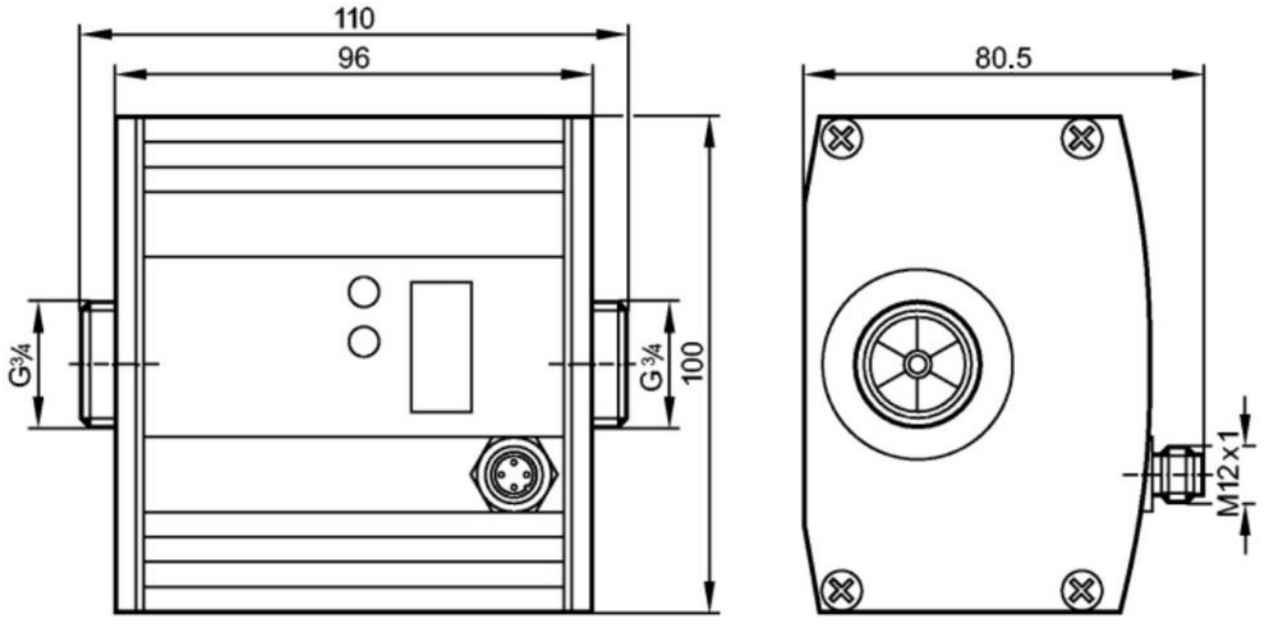
Figure 5), throttles are connected to the system valves. This means that a throttle valve is located in front of the lubricated point (before each outlet), the function of which is to regulate the amount of lubricating oil. To check the flow is correct in the individual outlet branches, lubricant flow sensors are located behind the throttle valves (
Figure 7). The system is designed to use ultrasonic sensors and two programmable switching outputs. The first output is intended for checking the flow of the lubricating medium, with a display of the amount of flow in L.min
−1 and signaling in case of insufficient (zero) flow. The second output is intended for measuring the temperature of the lubricating medium in °C. The connection to the pipe is by means of a G 3/4-inch thread with a flat seal. The sensors are designed for a nominal flow, from 0 up to 50 L∙min
−1.
A safety valve is connected to the system, which is set to a value 1.2 times that of the nominal pressure in the system, i.e., to a value of 6 bar.
Lubrication nozzles are an important element in a central circulating lubrication system. Their task is to evenly disperse the lubricating oil, especially when lubricating the gearing so that there are no shocks during meshing. The correct shape of the nozzles is, therefore, very important. Annular spray nozzles were used to supply the lubricating medium to the bearings, and an oil-spray nozzle was used to supply the lubricating medium to the bevel gear meshing.
A thermostat must be connected to the system. Its task begins with measuring the lubrication at the bottom of the gearbox before starting the lubrication process. An electronic temperature sensor with two switching outputs and one analog with a measuring range from 5 °C to 100 °C was designed. If the oil temperature in the gearbox is below the required operating value before starting, the coil heater is switched on (
Figure 8). Its task is to heat the lubricating medium up to the required temperature. The designed heater was for a voltage Δ3 × 400 V, for a maximum power of 5500 W, and for a maximum volume of the lubricating medium of 800 L. The heater had a permissible operating pressure of 0.6 MPa and its surface temperature was chosen so that no carbonization of the oil occurred.
4. Results and Discussion
4.1. Description of the Operation of the Proposed Lubrication and Required Operating Conditions
Before putting the device into operation, both during the first start-up and after a longer shutdown of the device, it is necessary to activate the thermostat. The thermostat detects the temperature of the lubricating medium. If the temperature is below the required operating value, the heating element (spiral) heats the lubricating medium to the required temperature. When the required lubricating oil temperature is reached, the heating is stopped, and the device (gearbox) is ready for start-up. During the operation of the device, the operating temperature of the lubricating medium is monitored so that in the event of a drop in the lubricant temperature below the set temperature, the heating element is switched on again.
The device is put into operation when the required lubricant temperature is reached by starting (switching on) the pump unit. The pump unit pumps the oil (lubricating medium) from the oil casket at the bottom of the gearbox. A suction basket is used to prevent dirt from entering the lubrication system. This suction basket is located near the output shaft. The pump unit pumps the lubricating medium into the filter. This filter serves to filter fine impurities from the oil and ensures that the flow is maintained at its outlet, where the control manometer is located. The filter is designed for continuous operation, thanks to the possibility of replacing one filter element while the other part of the filter is working. To check the lubricant pressure in the circulatory system, a manometer is located behind the filter. The lubricant is transported through a 1 in (25.5 mm) pipe to the flow divider. The flow divider branches the lubricant supply to the three required outlets: to the bevel gearing and into the two bearings of the first countershaft. The required flow at the outlets is achieved by throttle valves. Ultrasonic flow sensors are used to control the lubricant flow at the outlets. The element on the end of each branch is a spray nozzle. After spraying, the remaining oil then returns to the gearbox, back into circulation.
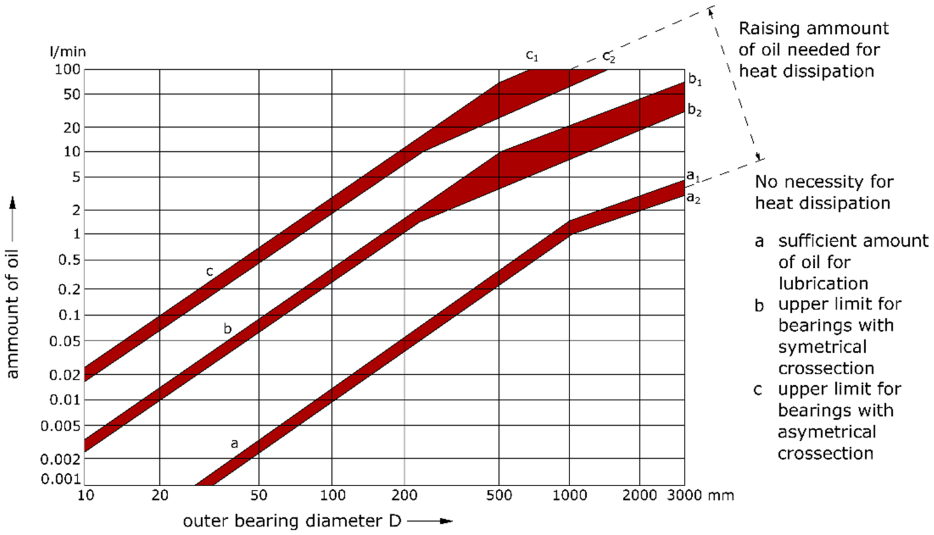
The design establishes the amount of lubricating medium needed—the amount of flow for the lubrication of bearings by the central circulation system was based on the lubrication requirement by the manufacturer catalog of the used bearing. The amount of cycling oil also depends on the operating conditions. An important indicator here was the outer diameter of the bearing used on the first countershaft, i.e., a diameter of 380 mm. Based on the findings reported in [
43], a lubricating flow in the range of from 0.1 L∙min
−1 to 10 L∙min
−1 is required in this case. Higher flow rates are used if the lubricating medium also serves as the cooling medium required for heat dissipation (see
Figure 9). Based on this requirement, a pump unit with a flow rate of Q = 0.22 L∙s
−1 (13.2 L∙min
−1) was selected. The lubricated points (output 1—bevel gear meshing, outputs 2 and 3—bearings) are lubricated with a lower oil flow. The bearing lubrication flow is selected to be 4.4 L∙min
−1, which corresponds to the amount of oil required for bearing lubrication. The resulting flow in the branches will be even lower due to the hydraulic resistances occurring in the branches of the circulating lubrication system. Lubricant flow is inversely proportional to its resistance to movement.
4.2. Assessment of the Gearbox Lubrication Changes
The gearbox was originally designed with immersion gear lubrication. The proposed lubrication changes required modifications and intervention in the design of the gearbox. Changes have been made to the fastenings of the circulation lubrication pipeline and its fastenings to the gearbox body. A method of conducting and connecting central circulation lubrication was proposed.
From the basic panel of central circulation lubrication, a method of guiding the branches to the individual lubrication points was proposed, as well as a method of fixing them. The lubricating oil is conducted in galvanized steel pipes and polyamide hoses. All other accessory components of the proposed lubrication system are standardized. A frame was designed for the lubrication panel, as well as the individual components of the lubrication system, which were made-to-measure for the requirements of the operation. The system is located near the gearbox. The gearbox inspector will thus be able to check the condition of the lubricating medium as well as the functionality of the equipment. If necessary, the operator can add lubricant to the gearbox while the machine is running.
The gearbox area was designed to be used for mounting the heater, as well as for mounting the temperature sensor and thermostat.
In the gears, parts of the tooth flanks are constantly in contact between the pinion and the wheel. The actual contact area is smaller because the contact is of the surfaces of the two meshed teeth and a certain roughness occurs only between the highest bumps of the surfaces. High pressures are exerted on these contact surfaces, and the surface of the material is deformed by compression. As the contact area increases, the temperature and high stresses on the flanks increase. Extensive damage to the gearing can occur in this way. Friction and wear are both reduced by lubrication.
The gear wear in the gearbox is caused by pitting, gearing breakage, or abrasion. All these damage types were found on the bevel gearing under the original lubrication method.
It is important to use a suitable lubricant in the gear unit. Oils that differ in composition, additives, and other properties can be used to lubricate the gears. The lubricating ability is a property that is manifested by the adhesion of the lubricant to the surface of the lubricated part, along with the formation of a continuous lubricating layer and little internal friction. For lubricating oils, this is due to the viscosity. The viscosity of the oil depends on the temperature, pressure, and flow of the lubricant. The higher the viscosity, the greater the value of the fluid friction and the lubricating layer and, at the same time, the greater the load-bearing capacity of the lubricating layer. Viscosity is, therefore, one of the most important properties of a lubricant. The higher the viscosity, the greater the protection against various gear failures. The viscosity must be limited to prevent excessive heat generation and power loss.
Due to the required large quantity of lubricant, the gearbox used the same type of lubricant, even after adjusting the lubrication method, i.e., oil with a viscosity ν = 44 mm2s−1 at 50 °C.
Temperature measurement, whether on the bearing or on the gearing, was performed with a high-speed thermal camera, type FLIR X6530sc, the image frequency of which is in a range up to 3699 Hz, and the standard temperature range is from 5 °C to 150 °C; however, it can reach temperatures up to 2500 °C. The measurement inaccuracy is ±1 °C or ±1% of the measurement. The camera is paired with FLIR ResearchIR software, manufactured by Teledyne FLIR company (Wilsonville, OR, USA). For this measurement, the upper part of the gearbox was replaced by a part made from a transparent material. This transparent upper part was necessary for and gave the possibility of taking readings of the temperature of gearing as well as of the bearings during operation.
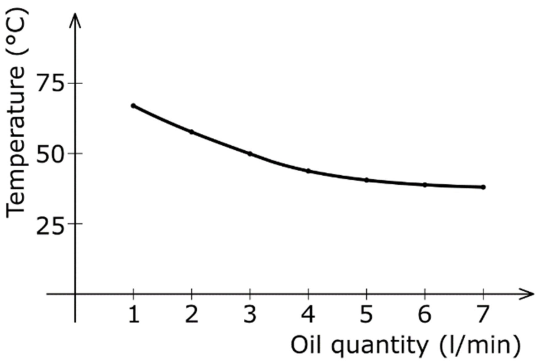
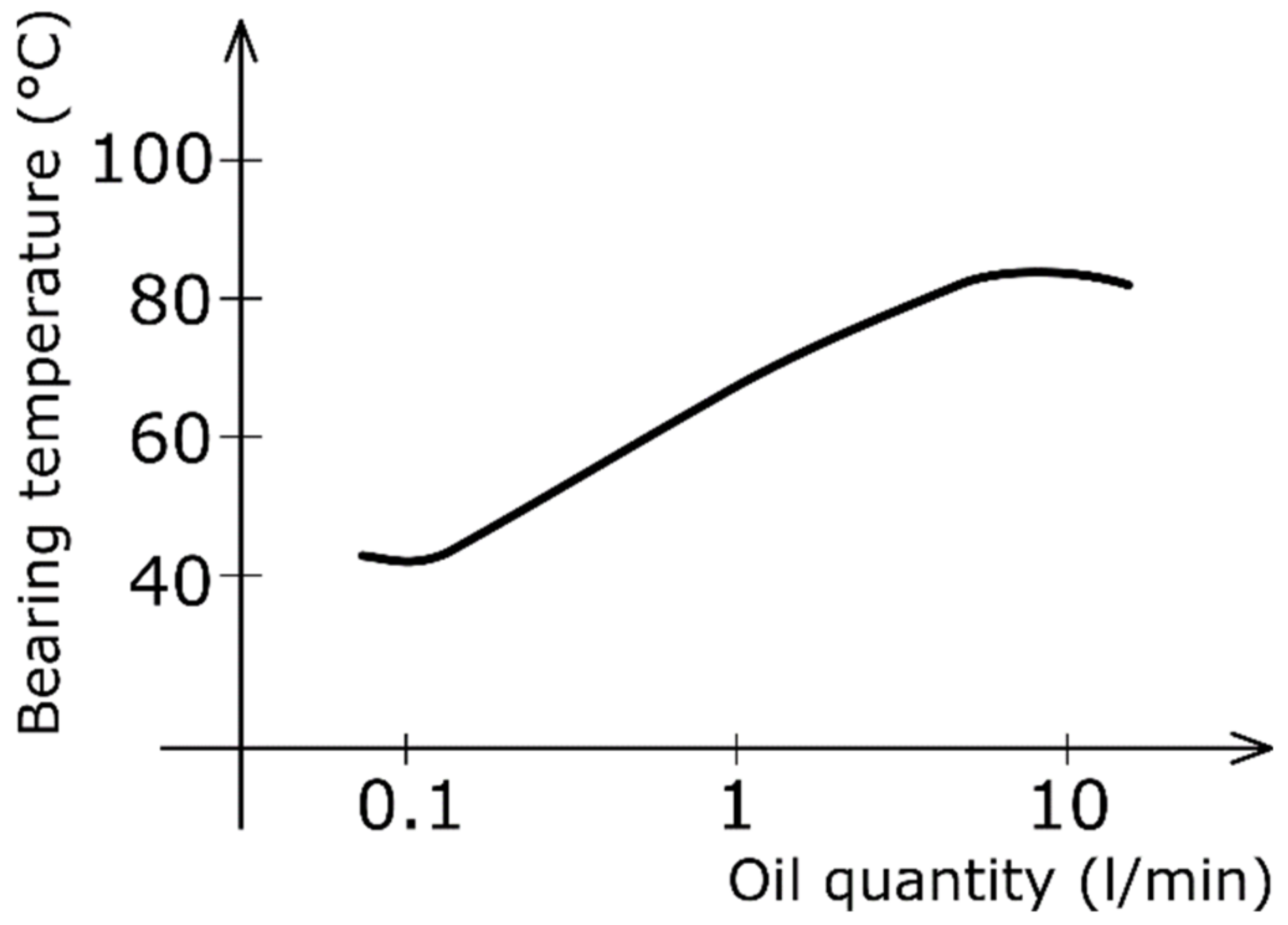
Figure 10 shows the measurement of the surface temperature of the bevel gears as a function of the oil quantity (flow) used to lubricate the gears after adjusting the lubrication method. The measurement took place during operation. Individual series of measurements were performed during different lubricant flows. The graph shows the average value of the unmeasured tooth surface temperature for each lubricant flow value.
Based on these results, a flow rate was selected for the lubrication of a bevel gear with a capacity of 5 L∙min−1. Measurements showed that with a further increase in flow, the gearing surface temperature decreased only minimally.
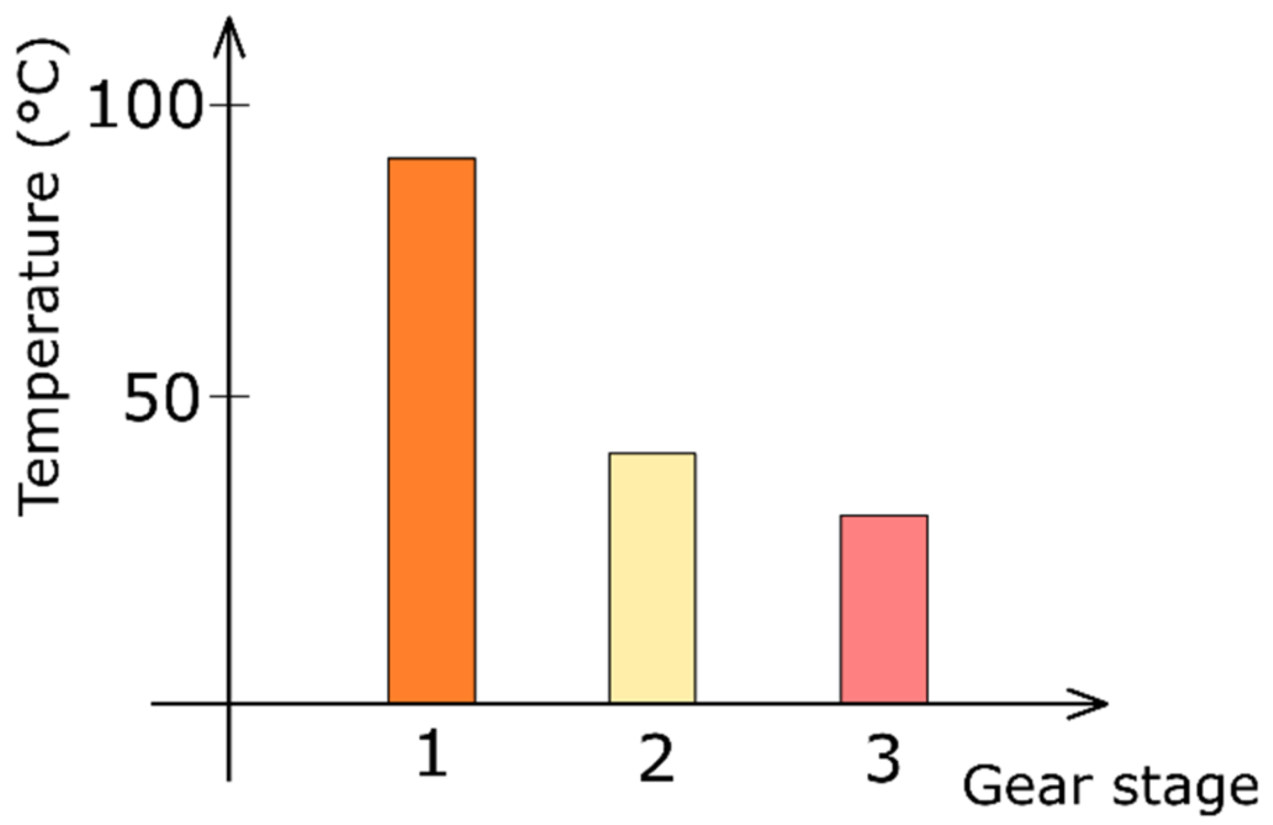
At the same time, these results were compared with the measurement of the surface tooth temperature of the bevel gearing under the original lubrication method, i.e., dip lubrication. In this case, measurements were made on the individual gear stages and the mean value of these measurements is recorded in
Figure 11. The temperature of the tooth surface for the bevel gear pair is double the measured temperature of the tooth surface for the second gear-stage. The temperature of the tooth surface of the third-stage helical gear wheel pair is the lowest. The figure shows that the immersion lubrication for the second and third stages is sufficient.
When changing the lubrication of the bearings of the first countershaft, the optimal quantity of lubricant (flow) was investigated, based on the measured bearing temperature (
Figure 12). The measurement took place during operation. Based on this measurement, the oil flow selected when lubricating the bearings had a value of 0.1 L∙min
−1.
The bearings must be lubricated as soon as the gear unit is started. Therefore, when using this circulation lubrication method, the pump must be switched on before starting the gear unit. At the same time, the entire lubrication system is started only when the required oil temperature is reached, which must not fall below 20 °C when starting.
During the starting of the additional circulation lubrication of the gearbox, the change in oil viscosity during long-term operation was investigated. The two-year measurement results of this modified lubrication system show that the oil retains its viscosity and stability even during long-term operation.
The primary consideration was to improve the lubrication of the first gear-stage (bevel gear) by increasing the level of lubricating medium (oil). The oil level was raised to h
1* = 140.8 mm, so that the bevel gear wheel, which is located on the first countershaft, is immersed across the entire width of the gearing b
2 = 140 mm (
Figure 13). The immersion depth of the bevel gear meets the specification for immersion conditions in the lubricant over the entire width of the gearing. The immersion depth of the second gear-stage, i.e., the helical gear, has increased to h
2* = 150.2 mm, which corresponds to 15 times the value of the modulus. The immersion depth of the third gear-stage, i.e., the helical gear, increased to a value of h
3* = 278.8 mm, which corresponds to a value that is 19.9 times the value of the modulus.
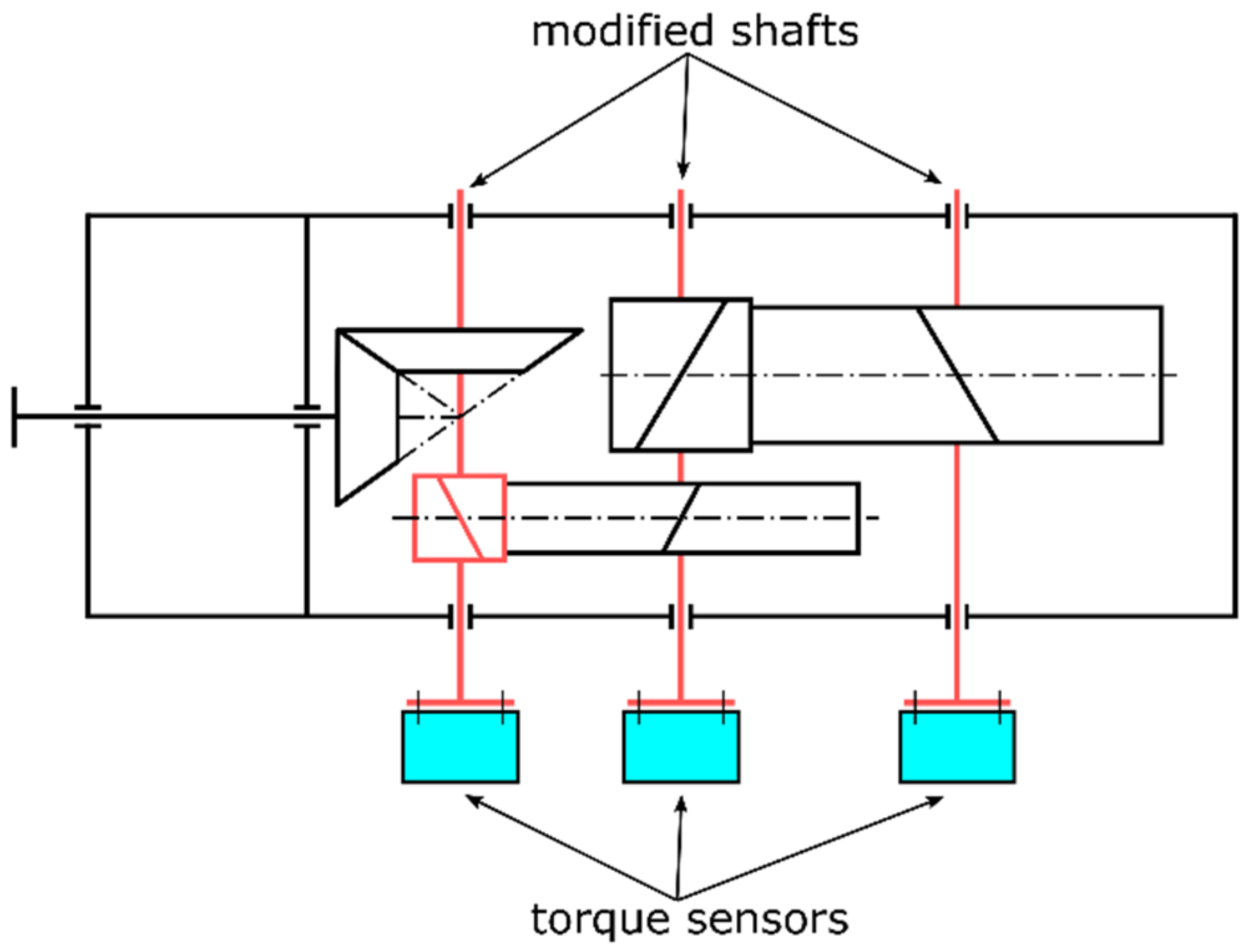
The torque measurement was performed during the operation of the pickling line. New countershafts were designed and manufactured for measurement purposes. Their shape has been designed to recreate the cylindrical ends of these countershafts, which ended with flanges for the mounting purposes of the torque sensor. A torque-measuring flange for rotating shafts, type XtreMAX 300 kNm, with accessories was used as a torque sensor. This torque sensor is designed to measure torque up to 300,000 Nm. Its operating temperature range is from −10 to 70 °C. The manufacturer states a measurement inaccuracy of ±0.1%.
Figure 14 shows a diagram for an experimental setup.
During such immersion lubrication, a decrease in torque was recorded in the second and third gear-stages. A more significant negative effect was recorded in the decrease in the output shaft torque. The torque was measured during transmission operation with a torque sensor.
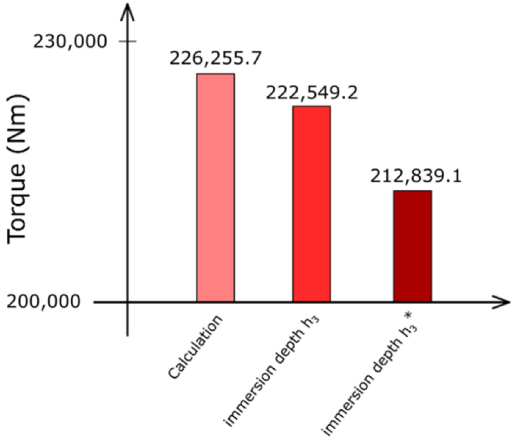
Figure 15 shows the change in torque on the output shaft at the set immersion depth during the original lubrication (
Figure 4) and when the oil level, according to
Figure 13, increases compared to the calculated value. Due to the increase in resistance caused by the increased immersion of the gear wheel in the oil, the torque on the output shaft decreased by approximately 5.9%.
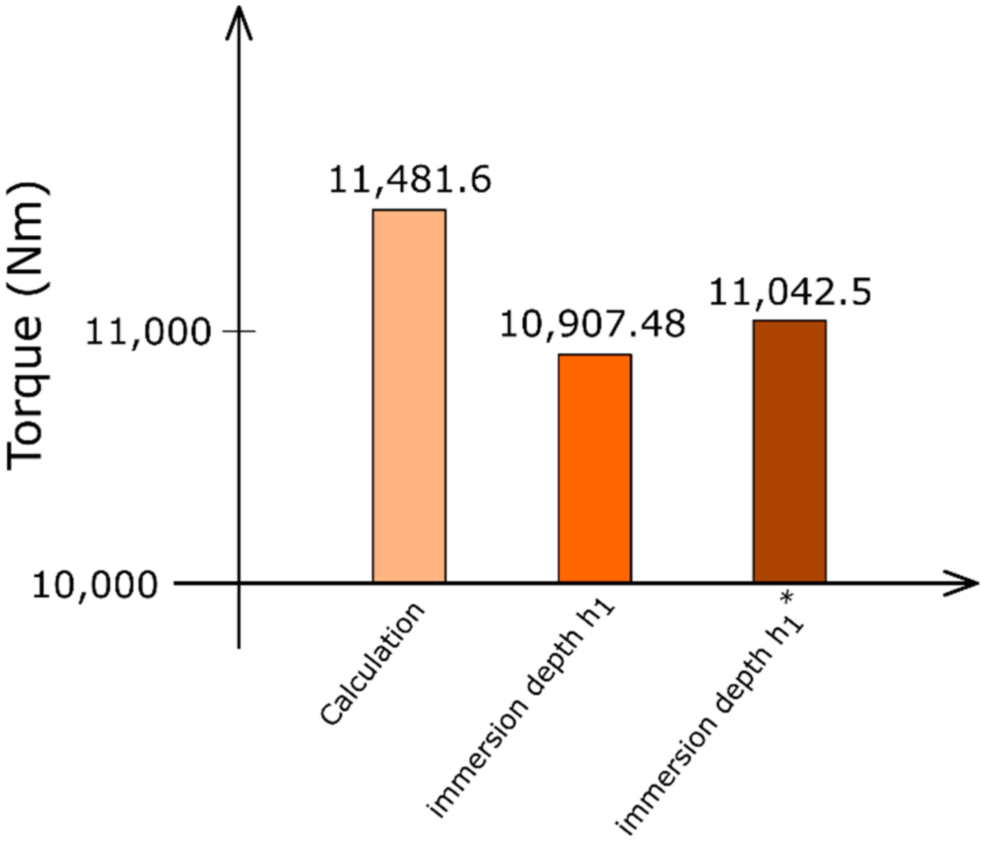
Figure 16 shows the torque change on the first countershaft. At the original oil level, the torque decreased by approximately 5%, while, as the immersion depth increased, it decreased by 3.8%.
This method of increasing the level of the lubricating medium was unsatisfactory. The efficiency decreased during gearbox operation. Due to the increase in resistance caused by increased immersion of the wheel in the oil in the second and third gear-stages, the torque decreases, which results in a decrease in power and, thus, a decrease in efficiency. Another disadvantage was the foaming of the lubricant. Due to the increase in the oil level, the outer ring of the bearing on the output shaft was also immersed in the oil bath. Lubricant leaked from the gearbox, which was not structurally adapted to be sealed.

