Article

Study on Friction Characteristics of Slipper Pair of Large Displacement High-Pressure Piston Pump

1
Technical Center, China Railway Engineering Equipment Group Co., Ltd., Zhengzhou 450016, China
2
College of Mechanical Engineering, Zhejiang University, Hangzhou 310063, China
3
School of Mechanical Electronic & Information Engineering, China University of Mining and Technology-Beijing, Beijing 100083, China
4
School of Mechatronics Engineering, Henan University of Science and Technology, Luoyang 471003, China
*
Author to whom correspondence should be addressed.
Lubricants 2022, 10(12), 363; https://doi.org/10.3390/lubricants10120363
Submission received: 7 November 2022 / Revised: 4 December 2022 / Accepted: 13 December 2022 / Published: 15 December 2022

Abstract

:
The reference value of the oil film thickness and friction coefficient of the slipper pair is critical to the development of the piston pump, especially for 750 mL/r displacement piston pumps. To explore the computing method and range of the reference value mentioned applicable to 750 mL/r displacement piston pumps, this study aims to propose the modified calculation model of the oil film thickness based on the real clearance flowrate and obtain the value range of the friction coefficient of the slipper pair. Through the friction test of the slipper pair, the mean deviation ratio of the oil film thickness between the modified value, theoretical value, and the measured value was calculated and compared, respectively. The variation law of the friction under the influence of different speeds and working pressures was analyzed. Finally, the range of the equivalent friction coefficient with the upper and lower limit surfaces was obtained. The results show that the mean deviation ratio between the modified oil film thickness value and the measured value is mainly within 6%, while that of the theoretical method is mainly from 6% to 8%, and the mean of the difference between the two deviation ratios is about 3%, verifying the feasibility of the modified model used for the calculation of the reference value. Meanwhile, the value of the equivalent friction coefficient fluctuates in the range of 0.006–0.018, which is affected more significantly by the working pressure than the speed, suggesting that the working pressure can be given priority as the design basis of the friction coefficient for 750 mL/r displacement piston pumps.

1. Introduction

Piston pumps have been widely used in all walks of life. According to the displacement and pressure, they can be divided into a variety of series, and the pumps with small displacement (≤500 mL/r) and low-medium pressure (≤25 MPa) are most frequently used [1,2,3]. With the rapid development of shield, shipbuilding, military, and other special industries, the demand for large displacement high-pressure (especially displacement ≥ 750 mL/r, pressure ≥ 35 MPa) piston pumps is increasing [4,5]. However, due to the design problems of friction pairs, the development of this type of pump has been seriously restricted in the enterprise.
Among the problems mentioned above, the design problems of oil film thickness and friction coefficient are the most prominent. In terms of the oil film thickness, the accuracy of existing theoretical calculations under 750 mL/r displacement conditions is not clear since it can be affected by the increasing leakage with the increase of displacement, so the theoretical calculation method needs to be verified or modified. Similarly, for the friction coefficient, this value is designed by referring to the empirical value of small displacement pumps normally, lacking selection basis and relevant test verification under 750 mL/r displacement conditions [6]. The selection of the above two values directly affects the friction pair’s design quality and determines the pump development’s success or failure. Therefore, it is crucial to explore the applicability of the existing theory under 750 mL/r displacement conditions.
A large number of researchers have conducted a series of studies on the oil film characteristics, friction force, and leakage of the friction pairs. However, most of them are aimed at small displacement low–medium pressure working conditions, or not for specific working conditions, while studies on 750 mL/r displacement working conditions are rare [7]. For example, in the 1980s and 1990s, Hooke et al. [8,9] studied the influence of overturning torque on the friction characteristics of the slipper pairs under actual working conditions. Koc et al. [10,11] built a test bench that can detect the performance, oil film thickness, and low-medium pressure leakage loss of the piston pump slipper pair. Harris et al. [12] used the dynamic simulation software Bathfp to simulate, analyze the attitude of the slipper, and obtain the maximum and minimum oil film thickness curves of the slipper pair during the operation cycle of the piston pump. Zhao et al. [13] proposed a modeling method of the oil film thickness field and established the force model of the slipper pair and the numerical solution model of oil film lubrication of digital valve distribution axial piston pump, which solved the influence of rotation speed and inclination angle of the slipper pair on the characteristics of oil film lubrication. Besides, some scholars studied the friction characteristics of the slipper pair under higher operating conditions and carried out corresponding tests. Sun et al. [14] studied the variation of the oil film thickness varying with pressure and speed, the maximum values of which can reach 30 MPa and 3500 r/min separately, considering the thermal wedge force. Shen et al. [15] conducted further research on oil film thickness analysis considering both the thermal wedge force and the dynamic pressure effect on the slipper pair with a displacement of 190 mL/r. He et al. [16] and Liu et al. [17] established the mathematical model of oil film dynamic change of the slipper pair and carried out the simulation analysis in the condition of 35 MPa and 3000 r/min [17]. Besides, Tang et al. [18] discussed the influence factors of slipper pair clearance leakage, oil film thickness, and friction torque, and the results were verified and analyzed by experiment using the pump with a displacement of 190 mL/r. Lin et al. [19] elaborated on the influence of the speed, load pressure, and oil viscosity on the dynamics of the slipper. Kazama et al. [20] studied the lubrication characteristics of the friction pair of the piston pump and found the change rule of oil film thickness, temperature, and energy loss of the friction pair changed with the speed. Xu et al. [2] presented a novel performance model of the losses of a pump, which allows an explicit insight into the losses of various friction pairs of pumps. Ivantysynova et al. [21,22] developed a piston pair test bench, which can measure the oil film temperature and pressure distribution in the piston pair, and the lubrication state, power loss, and leakage of the piston pair can be analyzed through the test results. Tang et al. [23] proposed a new TEHD lubrication model for the axial piston pump’s slipper pair and discussed the slipper pair’s deformation, oil film thickness, and pressure distribution. The results show that the oil film thickness is consistent with the measured value. Wang et al. [24] presented a steady-state elastohydrodynamic lubrication model for the friction pair of the axial piston pump and investigated the oil film thickness, pressure, viscosity of the friction pair, and the variations in leakage and friction coefficients. The results show that the deformation caused by oil film pressure greatly influences the model leakage and friction coefficient. Hu et al. [25] conducted a study of theoretical and experimental on the dynamic pressure bearing law of the slipper pair of piston pumps and established the friction dynamics model of the slipper pair. The results show that there was always a wedge-shaped convergence gap between the slipper and swashplate, which was profit to the formation of an oil film of the slipper pair. To improve the service life and total efficiency of the piston pumps, Xu et al. [26] investigated the change in the coefficient of friction of the pin–disc via a friction/wear experiment, and the results show that higher rotational speed results in a smaller coefficient of friction, whereas a greater load results in a higher coefficient of friction, using lubricating oil can significantly reduce the coefficient of friction, and the effect of rotational speed on the coefficient of friction is greater than the effect of load.
The above experimental research is of great significance for the large displacement high-pressure piston pump. However, due to the more complex working conditions of large displacement and high pressure, the test is still difficult. At present, the research on the dynamic characteristics of the slipper pair of the large displacement high-pressure piston pump mainly adopts the numerical simulation method [7]. Li [27] simulated the oil film characteristics of the slipper pair of the JBP-40 piston pump and obtained the variation rule of the oil film thickness under different working conditions and different structural dimensions of the slipper pair. Tang et al. [28] established a fully coupled thermos-mechanical model of the slipper pair considering friction heat generation. They studied the influence of the structural parameters of a slipper on oil film thickness, leakage rate, and other properties under different working conditions. Xu et al. [29] established the simulation model of the oil film coupling relationship of the slipper pair by MATLAB programming and proposed a new method to study the dynamic characteristics of the oil film of the slipper pair. Ma et al. [30] presented one analysis method of the oil film characteristics of slipper pair, based on the hydraulic dynamic lubrication theory and Reynolds equation, and the availability and results in precision were validated by comparison between serval numerical results of leakage through slipper swash plate pair. Tang et al. [31] investigated and optimized the structure parameters of textures of slipper pairs to obtain a minimum friction coefficient as well as maximum loading capacity. The carrying capacity and friction coefficient of the slipper pair demonstrate 64.8% and 4.5% improvements after multi-objective optimization, which presents a key design guide for an axial piston pump textured slipper pair. Chen et al. [32] simulated the dynamic characteristics of the oil film of the piston pump slipper numerically and analyzed the dynamic pressure distribution and thickness variation rule of the oil film of the slipper using MATLAB, and revealed the dynamic characteristics of the oil film of the slipper, providing a reference for improving the oil film bearing capacity of the slipper. All of these studies have made significant contributions to the state of the art of piston pumps. However, research on 750 mL/r displacement piston pumps is still lacking.
Based on the above research, in order to guide the development of a large displacement (750 mL/r) high-pressure piston pump, take the slipper pair (one of the three key friction pairs) as the research object and build a friction test bench of the slipper pair with 750 mL/r displacements. Then explore the relationship between the oil film thickness and clearance flow of the slipper pair, and analyze the variation law of the oil film thickness and the equivalent friction coefficient with the working pressure and speed. Finally, verify the modified method of the oil film thickness and determine the selection range of the equivalent friction coefficient of the slipper pair to provide a reference for the design of the large displacement high-pressure piston pump.

2. Mathematical Model Establishment

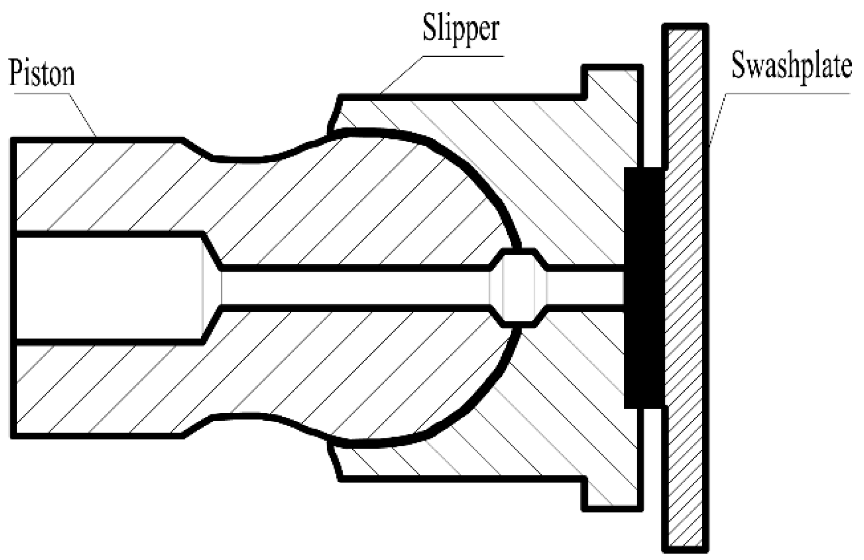
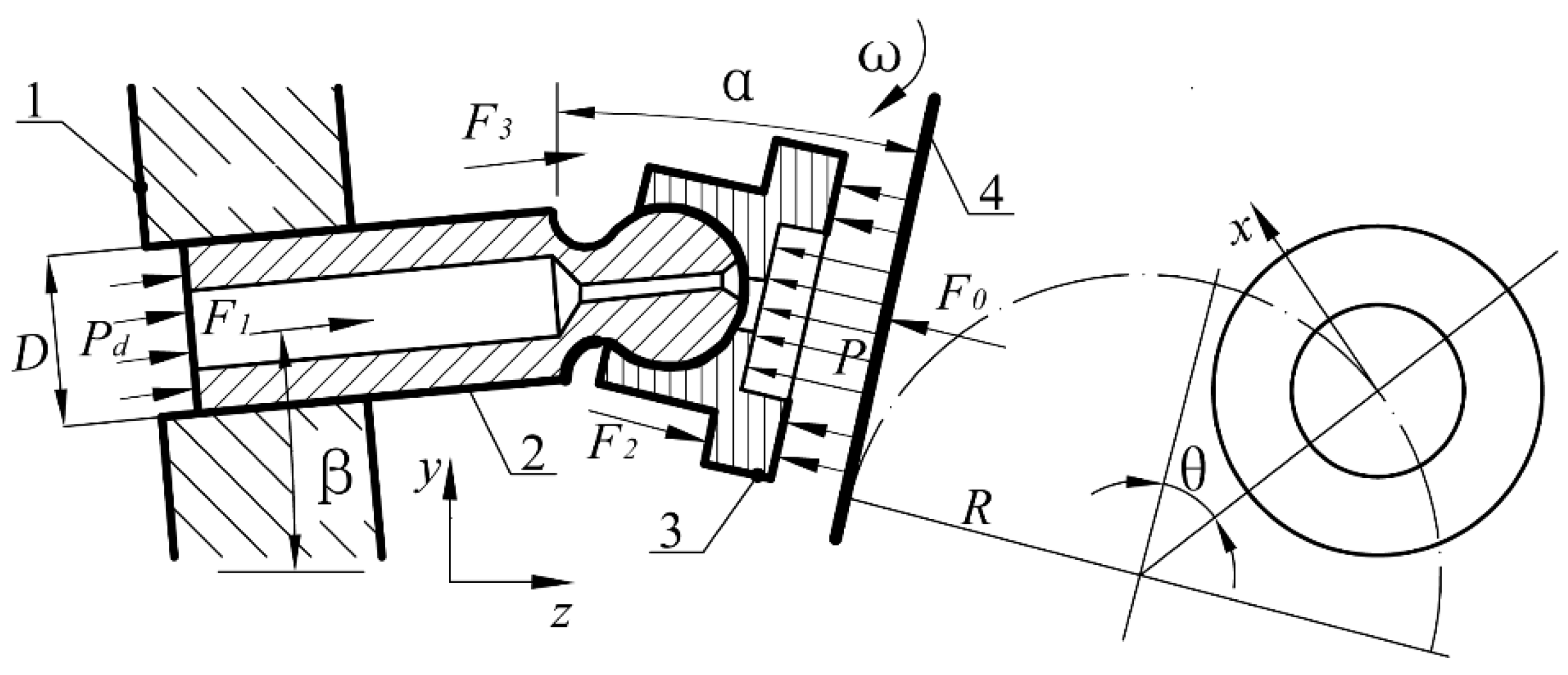
2.1. Modified Model of Oil Film Thickness

As shown in Figure 1, the piston slipper assembly studied in this paper is a single seal structure with hydrostatic support. The high-pressure oil enters the oil chamber at the bottom of the slipper through the piston cavity and the damping hole of the piston slipper assembly. Meanwhile, the oil film is formed between the slipper and the swashplate.
Hooke et al. [9] studied the hydro-dynamic parameter G , and the results show that the hydro-dynamic parameter G is a fixed value that does not change with the working conditions as the oil temperature and the structural form of the slipper pair are fixed. Ma et al. [33] verified the correctness of the above conclusions by the simulation using the software COMSOL. The hydro-dynamic parameter G proposed by Hooke is described as Equation (1), and it can be seen that the analysis of the oil film thickness according to the hydro-dynamic parameter G is feasible;
G = μ ν R 2 P h 2
where μ is the dynamic viscosity of oil, P is the pressure of the oil chamber, h is the oil film thickness of the slipper pair, R 2 is the outer radius of the slipper sealing ring, and ν is the rotation speed of the pump.
According to Equation (1), the theoretical oil film thickness at temperature T can be expressed as Equation (2);
h T = μ T ν R 2 P G T
where h T is the theoretical oil film thickness at temperature T, μ T is the dynamic viscosity of the oil at temperature T, and G T is the hydro-dynamic parameter at temperature T.
According to relevant research [34], the theoretical flow rate of the clearance between the slipper and the swash plate with the hydrostatic support structure can be expressed as Equation (3).
Q = π h 3 ( P P 0 ) 6 μ I n R 2 R 1
where P 0 is the oil pressure of the pump housing, and R 1 is the inner radius of slipper sealing ring.
Based on Equations (1)–(3), the theoretical flow rate of the slipper pair clearance at temperature T can be obtained as Equation (4);
Q T = π h T 3 ( P P 0 ) 6 μ T I n R 2 R 1
Due to the deviation between the actual flow rate and the theoretical flow rate, the oil film thickness can be corrected by the actual flow rate. Assuming that the actual flow rate of the slipper pair clearance is Q T when the temperature is T, the deviation ratio k between the actual flow rate Q T , and the theoretical flow rate Q T according to Equation (4) can be described as Equation (5);
k = Q T Q T Q T = ( h T h T ) 3 1
where h T is the modified oil film thickness, and h T can be described as Equation (6),
h T = ( k + 1 ) 1 / 3 · h T
According to Equation (2), h T can be transferred as Equation (7).
h T = ( k + 1 ) 1 / 3 · μ T ν R 2 P G T
The above model can be used to modify the theoretical oil film thickness of the slipper pair after verifying its correctness, which can provide a new method for the calculation of the oil film thickness and improve calculation accuracy further.

2.2. Calculation Model of Equivalent Friction Coefficient

The variation of the friction force of the slipper pair is complicated during the actual operation of a piston pump. In this paper, the calculation and the variation analysis of the equivalent friction coefficient are conducted based on the analysis of the friction force.
As illustrated in Figure 2, the force acting on the slipper mainly includes the force F 1 acting on the bottom of the piston, the pressing force F 2 of the spring, the axial inertia force F 3 generated by the piston slipper assembly, and the supporting force F 0 generated by the incomplete hydrostatic support on the bottom of the slipper.
The force F 1 acting on the bottom of the piston can be described as Equation (8),
F 1 = π D 2 4 p d
The pressing force F 2 of the spring can be described as Equation (9),
F 2 = F z Z
where F z is the pre-pressing force of the center springs in the pump, Z is the number of pistons.
The axial inertia force F 3 can be described as Equation (10),
F 3 = G g g R ω 2 t a n   α   c o s   θ
where G g is the total gravity of the piston and slipper, g is the acceleration of gravity.
The supporting force F 0 can be described as Equation (11),
F 0 = π ( R 2 2 R 1 2 ) 2 l n ( R 2 R 1 ) p d
According to Equations (8)–(11), the total pressure F perpendicular to the bottom of the slipper can be obtained as Equation (12),
F = F 1 c o s ( α + β ) + F 2 c o s   α + F 3 c o s ( α + β ) F 0
In most working conditions, the friction pair in the piston pump is in a mixed lubrication state [35,36]. It is difficult to distinguish dry friction, viscous friction, boundary friction, and other states separately and completely. In this paper, μ is used as the equivalent friction coefficient of the slipper pair during operation, that is, the friction coefficient under the interaction of the above states. According to Equation (12), the friction force F f of the slipper pair can be obtained as Equation (13),
F f = μ ( F 1 c o s ( α + β ) + F 2 c o s   α + F 3 c o s ( α + β ) F 0 )
Based on the friction model, the analysis of friction force and the equivalent friction coefficient of the slipper pair can be carried out. Furthermore, combined with the oil film thickness model, the relationship between the oil film thickness and the friction force can be further analyzed, providing theoretical support for the exploration of the friction characteristics of the slipper pair.

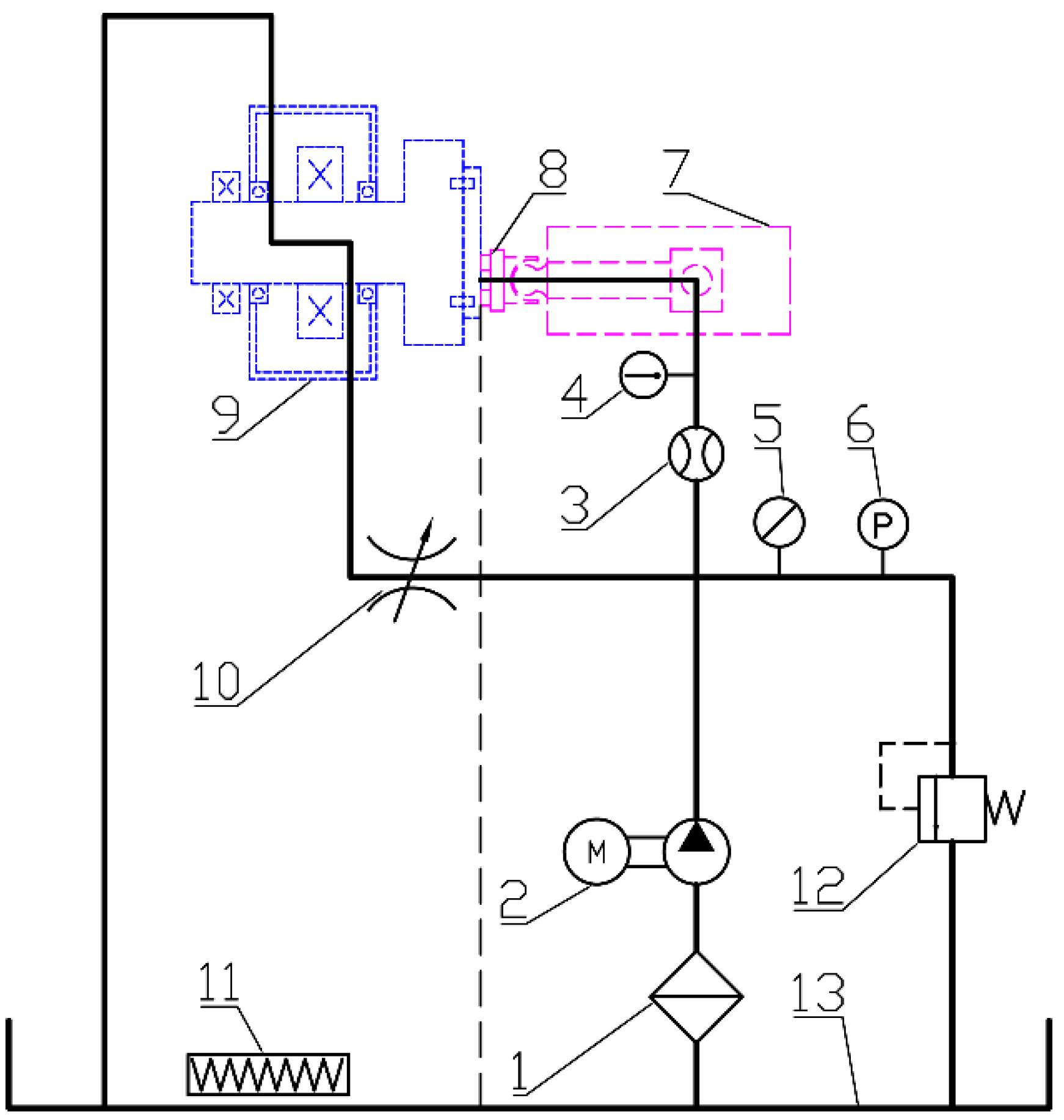
3. Testing Apparatus

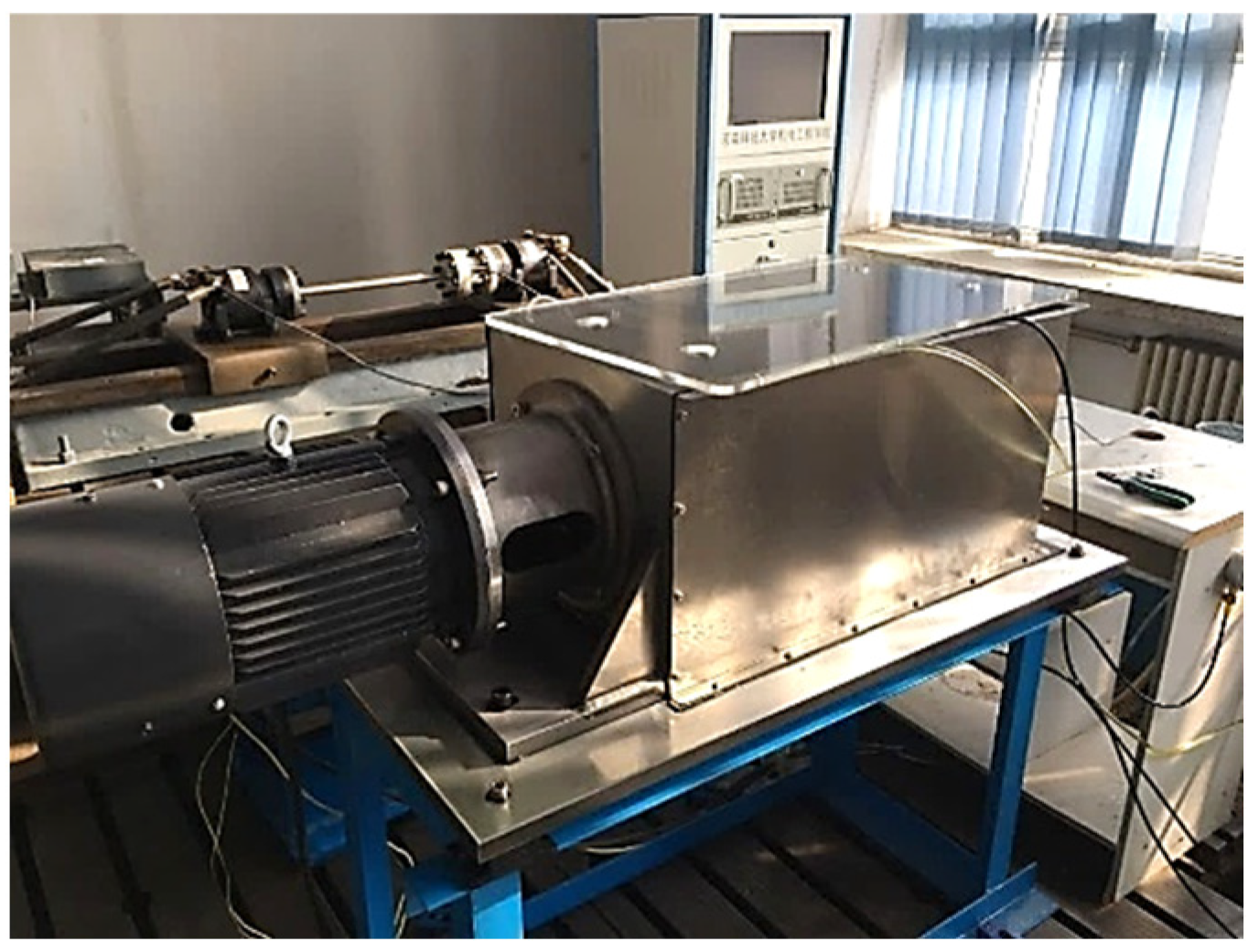
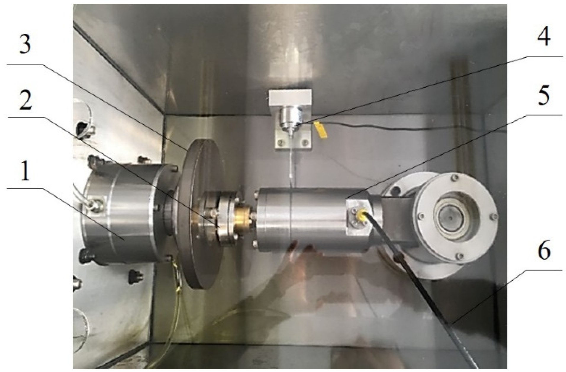
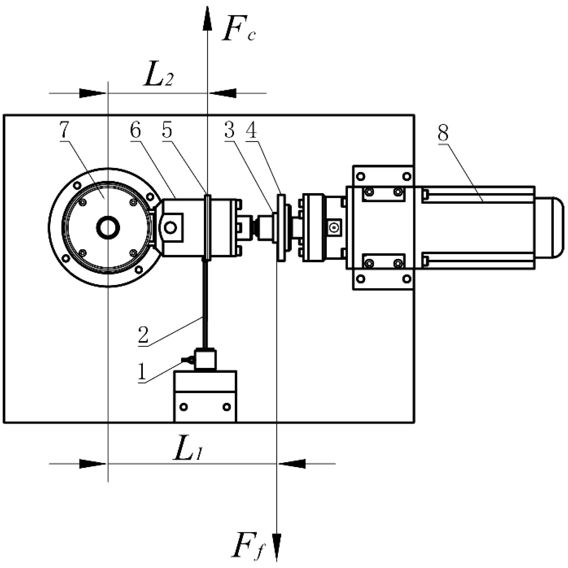
3.1. Test Bench Structure

To explore the friction characteristics of the slipper pair of high-pressure piston pumps with 750 mL/r displacement, the friction test bench of the slipper pair is designed according to the displacement ratio of 1:1. Different from the actual pump, the swashplate of this test bench is rotated and the piston slipper assembly is relatively fixed, by which can simulate the relative motion between slipper and swashplate. Figure 3 and Figure 4 show the overall structure of the test bench.
Figure 5 illustrates the principle of the hydraulic system of the test bench to simulate the actual operating pressure. To be specific, the gear pump is used as the power source to provide hydraulic oil for the piston cavity and the spindle bearing. A flowmeter is arranged in the oil branch of the piston cavity to monitor the oil flow between the slipper and the swashplate. The electric-eddy-type micro displacement sensor is embedded at the bottom of the slipper to measure the oil film thickness [19]. Set the temperature regulating device to ensure that the oil temperature is constant. The tension sensor, pressure sensor, temperature sensor, and data acquisition instrument are configured to collect the friction force, oil pressure, and oil temperature of the slipper pair in real-time separately. In addition, to ensure the lubrication cooling and the safety of the hydraulic oil circuit when the spindle rotates at high speed, the bearing lubrication branch and the safety device are set. In particular, before the measurement, it is also necessary to calibrate the zero position of each instrument and adjust the acquisition frequency of the acquisition instrument to ensure the data acquisition process is effective. At least two calibrated electric-eddy-type micro displacement sensors should be used for cross reference and verification, which can ensure the validity of data in the oil film thickness measurement process, and other precautions refer to ASTM G115-10 (2018). The parameters of the main measuring instruments are shown in Table 1.

3.2. Friction Test Principle

As shown in Figure 6, the friction force of the slipper pair is formed by the relative moving and positive pressure between the slipper and the swashplate by injecting high-pressure oil into the bottom of the piston cavity. During the relative motion of the slipper pair, the friction force of the slipper pair is transmitted to the tension sensor through the pull rod. Using the principle of moment balance, the friction force between the slipper pair can be obtained by calculation.
The torque balance between the friction force F f of the slipper pair and the pull force F c of the pull rod can be maintained when the slipper pair runs stably, and the equilibrium equation can be described as Equation (14),
L 1 F f = F c L 2
The friction force F f of the slipper pair can be obtained as Equation (15).
F f = F c L 2 L 1

4. Test Analysis

The oil film thickness and friction force of the slipper pair are mainly related to the working pressure, rotational speed, and oil temperature of the piston pump [37,38]. To explore the variation law of the oil film thickness and friction force of the slipper pair with the above parameters, verify the modified oil film thickness model, and determine the range of the equivalent friction coefficient under the 750 mL/r displacement condition, the test conditions are set as follows:
  • The oil temperature is set to a constant temperature of 40 °C (close to the temperature of long-term operation under actual working conditions).
  • The working pressure is set to 5, 10, 15, 20, 25, 30, 35 MPa.
  • The swashplate speed is set to 1000, 1400, 1800, 2200 r/min.
The clearance flow, oil film thickness, and friction force of the slipper pair are tested respectively under the above conditions. Then the modified oil film thickness and equivalent friction coefficient under the corresponding conditions can be calculated respectively using the models established, and the variation law can be analyzed.

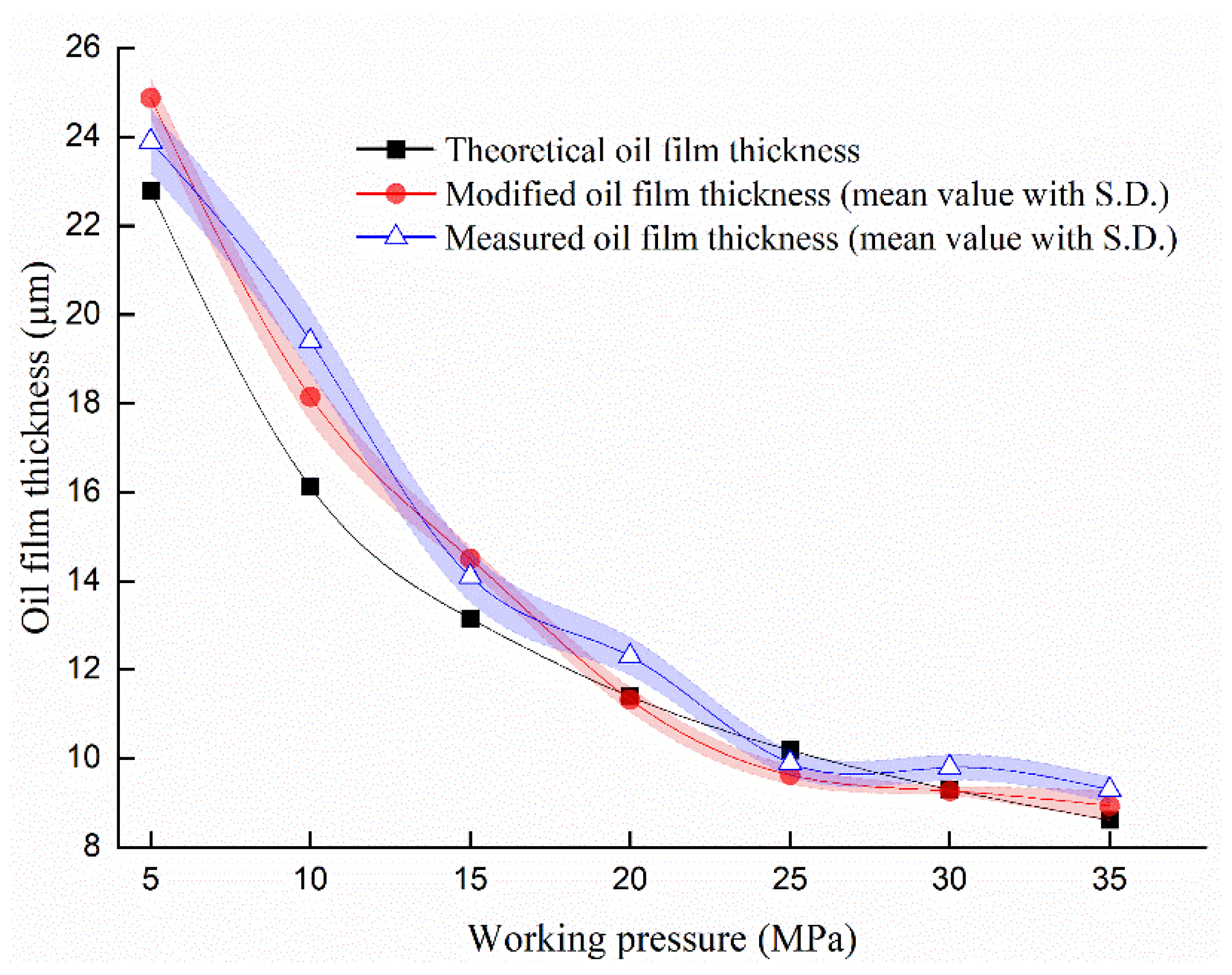
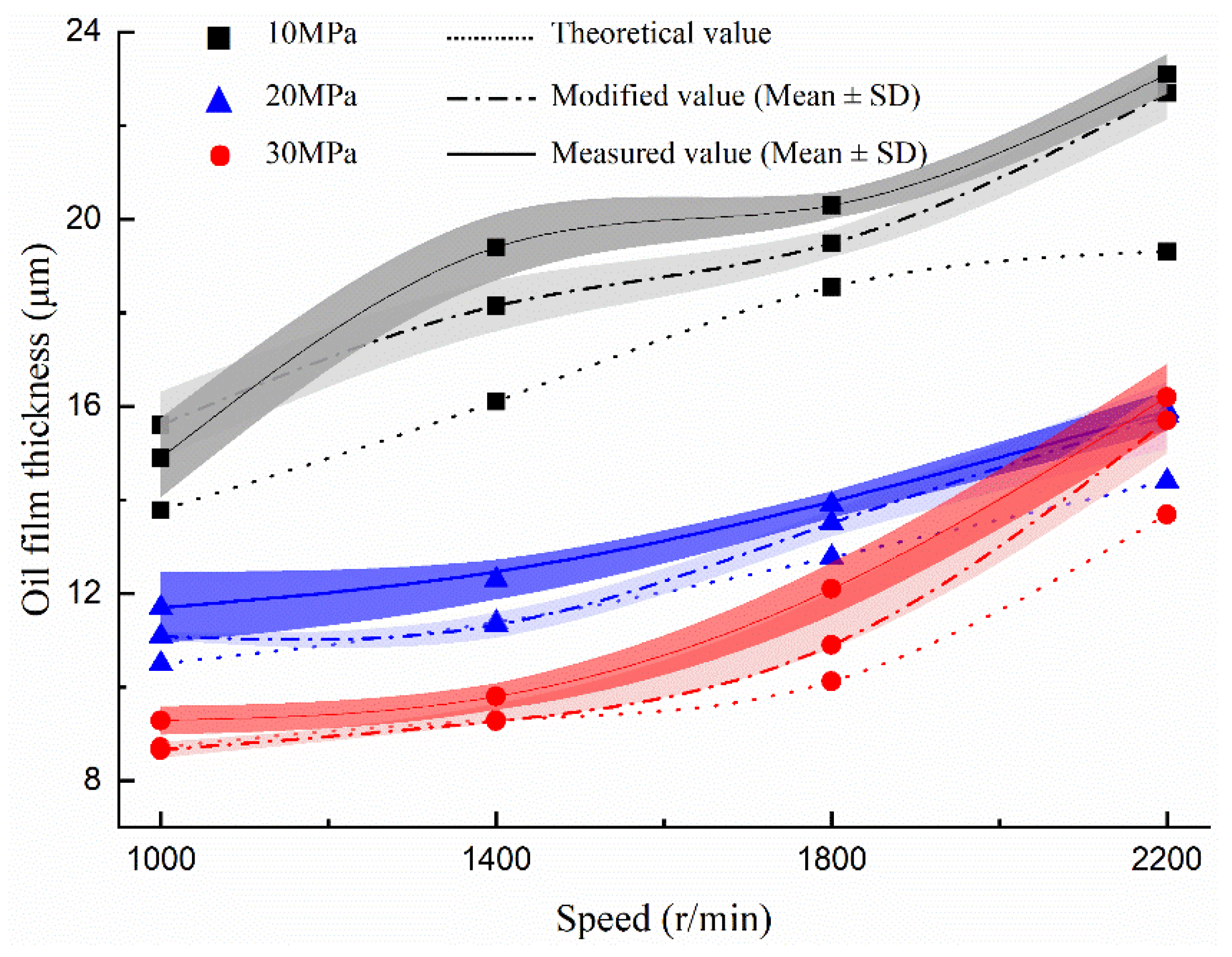
4.1. Oil Film Thickness Analysis

To simplify the analysis, take the condition at the speed of 1400 r/min as an example first, and explore the variation of the oil film thickness with the working pressure. Figure 7 depicts the variation curve of the slipper pair clearance flow with working pressure at 1400 r/min. It can be inferred that the higher the working pressure, the smaller the slipper pair clearance flow, which verifies the negative correlation between the slipper pair clearance flow and the working pressure. In the meantime, the deviation between the actual flow rate and the theoretical flow rate decreases with the increase of the working pressure, which can be found by the change of the flow deviation ratio k in Figure 7. Furthermore, the higher agreement between theoretical flow and actual flow with the higher working pressure, especially in the pressure range of 20–35 MPa, in which range the average flow deviation ratio k is about 5%, indicating that the theoretical calculation flow rate and the actual flow rate have good consistency under high-pressure conditions.
According to Equations (2) and (7) and the deviation ratio k in Figure 7, the theoretical value and the modified value of the oil film thickness of the slipper pair can be calculated, respectively, and the variation curve can be obtained, as illustrated in Figure 8. It can be seen that the higher the working pressure, the smaller the oil film thickness, and the trend is consistent with the variation of the clearance flow. Apart from that, the difference between the theoretical value and the modified value in the pressure range of 5~15 MPa is within 1–2 μm, and within 1 μm in the pressure range of 20~35 MPa, indicating that the difference between the theoretical value and the modified value becomes smaller in the high-pressure area, as the compression force of the slipper becomes larger. In addition, the measured value, as can be seen in Figure 8, is generally larger than both of the theoretical and modified values. More obviously, the modified value is more consistent with the measured value, with less deviation.
To further study the trend of the modified oil film thickness model under various working conditions, the theoretical and modified values of the oil film thickness under each speed with the working pressure 10, 20, and 30 MPa are calculated, respectively, and compared with the measured values, as shown in Figure 9. As can be seen in the figure, the oil film thickness increases with speed and decreases with pressure. In addition, the mean line of the modified method is closer to that of the measured one compared with the theoretical method, and the overlapping area between the modified value and the measured value is higher considering the standard deviation. More interestingly, it can be found that there is always a difference between the three methods. According to the analysis of the calculation model and relevant documents [18,39,40], the difference between the modified method and the theoretical one is mainly due to the difference in the leakage amount between theory and practice. Since the leakage amount affects the radial flow rate of the oil, and the radial flow rate is negatively correlated with the oil film thickness, when the leakage amount is different, the radial flow rate changes, and the oil film thickness is also different. Comparatively, the difference between the measured value and the calculated value (including modified value and theoretical value) may be that the factors considered in the calculation model are not enough to fully cover the ones affecting the actual operation of the pump, which needs further investigation.
To further quantify the difference between the two methods, the deviation ratio between the value of the theoretical and the measured, also the value of the modified and the measured, are calculated and compared respectively under the working pressure of 10–30 MPa and the speed of 1000–2200 r/min, as shown in Table 2.
In Table 2, the mean deviation ratio of the oil film thickness obtained by the modified method at different rotational speeds is mainly within 6%, while that of the theoretical method is mainly from 6% to 8%. Moreover, the difference between the two kinds of deviation ratio is mainly negative, representing that the mean deviation ratio by the modified method is lower than that of the theoretical method. Furthermore, the mean of the difference is about −3% (the specific value is −2.98%), indicating that the modified method is closer to the measured value in contrast with the theoretical one. However, considering the standard deviation, the benefit of the modified method will be weakened, suggesting that the applicability of this modified method under certain working conditions (such as under 2200 r/min, 1000 r/min with 25 MPa conditions) needs to be further verified. But overall, the modified method can improve the accuracy of the theoretical calculation to some extent, which can be used as a reference in the design process of the oil film thickness of 750 mL/r displacement piston pumps.

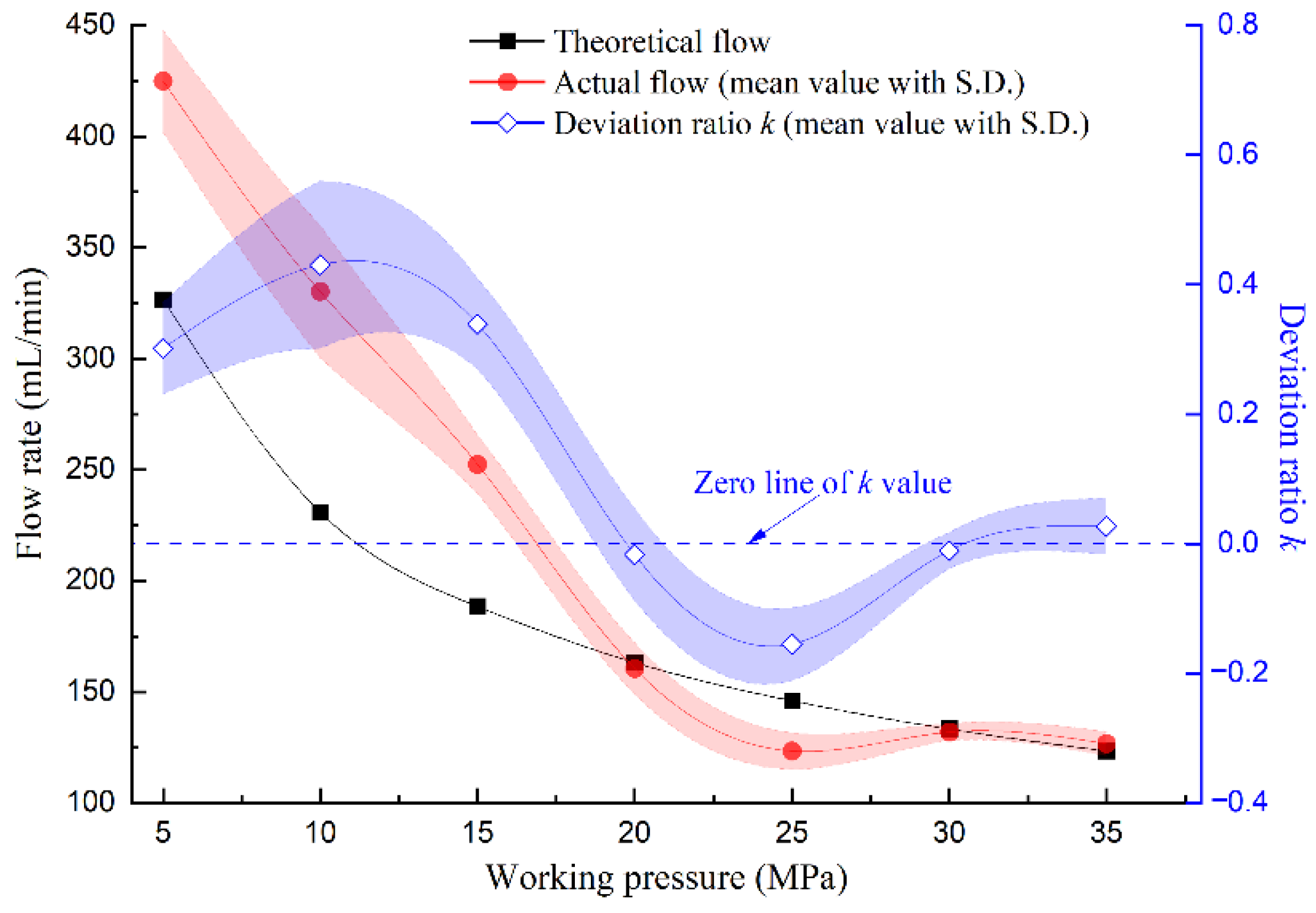
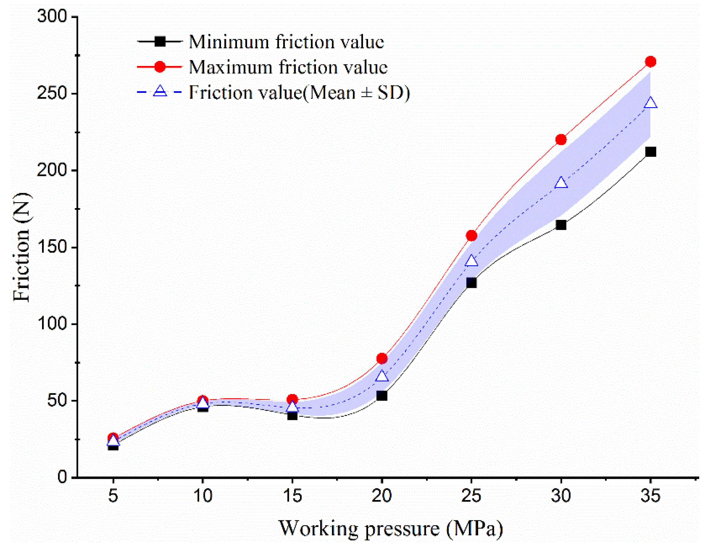
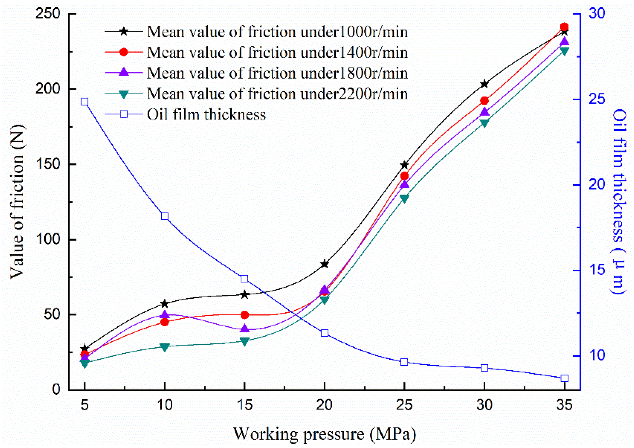
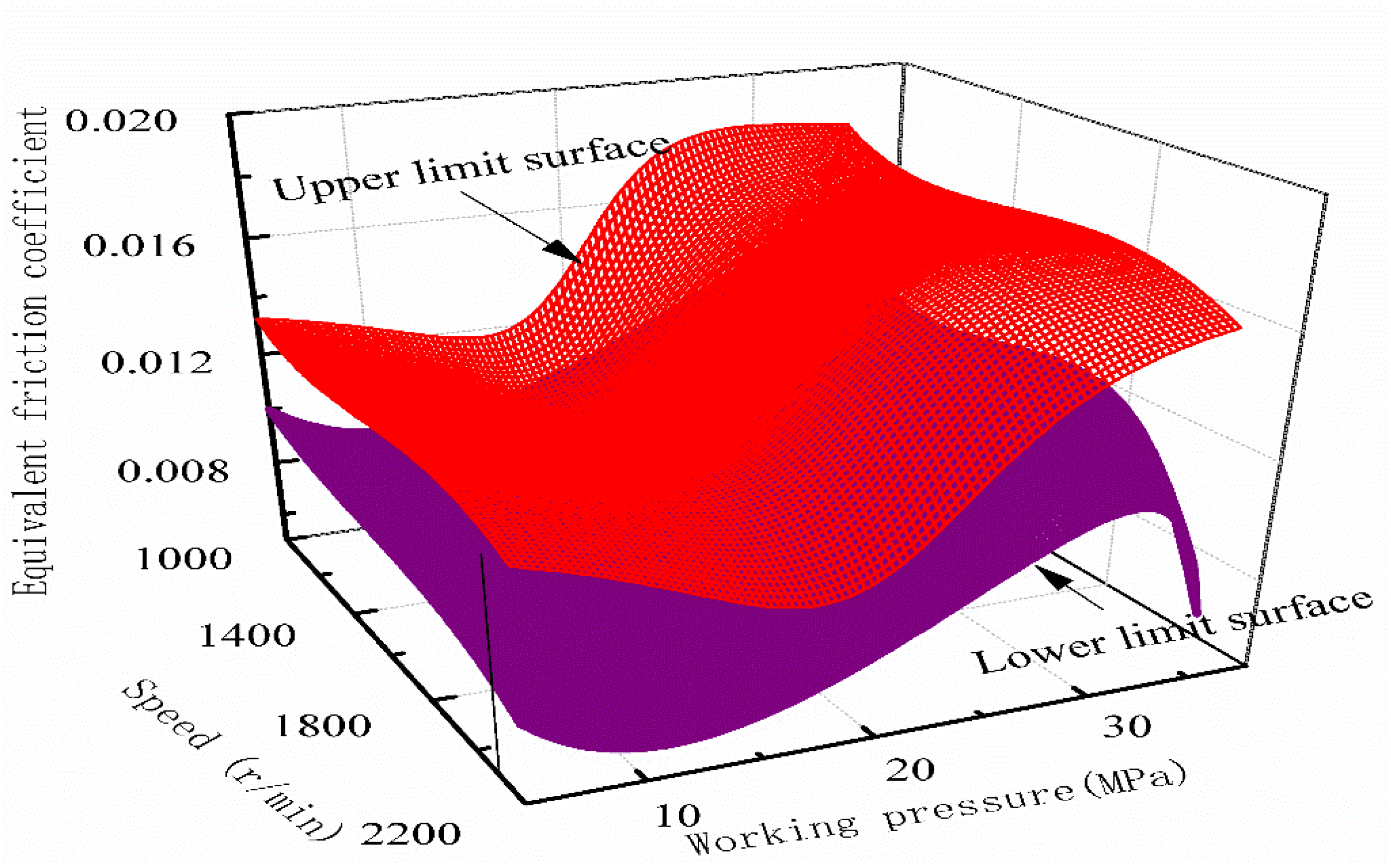
4.2. Equivalent Friction Coefficient Analysis

According to Equation (15), the friction force of the slipper pairs under different working pressures can be calculated, and the curve of the friction force varying with working pressures at the speed of 1400 r/min can be obtained, as demonstrated in Figure 10. It can be seen that the mean value of the friction generally increases with the increase of the working pressure. Similarly, the trend also applies to the fluctuation of the friction, especially when the pressure is above 20 MPa, showing that the fluctuation between the maximum and minimum values can reach 30~50 N. Additionally, compared with the oil film thickness curve in Figure 8, the variation trend of the friction value is opposite, which is mainly due to the increase of the shear stress on the bottom of the slipper when the oil film thickness is small and the external force on the slipper is large [34].
Based on the above friction data, the equivalent friction coefficient at 1400 r/min can be calculated by Equation (13), as shown in Figure 11. It can be observed that the equivalent friction coefficient increases with the increase of the friction on the whole, and decreases in the pressure range of 10–20 MPa and 25–30 MPa, indicating that the equivalent friction coefficient is volatile and fluctuates from 0.007 to 0.018.
Using the above method, calculate the mean value of the friction force and the equivalent friction coefficient at each speed respectively, and obtain the variation curve, as demonstrated in Figure 12 (corresponding standard deviation in Table 3) and 13. It can be seen from Figure 12 that the friction force decreases with the increase of the rotational speed and increases with the increase of the working pressure. More specifically, in the pressure range of 5–15 MPa, the influence of the working pressure on friction force is less than that of rotational speed, while in the pressure range of 15–35 MPa, the influence law is the opposite. Besides, comparing the oil film thickness curve, it can be observed that the friction value is negatively correlated with the oil film thickness during the variation of the working pressure, that is, the smaller the oil film thickness is, the greater the relative friction value is.
In Figure 13, the overall trend of the equivalent friction coefficient increases with the increase of working pressure. In terms of the influence of rotational speed, the equivalent friction coefficient decreases with the increase of rotational speed in the pressure range of 25–35 MPa, which is not obvious in other pressure ranges. According to the analysis of the oil film thickness, the equivalent friction coefficient increases with the decrease in oil film thickness basically.
After obtaining the curves of the equivalent friction coefficient at each speed and working pressure, the Gaussian function is used to fit the upper and lower limits of the equivalent friction coefficient under each working condition. The upper and lower limit surfaces with the variation of speed and working pressure are obtained, respectively, as shown in Figure 14.
The enclosed area between the upper and lower limit surfaces shown in Figure 14 is the variation range of the equivalent friction coefficient of the slipper pair under the test condition. The following rules can be found:
(1) The influence on the equivalent friction coefficient affected by the rotational speed is not significant relatively under the fixed working pressure. To be specific, the difference of the equivalent friction coefficient fluctuation range varying with the rotational speed is about 0.002~0.004, and the fluctuation is more significant in the 20–35 MPa pressure range compared with the 5–15 MPa pressure range, which is especially obvious under the high-speed and high-pressure conditions.
(2) The influence on the equivalent friction coefficient affected by the working pressure is highly significant under the fixed speed. To be specific, the difference of the equivalent friction coefficient fluctuation range varying with the working pressure is about 0.004~0.010, and the overall trend of the equivalent friction coefficient increases with the increase of working pressure.
It can be seen that the equivalent friction coefficient is greatly affected by the working pressure, which is mainly because the temperature, material, motion state, and other factors during the slipper pair’s motion are more sensitive to the pressure change, causing the friction coefficient to fluctuate significantly. Consequently, the working pressure can be given priority as the design basis of the equivalent friction coefficient.
On the whole, the equivalent friction coefficient of the slipper pair fluctuates in the range of 0.006–0.018 under the test conditions and varies in different pressure ranges. Specifically, in the pressure range of 15–20 MPa, the value is relatively stable and small, which varies between 0.008 and 0.012, considering that this pressure range can be used as the long-term operating pressure of the slipper pair. In the pressure range of 20–30 MPa, the equivalent friction coefficient increases significantly, considering that the pressure range can be used as the instantaneous high-pressure condition of the slipper pair, but it is not suitable for long time operation because of the friction and wears. In the pressure range of 30–35 MPa and the speed range of 2000–2200 r/min, the lower limit surface of the equivalent friction coefficient decreases rapidly, and the difference between the upper and lower limits increases sharply. Considering drastic fluctuations, to ensure the safe and reliable operation of the slipper pair, it is better to avoid the operation or shorten the working hours in this range.

5. Conclusions

To explore the friction characteristics of the slipper pair suitable for large displacement high-pressure piston pumps, a friction test bench for the slipper pair with 750 mL/r displacement was designed, and relevant tests were carried out. Besides, the existing theoretical oil film thickness was modified by the actual clearance flow of the slipper pair, and then the modified model was verified by the deviation ratio with the actual oil film thickness. Finally, the friction force and equivalent friction coefficient of the slipper pair were analyzed with the modified oil film thickness. On the basis of the aforementioned results and discussion, the following conclusions can be drawn:
(1)
The mean deviation ratio between the modified oil film thickness value and the measured value is mainly within 6%, while that of the theoretical method is mainly from 6% to 8%, and the mean of the difference between the two deviation ratios is about 3%, indicating that it is feasible to improve the calculated value of oil film thickness to some extent by using the modified method. However, since the benefit of the modified method may be weakened considering the standard deviation, it is necessary to study the specific applicable conditions of this modified method further.
(2)
The equivalent friction coefficient of the slipper pair fluctuates in the range of 0.006~0.018 and is affected more significantly by the working pressure with a difference of 0.004~0.010 between the fluctuation values than that of rotational speed with a difference of 0.002~0.004, suggesting that the working pressure can be given priority as the design basis of the friction coefficient for the pump.
(3)
The modified method established in this paper can be used to correct the theoretical oil film thickness of the slipper pair as a reference for the 750 mL/r displacement piston pump design by using the deviation ratio k under corresponding working conditions. Correspondingly, the upper and lower limits of the fitting surface of the equivalent friction coefficient can provide a more accurate design boundary for the friction coefficient of the slipper pair of the pump, and the designer can select the friction coefficient value between the upper and lower reference according to the working conditions during the development of 750 mL/r displacement piston pumps.

Author Contributions

Conceptualization, Z.L.; Methodology, Y.B.; Software, L.Z.; Formal analysis, Z.L. and L.X.; Data curation, Z.R.; Writing—original draft, Z.L.; Writing—review & editing, G.G.; Project administration, S.X. All authors have read and agreed to the published version of the manuscript.

Funding

This research was funded by [the National Key Research and Development Program of China], grant number [2020YFB2007104]. And The APC was funded by [China Railway Engineering Equipment Group Co., Ltd.].

Acknowledgments

The authors would like to thank the support of the National Key Research and Development Program of China (Grant No. 2020YFB2007104).

Conflicts of Interest

The authors declare no conflict of interest.

References

  1. Bergada, J.M.; Kumar, S.; Davies, D.L.; Watton, J. A complete analysis of axial piston pump leakage and output flow ripples. Appl. Math. Model. 2011, 36, 1731–1751. [Google Scholar] [CrossRef]
  2. Xu, B.; Hu, M.; Zhang, J.-Z.; Mao, Z.-B. Distribution characteristics and impact on pump’s efficiency of hydro-mechanical losses of axial piston pump over wide operating ranges. J. Cent. South Univ. 2017, 24, 609–624. [Google Scholar] [CrossRef]
  3. D’Andrea, D.; Epasto, G.; Bonanno, A.; Guglielmino, E.; Benazzi, G. Failure analysis of anti-friction coating for cylinder blocks in axial piston pumps. Eng. Fail. Anal. 2019, 104, 126–138. [Google Scholar] [CrossRef]
  4. Deng, H.; Hu, C.; Wang, Q.; Wang, L.; Wang, C. Friction and wear analysis of the external return spherical bearing pair of axial piston pump/motor. Mech. Ind. 2020, 21, 104. [Google Scholar] [CrossRef] [Green Version]
  5. Shen, H.; Zhou, Z.; Guan, D.; Liu, Z.; Jing, L.; Zhang, C. Dynamic Contact Analysis of the Piston and Slipper Pair in Axial Piston Pump. Coatings 2020, 10, 1217. [Google Scholar] [CrossRef]
  6. Li, S. Analysis of Instantaneous Flow and Slipper Pair Dynamics of High Pressure and Large Displacement Radial Piston Pump. Ph.D. Thesis, Lanzhou University of Technology, Lanzhou, China, 2021. [Google Scholar]
  7. Li, S.; Yang, P.; Bao, S.; Li, Y. Numerical simulation of fluid-structure-thermal coupling of slipper pair in high-pressure and large-displacement radial piston pump. J. Drain. Irrig. Mach. Eng. 2022, 40, 887–894. [Google Scholar]
  8. Hooke, C.J.; Kakoullis, Y.P. The effects of non-flatness on the performance of slipper in axial piston pumps. Proc. Inst. Mech. Eng. Part C J. Mech. Eng. Sci. 1988, 197, 239–247. [Google Scholar] [CrossRef]
  9. Hooke, C.J.; Li, K.Y. The lubrication of slippers in axial piston pumps and motors-the effect of tilting couples. Proc. Inst. Mech. Eng. Part C J. Mech. Eng. Sci. 1989, 203, 343–350. [Google Scholar] [CrossRef]
  10. Koc, E.; Hooke, C.; Li, K. Slipper balance in axial piston pumps and motors. J. Tribol. 1992, 114, 766–772. [Google Scholar] [CrossRef]
  11. Koc, E.; Hooke, C. Investigation into the effects of orifice size, offset and overclamp ratio on the lubrication of slipper bearings. Tribol. Int. 1996, 29, 299–305. [Google Scholar] [CrossRef]
  12. Harris, R.; Edge, K.; Tilley, D. Predicting the behavior of slipper pads in swashplate-type axial piston pump. J. Dyn. Sys. Meas. Control. 1996, 118, 41–47. [Google Scholar] [CrossRef]
  13. Zhao, K.; He, T.; Wang, C.; Chen, Q.; Li, Z. Lubrication characteristics analysis of slipper pair of digital valve distribution axial piston pump. Adv. Mech. Eng. 2022, 14, 16878132221085442. [Google Scholar] [CrossRef]
  14. Sun, Y.; Jiang, J.; Liu, C. Oil film characteristics and power consumption of slipper pair under redundant pressing force. J. South China Univ. Technol. (Nat. Sci.) 2011, 39, 6. [Google Scholar]
  15. Shen, R.; Pan, Y. Friction characteristic analysis of slipper pair in A11VO190 axial piston pumps. Chin. J. Eng. Des. 2014, 21, 51–55. [Google Scholar]
  16. He, B.; Sun, J.; Ye, Z. Calculation and analysis of film thickness for slipper pair and valve plate pair in fuel piston pump. J. Aerosp. Power 2010, 25, 1437–1442. [Google Scholar]
  17. Liu, H.; Yuan, S.; Peng, Z. Dynamic Simulation of Slipper Bearings in Axial Piston Pumps. Trans. Beijing Inst. Technol. 2011, 11, 1282–1286. [Google Scholar]
  18. Tang, H.; Yin, Y.; Li, J. Characteristics of clearance leakage and friction torque of slipper pair in axial piston pump. J. South China Univ. Technol. (Nat. Sci.) 2014, 42, 74–79. [Google Scholar]
  19. Lin, S.; Hu, J. Tribo-dynamic model of slipper bearings. Appl. Math. Model. 2015, 39, 548–558. [Google Scholar] [CrossRef]
  20. Kazama, T. Mixed Lubrication Characteristics of Dynamically Loaded Hydrostatic Spherical Bearings (Numerical Simulation at Operating Conditions of Piston Pumps/Motors). Trans. Jpn. Soc. Mech. Eng. Ser. C 2003, 69, 2200–2205. [Google Scholar] [CrossRef] [Green Version]
  21. Ernst, M.; Ivantysynova, M. Axial Piston Machine Cylinder Block Bore Surface Profile for High-Pressure Operating Conditions with Water as Working Fluid. In Proceedings of the 2018 Global Fluid Power Society PHD Symposium (GFPS), Samara, Russia, 18–20 July 2018; pp. 1–7. [Google Scholar]
  22. Pelosi, M.; Ivantysynova, M. A geometric multigrid solver for the piston-cylinder interface of axial piston machines. Tribol. Trans. 2012, 55, 163–174. [Google Scholar] [CrossRef]
  23. Tang, H.; Ren, Y.; Xiang, J. A Novel Model for Predicting Thermoelastohydrodynamic Lubrication Characteristics of Slipper Pair in Axial Piston Pump. Int. J. Mech. Sci. 2017, 124–125, 109–121. [Google Scholar] [CrossRef]
  24. Wang, Z.; Han, B.; Sun, L. Analysis of Elastohydrodynamic Lubrication (EHL) Characteristics of Port Plate Pair of a Piston Pump. Machines 2022, 10, 1109. [Google Scholar] [CrossRef]
  25. Hu, J.; Zhao, H.; Jing, C. Hydrodynamic lubrication characteristics of slipper/swash plate pair in axial piston pumps-theory and experiment. Trans. Beijing Inst. Technol. 2018, 38, 229–234. [Google Scholar]
  26. Xu, L.; Lu, Y.; Liu, Q.; Lin, L.; Mu, J. Experimental Study on Frictional Pairs of Piston Pumps. J. Fail. Anal. and Prev. 2022, 22, 738–749. [Google Scholar] [CrossRef]
  27. Li, X. Research on the Effect of Varying Load on the Characteristics of Oil Film for Slipper Pair of Radial Piston Pumps. Master’s Thesis, Lanzhou University of Technology, Lanzhou, China, 2018. [Google Scholar]
  28. Tang, H.S.; Yin, Y.B.; Ren, Y.; Xiang, J.; Chen, J. Impact of the thermal effect on the load-carrying capacity of a slipper pair for an aviation axial-piston pump. Chin. J. Aeronaut. 2018, 31, 195–209. [Google Scholar] [CrossRef]
  29. Xu, B.; Li, Y.; Zhang, B.; Zhang, J. Numerical simulation of overturning phenomenon of axial piston pump slipper pair. J. Mech. Eng. 2010, 46, 161–168. [Google Scholar] [CrossRef]
  30. Ma, J.; Wang, Z.; Wang, K. Analysis Method of Slipper /Swash Plate Pair Film Characters Considering Bearing Force of Rough Surface. Chin. Hydraul. Pneum. 2022, 46, 101–108. [Google Scholar]
  31. Tang, H.; Ren, Y.; Xiang, J.; Anil, K. Evaluation and optimization of axial piston pump textured slipper bearings with spherical dimples based on hybrid genetic algorithm. Proc. Inst. Mech. Eng. Part J J. Eng. Tribol. 2021, 235, 1719–1741. [Google Scholar] [CrossRef]
  32. Chen, F.; Wu, X.; Cha, P.; Yin, F. Numerical Simulation of Dynamic Characteristics of Slipper Pair Oil Film of Piston Pump. Mach. Tool Hydraul. 2022, 50, 127–134. [Google Scholar]
  33. Ma, J.; Li, Q.; Ren, C.; Chen, J. Influence factors analysis on wear of hydraulic axial piston pump/slipper pair. J. Beijing Univ. Aeronaut. Astronaut. 2015, 41, 405–410. (In Chinese) [Google Scholar] [CrossRef]
  34. Zhang, X. Research on the Oil Film Characteristics of Slipper Pair and Piston Pair in Aviation Axial-Piston Pump. Master’s Thesis, Zhejiang University, Hangzhou, China, 2016. [Google Scholar]
  35. Fisher, M.J. A Theoretical Determination of Some Characteristics of a Tilted Hydrostatic Slipper Bearing; British Hydromechanics Research Association: Bedfordshire, UK, 1962. [Google Scholar]
  36. Hashemi, S.; Kroker, A.; Bobach, L.; Bartel, D. Multibody dynamics of pivot slipper pad thrust bearing in axial piston machines incorporating thermal elastohydrodynamics and mixed lubrication model. Tribol. Int. 2016, 96, 57–76. [Google Scholar] [CrossRef]
  37. Pang, Z.; Zhai, W.J.; Shun, J.W. The Study of Hydrostatic Lubrication of the Slipper in a High-pressure Plunger Pump. Tribol. Trans. 1993, 36, 316–320. [Google Scholar] [CrossRef]
  38. Manring, N.D.; Wray, C.L.; Dong, Z. Experimental Studies on the Performance of Slipper Bearings within Axial-Piston Pumps. J. Tribol. 2004, 126, 511–522. [Google Scholar] [CrossRef]
  39. Tang, H.; Li, J.; Yin, Y. Power loss characteristics of slipper/swash plate pair in axial piston pump. J. Cent. South Univ. (Sci. Technol.) 2017, 48, 361–370. [Google Scholar]
  40. Bergada, J.M.; Haynes, J.M.; Watton, J. Leakage and groove pressure of an axial piston pump slipper with multiple lands. Tribol. Trans. 2008, 51, 469–482. [Google Scholar] [CrossRef]
Figure 1. The structure diagram of the piston slipper assembly.
Lubricants 10 00363 g001
Figure 2. The force analysis diagram of the piston slipper assembly (1, cylinder; 2, piston; 3, slipper; 4, swashplate; D , piston diameter; P d , piston cavity pressure; ω , slipper angular velocity; R , piston distribution circle radius; α , swashplate angle; β , piston dip angle; and θ , slipper rotation angle).
Lubricants 10 00363 g002
Figure 3. The external structure of the test bench.
Lubricants 10 00363 g003
Figure 4. The internal structure of the test bench (1, mainshaft; 2, slipper assembly; 3, swashplate; 4, tension sensor; 5, piston assembly; 6, pressure oil circuit).
Lubricants 10 00363 g004
Figure 5. Hydraulic system diagram of the test bench (1, filter; 2, gear pump; 3, flowmeter; 4, temperature sensor; 5, pressure gauge; 6, pressure sensor; 7, piston slipper assembly; 8, electric-eddy-type micro displacement sensor; 9, swashplate assembly; 10, throttle valve; 11, temperature regulator; 12, safety valve; 13, oil tank).
Lubricants 10 00363 g005
Figure 6. Test principle of the slipper pair friction (1, tension sensor; 2, pull rod; 3, slipper assembly; 4, swashplate assembly; 5, pull rod ring; 6, piston assembly; 7, simulation component of flow distribution pair; 8, motor).
Lubricants 10 00363 g006
Figure 7. Variation of the clearance flow under various working pressures (1400 r/min).
Lubricants 10 00363 g007
Figure 8. Variation of the oil film thickness under various working pressures (1400 r/min).
Lubricants 10 00363 g008
Figure 9. Variation of oil film thickness versus speed under different working pressures.
Lubricants 10 00363 g009
Figure 10. Variation of the friction under various working pressures (1400 r/min).
Lubricants 10 00363 g010
Figure 11. Variation of the equivalent friction coefficient under various working pressure (1400 r/min).
Lubricants 10 00363 g011
Figure 12. Variation of the friction versus working pressures under different speeds.
Lubricants 10 00363 g012
Figure 13. Variation of the equivalent friction coefficient versus working pressures under different speeds.
Lubricants 10 00363 g013
Figure 14. Fitting surfaces of the equivalent friction coefficient under various working pressure and speed.
Lubricants 10 00363 g014
Table 1. Parameters of the measuring instruments.
Measuring InstrumentsTechnical Parameters
Measurement RangeAccuracy
Flowmeter0–1000 mL/min±0.01%
Temperature sensor0–100 °C±0.05 °C
Pressure sensor0–50 MPa±0.1%
Electric-eddy-type micro displacement sensor0–200 μm±0.005%
Tension sensor0–500 N±0.02%
Table 2. Comparison between the two kinds of deviation ratios.
Speed
(r/min)
Working Pressure (MPa)Deviation Ratio of Theoretical Method (A)Deviation Ratio of Modified MethodDifference between the Two Methods (C)Mean of the Difference C
Mean (B)SDB-AMean ± SD
1000107.52%4.69%0.26%−2.83%−2.98% ± 1.95%
156.81%5.94%0.68%−0.87%
2010.05%5.98%0.38%−4.07%
256.01%6.93%0.52%0.92%
304.56%4.52%0.36%−0.04%
14001014.08%9.64%0.69%−4.44%
156.71%4.66%0.32%−2.05%
207.41%7.95%0.33%0.54%
257.15%4.47%0.53%−2.68%
305.16%2.01%0.25%−3.15%
1800108.02%4.51%0.42%−3.51%
156.07%6.84%0.39%0.77%
208.05%3.94%0.37%−4.11%
256.79%4.01%0.46%−2.78%
3015.26%8.62%0.41%−6.64%
22001014.40%6.04%0.38%−8.36%
157.15%4.97%0.49%−2.18%
209.43%3.13%0.40%−6.30%
256.05%7.10%0.58%1.05%
3014.97%6.10%0.21%−8.87%
Table 3. The mean with a standard deviation of friction under different speeds and working pressures.
Mean ± SDSpeed (r/min)
1000140018002200
Working pressure (MPa)527.42 ± 2.9723.46 ± 1.6920.85 ± 1.9817.96 ± 1.39
1057.36 ± 3.7445.12 ± 1.4149.70 ± 2.7428.84 ± 1.80
1563.49 ± 2.0149.87 ± 3.7240.39 ± 2.0732.72 ± 2.28
2083.73 ± 1.2765.45 ± 6.8766.43 ± 1.8460.38 ± 2.19
25149.52 ± 2.83142.30 ± 12.21136.35 ± 1.33127.66 ± 2.03
30203.55 ± 1.78192.37 ± 2.79184.65 ± 4.27177.95 ± 1.92
35238.52 ± 3.57241.50 ± 4.29231.31 ± 3.31225.90 ± 1.82
Publisher’s Note: MDPI stays neutral with regard to jurisdictional claims in published maps and institutional affiliations.

