Article

A Comparative Machinability Study of SS 304 in Turning under Dry, New Micro-Jet, and Flood Cooling Lubrication Conditions

1
Mechanical and Industrial Engineering Department, College of Engineering, Imam Mohammad Ibn Saud Islamic University (IMSIU), Riyadh 11432, Saudi Arabia
2
Department of Mechanical Engineering, C V Raman Global University, Bhubaneswar 752054, India
*
Author to whom correspondence should be addressed.
Lubricants 2022, 10(12), 359; https://doi.org/10.3390/lubricants10120359
Submission received: 11 November 2022 / Revised: 6 December 2022 / Accepted: 8 December 2022 / Published: 12 December 2022
(This article belongs to the Special Issue Methods of Application of Cutting Fluids in Machining)

Abstract

:
The main objective of this experimental investigation is to examine favourable machining conditions by utilising fewer resources of machining industries for the techno-economical and ecological benefits. The machining operations are performed in turning SS 304 using coated carbide tool inserts under dry, water-soluble cutting fluid solution in the form of flood cooling and small-quantity lubrication (SQL) conditions by employing a newly formed micro-jet for a comparative classical chips study and analysis. The machining experiments are conducted in turning by a 25 kW precision CNC lathe with a special arrangement of micro-jets into the machining zone. Machining speeds and feed rates are varied under dry, micro-jet, and flood cooling conditions and their effects are studied on the type of chips and their morphology, chip reduction coefficient (ξ), and chip shear plane distance (d). The effect of machining environments on tool health conditions (such as BUEs, tool-edge chipping, and edge breaking) is examined for the inferences. In the range of low-speed machining (less than 600 m/min), metal cutting seems easier in flood cooling conditions, but it imposes more unfavourable effects (such as edge chipping and edge breaking) on the ceramic cutting tool’s health. On the other hand, the dry machining condition shows a favourable performance for a ceramic cutting tool. The optimum machining condition is found in the micro-jet SQL by the analysis of experimental data and observation results for the tool and work combination. The analysis of the results is carried out by the response surface methodology (RSM) and artificial neural network (ANN). The ANN model is found to be more accurate than RSM. The aspects of effective green machining are emphasised.

1. Introduction

In the last two decades, the intense use of metal-working lubricants has been subjected to severe regulatory scrutiny on health hazards. Thus, the Metalworking Fluid Standards Advisory Committee (MWFSAC), USA authorised (in 1997) the allowable exposure level for metalworking fluids to be reduced from 5.0 mg/m3 to 0.5 mg/m3 as per the petition of United Auto Workers for the Occupational Safety and Health Administration (OSHA). As a result, the amount of permitted cutting fluid is decreased, which transforms flood cooling into nearly dry machining or into minimum-quantity lubrication (MQL) or small-quantity lubrication (SQL), which atomises the lubricant primarily using air as the carrier to create a thin aerosol [1]. The harmful substances present in the metal-cutting fluid cause complex health issues such as skin diseases, and respiratory diseases such as lung cancer. According to the National Institute for Occupational Safety and Health (NIOSH), around one million workers in the manufacturing industries were experiencing these health problems [2].

1.1. Role of Lubricants in Machining

The machining speed ranges are considered as high-speed machining for 600 to 1800 m/min, very-high-speed machining for 1800 to 18,000 m/min, and ultrahigh-speed machining for 18,000 m/min [1]. The coolant has very little access to the tool–workpiece or tool–chip interfaces where seizure conditions are established during and above high-speed machining. It may be caused by the coolant film boiling at high cutting temperatures, which causes the coolant to evaporate and create a blanket that impedes cutting fluid flow. In this situation, a high-pressure coolant supply is recommended to eliminate such seizure conditions [2]. At and above high-speed machining conditions, the chip–tool interface (cutting zone) temperature may reach 1200 °C [3]. It may even attain the work material melting point temperature (1464 °C in machining AerMet100 steel) [4] and raise situations such as hot machining [5]. To retain the mechanical and metallurgical properties in such high temperatures, advanced cutting tool materials (such as coated carbides, high-performance ceramics, cBN, and diamond as PCD and coating) are recommended [5]. The special-purpose (powerful, robust, and precision) machine tools are required to conduct high-speed machining and are approximately 50 times or higher costlier than the general-purpose machine tools, and some advanced cutting tools are not stable at higher temperatures (for example, cBN tools are stable up to 1200 °C, and TiAlN coating is stable up to 900 °C) [1]. The machining temperature above 650 °C causes high tool wear, poor surface finish, and a change in microstructure and hardiness [6]. To avoid such critical situations, low-speed machining (<600 m/min) is a normal practice in general machining industries and lubricants are commonly used for the ease of machining. The machining industry’s coolant cost involves about 16% of the typical end-user manufacturing costs shown in Figure 1 [7].
The MQL has become a sustainable [8] factor in the machining industry. A low-tribological-interface temperature is provided by the tribological film formed by homogenous mists in MQL-based fluids. The use of nanoparticles in MQL has been proven to increase the performance of lubricants where the nanoparticles serve as a spacer and decrease friction, rubbing, and ploughing at the tool–workpiece interface [9,10].

New Micro-Jet MQL

Hamran et al. 2020 [11] reviewed the state-of-the-art level status of SQL/MQL in the machining research domain and suggested the scopes for new SQL/MQL system design and development for effective applications in the machining industry. They discussed the state of research and future directions for the design of the SQL/MQL system, as illustrated in Figure 2 where the grave health concerns regarding nanosolid lubricants (NSLs) are alerted by the present authors.
The investigation scopes are well observed to develop applications of the new MQL system and nozzle, aiming for safe and effective application of MQL in machining. New micro-jet system designs and performance studies in green SQL/MQL supplies at the cutting zone in low pressure and high pressure may be investigated to reduce cooling costs.

1.2. Importance of Machining SS304

After steel, stainless steel (SS) is the second most prevalent material category in machine shops [12] and represents the highest annual (from 1980 to 2018) growth of production (5.40% per year) among engineering metals [13]. SS 304 is one of the most useful (58% in 2004) [14] alloys in all grades of SS, which has a machinability index of 43% [12], which indicates that the machining of SS 304 is near to the difficult-to-machine material zone. The demands of machining SS can be realised from its various applications, as referred to in Figure 3.
The present authors noticed that the machinability data of SS 304 are hardly available in open sources. Aslan et al. 2022 [8] mentioned that limited research is indeed published in the machining of structural steels. Usca et al. 2022 [15] investigated machinability matrices of AISI steel in milling under different cooling/lubrication conditions and observed the best machining performance in the cryo-LN2 cooling condition. The machinability study of SS 304 in this line of the present approach may be useful to the general-purpose machining industry.

1.3. The Advantages and Limitations of Dry, Flood Cooling, and MQL/SQL in Machining

Lubricants are effectively used in machining industries for low-speed machining. The comparative sustainability of such machining conditions is indicated in Table 1. To avail some benefits of lubrication effects in machining and to avoid the limitations of flood cooling to a large extent, MQL/SQL machining could be an optimum solution for the machining industries. The MQL/SQL provides several benefits including technological, economic, environmental, and operator health concerns [5].

1.4. Recent Status of Nanofluid MQL/SQL, Environment, and Health Issues

Sen et al. 2021 [16] extensively reviewed the aspects of eco-friendly cutting fluids of MQL. It is revealed that a significant number of experimental studies have already been reported worldwide in the area of nanofluid/nanoparticles (NPs) mixed with MQL applications in machining such as turning, drilling, milling, and grinding industries. The use of nano-Al2O3, nano-MoS2, nano-diamond, CNT, nano-SiO2, nano-ZrO2, graphene nanoplatelet, etc., in MQL is almost popular for its various advantages. The nanoparticles and their concentration with the type of MQL have shown a strong role in metal-cutting performance [21]. However, the toxicity of NPs and ionic MQL has not been well noticed before such industrial use. The NPs mixed in the mist can easily enter into the operator’s lungs where a rapid translocation through the bloodstream is possible to other vital organs. On the cellular level, the ability to act as a gene vector has been demonstrated for nanoparticles. Carbon black nanoparticles have been implicated in interfering with cell signalling [22]. The Edinburgh team concluded that ‘Our data suggest that nanoplatelets pose a novel nano-hazard and structure-toxicity relationship in nanoparticle toxicology’ [23]. Najahi-Missaoui et al. 2020 [24] extensively reviewed the exotic biomedical use of some NPs such as iron oxide, gold, and silver. They also mentioned the side-effects/toxic effects of some solid NPs: ‘solid NPs such as metal-containing or metal oxide NPs have been shown to cause oxidative stress, inflammation and DNA damage’. Plenty of research articles have already been reported on the toxicology of various NPs on biological and ecological concerns. Nouzil et al. 2022 [25] conducted an extensive review of the toxicity analysis of NPs in MQL and mentioned that ‘the current literature does not provide researchers in the machining sector with a comprehensive analysis of the toxicity of the nanoparticles used in nano-minimum quantity lubrication’.
Though most of the CNC lathes/machining centres in high-tech industries are operated in a closed enclosure, without confirming the health and biological safety issues, abandoned use of nanofluids in MQL may cause premature harm to manpower in future general machining industries. Some possible health issues related to nanoparticles are summarised in Table 2.
In this present work, the application of safe water-soluble cutting fluid is used in the form of new micro-jet MQL/SQL in machining (turning) stainless-steel 304 by using coated carbide cutting tools to beget economic benefit and environment-friendly machining. A wide range of cutting velocities and feed are maintained to collect machining chips for study and analysis. To compare and understand the effects of micro-jets, a similar set of experiments and investigations are conducted under dry and flood cooling conditions to attain the techno-economic viability and benefits of employing safe MQL/SQL in the form of micro-jets. The more economical machining process is always highly demanding and important for sustainability in the competitive world market. In this concern, a detailed machining chip study and analysis are performed to find out the machinability of highly useful SS 304. The experimental design, analysis, and validation method using ANOVA and ANN would be effective in making the work efforts concise and have precision in the decisions.

2. Materials and Methods

The machinability study in orthogonal turning is performed using the commercially available SS 304 rod (Ø × L: 20 mm × 50 mm) made by Girsh metal, India with the following composition, as given in Table 3 (manufacturer data sheet), and a density of 8.0 g/cm3, melting point of 1400 °C, TS: 75,000 PSI (515 MPa), YS: 3000 PSI (205 MPa), and 35% elongation capacity with a certified hydraulic test. The inset photograph of the SS 304 work material installed in the CNC lathe and the cutting ‘tool insert-tool holder’ details are given in Figure 4a,b, respectively.
The SANDVIK cormorant, India-made PVD (TiAlN + TiAiN)-coated carbide tool inserts (SNMG 12 04 08-MM 1115) and tool holder CoroTurn RC (DSBNR 2525M 12) are used in the machining experiments.
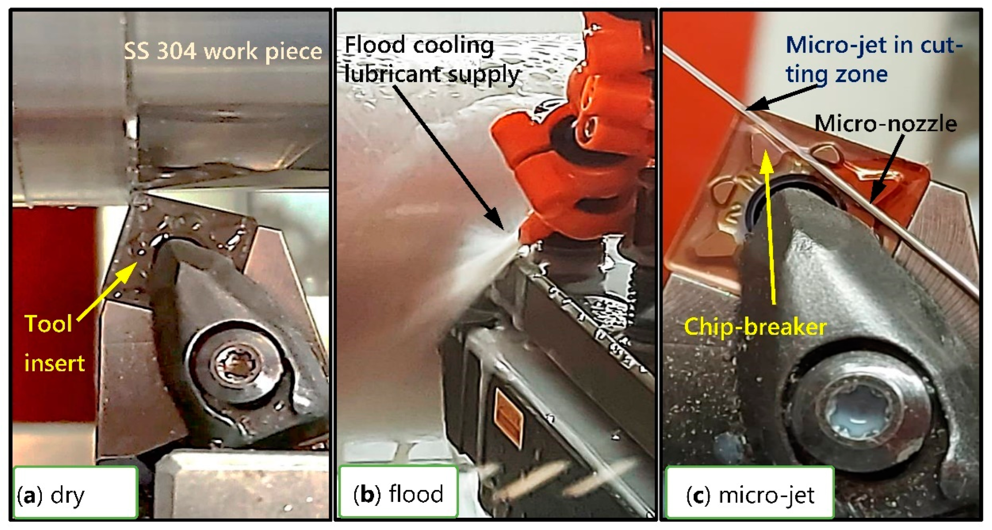
The said work material and the cutting tools are used in the aimed study in a 25 kW chuck capacity up to 2500 rpm, on a heavy-duty precision CNC lathe, ECOMET E 300, made in Austria. The normal flood cooling formed with industrial-grade operator-friendly semi-synthetic (chlorine-free) water-soluble oil (Miles Kool Sol SS B, product of Miles Lubricants made in the USA) mixed with water (1:20) is provided in the machining zone by using a 0.37 kW centrifugal pump having a 38 m water head capacity at a flow rate of ~35 L/h. The micro-jet of the same lubricant is pushed in the metal cutting zone at ~4 bar of pressure and ~2.2 L/h of flow rate through a stainless-steel micro-nozzle of the inner dia. 0.2 mm along the chip groove. The schematic view of the micro-jet setup (pneumatic) circuit diagram and the micro-jet supply mechanism are given in Figure 5a,b, respectively.
The advantage of this micro-jet system is that the lubricant/coolant can precisely pass through the chip groove to the cutting zone. The flow rate of the MQL is controllable to less than 1/10th of the flood cooling rate by changing the nozzle dia., mixing ratio of air/gas:(water: oil/solid lubricant), etc. The system pressure can be changed from ~4 bar to ~100 bar. High pressure might be more effective to approach the lubricant in the machining zone, but it increases the flow rate of the coolant. The mixing of air in the coolant flow can reduce the lubricant flow rate significantly but makes a flow of mist jet instead of the liquid jet. The inset views of dry, flood cooling lubrication, and micro-jet MQL delivery are shown in Figure 6a–c, sequentially. The process parameters and responses in this study are given in Table 4 below.
The lubricant micro-jet is focused on the metal cutting zone parallel to the rake surface and through the chip-breaker gaps along the chip groove, as shown in 
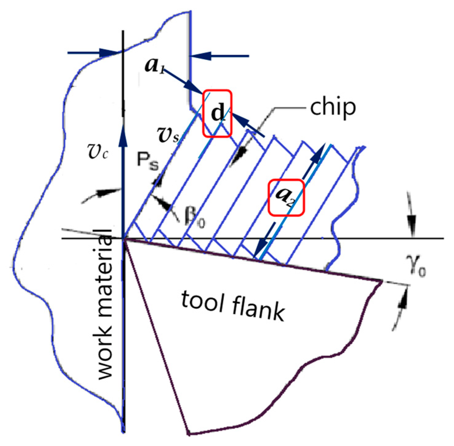
Figure 6c. The mechanism of material removal in turning of this present study is shown in Figure 7 where the chip shear plane thickness ‘d’ and chip thickness ’a2’ are indicated for the study. The referred equation, ‘ξ = a2/a1’ [
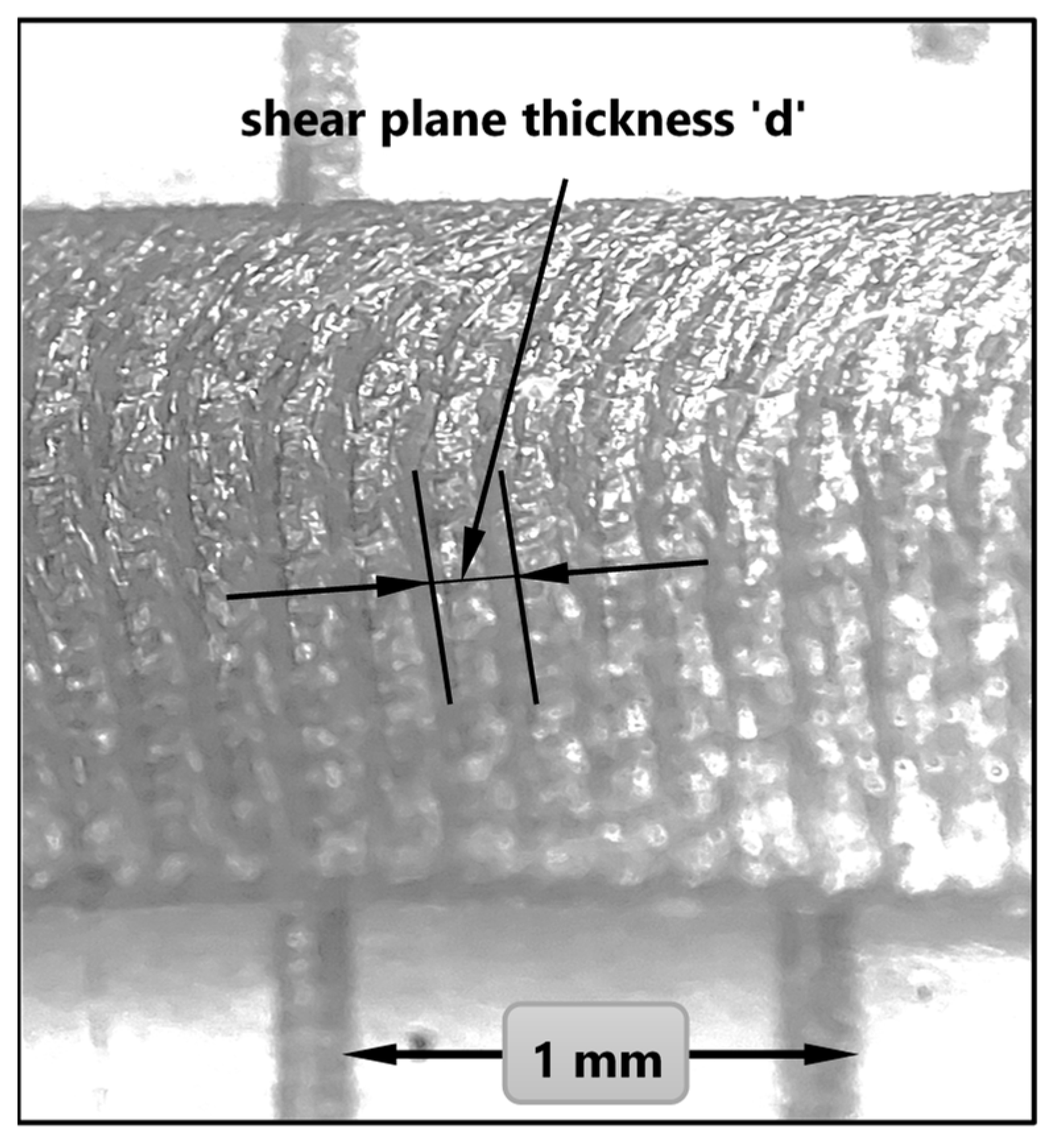
5], is effective to perform a machinability study. The method of measuring ‘d’ is depicted in Figure 8.
In this present study, the relative forces and specific energy requirements for machining are realised by measuring ‘ξ’ and shear strain (τs), which is inversely proportional to shear plane thickness ‘d’. At a constant depth, more chip thickening means more force or energy required to complete the machining work, which is indicated by a larger value of ‘ξ’. Consequently, it is always preferable to lower the values of ‘ξ’ without sacrificing productivity or metal removal rate (MRR). The chip reduction coefficient is observed less than or equal to 2 in favourable machining conditions.
All the machining chips in this investigation are collected as samples and examined (shown in Tables 10–15), and the shear plane thickness is measured as shown in Figure 8. In all the cutting trails, new cutting tool edges are used after every experimental run. The cutting edges are examined under Mitutoyo tool maker’s microscope, Japan that is fitted with a DeltaPix™ digital metallographic camera with software. The observed tool-edge chipping and cutting-edge breaking (in some cases) are shown in Figure 9. The chip thickness is measured by using a digital Vanier Caliper made by BAKER, India.

2.1. Response Surface Methodology (RSM) and Design of Experiment

To model and analyse issues when a response of concern is influenced by numerous variables, the Response Surface Methodology (RSM) adopts both mathematical and statistical methodologies. RSM makes an effort to examine how the independent variables affect a particular reliant variable (response). The independent variables denoted by x 1 , x 2 , ……, x k are presumed to be continuous and can be controlled with negligible error. It is assumed that the response Y is a random variable. The response Y can be visualised as a function of the two independent variables x1 and x2 in the following way [35]:
Y = f ( x 1 , x 2 ) + ε
where ‘ε’ represents an error component.
To roughly represent the surface surrounding a curvature, a second- or higher-order response surface model is required. A second-order response surface model, which can be expressed by Equations (1) and (2), is suitable in the majority of cases:
Y = b 0 + i = 1 k b i x i + i = 1 k b i i x i 2 + i k j k b i j ( i < j ) x i x j + ε
The parameter settings for conducting statistical analyses on the level of importance of process parameters and their interactions are displayed in Table 5.

2.2. Artificial Neural Network (ANN) Model

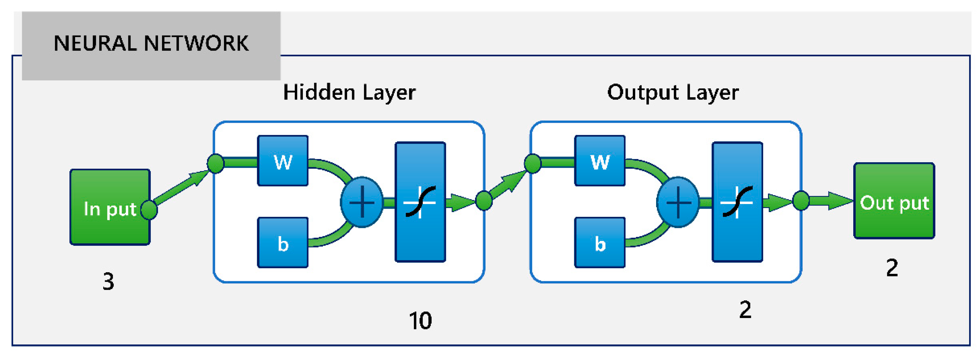
An ANN is a non-linear plotting system that functions like the human brain. It includes three interconnected layers, each of which contains one or more neurons. The input layer, often known as the first layer, is where the model receives its numerical input. One variable in this definition defines one neuron. The information is received by the concealed or hidden layer, which is the second layer, and is then processed. The output is provided by the output layer, which is linked to the hidden layer by synaptic weights (s). The ANN model’s accuracy depends on the type of training algorithm, configuration, various functions, weights, and biases. The notation ‘3-n-2’ denotes the input layer’s three neurons, the hidden layer’s n (unknown) neurons, and the output layer’s two neurons. Three neurons serve as inputs for the environment, cutting speed, and feed, while two neurons serve as outputs for the chip reduction coefficient and plane thickness. Out of 48 experimental datasets, 14 sets are used for model testing and validation, while 34 sets are used for training. The model for predicting chip behaviour is developed, trained, and tested using MATLAB R2015a’s ‘nnstart’ wizard. Mean square error (MSE) is used to measure performance during training, and mean absolute percentage error (MAPE) is used to measure performance during testing, as illustrated in Equations (3) and (4).
M S E = 1 N n = 1 N ( A c t u a l P r e d i c t e d ) 2
M A P E = 1 N n = 1 N A c t u a l P r e d i c t e d A c t u a l × 100

3. Results

The experimental results of Y1 (ξ) and Y2 (d) along with the design matrix are tabulated in Table 6.

4. Discussion

In the present work, two full quadratic equations—one for the chip reduction coefficient (ξ) and another for chip shear plane thickness (d), in the form of Equation (1), are expressed by using the response surface method and are presented in Equation (5) and (6) respectively. The experimental values of responses corresponding to control variables are incorporated into the RSM model in Minitab 14.0.
Y 1 ( ξ ) =   1.9436 + 0.1752 E 0.0138 V c 2.1198 f + 0.05907 V c 2 0.0607 EV c 1.7021 E f
Y 2 ( d ) =   108.976 + 1.158 E 23.877 V c + 16.669 f + 15.823 V c 2 + 0.172 EV c + 0.645 E f
The effects of different input parameters on the dependent responses (chip reduction coefficient and plane thickness) are evaluated by the analysis of variance (ANOVA). The results of ANOVA for the chip reduction coefficient (ξ) and chip shear plane thickness (d) are tabulated in Table 7 and Table 8, respectively. The ANOVA table consists of a sequential sum of a square from which the percentage contribution of factors is determined, F-value and P-value. A factor’s importance is shown by the P-value, which has a 95% confidence level. The greater relative importance of that component is indicated by a larger F-value.
For the RSM quadratic model for Y1 and Y2, the environment, cutting speed, and feed are all statistically significant as the P-value is less than 0.05. It also depicts that the contribution of linear terms for both models is 86.55% and 88.67%, respectively, of the total variation.
The square terms of cutting speed are also significant for both cases. The adjusted R2 values of the chip reduction coefficient (ξ) and chip shear plane thickness (d) are 0.928 and 0.986, respectively, and both values are close to 1, indicating that all the models are adequate.
The normal probability plots of the residuals (red dots) and the plots of the residuals vs. the predicted response for ‘ξ and ‘d’ are revealed in Figure 10 and Figure 11, respectively. According to a review of the plots in Figure 10a and Figure 11a, the residuals typically fall on a straight line, indicating that the errors are distributed regularly. In addition, Figure 10b and Figure 11b expose that they have no clear pattern and unusual structure. This suggests that the offered models are suitable and that the assumptions of independence and constant variance are not violated.
Plots of main effects are made to examine the impacts of the parameters on the chip reduction coefficient (ξ) and chip shear plane thickness (d). As may be seen from Figure 12, the environment, cutting speed, and feed are the significant factors in the chip thickness coefficient.
These graphs indicate that as the three input parameters increase, the chip thickness coefficient value sharply decreases. Figure 13 (a) environment, (b) cutting speed, and (c) feed show the effects on chip shear plane thickness. The R2 is equal to 0.99948 and 0.99646 for validation and testing, respectively. At this point, the training process is paused, and the ANN model’s two responses (outputs) are predicted using all 48 experimental data. The ANN model’s predicted values and the experimental values are thought to be in good agreement.
The surface plot of ξ versus cutting parameters at constant environment, cutting speed, and feed are given in Figure 14a–c respectively. Similarly, the surface plot of ‘d’ versus cutting parameters at the constant environment, cutting speed, and feed constant are shown in Figure 15a–c respectively.
Figure 13a shows that the shear plane thickness ‘d’ is not significantly affected by environmental conditions. The shear plane thickness might be most affected by intrinsic or similar issues but not so much affected by extrinsic issues such as environments. The effect of speed on ‘d’ is shown in Figure 13b and Figure 15c; as Vc increases, the cutting temperature increases and softens the material, which may reduce ‘d’, and as the feed increases, the ‘d’ value increases proportionately, as in Figure 13c and Figure 15a.
Table 9 shows some experimental and anticipated regression model values for the parameters chip reduction coefficient ‘ξ’ and plane thickness ‘d’. Both values clearly show that the experimental values and the projected values are in good agreement with one another.
For the ANN model design, a 10-hidden-neuron ANN architecture, as shown in Figure 16, is chosen. Training is the initial phase of the ANN.
In this work, a feed-forward multi-layer neural network for both responses, chip reduction coefficient (ξ) and plane thickness (d), having the ‘3-10-2′ architecture is adopted. In this study, the smaller network dataset is trained using the Levenberg-Marquardt algorithm. Although it needs more memory than other algorithms for larger datasets, Train Levenberg-Marquardt (TrainLM) is frequently the quickest backpropagation method in the simulation programme and is strongly advised as a first-choice supervised technique. By utilising a back-propagation technique to minimise global error, adequate performance levels are attained. The backpropagation algorithm is a learning method that modifies ANN weights by propagating weight changes from output to input neurons. When the target level of performance is attained, network training is terminated. To make decisions for the evaluation of output, the weights generated during this stage are used. In this inquiry, ANN training, validation, and testing are conducted using the MATLAB toolbox. The network is trained using a collection of experimental values to create an ANN model. After a successful training session, the network is utilised to forecast the replies for testing and validation. 
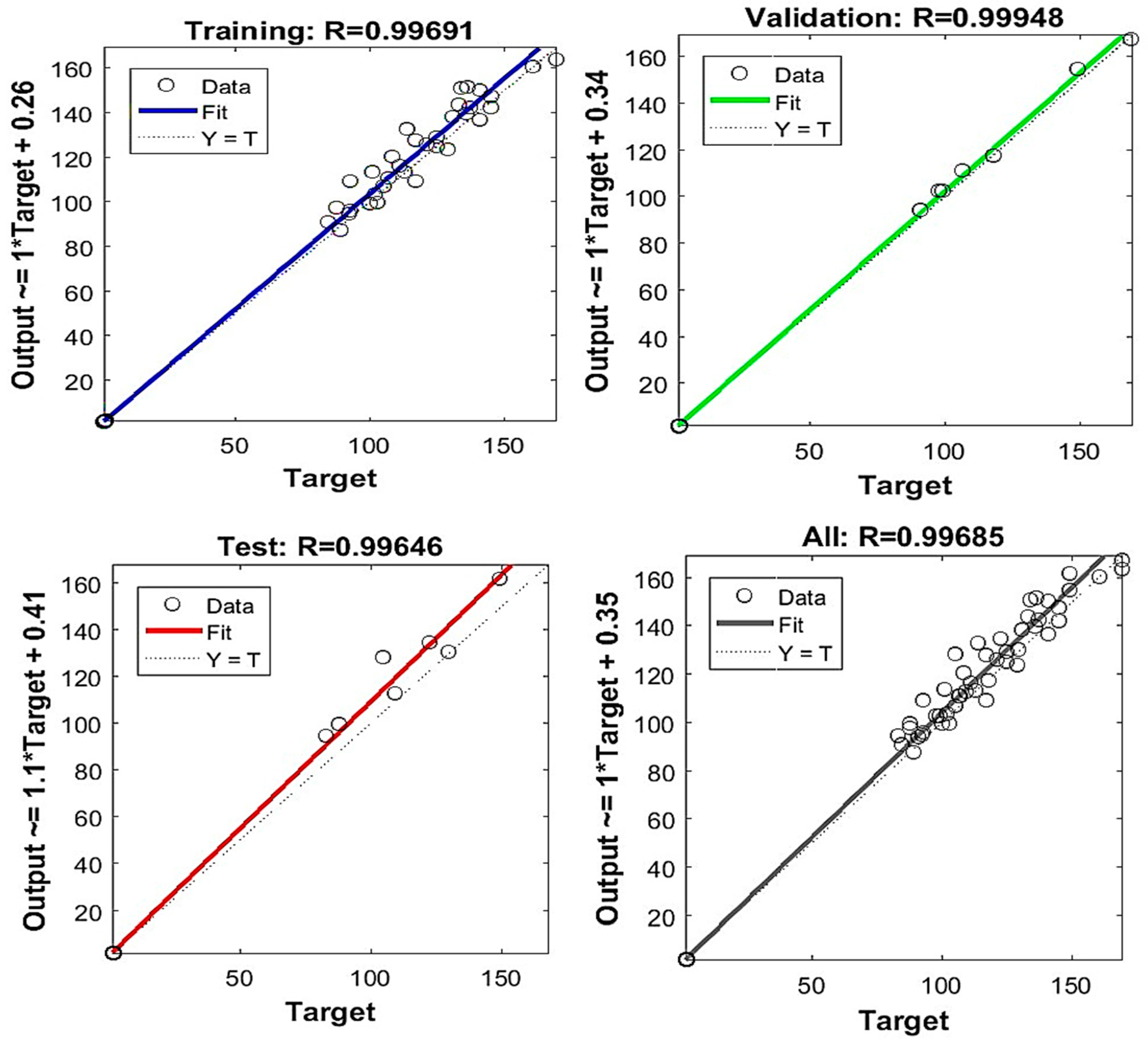
Figure 17 displays the ANN results. It is clear from Figure 18 that all the experimental and predicted values during training coincide perfectly on the regression line, which makes R2 = 0.99691 in training. The R2 is equal to 0.99948 and 0.99646 for validation and testing, respectively. At this point, the training process is paused, and the ANN model’s two responses (outputs) are predicted using all 48 experimental data. The ANN model’s predicted values and the experimental values are thought to be in good agreement.

4.1. Chip Characteristics Study by Visual Observation

The study of chip characteristics is conducted under visual observation of chip types and chip morphology. The machining chip types as collected during machining in dry, micro-jet, and flood cooling are tabulated in Table 10, Table 11 and Table 12 below, respectively. The chip morphology of the same machining chips is given in Table 13, Table 14 and Table 15, sequentially.
The observation from Table 10, Table 11 and Table 12 indicates that continuous chips are more evident in flood cooling as compared to a micro-jet environment. Eventually, short chips are common in all the machining conditions (dry, micro-jet, and flood cooling), in the higher range of speed and feed combinations (as shown with red marks in the figures of Table 10, Table 11 and Table 12).
In Table 13, Table 14 and Table 15, the chip colour changes (which might be due to oxidation) are most prominent in dry and micro-jet machining. The higher machining temperature causes more oxidation of hot chip surfaces, which results in colour change [36,37]. It is observed in Table 15 that the change in chip colour is less in the flood cooling condition. It indicates that the overall cooling is better in this condition.
The short-length chips are mainly found in Table 10 and Table 11 due to the strain occurrence in chips that is evident in Table 13 and Table 14 for dry and micro-jet machining conditions, respectively. The inference from the overall observations in Table 10, Table 11, Table 12, Table 13, Table 14 and Table 15 indicates that the flood cooling condition is more comfortable in MRR as compared to dry and micro-jet MQL.

4.2. Cutting Tool Health Observation

Cutting tool conditions are monitored and BUEs, tool-edge chipping, and tool-edge breakings are noticed in some cases, which are highlighted in Table 6. BUEs occur significantly less in dry and micro-jet cooling conditions, but BUEs and edge chipping predominantly occur in the flood cooling condition. Edge breaking is also observed in the same condition. The flood cooling might not be favourable for cutting-tools–workpiece interfaces. It was also observed from the investigation of Dhar et al. 2005 [38], in machining C-60 steel, that the uncoated carbide tool inserts are sometimes more prone to wear in wet conditions as compared to dry and cryogenic environments. Shaw, 2005 [39] mentioned that the TiAlN-coated tool performs better in dry high-speed machining. The PVD (TiAlN + TiAiN)-coated carbide (SNMG) tool inserts, used in this investigation, might be chemically stable at high temperatures in dry conditions. However, they might not be compatible with the heating and cooling effect in wet conditions, which may result in higher chances of BUEs, edge chipping, and edge breaking.

4.3. Machinability by Considering Ease of MRR and Tool Health

The machinability of SS 304 is analysed by the output responses and tool health observations. Tool life (inverse with BUE formation, edge chipping, and edge breaking) and ease of MRR (inverse with ‘ξ’) are some main considerations for the machinability study. For the prediction of machinability (in this investigation), the chip reduction coefficient and cutting-tool-edge chipping phenomena are plotted based on dry, micro-jet, and flood cooling environments in Figure 18.
It is clear from Figure 18 that cutting is comfortable in flood cooling conditions but tool (SNMG-coated carbide) health suffers severely from the flood coolant due to predominant edge chipping, which might be caused due to BUE formation during machining. Rather, the coated carbide cutting tool performs better in dry and micro-jet cooling conditions.
By considering the ease of MRR and cutting tool life, micro-jet cooling conditions seem to be the optimum one, which has a cheaper running cost than flood cooling and is eco-friendly.

5. Conclusions

The cost-effective machinability study of highly useful material SS-304 is essential in general machining industries. The main findings of this experimental investigation and analysis are as follows:
  • The higher feeds and high cutting speeds of all the machining conditions (dry, flood cooling, and MQL) produce similar short-length chips. It seems that the MQL and flood cooling have less influence on metal cutting at higher feed rates and cutting speeds.
  • The favourable cutting of SS 304 takes place under flood cooling at the highest cutting speeds (140 m/min) and highest feed rate (0.16 mm/rev). BUEs, cutting-edge chipping, and edge breaking are mostly observed in the PVD-coated (TiAlN + AlCr2O3 +TiAiN) carbide cutting tool inserts in flood cooling. It indicates that flood cooling is an unfavourable environment for the cutting tool material.
  • The optimum machinability is found in the micro-jet (SQL) condition by considering MRR, tool health, machining cost, and biological safety.
  • Attention and care should be taken in the selection of a nanofluid as MQL in machining because some nanofluids may be more fatal than abandoning the use of flood cooling.
  • The chip reduction coefficient and plane thickness models are found adequate by using the response surface methodology technique.
  • The face-centred Central Composite Design (CCD) methodology in RSM delivers a good coefficient of regression values of R2= 0.932 and R2 = 0.988 for the chip reduction coefficient (ξ) and plane thickness measurement (d), respectively. It indicates that the preferred output response model is fitted closely and effectively with the actual experimental result data.
  • The R2 value for ANN architecture is superior and significant at a 95% confidence level. The overall R2 value (0.99685) is found with the use of 3-n-2 architecture.
The extended machinability study of SS-304 can be investigated further using this cryo-micro-jet (MQL) system at high operating pressure and a higher range of cutting speed and feed rate by using an uncoated carbide tool.

Author Contributions

Conceptualization, B.H. and H.J.; methodology, B.H.; software, H.J.; validation, H.J., formal analysis, B.H.; investigation, B.H.; resources, N.A.A. and A.A.; data curation, B.H., B.L., and H.J.; writing—original draft preparation, B.H; writing—review and editing, H.J., N.A.A., and A.A.; visualization, B.L., N.A.A., H.J., and A.A.; supervision, B.H., N.A.A., and A.A; project administration, N.A.A., and A.A.; funding acquisition, B.H., B.L, N.A.A., and A.A. All authors have read and agreed to the published version of the manuscript.

Funding

This research received no external funding.

Data Availability Statement

Not applicable.

Acknowledgments

The authors are thankful to Imam Mohammad Ibn Saud Islamic University (IMSIU), Riyadh-11432, Saudi Arabia for providing all kinds of internal support for conducting this experimental investigation.

Conflicts of Interest

The authors declare no conflict of interest.

Nomenclature

SLSolid lubricantsSQLSmall-quantity lubrication
NPsNanoparticlesMQLMinimum-quantity lubrication
Al2O3Aluminium oxideMoS2Molybdenum disulphide
SiO2Silicon dioxidehBNHexagonal boron nitride
WS2Tungsten disulphidePVDPhysical vapour deposition
ZrO2Zirconium oxideTiAlNTitanium aluminium nitride
ξChip reduction coefficientCNTCarbon nanotube
a1uncut chip thicknessLN2Liquid nitrogen
a2chip thicknessCBNCubic Boron Nitride
BUEBuilt-up-edgeANNArtificial neural network
VcCutting velocityRSMResponse surface methodology
ffeed ratePCDPolycrystalline diamond

References

  1. Kalpakjian, S.; Schmid, S.R.; Sekar, K.S.V. Manufacturing Engineering and Technology, 7th ed.; Pearson: New Jersey, NJ, USA, 2014; Volume 7, ISBN 978-981-06-9406-7. [Google Scholar]
  2. Naves, V.T.G.; Da Silva, M.B.; Da Silva, F.J. Evaluation of the effect of application of cutting fluid at high pressure on tool wear during turning operation of AISI 316 austenitic stainless steel. Wear 2013, 302, 1201–1208. [Google Scholar] [CrossRef]
  3. Walker, T. The MQL Handbook; Unist, Inc.: Grand Rapids, MI, USA, 2013. [Google Scholar]
  4. Su, G.; Xiao, X.; Du, J.; Zhang, J.; Zhang, P.; Liu, Z.; Xu, C. On cutting temperatures in high and ultrahigh-speed machining. Int. J. Adv. Manuf. Technol. 2020, 107, 73–83. [Google Scholar] [CrossRef]
  5. Chattopadhyay, A.B. Mchining and Machine Tools, 1st ed.; Wiley India Pvt. Ltd.: New Delhi, India, 2011; ISBN 8126530987. [Google Scholar]
  6. Safie, N.S.S.; Murad, M.N.; Lih, T.C.; Azmi, A.I.; Wan Hamzah, W.A.; Danish, M. Roles of Eco-Friendly Non-Edible Vegetable Oils in Drilling Inconel 718 through Minimum Quantity Lubrication. Lubricants 2022, 10, 211. [Google Scholar] [CrossRef]
  7. Canter, N. Tribology & Lubricant Technology; United States Cutting Tool Institute: Cleveland, OH, USA, 2009; pp. 40–44. [Google Scholar]
  8. Aslan, A.; Salur, E.; Kuntoğlu, M. Evaluation of the Role of Dry and MQL Regimes on Machining and Sustainability Index of Strenx 900 Steel. Lubricants 2022, 10, 301. [Google Scholar] [CrossRef]
  9. Salur, E. Understandings the tribological mechanism of Inconel 718 alloy machined under different cooling/lubrication conditions. Tribol. Int. 2022, 174, 107677. [Google Scholar] [CrossRef]
  10. Baldin, V.; da Silva, L.R.R.; Gelamo, R.V.; Iglesias, A.B.; da Silva, R.B.; Khanna, N.; Machado, A.R. Influence of Graphene Nanosheets on Thermo-Physical and Tribological Properties of Sustainable Cutting Fluids for MQL Application in Machining Processes. Lubricants 2022, 10, 193. [Google Scholar] [CrossRef]
  11. Hamran, N.N.N.; Ghani, J.A.; Ramli, R.; Haron, C.H.C. A review on recent development of minimum quantity lubrication for sustainable machining. J. Clean. Prod. 2020, 268, 122165. [Google Scholar] [CrossRef]
  12. Eric, S. Machinability of Stainless Steel. Available online: https://www.machiningdoctor.com/machinability/stainless-steel-2/ (accessed on 17 October 2022).
  13. Forum, I.S.S. Stainless Steel in Figures. 2019. Available online: https://www.worldstainless.org/Files/issf/non-image-files/PDF/ISSF_Stainless_Steel_in_Figures_2019_English_public_version.pdf (accessed on 18 October 2022).
  14. Charles, J. Past, Present and Future of the Duplex Stainless. Available online: https://www.worldstainless.org/Files/issf/non-image-files/PDF/Pastpresentandfutureoftheduplexstainlesssteels.pdf (accessed on 10 October 2022).
  15. Usca, Ü.A.; Uzun, M.; Şap, S.; Giasin, K.; Pimenov, D.Y.; Prakash, C. Determination of machinability metrics of AISI 5140 steel for gear manufacturing using different cooling/lubrication conditions. J. Mater. Res. Technol. 2022, 21, 893–904. [Google Scholar] [CrossRef]
  16. Sen, B.; Mia, M.; Krolczyk, G.M.; Mandal, U.K.; Mondal, S.P. Eco-Friendly Cutting Fluids in Minimum Quantity Lubrication Assisted Machining: A Review on the Perception of Sustainable Manufacturing; Korean Society for Precision Engineering: Seoul, Republic of Korea, 2021; Volume 8, ISBN 4068401900158. [Google Scholar]
  17. Race, A.; Zwierzak, I.; Secker, J.; Walsh, J.; Carrell, J.; Slatter, T.; Maurotto, A. Environmentally sustainable cooling strategies in milling of SA516: Effects on surface integrity of dry, flood and MQL machining. J. Clean. Prod. 2021, 288, 125580. [Google Scholar] [CrossRef]
  18. Varadarajan, A.S.; Philip, P.K.; Ramamoorthy, B. Investigations on hard turning with minimal cutting fluid application (HTMF) and its comparison with dry and wet turning. Int. J. Mach. Tools Manuf. 2002, 42, 193–200. [Google Scholar] [CrossRef]
  19. Pervaiz, S.; Ahmad, N.; Ishfaq, K.; Khan, S.; Deiab, I.; Kannan, S. Implementation of Sustainable Vegetable-Oil-Based Minimum Quantity Cooling Lubrication (MQCL) Machining of Titanium Alloy with Coated Tools. Lubricants 2022, 10, 235. [Google Scholar] [CrossRef]
  20. Makhesana, M.A.; Patel, K.M.; Bagga, P.J. Evaluation of Surface Roughness, Tool Wear and ChipMorphology duringMachining of Nickel-Based Alloy under Sustainable HybridNanofluid-MQL Strategy. Lubricants 2022, 10, 315. [Google Scholar] [CrossRef]
  21. Duc, T.M.; Long, T.T.; Chien, T.Q. Performance Evaluation of MQL Parameters Using Al2O3 and MoS2 Nanofluids in Hard Turning 90CrSi. Lubricants 2019, 7, 40. [Google Scholar] [CrossRef] [Green Version]
  22. Hoet, P.H.M.; Brüske-hohlfeld, I.; Salata, O.V. Nanoparticles—Known and unknown health risks. J. Nanobiotechnol. 2004, 2, 12. [Google Scholar] [CrossRef] [Green Version]
  23. Ye, M.; Shi, B. Zirconia Nanoparticles-Induced Toxic Effects in Osteoblast-Like 3T3-E1 Cells. Nanoscale Res. Lett. 2018, 13, 353. [Google Scholar] [CrossRef] [PubMed] [Green Version]
  24. Najahi-Missaoui, W.; Arnold, R.D.; Cummings, B.S. Safe nanoparticles: Are we there yet? Int. J. Mol. Sci. 2021, 22, 385. [Google Scholar] [CrossRef] [PubMed]
  25. Nouzil, I.; Eltaggaz, A.; Pervaiz, S.; Deiab, I. Toxicity Analysis of Nano-Minimum Quantity Lubrication Machining—A Review. Lubricants 2022, 10, 176. [Google Scholar] [CrossRef]
  26. Hazardous Substance Fact Sheet. Available online: https://www.nj.gov/health/eoh/rtkweb/documents/fs/2891.pdf (accessed on 3 November 2022).
  27. Xu, Z.; Lu, J.; Zheng, X.; Chen, B.; Luo, Y.; Nauman, M.; Huang, B.; Xia, X.; Pan, X. A critical review on the applications and potential risks of emerging MoS 2 nanomaterials. J. Hazard. Mater. 2020, 399, 123057. [Google Scholar] [CrossRef]
  28. Tsai, L.W.; Lin, Y.C.; Perevedentseva, E.; Lugovtsov, A.; Priezzhev, A.; Cheng, C.L. Nanodiamonds for medical applications: Interaction with blood in vitro and in vivo. Int. J. Mol. Sci. 2016, 17, 5–9. [Google Scholar] [CrossRef] [Green Version]
  29. ANI Swallowed Nano-Diamonds Could Illuminate Your Ailments. Available online: https://www.thehindu.com/sci-tech/health/medicine-and-research/Swallowed-nano-diamonds-could-illuminate-your-ailments/article15907508.ece (accessed on 9 November 2022).
  30. Reis, R.L. Encyclopedia of Tissue Engineering and Regenerative Medicine, 1st ed; Elsevier Inc.: Amsterdam, The Netherlands, 2019; ISBN 9780128137000. [Google Scholar]
  31. Shah, R.; Shirvani, K.A.; Przyborowski, A.; Pai, N.; Mosleh, M. Role of Nanofluid Minimum Quantity Lubrication (NMQL) in Machining Application. Lubricants 2022, 10, 266. [Google Scholar] [CrossRef]
  32. Luanpitpong, S.; Wang, L.; Rojanasakul, Y. The effects of carbon nanotubes on lung and dermal cellular behaviors. Nanomedicine 2014, 9, 895–912. [Google Scholar] [CrossRef] [PubMed] [Green Version]
  33. Starost, K.; Frijns, E.; Van Laer, J.; Faisal, N.; Egizabal, A.; Elizetxea, C.; Nelissen, I.; Blázquez, M.; Njuguna, J. The effect of nanosilica (SiO2) and nanoalumina (Al2O3) reinforced polyester nanocomposites on aerosol nanoparticle emissions into the environment during automated drilling. Aerosol Sci. Technol. 2017, 51, 1035–1046. [Google Scholar] [CrossRef] [Green Version]
  34. Goralka, C.; Bridges, J.; Jahan, M.; Sidebottom, M.; Cameron, T.; Lu, Y.; Ye, Z. Friction and Wear Reduction of Tungsten Carbide and Titanium Alloy Contacts via Graphene Nanolubricant. Lubricants 2022, 10, 272. [Google Scholar] [CrossRef]
  35. Montgomery, D.C. Design and Analysis of Experiments, 10th ed.; WILEY: New York, NY, USA, 2019; ISBN 9781119492443. [Google Scholar]
  36. Bhattacharya, A. Metal Cutting: Theory and Practice, 1st ed.; New Central Book Agency: Kolkata, India, 2012; ISBN 8173812004. [Google Scholar]
  37. Chen, S.H.; Luo, Z.R. Study of using cutting chip color to the tool wear prediction. Int. J. Adv. Manuf. Technol. 2020, 109, 823–839. [Google Scholar] [CrossRef]
  38. Dhar, N.R.; Islam, S.; Kamruzzaman, M.; Paul, S. Wear behavior of uncoated carbide inserts under dry, wet and cryogenic cooling conditions in turning C-60 steel. J. Brazilian Soc. Mech. Sci. Eng. 2006, 28, 146–152. [Google Scholar] [CrossRef]
  39. Shaw, M.C. Metal Cutting Principles, 2nd ed.; Oxford University Press: Oxford, UK, 2005; ISBN 0195142063. [Google Scholar]
Figure 1. Typical tree diagram of end-user manufacturing costs in machining [7].
Lubricants 10 00359 g001
Figure 2. Categories of MQL advancements with new scopes [11].
Lubricants 10 00359 g002
Figure 3. Stainless-steel use per sector in 2018 [13].
Lubricants 10 00359 g003
Figure 4. The (a) work specimen SS 304 rod installed in the CNC lathe; (b) tool insert and tool holder details.
Lubricants 10 00359 g004
Figure 5. Schematic view of (a) micro-jet setup circuit diagram and (b) micro-jet supply mechanism.
Lubricants 10 00359 g005
Figure 6. (a) Dry machining, (b) flood cooling, and (c) MQL machining condition using micro-jet.
Lubricants 10 00359 g006
Figure 7. Mechanism of material removal considered in this present study.
Lubricants 10 00359 g007
Figure 8. Microscopic view of a chip top surface topography.
Lubricants 10 00359 g008
Figure 9. Microscopic views of (a) BUE, and (b) edge chipping and edge breaking on used PVD (TiAlN + TiAiN)-coated carbide tool inserts.
Lubricants 10 00359 g009
Figure 10. (a) Normal probability plot of residuals; (b) plot of residuals vs. predicted response for chip reduction coefficient.
Lubricants 10 00359 g010
Figure 11. (a) Normal probability plot of residuals; (b) plot of residuals vs. predicted response for plane thickness.
Lubricants 10 00359 g011
Figure 12. Main effects plots of chip reduction coefficient (ξ) vs. (a) environment, (b) cutting speed, and (c) feed.
Lubricants 10 00359 g012
Figure 13. Main effects plots of chip shear plane thickness ‘d’ vs. (a) environment, (b) cutting speed, and (c) feed.
Lubricants 10 00359 g013
Figure 14. Surface plot of chip reduction coefficient (ξ) versus cutting parameters at (a) environment, (b) cutting speed, and (c) feed constant.
Lubricants 10 00359 g014
Figure 15. Surface plot of the plane thickness (d) versus cutting parameters at the (a) environment, (b) cutting speed, and (c) feed constant.
Lubricants 10 00359 g015
Figure 16. ANN structure used for modelling.
Lubricants 10 00359 g016
Figure 17. ANN trained model for the best fitness.
Lubricants 10 00359 g017
Figure 18. Variation in chip reduction coefficient, BUE, and edge chipping in various environments.
Lubricants 10 00359 g018
Table 1. A comparative sustainability of low-speed machining under various environments [7,16,17,18,19,20].
StatusDry MachiningMQL MachiningFlood Cooling
Coolant consumption:No use Very lowHigh coolant consumption
Coolant wastage:No wastage Low wastageHigh wastage
Scrap disposal:The scrap is free from the fluidThe scrap is almost cleanThe scrap has fluid deposition over it
Part cleaning:No part cleaning is requiredNo part cleaning is requiredHigh part cleaning required and subjected to corrosion of machine tool parts/structure
Health issues:SafeAlmost safe (attention is needed before use of nanofluids as MQL)Health hazards such as bronchitis, cancer, suffocation, and breathing problems by the fumes, aerosols, etc.
Power consumption:HighMediumLow
Recurring cost for cutting fluid:NoLow cost by minimising lubricationAs high as almost 16% of the total manufacturing cost
Cutting fluid equipment: No need Special setup requiredFlood coolant pump, nozzle, pipes, etc.
Tool life (HSS or similar):Low IntermediateHigh
Machining temperature:HighMay provide better heat transfer than wet lubrication Lower than dry
Machining surface:AverageImprove surface qualityReduce surface damage
MRR compatibility:LowHighHigh
Table 2. Some NPs in MQL used in machining studies and their related health issues.
Nanofluids (NFs) Unique PropertiesHealth Issues/Safety
Al2O3-NPs:Reduce cutting forceNose, throat, and lung irritation with coughing, wheezing, and shortness of breath [26]
hBN-NPsGood in reducing frictionToxicity increased with longer length [25]
WS2 and MoS2-NPs:Provide good surface finish and lower cutting forces [25]These are transition metal dichalcogenides that exhibit a lower toxicity potential than other NPs [25], but excessive production of such NPs may increase risks for human beings and wildlife/ecosystems [27]
nano-diamond (ND):Reduce cutting forceSafe and biocompatible [28,29,30]
CNTs:Very high thermal conductivity (3000 w/mK) improves cooling effect [31]Lung inflammation, lung fibrosis, and cancer [32].
SiO2-NPs:Reduce cutting forceNot established (airway hyperresponsiveness (AHR) found in the rats) [33]
ZrO2-NPs:Reduce cutting forceBiocompatible but in high concentration may lead to inhibitory effects on osteogenic differentiation [23]
graphene-NPs:0.10% in water can reduce sliding friction up to ~29% [34]Increases health risks such as tumour growth [23]
Table 3. Chemical composition of used SS 304 work material.
Chemical composition of stainless steel—Grade 304
elements:CMnSiPSCrNiFe
weight %:~0.08~2~0.75~0.05~0.03~19.05~11.01balance
Table 4. The experimental process parameters, environment, and responses.
Process ParametersResponses
Cutting Speed (Vc), m/minFeed Rate (f), mm/revEnvironment (E)
80, 100, 120, 1500.08, 0.1, 0.12, 0.16(i) Dry
(ii) Micro-jet (MQL)
(iii) Flood cooling
(a) Chip reduction coefficient (ξ)
(b) Chip shear plane thickness (d)
(c) Tool conditions (edge chipping, tool edge damage, etc.) and chip observations
Depth of cut: 1.5 mm (constant)
Table 5. Experimental parameters and their level in experiment design.
ParametersUnitSymbolLevel
1234
Environment-EDryMicro-jetFlood--
Cutting speedm/minVc80100120150
Feedmm/revf0.080.10.120.16
Table 6. Experimental data obtained from turning operation.
Sl.NoInput FactorsResponses
Environment
(E)
Cutting Speed (m/min) (Vc)Feed (mm/rev)
(f)
Chip Reduction Coefficient (ξ)Chip Shear Plane Thickness
(d) (µm)
1Dry 800.082.386134
2Dry800.12.241141
3Dry800.122.07145
4Dry800.161.98160.319
5Dry1000.082.23105
6Dry1000.12.14113.969
7Dry1000.121.97125
8Dry1000.161.96141
9Dry1200.082.298
10Dry1200.12.05393
11Dry1200.121.87101
12Dry1200.161.87118.017
13Dry1500.082.183
14Dry1500.12.0488
15Dry1500.121.92107
16Dry1500.161.95117
17Micro-jet800.082.385133
18Micro-jet800.12.21136.11
19Micro-jet800.122.062149
20Micro-jet800.161.9169
21Micro-jet1000.082.24106.578
22Micro-jet1000.12.03111
23Micro-jet1000.121.963122.522
24Micro-jet1000.161.85136
25Micro-jet1200.082.2488
26Micro-jet1200.11.96105
27Micro-jet1200.121.9108.186
28Micro-jet1200.161.71131
29Micro-jet1500.082.10989
30Micro-jet1500.11.9291
31Micro-jet1500.121.873102
32Micro-jet1500.161.78121
33Flood 800.082.44129.546
34Flood800.12.2145
35Flood800.122.03149
36Flood800.161.77169
37Flood1000.082.243103
38Flood1000.12.075113.109
39Flood1000.121.9129
40Flood1000.161.69137.127
41Flood1200.082.2493
42Flood1200.12.01499.425
43Flood1200.121.91109.366
44Flood1200.161.559124.935
45Flood1500.082.1884.772
46Flood1500.11.9192.475
47Flood1500.121.78100
48Flood1500.161.63117
Colour code:BUE and Edge chipping off:
Edge breaking:
Table 7. Analysis of variance for chip reduction coefficient (ξ).
SourceDFSeq SSF-Valuep-ValuePercentage Contribution
Regression51.7396106.690.00092.69%
Linear31.62435169.430.00086.55%
Square10.0341910.480.0021.82%
Interaction10.0811224.880.0004.32%
Residual Error 420.13697
Total471.87663
R20.932
R2 (Adj.)0.928
Table 8. Analysis of variance for plane thickness measurement (d).
SourceDFSeq SSF-Valuep-ValuePercentage Contribution
Regression623999.1567.430.00098.81%
Linear321537.81050.650.00088.67%
Square12453.5348.060.00010.10%
Interaction27.80.550.5790.032%
Residual Error 41289.0
Total 4724288.1
R20.988
R2 (Adj.)0.986
Table 9. Comparison of some experimental and predicted values of chip reduction coefficient ‘ξ’ and plane thickness.
Run NoChip Reduction CoefficientPlane Thickness
ExperimentalPredictedExperimentalPredicted
12.3862.37249134131.681
52.232.25298105105.054
102.0532.030619396.296
151.921.90594100.35899.011
201.91.88938169166.088
252.242.185388889.994
301.921.966979192.907
352.032.0168149149.096
401.691.68714137.127140.52
452.182.1491184.77285.063
Table 10. Machining chip types formed during dry machining condition.
Cutting Speed (Vc) m/minFeed (f) mm/rev
0.080.10.120.16
80Lubricants 10 00359 i001Lubricants 10 00359 i002Lubricants 10 00359 i003Lubricants 10 00359 i004
100Lubricants 10 00359 i005Lubricants 10 00359 i006Lubricants 10 00359 i007Lubricants 10 00359 i008
120Lubricants 10 00359 i009Lubricants 10 00359 i010Lubricants 10 00359 i011Lubricants 10 00359 i012
150Lubricants 10 00359 i013Lubricants 10 00359 i014Lubricants 10 00359 i015Lubricants 10 00359 i016
Table 11. Machining chip types formed during micro-jet machining condition.
Cutting Speed (Vc) m/minFeed (f) mm/rev
0.080.10.120.16
80Lubricants 10 00359 i017Lubricants 10 00359 i018Lubricants 10 00359 i019Lubricants 10 00359 i020
100Lubricants 10 00359 i021Lubricants 10 00359 i022Lubricants 10 00359 i023Lubricants 10 00359 i024
120Lubricants 10 00359 i025Lubricants 10 00359 i026Lubricants 10 00359 i027Lubricants 10 00359 i028
150Lubricants 10 00359 i029Lubricants 10 00359 i030Lubricants 10 00359 i031Lubricants 10 00359 i032
Table 12. Machining chip types formed during flood cooling condition.
Cutting Speed (Vc) m/minFeed(f) mm/rev
0.080.10.120.16
80Lubricants 10 00359 i033Lubricants 10 00359 i034Lubricants 10 00359 i035Lubricants 10 00359 i036
100Lubricants 10 00359 i037Lubricants 10 00359 i038Lubricants 10 00359 i039Lubricants 10 00359 i040
120Lubricants 10 00359 i041Lubricants 10 00359 i042Lubricants 10 00359 i043Lubricants 10 00359 i044
150Lubricants 10 00359 i045Lubricants 10 00359 i046Lubricants 10 00359 i047Lubricants 10 00359 i048
Table 13. Machining chips’ morphology observed under dry machining condition.
Cutting Speed (Vc)
m/min
Feed(f) mm/rev
0.080.10.120.16
80Lubricants 10 00359 i049Lubricants 10 00359 i050Lubricants 10 00359 i051Lubricants 10 00359 i052
100Lubricants 10 00359 i053Lubricants 10 00359 i054Lubricants 10 00359 i055Lubricants 10 00359 i056
120Lubricants 10 00359 i057Lubricants 10 00359 i058Lubricants 10 00359 i059Lubricants 10 00359 i060
150Lubricants 10 00359 i061Lubricants 10 00359 i062Lubricants 10 00359 i063Lubricants 10 00359 i064
Table 14. Machining chips’ morphology observed during micro-jet machining condition.
Cutting Speed (Vc) m/minFeed (f) mm/rev
0.080.10.120.16
80Lubricants 10 00359 i065Lubricants 10 00359 i066Lubricants 10 00359 i067Lubricants 10 00359 i068
100Lubricants 10 00359 i069Lubricants 10 00359 i070Lubricants 10 00359 i071Lubricants 10 00359 i072
120Lubricants 10 00359 i073Lubricants 10 00359 i074Lubricants 10 00359 i075Lubricants 10 00359 i076
150Lubricants 10 00359 i077Lubricants 10 00359 i078Lubricants 10 00359 i079Lubricants 10 00359 i080
Table 15. Machining chips’ morphology observed during flood cooling condition.
Cutting Speed (Vc) m/minFeed(f) mm/rev
0.080.10.120.16
80Lubricants 10 00359 i081Lubricants 10 00359 i082Lubricants 10 00359 i083Lubricants 10 00359 i084
100Lubricants 10 00359 i085Lubricants 10 00359 i086Lubricants 10 00359 i087Lubricants 10 00359 i088
120Lubricants 10 00359 i089Lubricants 10 00359 i090Lubricants 10 00359 i091Lubricants 10 00359 i092
150Lubricants 10 00359 i093Lubricants 10 00359 i094Lubricants 10 00359 i095Lubricants 10 00359 i096
Publisher’s Note: MDPI stays neutral with regard to jurisdictional claims in published maps and institutional affiliations.

