Experimental Study on the Lubrication Enhancement of Slider-on-Disc Contact by Stearic Acid Adsorption under Limited Lubricant Supply


Abstract
1. Introduction
2. Experimental Detail
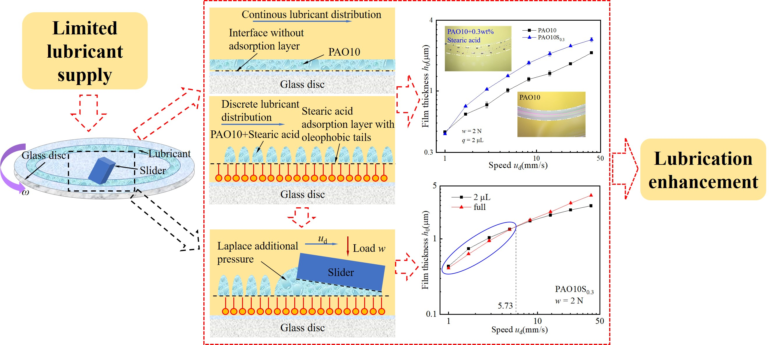
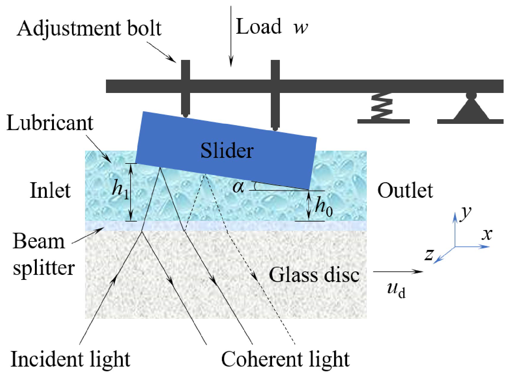
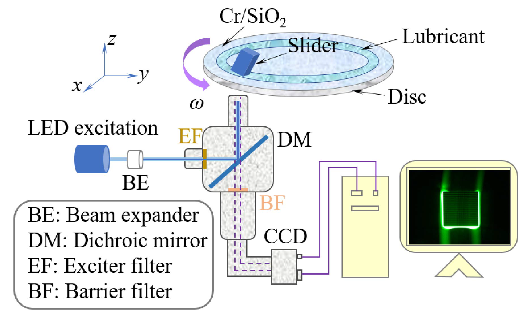
2.1. Experimental Apparatus
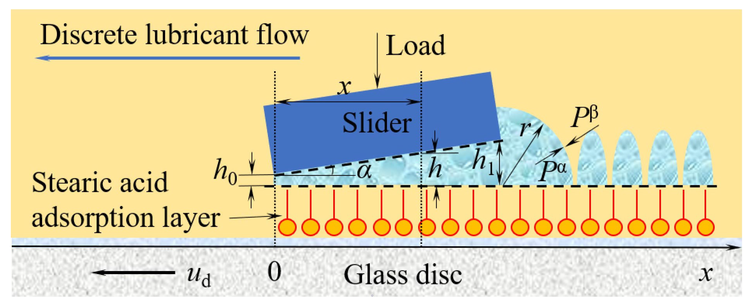
- α is the inclination of the slider (rad);
- λ is the wavelength of incident light (m);
- N is the number of interference fringes;
- n is the refractive index of lubricating medium;
2.2. Materials and Experimental Conditions
3. Results and Discussion
3.1. Effect of Stearic Acid Adsorption on Morphology and Distribution of Lubricants
- The morphology of static lubricants on the lubrication track of the glass disc;
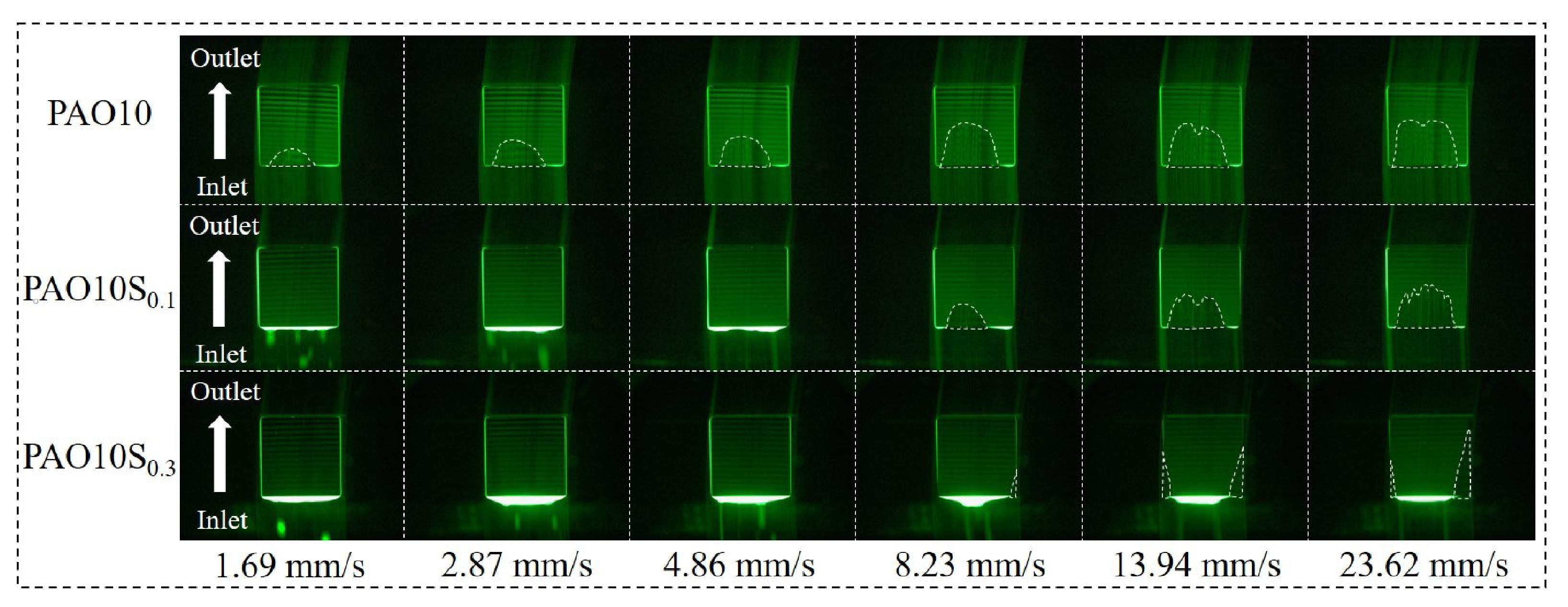
- The morphology of lubricants in the oil reservoir at the slider entrance during the running of the glass disc;
- The distribution of lubricants at the side edge of the slider.
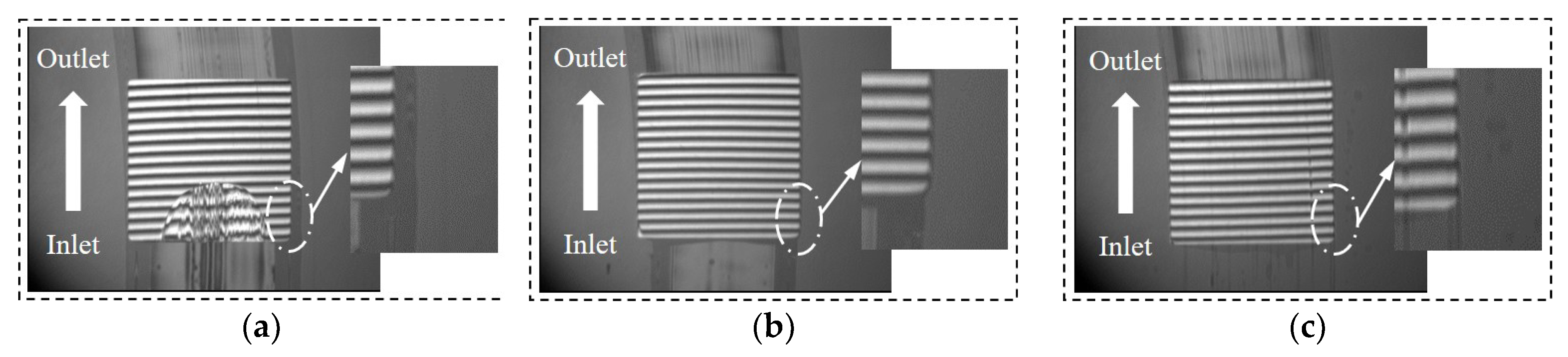
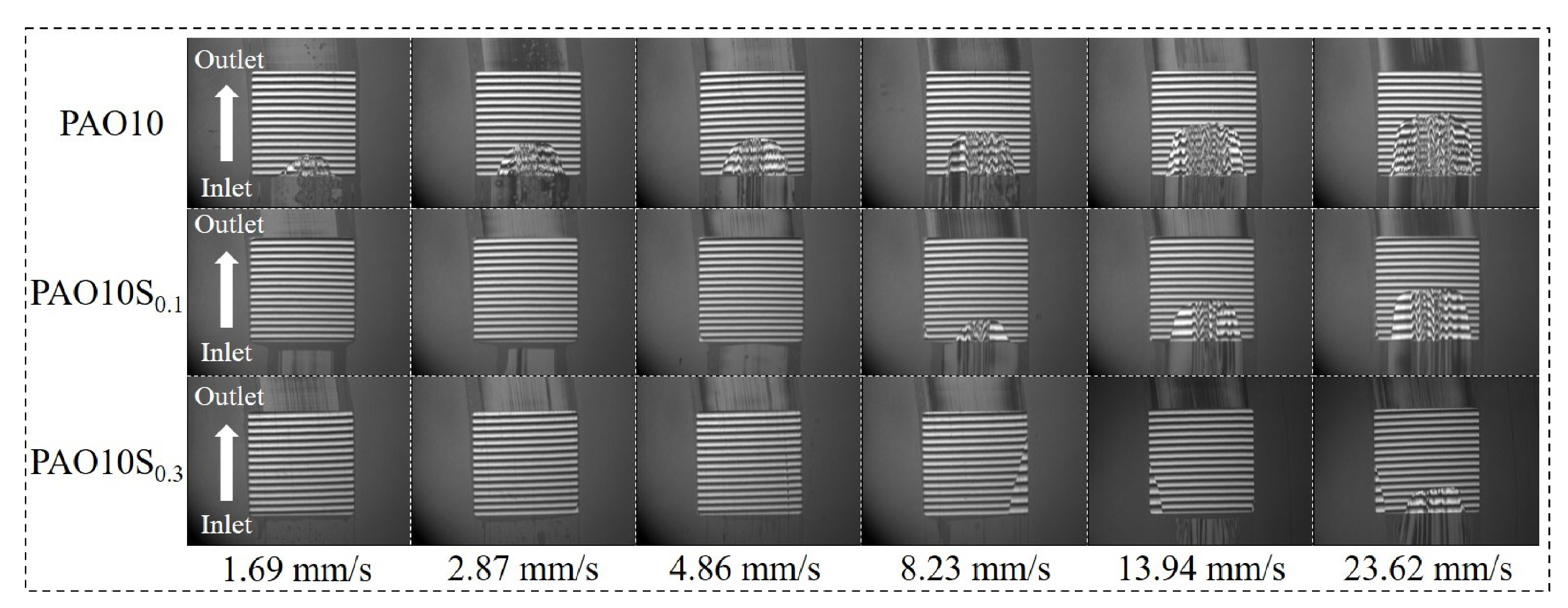
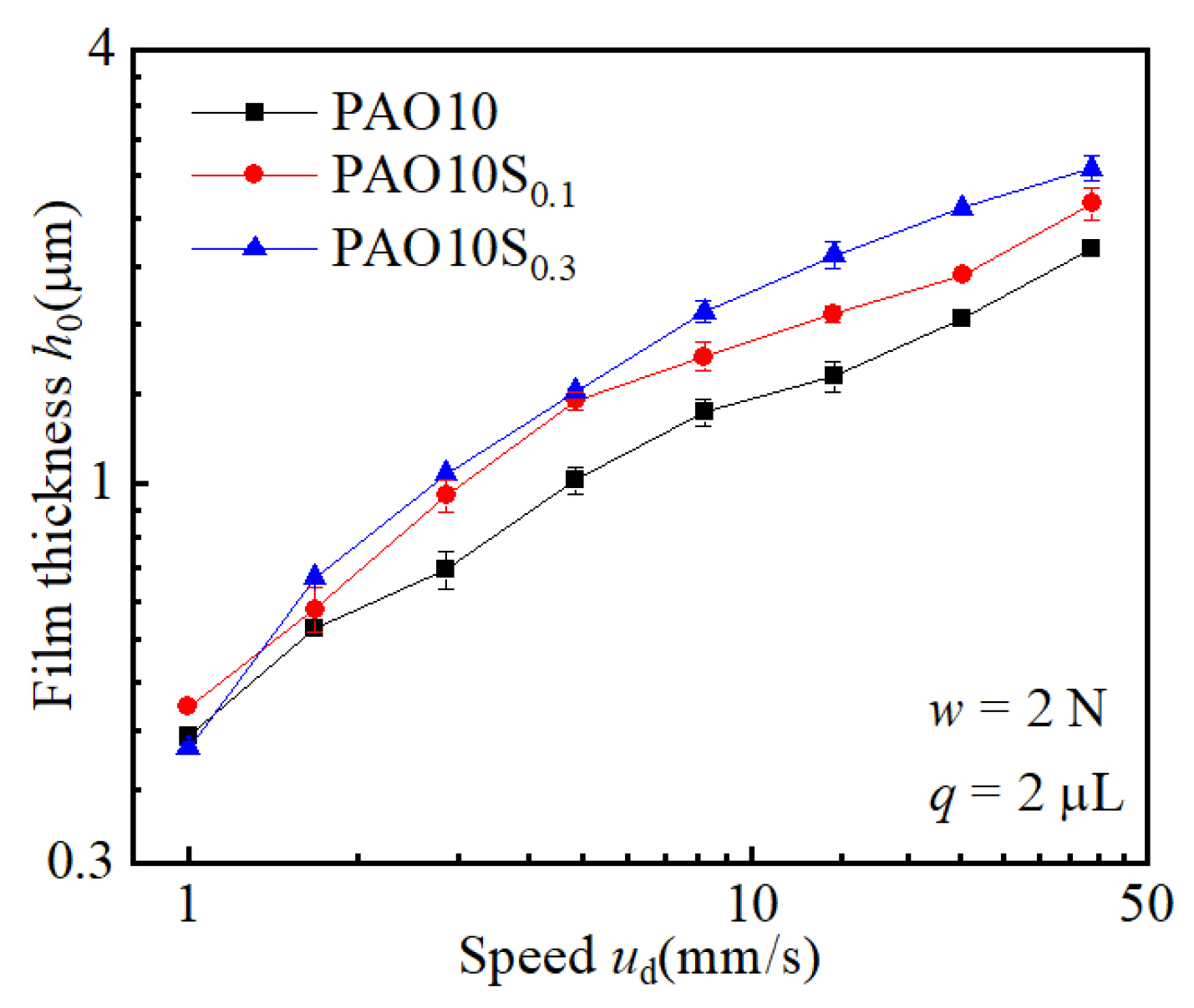
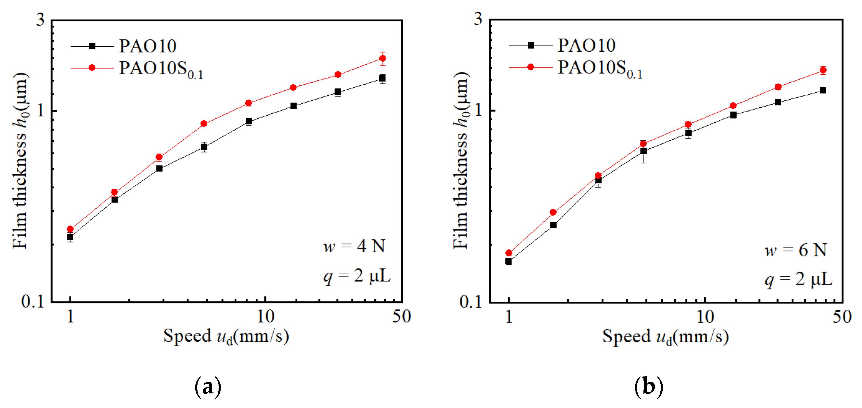
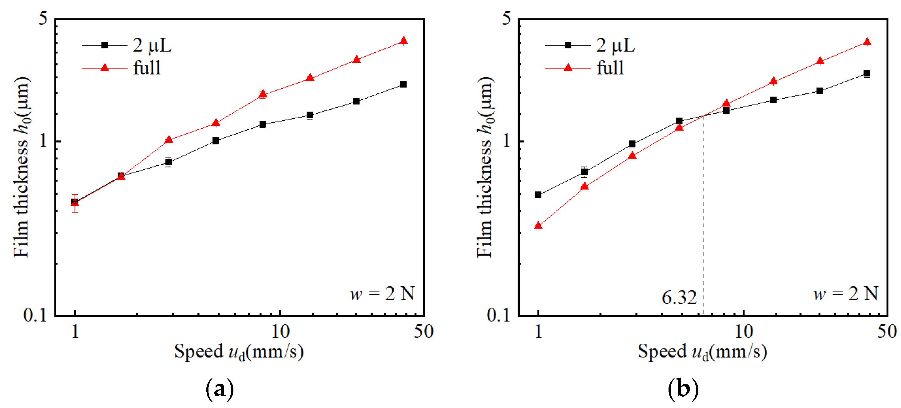
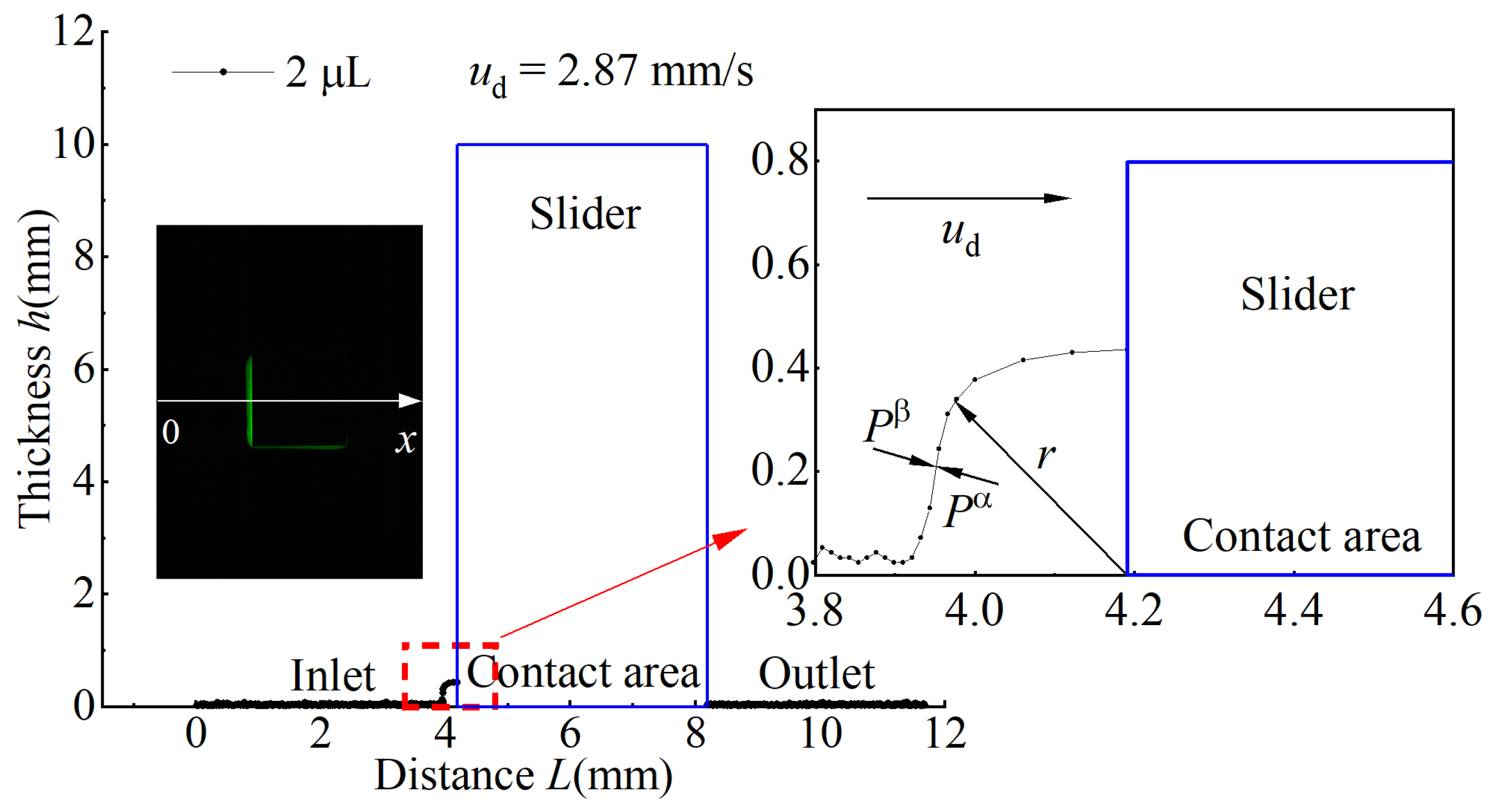
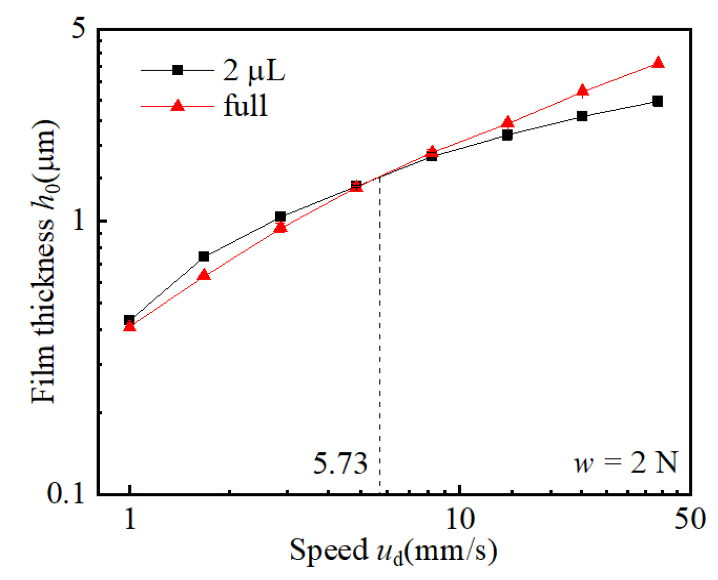
3.2. Effect of Stearic Acid Adsorption on Lubricating Oil Film
- is the pressure of the accumulated oil (Pa);
- is the ambient pressure (Pa);
- r is the radius of the curved surface (m).
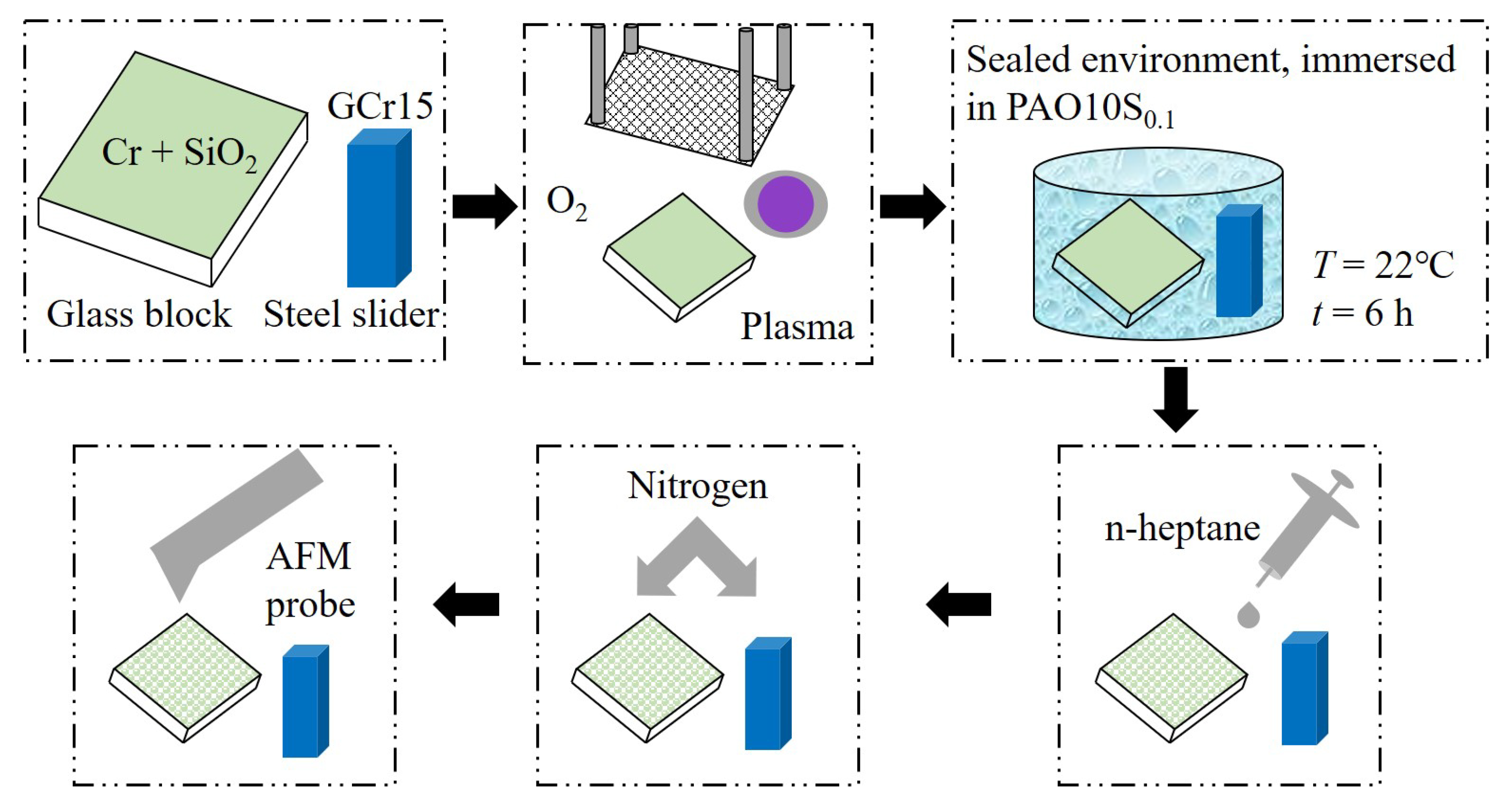
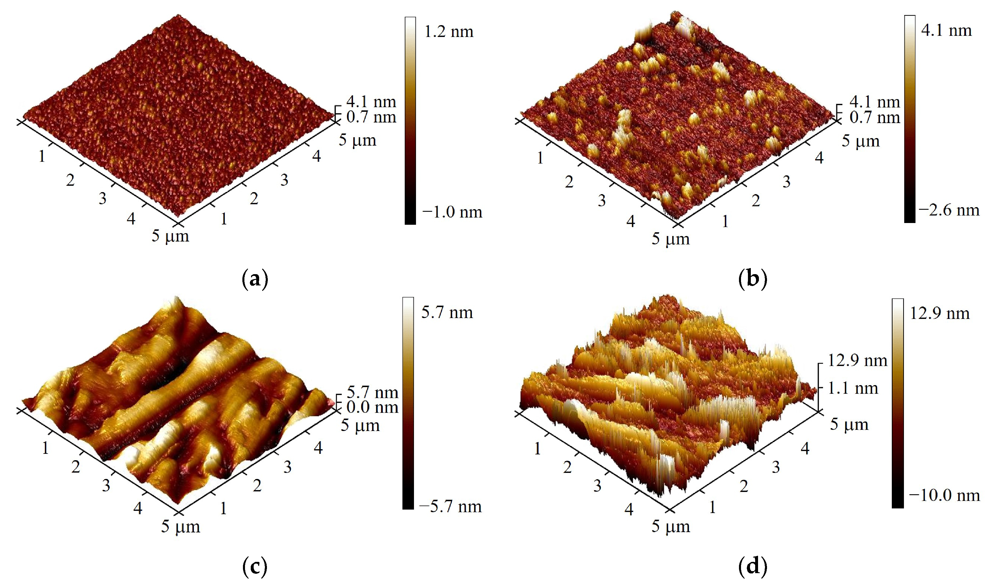
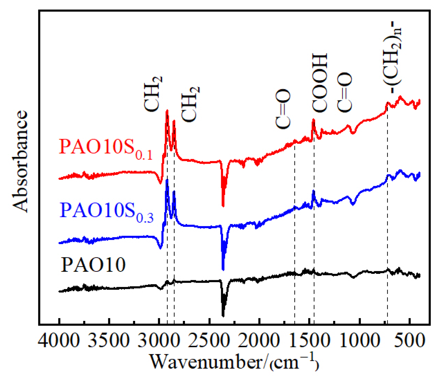
3.3. Surface Adsorption Characterization of Stearic Acid Additives
4. Conclusions
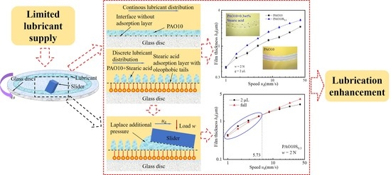
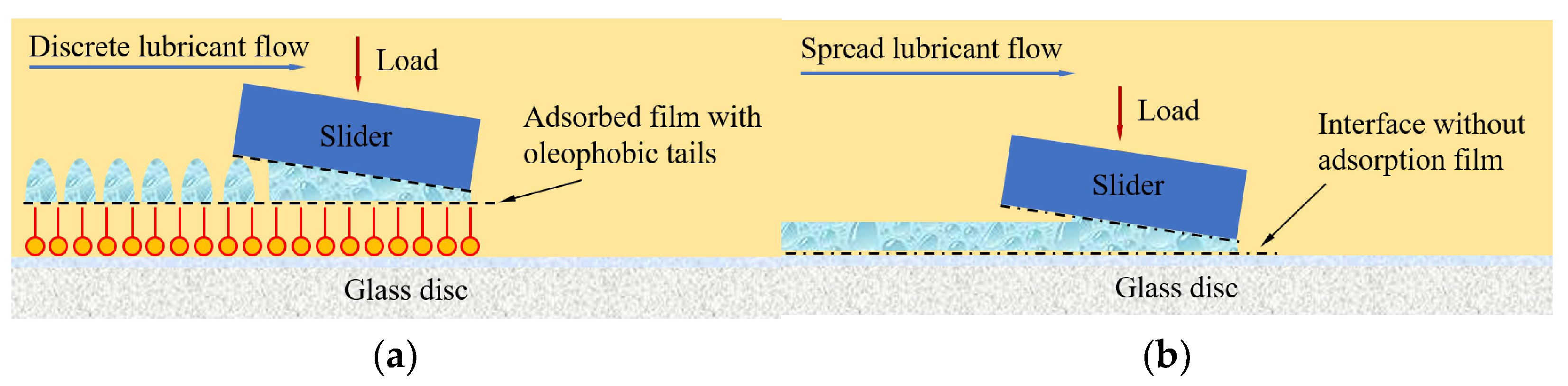
- Under LLS, with the addition of a small percentage of stearic acid to the base PAO oil, the lubricating oil presents a discrete stripe or droplet distribution owing to the stearic acid adsorption layer that changes the wettability of the surface.
- The discrete oil supply mode induced by stearic acid adsorption enriches the LLS lubrication, via the early contacts between the entrained oil and the slider surface.
- The accumulation of lubricating oil at the slider entrance caused by the discrete oil supply mode changes the pressure boundary condition at the bearing inlet, which plays a positive role in promoting the film formation capability.
- LLS lubrication can be improved by the adsorption of stearic acid, via the dewetting phenomenon. This new mechanism is worth further exploration to identify appropriate additives for the enhancement of LLS lubrication.
Author Contributions
Funding
Data Availability Statement
Conflicts of Interest
References
- Holmberg, K.; Erdemir, A. Influence of tribology on global energy consumption, costs and emissions. Friction 2017, 5, 263–284. [Google Scholar] [CrossRef]
- Wedeven, L.D.; Evans, D.; Cameron, A. Optical analysis of ball bearing starvation. J. Lubr. Technol. 1971, 93, 349–361. [Google Scholar] [CrossRef]
- Pemberton, J.; Cameron, A. A mechanism of fluid replenishment in elastohydrodynamic contacts. Wear 1976, 37, 185–190. [Google Scholar] [CrossRef]
- Kingsbury, E. Parched elastohydrodynamic lubrication. ASME J. Tribol. 1985, 107, 229–233. [Google Scholar] [CrossRef]
- Guangteng, G.; Spikes, H.A. The role of surface tension and disjoining pressure in starved and parched lubrication. Proc. IMechE. J. Eng. Tribol. 1996, 210, 113–124. [Google Scholar] [CrossRef]
- Cann, P.; Damiens, B.; Lubrecht, A.A. The transition between fully flooded and starved regimes in EHL. Tribol. Int. 2004, 37, 859–864. [Google Scholar] [CrossRef]
- Guo, F.; Zang, S.Y.; Li, C.; Wong, P.L.; Guo, L. Lubrication film generation in slider-on-disc contact under limited lubricant supply. Tribol. Int. 2018, 125, 200–208. [Google Scholar] [CrossRef]
- Chiu, Y.P. An analysis and prediction of lubricant film starvation in rolling contact systems. ASLE Trans. 1974, 17, 22–35. [Google Scholar] [CrossRef]
- Jacod, B.; Publier, F.; Cann, P.M.; Lubrecht, A.A. An analysis of track replenishment mechanisms in the starved regime. Tribol. Ser. 1999, 36, 483–492. [Google Scholar] [CrossRef]
- Liu, H.J.; Zhu, C.C.; Sun, Z.D. Starved lubrication of a spur gear pair. Tribol. Int. 2016, 94, 52–60. [Google Scholar] [CrossRef]
- Hamrock, B. Fundamentals of Fluid Film Lubrication; McGraw Hill: New York, NY, USA, 1994. [Google Scholar]
- Ali, F.; Krupka, I.; Hartl, M. Effects of out-of-contact lubricant channeling on friction and film thickness in starved elastohydrodynamic lubrication point contacts. Tribol. Int. 2013, 66, 134–142. [Google Scholar] [CrossRef]
- Ali, F.; Krupka, I.; Hartl, M. Mechanism for controlling oil replenishment in starved elliptical ehl contacts. Tribol. Lett. 2015, 60, 1–8. [Google Scholar] [CrossRef]
- Liu, C.L.; Guo, F.; Wong, P.L.; Li, X.M. Tribological behaviour of surfaces with stepped wettability under limited lubricant supply. Tribol. Int. 2020, 141, 105880. [Google Scholar] [CrossRef]
- Liu, C.L.; Guo, F.; Wong, P.L.; Li, X.M. Laser pattern-induced unidirectional lubricant flow for lubrication track replenishment. Friction 2022, 10, 1234–1244. [Google Scholar] [CrossRef]
- Guo, L.; Wong, P.L.; Gachot, C. Facilitating the study of the texturing effect on hydrodynamic lubrication. Lubricants 2018, 6, 18. [Google Scholar] [CrossRef]
- Shen, Z.; Wang, F.; Chen, Z.; Ruan, X.; Zeng, H.; Wang, J.; An, Y.; Fan, X. Numerical simulation of lubrication performance on chevron textured surface under hydrodynamic lubrication. Tribol. Int. 2021, 154, 106704. [Google Scholar] [CrossRef]
- Kalin, M.; Polajnar, M. The effect of wetting and surface energy on the friction and slip in oil-lubricated contacts. Tribol. Lett. 2013, 52, 185–194. [Google Scholar] [CrossRef]
- Polajnar, M.; Kalin, M. Effect of the slide-to-roll ratio and the contact kinematics on the elastohydrodynamic friction in diamond-like-carbon contacts with different wetting behaviours. Tribol. Lett. 2015, 60, 8. [Google Scholar] [CrossRef]
- Sun, B.W.; Chen, L.; Guo, L.; Wang, W.; Wong, P.L. Experimental evidence on the enhancement of bearing load capacity by localised boundary slip effect. Tribol. Lett. 2021, 69, 58. [Google Scholar] [CrossRef]
- Li, S.Y.; Guo, F.; Wong, P.L.; Li, X.M. Numerical analysis of lubrication of conformal contact with discontinuous oil droplets. Tribol. Int. 2022, 173, 107632. [Google Scholar] [CrossRef]
- Guo, L.; Wong, P.L.; Guo, F. Correlation of contact angle hysteresis and hydrodynamic lubrication. Tribol. Lett. 2015, 58, 45. [Google Scholar] [CrossRef]
- Guo, L.; Wong, P.; Guo, F. Identifying the optimal interfacial parameter correlated with hydrodynamic lubrication. Friction 2016, 4, 347–358. [Google Scholar] [CrossRef]
- Guo, F.; Wong, P.L.; Fu, Z.; Ma, C. Interferometry measurement of lubricating films in slider-on-disc contacts. Tribol. Lett. 2010, 39, 71–79. [Google Scholar] [CrossRef]
- Han, S.L.; Guo, F.; Shao, J.; Li, C. Velocity profile measurements of oil film under pure shear based on fluorescence photobleaching imaging method. Tribology 2017, 37, 442–448. [Google Scholar] [CrossRef]
- Wang, Q. Experimental Study of the Wettability of Conformal Contact Surfaces on Liquid Film Lubrication. Master’s Thesis, Qingdao University of Technology, Qingdao, China, 2018; pp. 49–54. [Google Scholar]
- Barnes, G.T.; Kingtel, I.R. Introduction to Interface Science, 2nd ed.; Science Press: Beijing, China, 2012; pp. 26–28. [Google Scholar]
- Yang, P.R. Numerical Analysis of Fluid Lubrication, 1st ed.; National Defense Industry Press: Beijing, China, 1998; pp. 20–26. [Google Scholar]
- Kalin, M.; Kus, M. New strategy for reducing the EHL friction in steel contacts using additive-formed oleophobic boundary films. Friction 2021, 9, 1346–1360. [Google Scholar] [CrossRef]


| Material | Molecular Formula | Molecular Weight | Density/(g/cm3) | Melting Point |
|---|---|---|---|---|
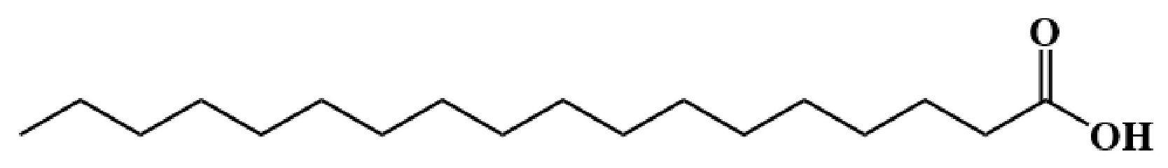
| Stearic acid | C18H36O2 | 248.48 | 0.847 | 67~70 |
| Coumarin-6 | C20H18N2O2S | 350.43 | 1.311 | 205–208 |
| Lubricant | Dynamic Viscosity η/(mPas@22 °C) | Refractive Index n |
|---|---|---|
| PAO10 | 120.1 | 1.4624 |
| PAO10S0.1 | 117.7 | 1.4625 |
| PAO10S0.3 | 119.9 | 1.4617 |
| PAO10+coumarin-6 | 116.3 | 1.4625 |
| PAO10S0.1+coumarin-6 | 119.2 | 1.4624 |
| PAO10S0.3+coumarin-6 | 117.1 | 1.4625 |
Publisher’s Note: MDPI stays neutral with regard to jurisdictional claims in published maps and institutional affiliations. |
© 2022 by the authors. Licensee MDPI, Basel, Switzerland. This article is an open access article distributed under the terms and conditions of the Creative Commons Attribution (CC BY) license (https://creativecommons.org/licenses/by/4.0/).
Share and Cite
Jian, Y.; Jing, Z.; Guo, F.; Wong, P.L.; Li, X. Experimental Study on the Lubrication Enhancement of Slider-on-Disc Contact by Stearic Acid Adsorption under Limited Lubricant Supply. Lubricants 2022, 10, 353. https://doi.org/10.3390/lubricants10120353
Jian Y, Jing Z, Guo F, Wong PL, Li X. Experimental Study on the Lubrication Enhancement of Slider-on-Disc Contact by Stearic Acid Adsorption under Limited Lubricant Supply. Lubricants. 2022; 10(12):353. https://doi.org/10.3390/lubricants10120353
Chicago/Turabian StyleJian, Yusheng, Zhaogang Jing, Feng Guo, Pat Lam Wong, and Xinming Li. 2022. "Experimental Study on the Lubrication Enhancement of Slider-on-Disc Contact by Stearic Acid Adsorption under Limited Lubricant Supply" Lubricants 10, no. 12: 353. https://doi.org/10.3390/lubricants10120353
APA StyleJian, Y., Jing, Z., Guo, F., Wong, P. L., & Li, X. (2022). Experimental Study on the Lubrication Enhancement of Slider-on-Disc Contact by Stearic Acid Adsorption under Limited Lubricant Supply. Lubricants, 10(12), 353. https://doi.org/10.3390/lubricants10120353