Abstract
Due to the demand for higher efficiency, gas engine designs are changing in that gas engine oils are exposed to higher thermal stress and face challenges regarding the prevention of deposits. In this work, the “oil chute” laboratory test was used to study the high-temperature deposit-formation tendency of various paraffinic and naphthenic base oil blends. The oil chute is a setup that circulates oil through two different temperature zones, the hot zone being a heated metal chute that triggers deposit formation. In addition, the thermo-oxidative stability of the oil blends was investigated using an artificial alteration method. The results showed that naphthenic base oils have the capability of substantially reducing high-temperature deposit formation. However, they tend to degrade faster under thermo-oxidative stress. Therefore, finding the right balance between paraffinic and naphthenic base oil components will allow the formulation of gas engine oils that provide the right properties to cope with the higher stress levels they are subjected to in modern gas engines.
1. Introduction
Modern gas engines are appealing due to their relatively high efficiency and lower CO2 emissions compared with liquid fuel engines [1,2,3]. The growing demand for electric power results in the need to further improve engine efficiencies by increasing the power density [4]. Thus, newer generations of gas engines feature an innovative design, e.g., including steel pistons, and operate at higher BMEP (Break Mean Effective Pressure) [5,6]. Due to the resulting higher operating temperatures, gas engine oils are subjected to higher stress, leading to increased deposit formation [7] and more intense thermo-oxidative degradation [6]. Both factors, among others, have undesirable consequences such as shorter oil-change intervals, more engine downtime, or even engine failure [5,6].
Although the formation of deposits is inevitable in gas engines operating under high temperature conditions, it needs to be minimised as much as possible. Engine oil is known to have a considerable influence on deposit formation [8], especially under high power density conditions [9]. As already reported in other contexts [10,11,12], the base oil of a lubricant plays an important role in additive expression and effectiveness, and should not be disregarded when attempting to optimise a lubricated system.
Hence, the following two aspects are important to consider when addressing the issue of deposit formation [7]:
- Developing new gas engine oil formulations: As the (thermal) stress levels for gas engine oils continue to rise [5], novel formulations need to be developed that meet the ever-increasing requirements. Both base oils and additives should be investigated in this context. In addition to the high-temperature deposit-formation tendency, the thermo-oxidative stability is one of the most important properties requiring consideration.
- Finding a test strategy: Given the high expenditure of money and time associated with engine [13] or field tests, the establishment of a suitable screening method is advisable. In this context, the implementability of realistic conditions, practical feasibility, and a good correlation of the results with field observations should be provided. Such a laboratory-based test method would enable the evaluation and comparison of various novel formulations before testing or application in the field.
This work focuses on the investigation of the deposit-formation tendency at high temperatures, testing various model blends regarding aspect I and addressing aspect II by introducing an in-house method called the “oil chute” test.
The examined model blends consisted of paraffinic base oils of API (American Petroleum Institute) Groups I to III and of mixtures of paraffinic and naphthenic (API Group V) base oils. A representative state-of-the-art performance additive package was added to all model blends to obtain lubricants that were comparable with fully formulated gas engine oils. The focus was on the effect that the base oil had on the lubricant performance, especially the naphthenic components. As a secondary aspect, the effect of reducing the proportion of a given additive package was also investigated. Besides the deposit-formation tendency, the thermo-oxidative stability of the model blends was evaluated using an artificial alteration method.
Naphthenic base oils provide more solvency to the formulation than do paraffinic base oils [14,15,16]. It is, therefore, assumed that the properties of a fully formulated gas engine oil can be tuned in the desired direction, towards improved system cleanliness and lower deposit formation by improving the solvency. Base oil solvency is related to aromatic content (and to viscosity) and can be expressed by the Aniline Point (ASTM D611 [17]). It is defined as the lowest temperature at which a mineral oil is completely miscible with an equal volume of aniline, a polar organic solvent. The lower the aniline point, the higher the solvency. The aromatic content of a base oil is controlled by the catalytic hydrogenation step during refining, where aromatic structures and parts of the complex oil molecules are converted to saturated naphthenic ring structures by the addition of hydrogen. Compared with a paraffinic base oil of the same viscosity, a naphthenic base oil will always have a higher solvency [15,16].
The oxidation stability of a base oil is related to its aromatic content and chemical nature. In general, more highly refined naphthenic base oils have low to very low (1500 ppm to 10 ppm) sulphur content and respond very well to added antioxidant additives. Earlier research [18] shows that, due to their relatively higher sulphur content, less harshly hydrotreated naphthenic base oils retain an ample supply of sulphur-containing molecules serving as natural antioxidants.
As for the application of naphthenic base oil in engine oils, not many examples can be found in the recently published literature. One such study was made on SAE (Society of Automotive Engineers) 40 type engine oils, where naphthenic base oils were part of the formulations [14]. In another publication, a reference to naphthenic base oils was included in a study on the heat-transfer properties of engine oils for internal combustion engines [19]. Thus, for some time, naphthenic base oils were largely left on the sidelines in terms of engine oil formulations. This research, therefore, aims to assess the high-temperature deposit formation of paraffinic and naphthenic oil blends, as this is an important parameter for internal combustion engine oils.
A laboratory test method used for the investigation of experimental model blends is described in this work. Previously applied methods investigating deposit formation often include tests with a specific apparatus that can only be acquired from selected suppliers, such as the panel coker [20], the TEOST (Thermo-Oxidation Engine Oil Simulation Test) MHT (Moderately High Temperature) [21], or the TEOST 33C [22]. An in-house method based on one of these well-established tests was published under the name of the “glass panel coker” [23]. Further methods such as the “Penn State micro-oxidation test” and the “Penn State micro autoclave test” were described by Kouame et al. [24,25]. Apart from these rather specific methods, several other standards exist that describe the determination of carbon residues, such as the Conradson carbon residue [26], the Ramsbottom carbon residue [27], and the Micro carbon residue [28].
As the available test methods were assessed to be either too unspecific, such as the carbon residue tests, or too particular, such as the TEOST MHT or TEOST 33C, an in-house method named the “oil chute” test was developed to meet the needs of the intended investigations. Temperature differences inspired by those occurring in a real gas engine were incorporated into the method and facilitated laboratory testing conditions close to reality. As a method validation strategy, a range of various commercially available reference gas engine oils was included in the study.
2. Materials and Methods
2.1. Samples
Paraffinic and naphthenic base oils from different API base oil groups were used for the preparation of experimental model blends. Table 1 lists the base oils and their respective API classification as well as their properties in fresh condition. Kinematic viscosities and viscosity indices were determined according to ASTM D7042 [29], aniline point according to ASTM D611 [17], and volatility according to ASTM D5800 (Procedure B) [30]. Sulphur and nitrogen contents were analysed according to ASTM D2622 [31] and ASTM D4629 [32], respectively.

Table 1.
Base oils used for model blends.
A comprehensive state-of-the-art performance additive package was added to all base oil blends to obtain fully formulated stationary gas engine oil compositions. Three different concentrations of the additive package were chosen considering the usual concentration ranges recommended by additive manufacturers. The typical recommended concentration is 10.5% and the recommended minimum concentration is 9.2%, with 7% representing a considerable deviation from manufacturer recommendations. Variations in the additive package concentration were aimed at investigating the effect of reducing the additive quantity on the overall performance without specifically addressing the individual additive groups. The combinations and concentrations of the base oil components (comp.), and the additive package, were chosen so that the kinematic viscosities of the model blends at 100 °C all lay within a similar range. Most of them precisely or approximately meet the requirements of an SAE 40 viscosity grade oil according to the SAE standard J300 [33]. The sole exception was MB-1, which was the only model blend containing one base oil.
The compositions of the final model blends and their respective kinematic viscosities at 100 °C can be seen in Table 2; this table also lists the aniline point of the respective base oil blends, i.e., the blends without the additive package. As the aniline point is usually determined in petroleum products without additives (as many types of additives would interfere with the aniline point determination), base oil blends without the addition of the additive package were subjected to the appropriate analysis [17].
Table 2.
Model blend compositions, respective kinematic viscosity at 100 °C, viscosity index and aniline point of base oil blends.
In order to include references, a variety of commercially available OEM (Original Equipment Manufacturer)-approved stationary gas engine oils was added to the test matrix. This approach allowed for a verification of the plausibility and the practicality of the oil chute method. Table 3 presents the reference oils and their respective field performance expectations. The stated performance expectations were based on field observations in conventional stationary gas engines with respect to the formation of high-temperature deposits. Indicators considered for the classification include oil drain intervals, cleanliness of engine parts, and thermo-oxidative behaviour. This subjective classification, pre-informative differentiation, and commentary were based on experience and the not-yet-proven hypothetical prognosis of a previously technically not-yet-specified, statistically not-yet-secured or well-defined estimation of the deposit-formation behaviour, and was made by Lubex Consulting e.U.
Table 3.
Reference gas engine oils.
2.2. Methods
2.2.1. Artificial Alteration
A thermo-oxidative artificial alteration method based on the standard CEC L-48-A00 [34] was carried out with selected model blends to achieve controlled accelerated degradation. This allowed for an assessment and comparison of the thermo-oxidative stability of the different model blends. Glass vessels (as specified in [34]) containing 100 mL of lubricant were immersed in a heating bath at 160 °C, while an air flow of 10 L/h was simultaneously applied to the lubricant through a glass tube. The total test duration for all alterations in this work was 192 h, as specified in the standard [34].
The artificially altered oil samples were subjected to various analyses such as acid and base number titrations, of which only the oxidation determined by FT-IR (Fourier Transform Infrared) spectroscopy according to DIN 51453 [35] is presented and discussed in this publication as this parameter is of high relevance for the evaluation of the thermo-oxidative stability. FT-IR spectra were recorded using an FT-IR spectrometer (Tensor 27, Bruker corporation, Billerica, MA, USA) in the range of 4000–500 cm−1. For the evaluation of the oxidation number, the software OPUS 5.0 (Bruker corporation, Billerica, MA, USA) was used. Nine of the twelve model blends listed in Table 2 were subjected to this artificial alteration.
2.2.2. Oil Chute
A newly developed method named the “oil chute” was used to assess the high-temperature deposit formation of the model blends and the reference oils. The concept of the oil chute is similar to that of the panel coker [20]. Its aim is to study the amount of deposit formed under continuous oil flow at a high temperature. The oil is circulated alternately through a hot and a “cold” zone, representing the oil movement in a stationary gas engine from hot zones near the pistons to cooler zones in the sump, and vice versa. A unique feature that distinguishes this method from the panel coker [20] is the temperature control of the sump that also allows active cooling. In contrast to other existing methods [21,22], real-life temperature differences can directly be incorporated into the oil chute method and the oil is cooled down to a specific temperature during each cycle before being pumped to the hot zone. The two actively and individually regulated temperature zones allow a customisation of the test to imitate various real-life systems and scenarios, whereas other methods [20,21,22] work with pre-set and restricted hot-zone temperatures and do not offer active cooling of the oil sump. Since it is a custom-built setup, a range of materials can be used in the hot zone, and there is no limitation on testing specimens available from specific manufacturers; this enables an even better adaptability to real-life systems.
The setup used in this study consists of a heated U-channel (10 × 20 × 10 × 2 mm) made of an aluminium alloy (AlMgSi0.5) that is inclined by 20°, the lower end of which is directly connected to a water-cooled reflux condenser made of glass. The end of the reflux condenser is connected to the upper end of the aluminium U-channel via an assembly of Rotilabo®-Viton®-tubes with an inner diameter of 4 mm (Carl Roth GmbH + Co. KG, Karlsruhe, Germany) involving a peristaltic pump. The lubricant to be examined is pumped continuously and with a defined flow rate over the hot U-channel and through the cooled reflux condenser for the duration of the test. The setup in use is shown in Figure 1.
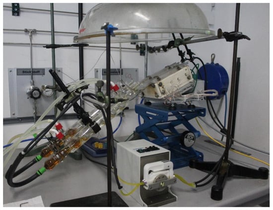
Figure 1.
Oil chute setup.
The detailed test parameters were as follows:
- U-channel temperature: 300 °C;
- Water cooling temperature: 40 °C;
- Sample amount: 85 g;
- Oil flow rate: ~7 mL/min;
- Test duration: 21 h.
The temperatures of the hot and cold zones were chosen following the real-life conditions in a stationary gas engine. Typical sump and hot-zone temperatures of gas engines with aluminium pistons are in the range of around 85 °C and 260–275 °C, respectively. Modern gas engines with steel pistons reach temperatures of approximately 95 °C in the sump and about 265–290 °C in the upper piston ring area [36]. To emphasise the temperature contrast and accelerate the process, the temperatures of the cold and hot zones were set at slightly more extreme values than those occurring in a real gas engine. The temperature in the sump (in the reflux condenser) was monitored throughout the test and observed to be around 45 °C.
An aluminium alloy was chosen as the material to come into contact with the oil in the hot zone because it is a material that is commonly used for gas engine pistons and offers the advantage of easy heat regulation due to its high thermal conductivity.
The test duration of 21 h allowed sufficient time for deposit formation and could easily be integrated into laboratory routine; this was so the test could be performed daily and allowed up to three hours of preparation time.
After completion of the test, the lubricant was carefully removed from the U-channel, the reflux condenser, and the silicone tubes by rinsing out any residual oil with n-heptane. The solvent was then removed by evaporation and the total lubricant weight was measured, thereby allowing the determination of the evaporation loss. Photo documentation of the deposits on the inner surface of the U-channel was recorded and the deposit amount was determined by differential weighing. It should be noted that a new U-channel was used for every test.
To obtain information about the oil condition, and similar to 2.2.1 above, the oxidation number was determined according to DIN 51453 [35]. Additionally, the kinematic viscosity was measured according to ASTM D7042 [29], using a Stabinger Viscometer (Anton Paar GmbH, Graz, Austria) to observe any change in viscosity compared with the lubricant in fresh condition.
All oil chute experiments were repeated, hence all results presented in this work which are related to them, i.e., deposit amount, evaporation loss, oxidation, and viscosity are arithmetic mean values calculated from two values; the respective standard deviations are indicated in the form of error bars in the plots.
3. Results and Discussion
3.1. Oxidation after Artificial Alteration and Oil Chute
Oxidation values for the model blends after the artificial alteration, as well as after the oil chute test, are displayed in Figure 2. These values were obtained from the respective FT-IR spectra by evaluating absorption bands that represent chemical compounds formed during oil oxidation processes containing a C=O group, such as ketones, aldehydes, carboxylic acids, and esters [37]. The more of these oxidation products present in the respective oil, the higher the oxidation number [35].
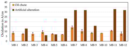
Figure 2.
Oxidation of model blends after oil chute test (orange) and after artificial alteration (brown).
After artificial alteration, the altered paraffinic model blends (MB-2, MB-4, and MB-5) had the lowest oxidation in comparison, producing oxidation numbers under or just above 10 A/cm (Absorbance/cm sample layer thickness). All investigated model blends consisting of both paraffinic and naphthenic base oils showed higher oxidation values, with only one (MB-9) lying under 20 A/cm. Moreover, with an increase of the fraction of naphthenic base oil, rising oxidation was observed. MB-7 and MB-8 contain the same base oils as MB-6, but their proportion of naphthenic oil was higher (see Table 2). The same applies to MB-11, MB-12, and MB-9, where MB-11 and MB-12 were the blends with a higher naphthenic oil content. Comparing the model blends in Figure 2, a substantially higher oxidation value can be noted for the four blends consisting of higher proportions of naphthenic oil. Reducing the amount of additive package in the model blends to 9.2 wt% does not seem to influence the oxidation behaviour as the affected blends (MB-8 and MB-12) showed almost identical oxidation values as the corresponding blends containing 10.5 wt% (MB-7 and MB-11).
Regarding oxidation after the oil chute test, all model blends lay in a rather low range of up to 15 A/cm. Again, the paraffinic model blends had lower oxidation values, below 10 A/cm, while the naphthenic blends exhibited slightly higher values.
Generally lower oxidation values and a less pronounced difference between the paraffinic and naphthenic oil blends can be observed after the oil chute test than after the artificial alteration. This can be attributed to the nature of the two methods. The focus of artificial alteration is oil deterioration by bulk oxidation [38], which is achieved by continuously bubbling air through the oil with the aid of increased temperature (160 °C). In contrast, the objective of the oil chute is to investigate the high-temperature deposit-formation tendency and to expose the oil to alternating moderate-temperature and brief high-temperature (300 °C) stress. Oxidation is an inevitable side effect occurring during the oil chute test, but it is not the emphasis of the method. Besides the mentioned differences, the duration of the two methods is not comparable as the oil chute test took 21 h and the artificial alteration 8 d. Temperature and duration of thermo-oxidative methods were also found to be influential on the oxidation processes by Diaby et al. [39].
The observations regarding oxidation after artificial alteration indicate a lower thermo-oxidative stability for oil blends containing naphthenic oils, which is not surprising given the higher aromatic content of naphthenic components in general. Aromatic content per se, but also the molecular speciation, influence oxidation stability, and the outcome of testing and antioxidant additive expression [12,14]. However, an acceptable oxidation value was obtained for one of the model blends (MB-9), demonstrating that with a careful base oil selection and an adjustment of the mixing ratio, a decent thermo-oxidative stability can be obtained.
3.2. Deposit Amount and Oil Characterisation after Oil Chute
Table 4 summarises the results of deposit amount, evaporation loss, viscosity change, and oxidation of all investigated reference oils and model blends after the oil chute test. As the deposit-formation tendency is discussed in detail in Section 3.2.1 and Section 3.2.2, Figure 3 visualises the remaining three characteristics. Evaporation loss lay between 10 and 35 wt% for all examined lubricants. Lower values were generally observed for the paraffinic model blends, while some of the blends containing naphthenic oil showed higher values, and reference oils demonstrated both. Viscosity change behaved similarly to evaporation loss, which is reasonable, as the evaporation of volatile components leads to a viscosity increase. Two of the reference oils (REF-2 and REF-5) were exceptions, as they reached a high viscosity increase despite moderate evaporation loss. Oxidation of the model blends was already discussed in Section 3.1. While the model blends showed consistently low values, the reference oils included both high and low oxidation numbers. The two reference oils that were distinctive in terms of their viscosity increase (REF-2 and REF-5) showed noticeably higher oxidation values. As oxidation processes are known to lead to sludge formation and viscosity increase, this connection seems reasonable and would explain the high viscosity increase despite the low evaporation behaviour.
Table 4.
Characteristics of all investigated oils after oil chute method.
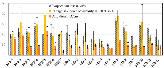
Figure 3.
Evaporation loss, viscosity change, and oxidation of tested lubricants after oil chute method.
3.2.1. High-Temperature Deposit of Reference Oils
A validation of the oil chute method was carried out using the reference gas engine oils listed in Table 3. Figure 4 shows the deposit amounts on the inner surface of the U-channel after the oil chute tests with the reference oils. Judging by the field performance expectations indicated in Table 3, the oil chute method was clearly able to distinguish between differently rated gas engine oils according to their high-temperature deposit-formation tendency. Reference oils rated “high” and “very high” (REF-4 and REF-7) show deposit amounts clearly below 50 mg, while those classified as “medium” and “good” (REF-1, REF-3, REF-5, and REF-6) lead to deposit amounts between 100 and 200 mg; the poorly rated oil achieves values over 300 mg of deposit.
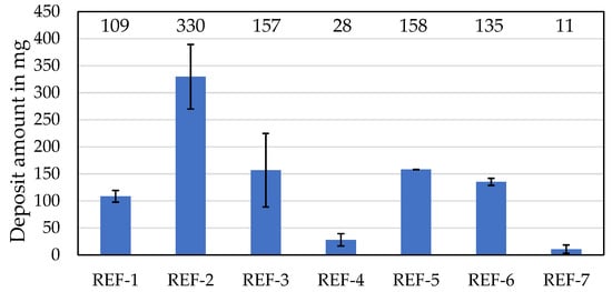
Figure 4.
Deposit amounts after oil chute tests with reference oils.
Overall, the results demonstrate the suitability of the oil chute method for assessing the high-temperature deposit formation of gas engine oils.
3.2.2. High-Temperature Deposit of Model Blends
Figure 5 presents the deposit amounts formed during the oil chute tests with the paraffinic oil blends. These showed comparable values and were all in the range of around 50–100 mg, matching the level of deposits formed by a reference oil rated “good”. Given these similar results, no significant differences between the different API group blends are demonstrated. Reducing the amount of additive package from 10.5 wt% in MB-2 to 7 wt% in MB-3 led to a slight increase in the average deposit amount, although even this difference is not significant considering the standard deviations.
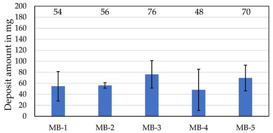
Figure 5.
Deposit amounts after oil chute tests with paraffinic oil blends (note: scaling of the y-axis was adjusted to smaller values).
The deposit amounts produced by the model blends with naphthenic components are shown in Figure 6. They lie in an even lower range, with most values remaining clearly below 50 mg and the highest value being around 70 mg. The model blends containing the naphthenic base oil N1 (MB-6–MB-8) all yielded very low deposit amounts, around 10–20 mg. For these blends, the formulation changes, i.e., an increase in the naphthenic content and a reduction in the additive package content, do not seem to have much effect on the deposit-formation tendency. Regarding the model blends containing N2 (MB-9–MB-12), an increase in the naphthenic fraction (MB-11) even led to a significantly lower deposit amount. Additionally decreasing the additive package to 9.2% (MB-12) had no noticeable effect, even with this blend. Thus, a moderate reduction within the recommendations of the additive package manufacturers (from 10.5 to 9.2%) does not appear to have a significant effect on the results. However, a significant reduction in the additive package to only 7% without increasing the naphthenic content (MB-10) led to elevated deposit formation. As was also observed with the paraffinic blends (MB-3) by trend, the use of too low an amount of additive package led to poorer results. It should be borne in mind that the highest value of the naphthenic model blends lies in the range of the paraffinic model blends and would still correspond to a “good” rating according to the reference oils. All other naphthenic blends were very competitive with the “high” and “very high” reference gas engine oils.
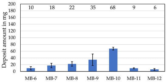
Figure 6.
Deposit amounts after oil chute tests with naphthenic oil blends (note: scaling of the y-axis was adjusted to smaller values).
Figure 7 depicts the appearances of selected U-channels with the deposits formed in the hot zone of the respective oil chute test. The upper three photos show the deposits of three differently rated reference oils. It can be seen that REF-2, with a “poor” rating, produced a high amount of dark brown to black deposits, while the “highly” rated REF-4 barely yielded deposits; REF-6, with a “good” rating, showed brown deposits that are in between the two previously mentioned oils in terms of amount. These observations are consistent with the quantitative values represented in Figure 4. The deposits resulting from two tests with paraffinic model blends are depicted in the two photos in the middle of Figure 7. Similar to the other paraffinic oils, MB-2 and MB-4 would be classified as “good” in terms of their high-temperature deposit-formation behaviour, which is reflected in the appearance of the respective U-channels after the test. A medium deposit amount of mostly brown colour can be observed for these samples. The bottom three photos in Figure 7 show the deposits formed by some of the naphthenic model blends. MB-10, which would correspond to a “good” rating in terms of its deposit amount and is therefore comparable with the reference oil REF-6 and the paraffinic blends MB-2 and MB-4, produced deposits of similar appearance as the mentioned oils. With less than 30 mg, MB-8 yielded a low quantity of deposits, very similar to the “highly” ranked REF-4. Appearance wise, the deposits of MB-8 extend over a slightly larger area and have a darker colour than those of REF-4, but they can be distinguished from those in the “medium” quantity range. Looking at the U-channel of the test with MB-12, which produced below 10 mg of deposits, the surface looks very clean compared with the others, and the deposits are of a much lighter brown colour and seem very thin.
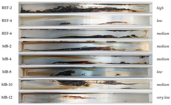
Figure 7.
Appearances of selected oil chutes after respective experiments. (Tested model blend given on the left and deposit amount classifications given on the right.)
In summary, it can be stated that the oil chute method enables a distinction of different model blends in terms of their high-temperature deposit-formation tendencies, and the appearances of the deposits agree with the respective quantitative results.
3.3. Formulation Considerations
The high-temperature deposit-formation tendency of paraffinic and naphthenic oil blends was already discussed in Section 3.2.1 and Section 3.2.2. The main finding was that the introduction of naphthenic oil to model blends resulted in a reduction of deposits. While the paraffinic oil blends all showed a similar and good performance regarding deposit formation, the naphthenic blends achieved even better results. In some cases, increasing the amount of naphthenic base oil led to a further decrease in deposit amount. Hence, from the point of view of deposit formation, the use of naphthenic base oils seems beneficial for the formulation of gas engine oils.
This observed behaviour of naphthenic oils is closely related to their high solvency performance. As the aniline point is representative of solvency properties, it was determined for the base oil blends without the additive package (see Table 2). Generally, the blends containing naphthenic base oils exhibit lower aniline points than those containing paraffinic oils only. Figure 8 shows the correlation between the aniline points of the base oil blends and the deposit amounts from the oil chute test for the respective final model blends. It can be seen that blends with a lower aniline point led to the formation of smaller amounts of deposits, while those with a higher aniline point produced larger deposit amounts. The fundamental correlation between higher solvency (lower aniline point) and fewer deposits is clearly displayed. The upper right part of the graph includes the five most paraffinic base oil blends which have higher aniline points, from 124 to 129 °C. These all have high deposit formation. The single outlier, at aniline point 119 °C and deposit about 70 mg, corresponds to the sample with the low (7 wt%) additive treat rate. It should be noted that the aniline point was not determined for the final model blends and the amount of additive package also influenced the deposit-formation tendency; this is why some of the deposits associated with the same aniline point shown in Figure 8 vary considerably. A lower aniline point indicates the enhanced ability of an oil to dissolve polar substances, thereby helping to prevent accumulation of insoluble components and subsequent deposit formation. Dissolvability of deposits and their precursors in oil was also observed to be an important factor in deposit-formation tendency by Yokoyama et al. [40].
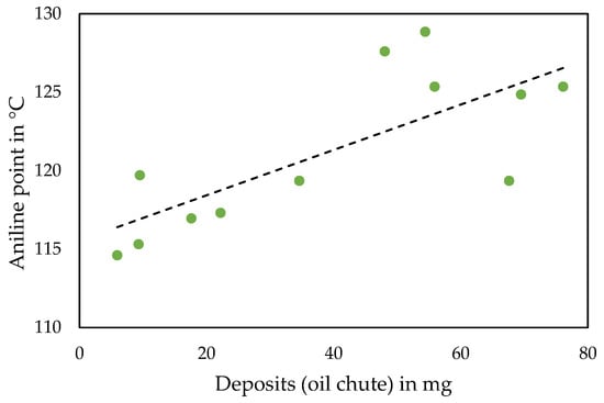
Figure 8.
Aniline point of base oil blends plotted against the respective deposit amount of model blends after oil chute experiment (a linear trend line is added for visualisation purposes).
When considering gas engine oil formulations, the deposit-formation tendency and solvency are not the only important factors. Other factors such as thermo-oxidative stability or acid neutralisation capability are essential for a balanced formulation. As part of this work, the thermo-oxidative stability was studied based on the artificial alteration described in Section 2.2.1 and discussed in Section 3.1. The relationship between oxidation after artificial alteration and the deposit amount after the oil chute method is illustrated in Figure 9. It can be noticed that model blends producing higher oxidation values during artificial alteration formed lower amounts of deposits during the oil chute test. As the dots representing low deposits and high oxidation belong to the naphthenic blends, this observation can be attributed to the presence of the naphthenic components, since they are said to have lower thermo-oxidative stability [14]. This would be expected based on the relative content of aromatic carbon types in the naphthenic oils compared with the highly refined and saturated Group II and III oils present in the paraffinic formulations. Given this circumstance, it is important to find a balanced mixture of naphthenic and paraffinic fractions to benefit from the desirable properties of both base oil types. MB-9 demonstrates the feasibility of this task, as this blend of naphthenic and paraffinic oils yields a lower deposit amount than the purely paraffinic blends (see Figure 5 and Figure 6), while showing low oxidation and low viscosity change after the oil chute test and a reasonable oxidation value after the thermo-oxidative alteration (see Figure 2 and Figure 3).
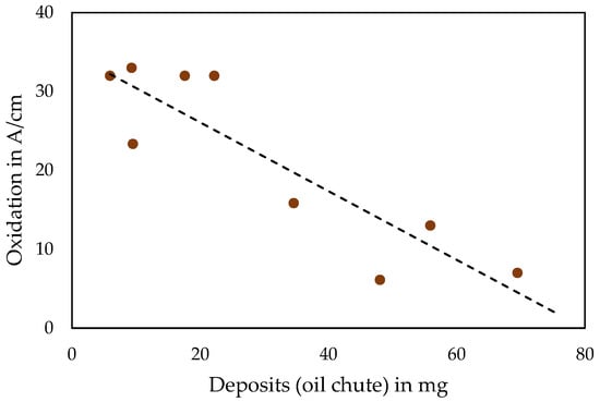
Figure 9.
Oxidation of model blends after artificial alteration plotted against the respective deposit amount after oil chute experiment (a linear trend line is added for visualisation purposes).
Regarding the aspect of additive package reduction, it was observed that when using naphthenic blends, the amount of additive package can be reduced to a certain extent (from 10.5 to 9.2%) without substantially changing the resulting behaviour in terms of deposit formation and thermo-oxidative stability. In the case of a significant reduction (to 7%), however, a negative influence on the engine oil performance was detected.
Formulating an optimal lubricant for a specific application is a challenging task, in which many aspects must be addressed, as was illustrated by Kagaya et al. [8] for the case of an engine oil for turbocharged engines. Clearly, there are many factors to consider regarding gas engine oil formulation, many of which were not treated in this work. Focusing on deposit-formation tendency, thermo-oxidative stability, and mainly on the role of the base oil, it is already clear that finding a balanced formulation that meets the various requirements is a complex task. However, it was shown that the right types and proportions of paraffinic and naphthenic base oils in combination with the right additive package concentration can achieve a blend with beneficial properties in terms of high-temperature deposit formation and thermo-oxidative stability.
4. Conclusions and Outlook
To fulfil the increasing performance requirements of gas engines, novel gas engine oil compositions are necessary. One of the most important aspects in this regard is an oil’s deposit-formation tendency at high-temperature conditions. The aim of this work was to investigate this characteristic using various experimental model blends of paraffinic and naphthenic base oils. In addition, the thermo-oxidative stability of the same model blends was studied and the relationship between the two examined properties was assessed. In this context, the opportunity of enhancing these properties using naphthenic components was explored.
An in-house laboratory test method, the oil chute test, was used to investigate the deposit-formation tendency of model blends consisting of paraffinic base oils of API Groups I to III and mixtures of paraffinic and naphthenic base oils. As the focus was mainly on examining the effect of the base oils, the same state-of-the-art performance additive package was added to all model blends. To include a benchmark, a range of commercially available reference gas engine oils was included in the study. The thermo-oxidative stability of the model blends was evaluated using an artificial alteration method.
The tests on the reference gas engine oils showed consistency with the field performance expectations and confirmed the applicability of the oil chute method for distinguishing their deposit-formation tendency. The oil chute method can thus be envisioned as a practical laboratory-based screening test that facilitates the testing and comparison of the deposit-formation behaviour of lubricants, as engine or field tests are usually expensive and time-consuming. It is proposed as a complement to existing methods, as it offers adaptability to individual real-life systems.
With regard to high-temperature deposit formation, the oil blends containing naphthenic components yielded very low levels and, thus, represent a significant improvement compared with purely paraffinic oil blends. Moreover, their deposit-formation tendency accords with that of highly rated reference gas engine oils, meaning that they offer an advantage over many conventional gas engine oils. Thus, adding selected naphthenic base oils to a formulation offers a direct route to gas engine oils with improved technical performance. It is also cost-effective in terms of addressing the cleanliness and deposit-formation issues via base oil selection compared with using higher additive pack treat rates or boosters.
By trend, the quantities of deposits formed during the oil chute test correlates with the aniline point of the respective base oil blend. A lower aniline point means higher solvency of polar substances and, hence, a better prevention of the accumulation of insoluble components and deposit formation. As naphthenic oils have lower aniline points, they introduce beneficial properties in this regard.
Concerning thermo-oxidative stability, purely paraffinic oils clearly outperformed blends that also contain naphthenic components. While this might not be an unexpected observation, thermo-oxidative artificial alteration also revealed noteworthy differences between diverse naphthenic blends. Generally, a difference could be noted between the two used naphthenic base oils and increasing the amount of naphthenic oil led to rising oxidation values.
Among all the requirements that new gas engine oil formulations are supposed to fulfil, both deposit-formation tendency and thermo-oxidative stability are important aspects to consider. Given the various benefits and drawbacks of paraffinic and naphthenic base oils, it is challenging to obtain a blend that meets all the expectations. However, it is concluded that with a suitable type and appropriate proportion of naphthenic and paraffinic components, the creation of a functional and balanced formulation is possible. Questioning current gas engine oil formulations creates space for the development of new strategies that can lead to more resilient lubricants and more reliable engine operation. This work contributes to understanding the effects of naphthenic base oil blends on the mentioned aspects and reveals savings potential for the quantities of additives used.
For future studies, the extension of the scope of investigation is proposed. While the work at hand focused on testing base oil behaviour, future work should also include the exploration of various additives and additive packages. In this context, the role of additives concerning the restriction or promotion of deposit formation is of particular interest. The current work shows the beneficial effect of naphthenic oils on the deposit-formation tendency, but it is not yet able to fully explain the background. Further studies scrutinizing whether the advantages result directly from superior base-oil solvency or from the additive operation being facilitated by this base oil environment are proposed. Investigations into the capability of additives to compensate for some unfavourable properties of base oils could also provide important insights. A higher goal could be the development of fully formulated gas engine oils together with an oil manufacturer and the demonstration of their performance in real gas engines.
Regarding the oil chute method, future work should include the elaboration of a statistically supported quantitative evaluation system based on a comprehensive data set. As further development, there are various possibilities for adapting the method to further questions and lubricants for other applications. One possible adjustment would be the use of a U-channel made of an iron alloy such as steel, as this is the material used for the pistons of new generation gas engines with high BMEP. By means of test parameter variation, the method can also be adapted to the operating conditions of other systems, e.g., turbines. Further work is proposed regarding an in-depth investigation of the chemical nature and structure of the deposits formed during the oil chute test, and a comparison with deposit samples from the field.
Author Contributions
Conceptualisation, C.S. and F.N.-F.; methodology, J.P. and C.S.; validation, J.P. and F.N.-F.; investigation, J.P. and C.S.; resources, T.N. and F.N.-F.; data curation, B.R. and C.S.; writing—original draft preparation, B.R. and J.L.; writing—review and editing, M.F., T.N., and C.S.; visualisation, B.R. and C.S.; supervision, M.F. and T.N.; project administration, C.S.; funding acquisition, C.S. and F.N-F. All authors have read and agreed to the published version of the manuscript.
Funding
This research was funded by the “Austrian COMET-Program” (project InTribology1, no. 872176) via the Austrian Research Promotion Agency (FFG) and the federal states of Niederösterreich and Vorarlberg.
Data Availability Statement
The data presented in this study are available on request from the corresponding author.
Conflicts of Interest
The authors declare no conflict of interest.
References
- Gharehghani, A.; Fakhari, A.H. Natural Gas as a Clean Fuel for Mobility. In Clean Fuels for Mobility; di Blasio, G., Agarwal, A.K., Belgiorno, G., Shukla, P.C., Eds.; Springer: Singapore, 2022; pp. 215–241. [Google Scholar]
- Divekar, P.; Han, X.; Zhang, X.; Zheng, M.; Tjong, J. Energy Efficiency Improvements and CO2 Emission Reduction by CNG Use in Medium- and Heavy-Duty Spark-Ignition Engines. Energy 2023, 263, 125769. [Google Scholar] [CrossRef]
- Li, F.; Wang, Z.; Wang, Y.; Wang, B. High-Efficiency and Clean Combustion Natural Gas Engines for Vehicles. Automot. Innov. 2019, 2, 284–304. [Google Scholar] [CrossRef]
- Lang, J.; Schäffert, P.; Böwing, R.; Rivellini, S.; Nota, F.; Klausner, J. Development of a New Generation of GE’s Jenbacher Type 6 Gas Engines. In Heavy-Duty-, On- und Off-Highway-Motoren 2016; Siebenpfeiffer, W., Ed.; Springer: Wiesbaden, Germany, 2016; ISBN 978-3-658-19011-8. [Google Scholar]
- Hughes, J. Development of a New Lubricating Oil for Use in Modern High Efficiency Gas Engines. In Proceedings of the CIMAC Congress, Vancouver, BC, Canada, 10–14 June 2019. [Google Scholar]
- Garcia, L.; Reher, J. Latest Generation of High Performance Gas Engine Oils—Tackling Reliability Challenges and Extending Oil Life in Modern Highly Efficient Gas Engines. In Proceedings of the CIMAC Congress, Vancouver, BC, Canada, 10–14 June 2019. [Google Scholar]
- Dowse, D.G.; Jansten, E.; Maier, K. Deposition in Gas Turbine Oil Systems—Part 1: Analysis and Classification; SAE Technical Paper 851869; Society of Automotive Engineers: Warrendale, PA, USA, 1985. [Google Scholar] [CrossRef]
- Kagaya, M.; Ishikawa, S. An Evaluation and Optimization of Lubricants for Turbocharged Gasoline Engines; SAE Technical Paper 840261; Society of Automotive Engineers: Warrendale, PA, USA, 1984. [Google Scholar] [CrossRef]
- Dong, L.; Liang, X.; Shu, G. The Influence of Lubricating Oil on Deposits Formation in a Diesel Engine under the Operation Condition of High Power Density. Lubr. Sci. 2013, 25, 441–451. [Google Scholar] [CrossRef]
- Castro, W.; Weller, D.E.; Cheenkachorn, K.; Perez, J.M. The Effect of Chemical Structure of Basefluids on Antiwear Effectiveness of Additives. Tribol. Int. 2005, 38, 321–326. [Google Scholar] [CrossRef]
- Saini, V.; Bijwe, J.; Seth, S.; Ramakumar, S.S.V. Role of Base Oils in Developing Extreme Pressure Lubricants by Exploring Nano-PTFE Particles. Tribol. Int. 2020, 143, 106071. [Google Scholar] [CrossRef]
- Barman, B.N. Behavioral Differences between Group I and Group II Base Oils during Thermo-Oxidative Degradation. Tribol. Int. 2002, 35, 15–26. [Google Scholar] [CrossRef]
- Lakatos, L.K.; Jones, R.N.; Roby, S.H.; Sukys, D.J. Modeling of ASTM Sequence IIIE Piston Ring Land Deposit Formation; SAE Technical Paper 922293; Society of Automotive Engineers: Warrendale, PA, USA, 1992. [Google Scholar] [CrossRef]
- Josefina, V.C.M.; Armando, I.R. Use of Naphthenic Base Stocks in Engine Oil Formulations; SAE Technical Paper 881585; Society of Automotive Engineers: Warrendale, PA, USA, 1988. [Google Scholar] [CrossRef]
- Torbacke, M.; Rudolphi, Å.K.; Kassfeldt, E. Lubricants: Introduction to Properties and Performance; Wiley: Chichester, UK, 2014; ISBN 9781118799741. [Google Scholar]
- Mortier, R.M.; Fox, M.F.; Orszulik, S.T. (Eds.) Chemistry and Technology of Lubricants; Springer: Dordrecht, The Netherlands, 2010; ISBN 978-1-4020-8661-8. [Google Scholar]
- ASTM D611; Standard Test Methods for Aniline Point and Mixed Aniline Point of Petroleum Products and Hydrocarbon Solvents. ASTM International: West Conshohocken, PA, USA, 2016.
- Norrby, T.; Jonsson, A.-L. Base Oil and Antioxidant Selection—The Role of Secondary Antioxidants and Base Oil Sulfur Content. In Proceedings of the 72nd STLE Annual Meeting, Atlanta, GA, USA, 21–25 May 2017. [Google Scholar]
- le Pera, M.E.; Oswald, G.E. Heat Transfer Characteristics of Lubricants for Internal-Combustion Engines. Ind. Eng. Chem. Prod. Res. Dev. 1974, 13, 209–213. [Google Scholar] [CrossRef]
- GFC-LU-29-A-15; Panel Coker Test. Groupement Français de Coordination pour le développement des essais de performance des Carburants, des Lubrifiants et autres fluides dans le Transport: Rueil-Malmaison, France, 2015.
- ASTM D7097; Standard Test Method for Determination of Moderately High Temperature Piston Deposits by Thermo-Oxidation Engine Oil Simulation Test—TEOST MHT. ASTM International: West Conshohocken, PA, USA, 2019.
- ASTM D6335; Standard Test Method for Determination of High Temperature Deposits by Thermo-Oxidation Engine Oil Simulation Test. ASTM International: West Conshohocken, PA, USA, 2019.
- Brown, G.; Barr, D.; Calder, R.; Durham, J.; McAtee, R.; Sutton, M. A New Screen Test for the Thermal Oxidative Stability of Engine Oils—The Glass Panel Coker; SAE Technical Paper 2004-01-2024; Society of Automotive Engineers: Warrendale, PA, USA, 2004. [Google Scholar] [CrossRef]
- Kouame, S.D.B. Application of Temperature-Programmed Oxidation (TPO) in Studying the Mechanism of Deposits Formation from the Degradation of Lubricants on Metal Surfaces. Lubr. Sci. 2014, 26, 117–130. [Google Scholar] [CrossRef]
- Kouame, S.D.; Liu, E. Characterization of Fully and Partially Additized Lubricant Deposits by Temperature Programmed Oxidation. Tribol. Int. 2014, 72, 58–64. [Google Scholar] [CrossRef]
- ASTM D189; Standard Test Method for Conradson Carbon Residue of Petroleum Products. ASTM International: West Conshohocken, PA, USA, 2006.
- ASTM D524; Standard Test Method for Ramsbottom Carbon Residue of Petroleum Products. ASTM International: West Conshohocken, PA, USA, 2015.
- DIN EN ISO 10370; Mineralölerzeugnisse—Bestimmung Des Koksrückstandes—Mikroverfahren. DIN (Deutsches Institut für Normung): Berlin, Germany, 2015.
- ASTM D7042; Standard Test Method for Dynamic Viscosity and Density of Liquids by Stabinger Viscometer (and the Calculation of Kinematic Viscosity). ASTM International: West Conshohocken, PA, USA, 2021.
- ASTM D5800; Standard Test Method for Evaporation Loss of Lubricating Oils by the Noack Method. ASTM International: West Conshohocken, PA, USA, 2021.
- ASTM D2622; Standard Test Method for Sulfur in Petroleum Products by Wavelength Dispersive X-Ray Fluorescence Spectrometry. ASTM International: West Conshohocken, PA, USA, 2021.
- ASTM D4629; Standard Test Method for Trace Nitrogen in Liquid Hydrocarbons by Syringe/Inlet Oxidative Combustion and Chemiluminescence Detection. ASTM International: West Conshohocken, PA, USA, 2017.
- SAE J300; Engine Oil Viscosity Classification. SAE International: Warrendale, PA, USA, 2015.
- CEC L-48-A00; Oxidation Stability of Lubricating Oils Used in Automotive Transmissions by Artificial Ageing. CEC (Co-ordinating European Council for the Development of Performance Tests for Fuels Lubricants and Other Fluids): Brussels, Belgium, 2007.
- DIN 51453; Prüfung von Schmierstoffen—Bestimmung Der Oxidation Und Nitration von Gebrauchten Motorenölen—Infrarotspektrometrisches Verfahren. DIN (Deutsches Institut für Normung): Berlin, Germany, 2004.
- Novotny-Farkas, F.; (Lubex Consulting e.U., Schwechat, Austria). Personal communication, 2021.
- Gracia, N.; Thomas, S.; Bazin, P.; Duponchel, L.; Thibault-Starzyk, F.; Lerasle, O. Combination of Mid-Infrared Spectroscopy and Chemometric Factorization Tools to Study the Oxidation of Lubricating Base Oils. Catal Today 2010, 155, 255–260. [Google Scholar] [CrossRef]
- Besser, C.; Agocs, A.; Ronai, B.; Ristic, A.; Repka, M.; Jankes, E.; McAleese, C.; Dörr, N. Generation of Engine Oils with Defined Degree of Degradation by Means of a Large Scale Artificial Alteration Method. Tribol. Int. 2019, 132, 39–49. [Google Scholar] [CrossRef]
- Diaby, M.; Sablier, M.; le Negrate, A.; el Fassi, M.; Bocquet, J. Understanding Carbonaceous Deposit Formation Resulting from Engine Oil Degradation. Carbon 2009, 47, 355–366. [Google Scholar] [CrossRef]
- Yokoyama, F.; Iwama, Y. Mechanism of Carbonaceous Deposit Formation Caused by Lubricating Oil on High Temperature Metal Surfaces. Tribol. Online 2014, 9, 71–79. [Google Scholar] [CrossRef][Green Version]
Publisher’s Note: MDPI stays neutral with regard to jurisdictional claims in published maps and institutional affiliations. |
© 2022 by the authors. Licensee MDPI, Basel, Switzerland. This article is an open access article distributed under the terms and conditions of the Creative Commons Attribution (CC BY) license (https://creativecommons.org/licenses/by/4.0/).