Abstract
Gas bearings have been widely applied to high-speed rotating machines due to their low friction and high rotational speed advantages. Nevertheless, gas lubrication is low viscosity and compressible. It causes the gas bearing-rotor system easy to produce self-excited vibration, which leads to instability of the rotor system and hinders the increase of rotor system speed. It is necessary to study the nonlinear behaviors of the aerostatic bearing-rotor system and the nonlinear vibration of the gas bearing-rotor system, especially considering the distribution mass and flexible and gyroscopic effects of the real rotor. In this paper, the nonlinear behavior of the gas bearing-rotor system is investigated from the viewpoint of nonlinear dynamics. Firstly, the dynamics model of a gas bearing rotor is established by combining the transient Reynolds equation and rotor dynamic equation obtained by finite element method (FEM). The transient Reynolds equation is solved using a hybrid method combining the differential transform method (DTM) and finite difference method (FDM). Then the transient gas force is substituted into the FEM rotor dynamic equation. In the end, based on the bifurcation diagram, the orbit of the rotor center, the frequency spectrum diagram and Poincaré map, the rotor system’s nonlinear behaviors are studied using a solution for the rotor dynamic equation with the Newmark method. Results show that there exists a limited cycle motion in the autonomous rotor system and half-speed whirl in the nonautonomous rotor system.
1. Introduction
With the merits of low noise, high precision, low friction, high rotational speed and long life, gas bearings have been widely applied in high-precision and high-speed rotating machines. Compared with traditional bearings, such as oil and ball bearings, gas bearings work with low heat generation, oil-free pollution and a simple auxiliary apparatus [1,2,3,4]. However, due to the compressibility and low viscosity of the gas, gas bearings tend to have nonlinear behavior, which limits their wide application [5,6]. Thus, it is necessary to investigate the nonlinear vibration performance of the gas bearing-rotor system under high-speed conditions.
In general, the finite difference method (FDM) or finite element method (FEM) is used to solve the transient Reynolds equation to obtain the nonlinear gas film force. Then, combined with the solution for motion equations of rotor, the nonlinear vibration performance of the gas bearing-rotor system are studied. Wang [7] studied the nonlinear behaviors of the rigid rotor supported by aerodynamic journal bearing and presented the 4T-periodic motion, but the investigations did not consider the unbalanced mass force. Zhang [8] used FEM to solve the transient Reynolds equation to obtain the gas film force. Then the trajectory of the journal, Poincaré maps, power spectra and bifurcation diagrams were used to investigate the nonlinear behavior of the gas bearing-rigid rotor system. The results showed that there exists limited cycle motion in the autonomous rotor system, and half-speed whirl and quasi-periodic motions in the nonautonomous system. In Refs. [7,9], the rotor is assumed as the lumped mass model, and the rotor should be treated as the distribution mass. Rashidi studied the influences of rotor mass, bearing number [10] and preload [11] on the nonlinear performances of the lobe aerodynamic journal bearing-rigid rotor system. Lu [12] investigated the nonlinear dynamic behaviors of the fixed-tilting-pad self-acting gas bearing-rigid rotor system by using the hybrid method of DTM and FDM. Moreover, the influences of pivot ratio and the preload coefficient on the nonlinear dynamic behavior of the rotor system were studied. The results showed that the preload coefficient can improve the stability of the gas bearing-rotor system while the pivot ratio affects the nonlinear dynamic behaviors significantly. Li [13] studied the effects of the directions, amplitudes and the numbers of surface waviness on the nonlinear characteristics of the gas bearing-rotor system. The results showed that circumferential direction waviness can improve the system’s stability, but axial direction waviness leads to damage to the system. Moreover, the nonlinear performance of the rotor system is not sensitive to the frequency of the waviness, and increasing the amplitude of the circumferential direction waviness can also improve the stability. Larsen [14] also studied the sub-synchronous vibration of the gas foil bearing-rotor system from the turbo compressor. However, this research focuses on rotational speed and the degree of unbalance. The above work involving the nonlinear behaviors of the gas bearings all study hydrodynamic gas bearings. Belforte [15] modified the transient Reynolds equation of the aerostatic bearing to consider the inertial effect of the gas, and results show that the inertial effect can be ignored when the modified Reynolds number is larger than 1. Dal [16] also utilized the hybrid method and studied the pneumatic hammer. The vibration amplitude of the rotor system with nonlinear behaviors can be large enough, resulting in the rubbing of the bearing and rotor. Some research was done to study the measures to control nonlinear vibration. Kumar [17] studied the limit cycle behavior, and then investigated the effects of compressibility and bearing stability parameters on bifurcating limit cycles. From this, the safe operating range diagrams of the rotor system were obtained. As the gas film thickness is too small, the gas rarefaction effect should be considered in studies on the performances of the rotor system supported by micro-bearings. Considering the effect of the temperature on the rarefaction effect, Gharanjik [18] studied the influence of the temperature on the nonlinear behavior of the non-circular micro gas bearing-rotor system using the molecular gas lubrication (MGL) model. The results show that high temperature would result in nonlinear vibration from the linear vibration. Liu studied the nonlinear behavior of a rigid rotor supported by herringbone grooved journal gas bearings (HGJBs) The results showed that the static load can improve HGJB stability. In the past two decades, based on the rotor trajectory, phase maps, Poincaré maps, power spectrum maps and bifurcation diagrams, Wang investigated the effects of the rotor mass, rotate speed and unbalanced mass on the nonlinear vibration of gas bearings, such as the aerodynamic journal bearing [7], aerostatic bearings [19,20], spherical aerodynamic bearing [21] and so on.
As shown in Refs. [8,9,10,11,12,13,14,15,16,17,18,19,20,21], the rotor in the gas bearing-rotor system is assumed a rigid and lumped mass rotor. This model neglects the rotor elasticity and distributed mass. Moreover, as the gas bearing is used in high-speed machines, the gyroscopic effect must be considered. Therefore, the rotor dynamic equation should be established using the beam element, which considers the gyroscopic effect. In the present paper, combined with the nonlinear gas film force obtained by the solution for the transient Reynolds equation with a hybrid method, the dynamic equation of a gas bearing-rotor system was solved using the Newmark method to investigate the nonlinear characteristics of the rotor system.
2. Mathematical Model
2.1. Solution for Transient Reynolds Equation with Hybrid Method
The schematic diagram of aerodynamic bearing conditions is shown in Figure 1. X direction, Y direction, Z direction and are horizontal, vertical, axial and circumferential directions, respectively. Zm plane is the mid-plane of the gas bearing along the axial direction, while the and is the attitude angle and eccentricity in the mid plane Zm. The film thickness can be expressed as Equation (1). Then, the Reynolds equation is adopted to research the characteristics of aerodynamic bearings and the corresponding Reynolds equation is shown as Equation (2)
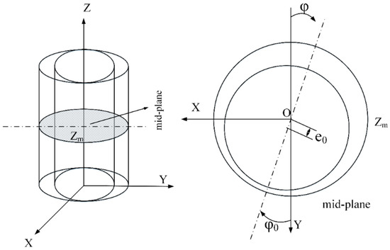
Figure 1.
The schematic view of an aerodynamic bearing.
The dimensionless parameters are shown next:
where is the radial bearing clearance, is eccentricity, is the attitude angle in the mid plane, is atmosphere pressure, is the bearing radius, is the bearing length, is the gas dynamic viscosity, is the rotational speed, is bearing number, and are the dimensional and dimensionless pressures, and are the dimensional and dimensionless film thicknesses, and are the dimensional and dimensionless times. By using the DTM, Equation (2) can be changed as:
where
Then, by substituting Equation (4) into Equation (3) and the central finite difference method, we can get the discrete algebraic equations
As shown in Figure 2, there exists two boundaries:
- (1)
- coincidence boundary is ;
- (2)
- atmosphere boundary is .
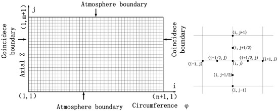
Figure 2.
Computational domain of Reynolds equation and grid structure.
As shown in Ref. [22], in order to accelerate the rate of convergence and improve the accuracy of the calculations, the overall t domain is split into a number of sub-domains and DTM is then used to solve the differential equation in each domain. Moreover, similar to Ref. [12], the k is equal to 1 in each sub-domain. Then, in each sub-domain, by solving Equation (5), the next time step, transient pressure of the gas film is obtained by Equation (6), and then the transient gas film forced along X and Y directions can be computed by the Equation (7). In addition, the H(0), H(1), H(2) in the process of the solution of the hybrid method are obtained by Equation (8).
2.2. The Dynamic Equation of Aerodynamic Bearing-Rotor System
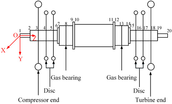
Figure 3 is the schematic view of the gas bearing-rotor system with multiple disks, including a multi-diameter shaft, compressor and turbine end, four discs and two aerodynamic bearings. The rotor system can be divided into 19 beam elements and have 20 nodes, where rotor is assumed as Timoshenko beam (see Appendix A) elements and the disks, compressor and turbine are assumed as lumped mass elements. The dynamic equation of the bearing-rotor system can be expressed as Equation (9)
 where is mass matrix, is damping matrix, is gyroscopic matrix, is the stiffness matrix, is external forces including unbalanced mass force and gas film force and is the displacement, velocity and accelerated matrix, respectively. Rayleigh damping was considered in this paper, i.e., only contains Rayleigh damping. The system is autonomous when includes only the gas film force, while the system is nonautonomous when includes unbalanced mass and gas film forces. The solution for the dynamic equations of the gas bearing-rotor system is an iterative procedure combining the Newmark method with the hybrid method, as shown in Figure 4. The iterative procedure is described as follows:
Figure 3.
The schematic view of gas bearing-rotor system with multiple discs.
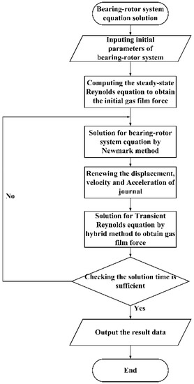
Figure 4.
The flow chart of the solution for bearing-rotor system equation.
- (1)
- The initial steady equilibrium state is calculated using the steady Reynolds equation, and then the inertial displacement is determined, while the inertial velocity is assumed to be zero;
- (2)
- The displacement, velocity and accelerated matrix are obtained by solution for Equation (9) using the Newmark method;
- (3)
- Renew the displacement, velocity and acceleration of the journal;
- (4)
- The transient gas film force is obtained by solving the transient Reynolds equation with the hybrid method;
- (5)
- Renew the external force matrix and go back to step 2, then the displacement, velocity and accelerated matrix of the next time step is determined using the Newmark method;
- (6)
- The computing process step 2 to step 5 is repeated until the computing time is complete.
In this paper, the time step of the calculation is π/5000 and the total time in the process is 1500 periods; the time series data of the first 1000 periods are excluded from the nonlinear behavior investigation to ensure that the analyzed data meets the steady-state conditions. The gas bearing-rotor system parameters are shown in Table 1.

Table 1.
The parameters of aerostatic bearing-rotor system.
3. Results and Discussion
3.1. The Verification of the Hybrid Method
In order to prove the validity of the hybrid method, the results obtained by the hybrid method are compared with the results from references published and computed using traditional FDM.
Case 1:
The calculation parameters are , , and or 0.15. The root locus obtained using the hybrid method is compared with the results of Ref. [15]. The hybrid method is used to solve the transient Reynolds equation and the other calculation conditions are the same as Ref. [15]. As shown in Figure 5, the root locus obtained using the hybrid method is in good agreement with the results from Ref. [15], which means that the program of the hybrid method in this paper is right. Moreover, the results show that the rotor system without unbalanced mass will approximate to a point, namely, stable focus, after transient time, shown the left of Figure 5 when the . On the other hand, with the increasing rotor mass , the behavior of the rotor system will keep a stable focus, i.e., closed cycle. From the trajectory portrait, it can be seen that there exists a limit cycle.
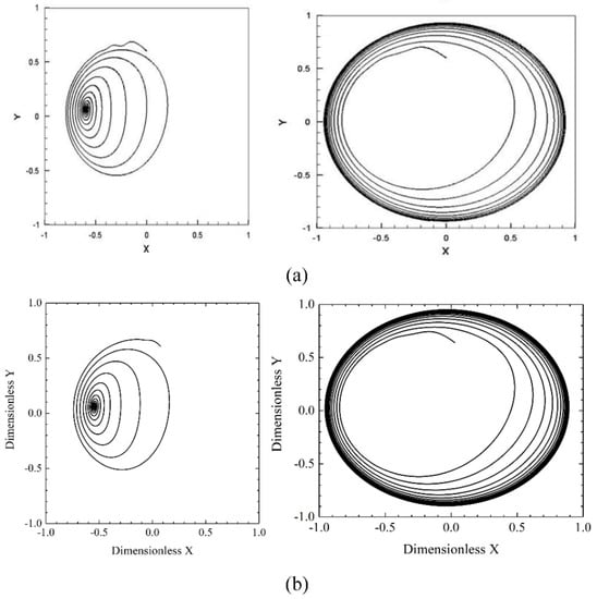
Figure 5.
The comparison with the results from Ref. [23]. (a) results from the reference [23]; (b) results from this paper.
Case 2:
The calculation parameters are , , , the unbalanced mass , , time step , while the rotor parameters are shown in Table 1. In this case, the simulation time is 40 periods which is 0.2 million steps. The time history along different directions and orbit of the shaft center obtained by the hybrid are compared with the results obtained by the traditional FDM, which is shown in Figure 6. The results showed that the simulation results from the hybrid and traditional FDM are almost the same. However, the consumption time of the hybrid method is reduced by almost 38% compared with traditional FDM, which means that the hybrid method is more efficient. In addition, the trajectory portrait grows with simulation time, and finally forms a limit cycle. The center of the limit cycle is not zero caused by gravity.
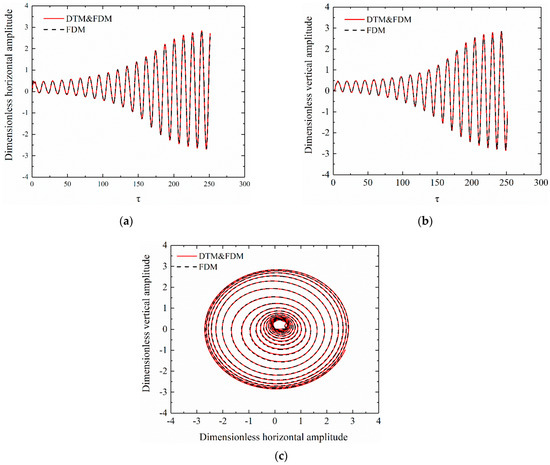
Figure 6.
The comparison with the results from the traditional FDM. (a) time history of rotor system along X direction, (b) time history of rotor system along Y direction, (c) the orbit of the rotor center.
3.2. The Nonlinear Vibration of Autonomous System
The rotor system is autonomous when the external force only includes gas film force. The nonlinear characteristics of the autonomous rotor system were studied with the calculation parameters of case 2.
As shown in Figure 7, the bifurcation diagrams of displacement along X and Y directions are given without unbalanced mass. According to Figure 7, when the rotational speed is less than 8000 rpm, the rotor motion will approximate to a stable balance point, and the gravity is equal to the gas film force. The typical characteristics, including trajectory and time history at 6000 rpm are shown in Figure 8. As shown in Figure 8, the trajectory of the rotor system decreases with the simulation time. It approximates to a point, namely, stable focus, after transient time.
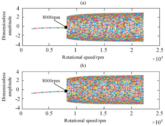
Figure 7.
The bifurcation diagrams of displacement along different directions without unbalanced mass (a) along X direction; (b) along Y direction.
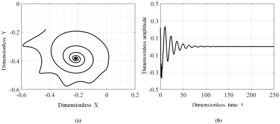
Figure 8.
The trajectory and time history of the rotor system at 6000 rpm without unbalanced mass: (a) trajectory, (b) time history.
When the rotor speed is more than 8000 rpm, the behavior of the rotor system is in the bifurcation state, and the rotor motion will tend to limit cycles. The typical characteristics including trajectory, time history and frequency spectrum at 12,000 rpm are shown in Figure 9. As shown in Figure 9, after a short time, the locus is a closed cycle and the temporal waveform presents a sine wave state. Moreover, there exists 0.5× less rotational frequency in the frequency spectrum, which is the half-speed whirl. This is the nonlinear vibrations caused by the nonlinear force of the gas bearing. This means that the behavior of rotor system without unbalanced mass will be changed with increasing rotational speed.
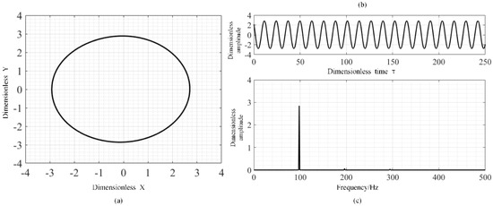
Figure 9.
The trajectory, time history and frequency spectrum of the rotor system at 12,000 rpm without unbalanced mass: (a) trajectory, (b) time history, (c) frequency spectrogram.
3.3. The Nonlinear Vibration of Nonautonomous System
When the external forces include gas film force and unbalanced mass force, the rotor system is nonautonomous system. The nonlinear characteristics of the autonomous rotor system were studied with the calculation parameters of case 2.
As shown in Figure 10, the bifurcation diagrams of displacement along X and Y directions are given with unbalanced mass. According to Figure 10, with increasing rotational speed, the different nonlinear behavior of the rotor system is presented at different rotational speed. When the rotational speed is less than 7800 rpm, the rotor system is in 1T-period motion. With increasing rotational speed, the 1T-period motion of gas rotor system is changed as 2T-period motion at rotational speed range of 7800 rpm to 19,400 rpm. The motion state of the system is changed as 1T-period motion under speed greater 19,600 rpm. The typical characteristics of 1T-period motion including trajectory, time history and frequency spectrum at 6000 rpm, are shown in Figure 11. As shown in Figure 11 and Figure 12, the gas rotor system is under 1T-period motion, and the orbit presents as an ellipse, while there exists only one point in the Poincaré map and the spectrum diagram contains only rotating frequency caused by the unbalanced mass force. Under the 1T-period motion, the dynamic performance of the gas bearing-rotor system is under a linear vibration state.
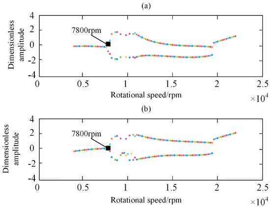
Figure 10.
The bifurcation diagrams of displacement along different directions with unbalanced mass (a) along X direction; (b) along Y direction.
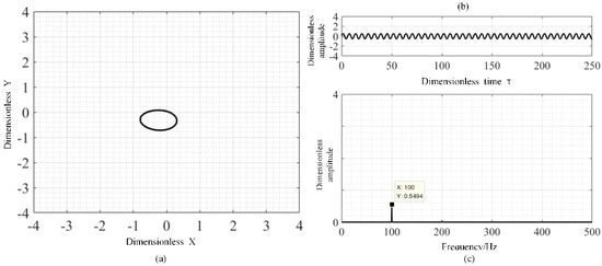
Figure 11.
The trajectory, time history and frequency spectrum of the rotor system at 6000 rpm with unbalanced mass: (a) trajectory, (b) time history, (c) frequency spectrogram.
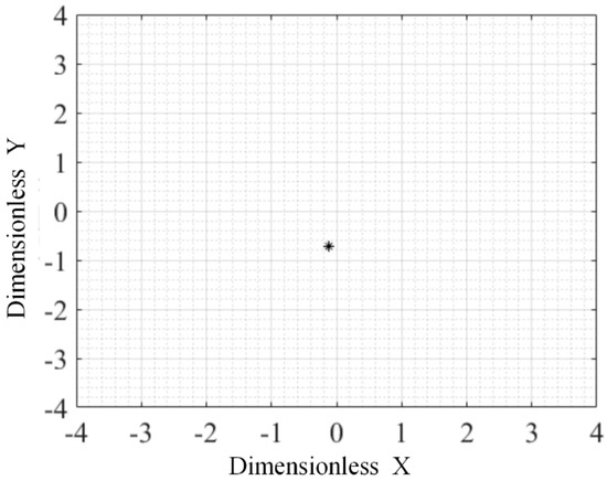
Figure 12.
The Poincaré section of the rotor system at 6000 rpm with unbalanced mass.
When the rotor speed is more than 7800 rpm, the behavior of the rotor system is in the bifurcation state and the rotor motion will tend to 2T-period motion, during which the system motion is under half-speed whirl. The typical characteristics of 2T-period motion including trajectory, time history and frequency spectrum at 12,000 rpm are shown in Figure 13. As shown in Figure 13, the orbit of 2T-period motion is not an ellipse and changes into an “8” shape, while there exists 0.5× rotational frequency in the frequency spectrum. Correspondingly, there exists two points in the Poincaré map as shown in Figure 14. Under the 2T-period motion, the dynamic performance of the gas bearing-rotor system is under a nonlinear vibration state caused by the nonlinear gas force. The nonlinear gas force results in the existence of two frequencies, i.e., 0.5× and 1× rotational frequency, in the spectrum plot shown in the bottom right corner of Figure 14.
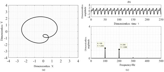
Figure 13.
The trajectory, time history and frequency spectrum of the rotor system at 12,000 rpm with unbalanced mass: (a) trajectory, (b) time history, (c) frequency spectrogram.
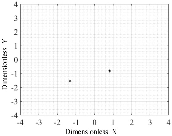
Figure 14.
The Poincaré section of the rotor system at 12,000 rpm with unbalanced mass.
4. Conclusions
In this paper, the nonlinear performances of aerodynamic bearing-rotor system are investigated using the combined hybrid method and FEM. Based on the bifurcation diagrams, trajectory and Poincaré section of the rotor, the nonlinear characteristics of the autonomous and nonautonomous rotor system are presented and the main conclusions are given as follows:
- (1)
- By comparing our results with the results from reference papers and traditional FDM solutions, the higher efficiency of the hybrid method is proven and correctness of the method is also verified.
- (2)
- When the rotational speed of an autonomous rotor system is less 8000 rpm, the behavior of the system is in the stable point state. The behavior of the rotor system is in the bifurcation state. The rotor motion will tend to limit cycles when the speed is more than 8000 rpm.
- (3)
- With increasing the speed of the nonautonomous rotor system, the behavior of the system is changed from 1T-period motion to 2T-period motion.
Author Contributions
Conceptualization, J.Z.; methodology, K.Z. and X.H.; formal analysis, K.Z., Z.D., D.W., M.S. and Y.C.; investigation, Z.X., D.W. and X.H.; writing—original draft preparation, J.Z.; writing—review and editing, J.S.; funding acquisition, Z.S. and M.S. All authors have read and agreed to the published version of the manuscript.
Funding
The present research has been funded by National Science and Technology Major Project of China (J2019-IV-0005-0072 and 2017-I-0008-0009); the authors would like to sincerely express their appreciation.
Data Availability Statement
The datasets used and/or analyzed during the current study are available from the corresponding author upon reasonable request.
Conflicts of Interest
The authors declare no conflict of interest.
Appendix A
In the manuscript, the rotor is described by Timoshenko beam elements and its element mass matrix is shown as:
The and are shown as follows:
And the coefficients of and are obtained by:
where is the shear constant, is the Young’s modulus, is Poisson’s ratio, is the ratio of the inner shaft radius to outer shaft radius, is the shear modulus, is the second moment of area of the cross section about the neutral plane, is length of the element and the subscript e represents element. Its element stiffness matrix and gyroscopic matrix are shown as:
where
Moreover, the mass matrix and gyroscopic matrix of the disk element are shown as follows:
where, is the mass of disk, is the diametral moment of inertia of the disk and is the polar moment of inertia of the disk.
In the end, by assembling the mass, stiffness and the gyroscopic matrix of beam and disk elements, the general form of the equation for an degree of freedom system considering the Rayleigh damping becomes the Equation (9) in Section 2.2.
References
- Zhang, J.; Zou, D.; Ta, N.; Rao, Z. Numerical research of pressure depression in aerostatic thrust bearing with inherent orifice. Tribol. Int. 2018, 123, 385–396. [Google Scholar] [CrossRef]
- Zhang, J.; Zou, D.; Ta, N.; Rao, Z.; Ding, B. A numerical method for solution of the discharge coefficients in externally pressurized gas bearings with inherent orifice restrictors. Tribol. Int. 2018, 125, 156–168. [Google Scholar] [CrossRef]
- Dal, A.; Karaçay, T. Effects of angular misalignment on the performance of rotor-bearing systems supported by externally pressurized air bearing. Tribol. Int. 2017, 111, 276–288. [Google Scholar] [CrossRef]
- Zhu, X.; San Andrés, L. Rotordynamic Performance of Flexure Pivot Hydrostatic Gas Bearings for Oil-Free Turbomachinery. J. Eng. Gas Turbines Power 2007, 129, 1020–1027. [Google Scholar] [CrossRef]
- Wang, C.C.; Yau, H.T. Theoretical analysis of high speed spindle air bearings by a hybrid numerical method. Appl. Math. Comput. 2010, 217, 2084–2096. [Google Scholar] [CrossRef]
- Han, D.; Tang, C.; Hao, L.; Yang, J. Experimental studies on the effects of bearing supply gas pressure on the response of a permanent magnet disk-type motor rotor. J. Mech. Sci. Technol. 2016, 30, 4887–4892. [Google Scholar] [CrossRef]
- Wang, C.C.; Chen, C.O.K.A. Bifurcation Analysis of Self-Acting Gas Journal Bearings. J. Tribol. 2001, 123, 755–767. [Google Scholar] [CrossRef]
- Zhang, Y.; Zhang, S.; Peng, Y.E.; Liu, C.; Liu, F.; Yanjun, L. Motion Analysis of Nonlinear Rotor System With Double Time Delays Supported on Self-Acting Gas-Lubricated Bearing With Axial Grooves. Proc. Csee 2014, 34, 6346–6354. [Google Scholar]
- Zhang, J.; Kang, W.; Liu, Y. Numerical Method and Bifurcation Analysis of Jeffcott Rotor System Supported in Gas Journal Bearings. J. Comput. Nonlinear Dyn. 2008, 4, 011007–011009. [Google Scholar] [CrossRef]
- Rashidi, R.; Mohammadi, A.K.; Nejad, F.B. Bifurcation and nonlinear dynamic analysis of a rigid rotor supported by two-lobe noncircular gas-lubricated journal bearing system. Nonlinear Dyn. 2010, 61, 783–802. [Google Scholar] [CrossRef]
- Rashidi, R.; Mohammadi, A.K.; Nejad, F.B. Preload effect on nonlinear dynamic behavior of a rigid rotor supported by noncircular gas-lubricated journal bearing systems. Nonlinear Dyn. 2010, 60, 231–253. [Google Scholar] [CrossRef]
- Lu, Y.; Zhang, Y.; Shi, X.; Wang, W.; Yu, L. Nonlinear dynamic analysis of a rotor system with fixed-tilting-pad self-acting gas-lubricated bearings support. Nonlinear Dyn. 2012, 69, 877–890. [Google Scholar] [CrossRef]
- Li, J.; Yang, S.; Li, X.; Li, Q. Effects of Surface Waviness on the Nonlinear Vibration of Gas Lubricated Bearing-Rotor System. Shock Vib. 2018, 2018, 8269384. [Google Scholar] [CrossRef]
- Larsen, J.S.; Santos, I.F. On the nonlinear steady-state response of rigid rotors supported by air foil bearings—Theory and experiments. J. Sound Vib. 2015, 346, 284–297. [Google Scholar] [CrossRef]
- Belforte, G.; Raparelli, T.; Viktorov, V. Theoretical investigation of fluid inertia effects and stability of self-acting gas journal bearings. J. Tribol. 1999, 121, 836–843. [Google Scholar] [CrossRef]
- Dal, A.; Karaçay, T. Pneumatic hammer instability in the aerostatic journal bearing–rotor system: A theoretical and experimental analyses. Proc. Inst. Mech. Eng. Part J J. Eng. Tribol. 2021, 235, 524–543. [Google Scholar] [CrossRef]
- Kumar, C.; Sarangi, S. Dynamic behavior of self-acting gas-lubricated long journal bearing. Mech. Res. Commun. 2022, 124, 103950. [Google Scholar] [CrossRef]
- Gharanjik, A.; Karami Mohammadi, A. Effect of temperature on the nonlinear dynamic behavior of two-lobe non-circular gas-lubricated micro-bearings. Proc. Inst. Mech. Eng. Part J J. Eng. Tribol. 2021, 235, 2316–2334. [Google Scholar] [CrossRef]
- Wang, C.C.; Chen, C.K. Bifurcation analysis of externally pressurized porous gas journal bearings. ARCHIVE Proc. Inst. Mech. Eng. Part C J. Mech. Eng. Sci. 2003, 217, 1325–1338. [Google Scholar] [CrossRef]
- Wang, C.C. Bifurcation Analysis of High Speed Spindle Air Bearings. J. Vib. Control 2014, 16, 103–114. [Google Scholar] [CrossRef]
- Wang, C.-C.; Jang, M.-J.; Yeh, Y.-L. Quasi-periodic and subharmonic analysis of a spherical aerodynamic bearing system. In Proceedings of the 16th Iasted International Conference on Applied Simulation and Modelling, Palma de Mallorca, Spain, 29–31 August 2007; DeFelice, F., Ed.; ACM: New York, NY, USA, 2007; pp. 73–78. [Google Scholar]
- Wang, C. Application of a hybrid numerical method to the nonlinear dynamic analysis of a micro gas bearing system. Nonlinear Dyn. 2010, 59, 695–710. [Google Scholar] [CrossRef]
- Yang, P.; Zhu, K.-Q.; Wang, X.-L. On the nonlinear stability of self-acting gas journal bearings. Tribol. Int. 2009, 42, 71–76. [Google Scholar] [CrossRef]
Publisher’s Note: MDPI stays neutral with regard to jurisdictional claims in published maps and institutional affiliations. |
© 2022 by the authors. Licensee MDPI, Basel, Switzerland. This article is an open access article distributed under the terms and conditions of the Creative Commons Attribution (CC BY) license (https://creativecommons.org/licenses/by/4.0/).