Article

Lubrication Performance and Mechanism of Water-Based TiO2 Nanolubricants in Micro Deep Drawing of Pure Titanium Foils

School of Mechanical, Materials, Mechatronic and Biomedical Engineering, University of Wollongong, Wollongong, NSW 2522, Australia
*
Authors to whom correspondence should be addressed.
Lubricants 2022, 10(11), 292; https://doi.org/10.3390/lubricants10110292
Submission received: 17 October 2022 / Revised: 31 October 2022 / Accepted: 1 November 2022 / Published: 2 November 2022
(This article belongs to the Special Issue Advances in Water-Based Nanolubricants)

Abstract

:
Micro deep drawing (MDD) is a fundamental process in microforming which has wide applications in micro electromechanical system (MEMS) and biological engineering. Titanium possesses excellent mechanical properties and biocompatibility, which makes it a preferred material in micromanufacturing. In this study, eco-friendly and low-cost water-based TiO2 nanolubricants were developed and applied in the MDD with 40 μm-thick pure titanium foils. The lubricants consisting of TiO2 nanoparticles (NPs), 10 wt% glycerol, 0.1 wt% sodium dodecyl-benzene sulfonate (SDBS) and balanced water were synthesised in a facile process. The MDD with 40 μm-thick pure titanium was carried out using the lubricants with varying concentrations of 0.5, 1.0 and 2.0 wt%. The results show that the formability of micro cups could be significantly improved when the nanolubricants are applied. Especially, the use of 1.0 wt% TiO2 nanolubricant demonstrates the best lubrication performance by significantly reducing the final drawing forces, and surface roughness, and the wrinkles by up to 24.2%, 12.55% and 4.82%, respectively. The lubrication mechanisms including the ball bearing and mending effects of NPs on open lubricant pockets (OLPs) and close lubricant pockets (CLPs) areas were then revealed through microstructure observation.

Graphical Abstract

1. Introduction

Recently, micro metal parts have been widely utilised due to the miniaturisation trend in industries [1,2,3]. It has been determined that microforming is a suitable method for producing micro parts. Microforming has excellent economic and environmental benefits compared to other micro manufacturing processes [4]. With the reduction in the size and weight of microforming equipment, the amount of energy consumption, exhaust emissions, noise, and environmental pollution will be decreased. These characters make the microforming process more sustainable and environmentally friendly while also decreasing the expense of environmental protection [5]. The fundamental microforming process includes micro forging, micro extrusion, micro bending and micro deep drawing (MDD). MDD is suitable to produce micro cups, shells and more complex-shaped parts [6], such as the micro cups for drug containers of targeted therapy for cancer. Due to the excellent mechanical properties and biocompatibility, titanium has been frequently employed in recent years, including aerospace, military, and the medical industry. Thus, the MDD products with titanium could have the potential application in the future micro manufacturing industry, which needs to be further investigated. The deformation behaviour of materials in MDD process has been extensively studied. Zhao et al. [1] obtained different microstructures of austenitic stainless-steel foil by conducting heat treatment between 700 and 1100 °C and found that the optimal temperature to decrease the wrinkle of the micro cup was between 900 and 950 °C. Frank et al. [7] found that the deformation behaviour of specimens could be changed with different punching velocities in the MDD process. Luo et al. [8] carried out micro hydromechanical deep drawing (MHDD) with thin stainless steel 304 (SUS 304) foil and found that the wrinkling and the earring of the drawn cup could be limited in a critical hydraulic pressure. Luo et al. [9] also investigated the influences of different blank holder-die gaps in MDD machine and found that the appropriate gap can provide in-process springback before the occurrence of the peak drawing force, which could improve the quality of the micro cups.
The same as macroforming, friction has been recognised as the most important factor in microforming process. Friction has a significant impact on the forming quality in microforming because it changes the forming force of the contact area between the material and the tools and impedes the material flow [10]. Generally, frictional behaviour is related to three main factors: the material property, the surface roughness of material and the lubricant applied [11]. Due to the miniaturisation of materials, friction plays a more important role in micro-scaled forming than that of conventional metal forming [12]. Due to the so-called size effects, the peaks and valleys of the surfaces are a non-negligible parts of sample geometry in microforming [13]. Engel [14] developed the models of open lubricant pockets (OLPs) and close lubricant pockets (CLPs) to explain the tribology in microforming. When the lubricated workpiece is moved, a portion of the lubricant is trapped in the roughness valleys and the others are squeezed out. For the open lubricant pockets (OPLs), the roughness valleys have no connection with the edge of the surface and cannot hold the lubricant. On the contrary, the asperity valleys are connected to the edge of the surface, thus holding the lubricant and the CLPs is formed. Several studies have utilised different kinds of lubricants in MDD and obtained the drawn products with better forming quality. Gong et al. [15] compared the effects of different lubricants on the quality of micro-cup products, and the micro cups were shown to have good drawability under polyethylene (PE) film which is better than that under other lubricants, such as soybean and castor oil. Hu et al. [16] coated diamond-like carbon (DLC) film to the forming tools of MDD and found that the DLC film had great adhesion strength, and a relatively lower drawing force could be achieved. Wang et al. [17] also applied DLC film in MDD and found that the surface quality and shape accuracy of the micro cups could be significantly improved under this lubrication condition.
Following the trend of sustainable development, water-based lubricants with nanoparticles (NPs) are becoming an alternative to traditional lubrication methods [18,19,20]. He et al. [21] systematically studied the lubrication performance of nanolubricants with various concentrations of Al2O3 NPs. Compared with the other conditions, the Al2O3 nanolubricant could decrease the friction by 27% through the shaping of thin films and mending effect. Wu et al. [22,23,24,25,26] studied the tribological behaviour of TiO2 nanolubricant using ball-on-disk tribometer and found that the ball wear was decreased by 97.8% compared to that under dry condition. They subsequently applied water-based TiO2 nanolubricant in hot steel rolling with different concentrations of TiO2 and different formulas. The results showed the nanolubricant can effectively reduce the rolling force, surface roughness, oxide scale thickness of the rolled steel. Its surface finish can be also improved due to the rolling and mending effects of the TiO2 NPs on the surface of materials. In MDD, Kamali et al. [27] applied oil-based TiO2 nanolubricant in the MDD experiments with magnesium alloy, and it was found that 2.0 wt% nanolubricant showed the best lubrication performance by obtaining the lowest drawing force and best surface quality. Nevertheless, oil-based lubricants usually contain a high concentration of oil. After the use of oil-based lubricants, cleaning and disposal of the used lubricants is an unavoidable issue due to the non-biodegradable nature of oil [24,28]. To improve the lubrication performance of lubricants but reduce the usage of oil, the novel water-based TiO2 nanolubricants were developed in this study.
Water-based nanolubricants are extensively used in macro metal forming due to their excellent eco-friendly and lubrication performance, which has the potential application in microforming [29,30,31]. However, the use of water-based nanolubricants in the MDD process has been scarcely reported. In this study, novel water-based TiO2 nanolubricants were developed and applied in MDD with pure titanium foils. The lubrication performance of water-based TiO2 nanolubricants in the MDD process was then revealed by analysing the forming quality of micro cups and drawing force. Finally, the lubrication mechanism of the TiO2 nanolubricant in MDD was unveiled.

2. Experimental Procedure

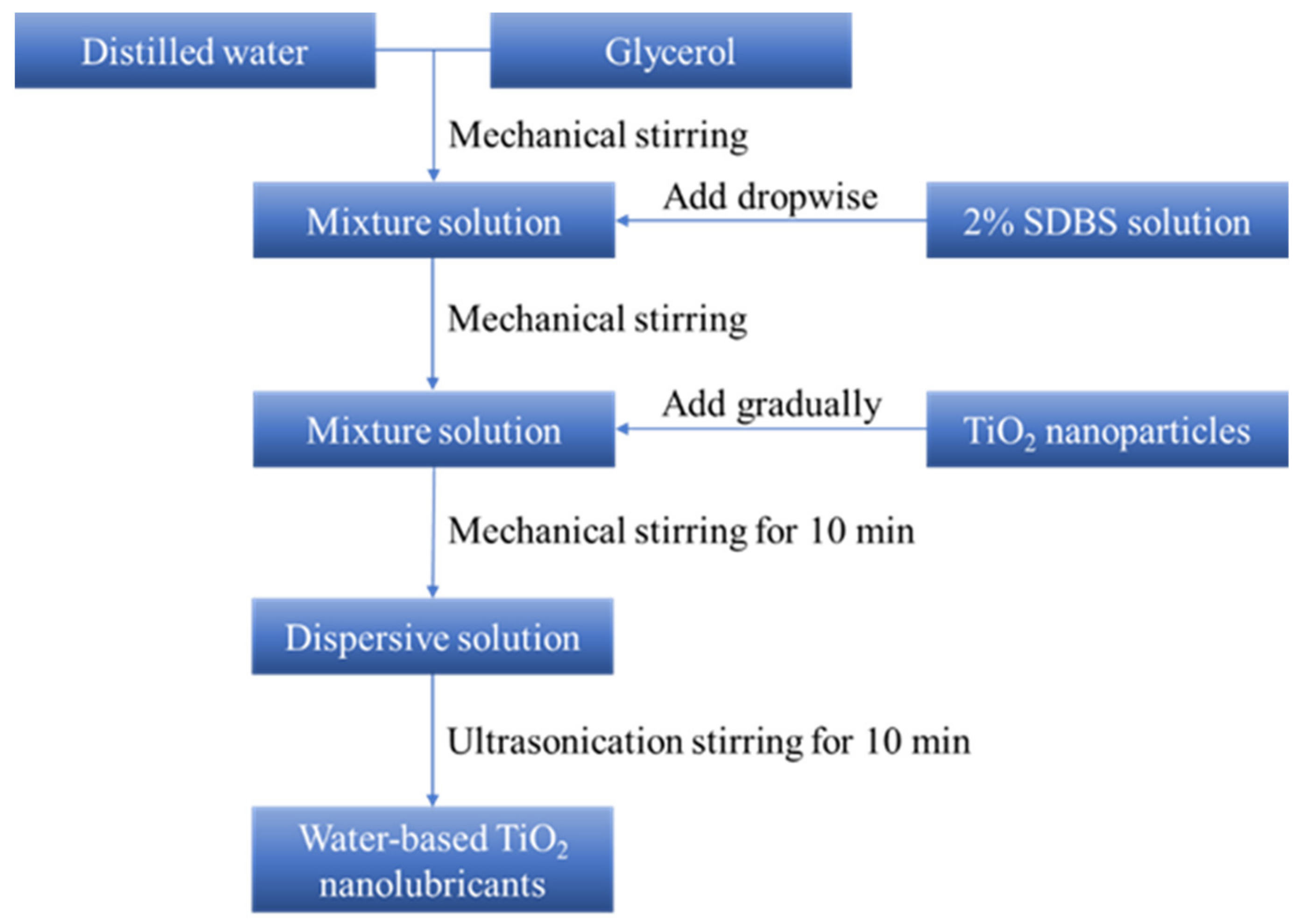
2.1. Material Preparation

The novel nano additive water-based lubricants are made of P25 TiO2 NPs, glycerol, sodium dodecyl-benzene sulfonate (SDBS) and balanced water. All additives are non-toxic materials and environmentally friendly. P25 TiO2 NPs is a mixture which composed of 75% anatase and 25% rutile with approximately 20 nm in diameter [32]. Glycerol is a colourless, odorless, viscous liquid and miscible with water. Glycerol is used to enhance the viscosity of nanolubricants. SDBS is a white to light yellow sand-like solid which could be easily rinsed off the surface of the material. Its solution is used as a dispersing agent to improve the dispersion stability and viscosity of nanolubricants [33]. The water-based TiO2 nanolubricants were prepared according to the flow chart shown in Figure 1. The dropwise glycerol and SDBS solution were first added into the distilled water followed by stirring with a dropper. Next, the TiO2 NPs were gradually added into the solution and then mechanical stirred for 10 min until no obvious agglomeration appears. Afterwards, the remaining agglomeration in the dispersive solution was eliminated by ultrasonication for 10 min. Finally, the water-based TiO2 nanolubricants with excellent dispersion stability were prepared. Four groups of lubrication conditions were designed according to the chemical compositions of the nanolubricants, as shown in Table 1. In this study, the pure titanium foil with the thickness of 40 μm was used and its chemical compositions are listed in Table 2. As a comparison, the dry friction condition was also designed in this study.

2.2. Micro Deep Drawing

In this study, a desktop servo-press machine DT-3AW (Keyence Corporation, Osaka, Japan) was used for MDD process. As shown in Figure 2, the MDD system contains press machine, die sets and control box. The die sets consist of the upper and lower dies where the punch and cavity are placed. The press machine provides the load, and the control box is used to set the operation of the press machine and obtain the position of punch during the process. The real-time drawing force is recorded by a load cell which is located on the top of the upper die. In this study, the MDD process includes two stages: blanking and drawing. In the blanking stage, a round blank with the radius of 0.8 mm was cut from the pure titanium foils, and subsequently the round blank was drawn with a velocity of 0.1 mm/s. The geometrical dimensions of the MDD system are shown in Figure 2e. The friction between the blank and the lower die dominates the total friction force and ultimately affects the drawing force. Therefore, two drops (approx. 0.1 mL) of the water-based TiO2 nanolubricants were dripped into the cavity of the lower die before the MDD process, as shown in Figure 2f. The MDD process was repeated five times for each test to minimise the data scattering of the drawing force.

2.3. Observations

The sedimentation analysis method was used to measure the dispersion stability of water-based TiO2 nanolubricants. The nanolubricants were photographed every 24 h. The sedimentation phenomenon of TiO2 NPs and the appearance of supernatant were then recorded.
The phase and morphology of the P25 TiO2 NPs were characterised by X-ray diffractometer (XRD, GBC Scientific Equipment Pty Ltd., Melbourne, Australia), JEOLTM JEM-ARM200F transmission electron microscope (TEM, JEOL Ltd., Tokyo, Japan) and JEOLTM JSM-7001F field emission scanning electron microscope (SEM, JEOL Ltd., Tokyo, Japan). The SEM equipped with the energy dispersive spectroscopy (EDS, JEOL Ltd., Tokyo, Japan) was used to analyse the distribution of elements. In addition, the distribution of TiO2 NPs on the micro cups was observed by SEM to explore the lubrication mechanism.
The surface roughness and dimensions of the micro cups were observed by KEYENCETM VK-X100K 3D laser scanning microscope (Keyence Corporation, Osaka, Japan). To ensure the reliability and accuracy of the data, four regions on each drawn cups were randomly selected to measure the surface roughness values.

3. Results and Discussion

3.1. Material Characterisation

The XRD pattern of the P25 TiO2 NPs is shown in Figure 3. The phase of the particles can be identified as typical P25 TiO2 with 75% of anatase and 25% of rutile based on the XRD standard atlas.
Figure 4 shows the TEM images of the P25 TiO2 NPs with different concentrations of water-based nanolubricants from 0.5 to 2.0 wt%. It can be observed that the P25 TiO2 NPs are almost spherical with an average size of about 20 nm. The P25 TiO2 NPs are uniformly distributed and show excellent dispersion stability with no significant aggregations even at high concentrations such as 2.0 wt%. The nanolubricants with good dispersion stability are expected to provide a stable lubrication performance in the MDD process.
Photographs of the nanolubricants in a period of time are shown in Figure 5. Regardless of the concentration of TiO2 NPs, all the nanolubricants remain stable for 24 h with insignificant NPs sedimentation at the bottom. After 24 h, the nanolubricants begin to settle slightly and a shallow supernatant appears (Figure 5c,d). This indicates that the water-based TiO2 nanolubricants have excellent dispersion stability. Stable nanolubricant is usually considered as a prerequisite for the successful application in the MDD process.

3.2. Drawing Force

The average drawing force and displacement curves were obtained, as shown in Figure 6. It indicates that the largest peak drawing force appears in the group when 2.0 wt% nanolubricant was used while the other groups share similar and relatively lower values in the peak drawing force. This is due to the resistance of bending that dominates the maximum drawing force initially [34]. With the increase of drawing depth, the drawing force drops drastically at the end of the MDD process. When the micro cup fully enters the cavity of the lower die [35], there is a significant decrease in the final drawing force after the utilisation of lubricant.
The maximum drawing force and the final drawing force for each group were summarised in Figure 7. As analysed previous, there is an insignificant change in the peak drawing force as the drawing force is dominated by the resistance of bending before a full cup shape is formed. The effect of the 0.5% and 1.0% nanolubricants on maximum drawing force is insignificant. For the 2.0% nanolubricant, the peak drawing force (42.94 N) increases slightly as the TiO2 NPs agglomeration impedes the material flow. It is evident that the highest final drawing force value (6.97 N) is found in the dry condition among all the lubrication conditions. For the final drawing force, the lubrication effect of the 0.5% and 1.0% nanolubricants is obvious, which achieves reductions of 12.7% and 24.2%, respectively, compared with that in dry condition. In addition, the final drawing force experiences a relatively lower drop to 6.67 N when the 2.0 wt% nanolubricant is employed.

3.3. Quality Evaluation of Micro Cups

The surface roughness is an important parameter to evaluate the forming quality of the micro cups. Figure 8 shows the 3D surface morphology of the micro cups from different lubrication conditions. As can be seen in Figure 8a, considerable bumps are observable on the cup surface without the use of nanolubricants and the measured surface is the roughest among four groups. For Groups 2, 3 and 4, the surface quality of the micro cups has been improved from the observation of Figure 8b–d. It is worth noting that the micro cups from Group 3 have the smoothest surface, which displays the least surface peaks and valleys. In addition, the surface quality of the micro cup from Group 4 shows a slight improvement compared with that from dry conditions, but not as evident as those from Groups 2 and 3. Based on the 3D surface morphology, the surface roughness values of the micro cups from four groups were summarised in Figure 9. For MDD process, the nanolubricant with 1.0 wt% TiO2 NPs shows the best lubrication capability in achieving a good surface quality by reducing the surface roughness value of 12.55% compared with that obtained under dry condition.
Wrinkling is an important feature to evaluate the forming quality of the micro cups. Less wrinkles mean better forming quality and higher shape accuracy. During the MDD process, the blank undergoes large radial drawing stress and tangential compressive stress [36]. The surface roughness affects the metal flow behaviour, thereby affecting the forming performance [2]. A large surface roughness will cause the difficulty in material flow and induce more winkles [9]. To clearly exhibit the reduction of wrinkles, the difference between the outer diameter and the minimum inner diameter of the micro cups is defined as the maximum distance, and the difference between the outer and maximum inner diameters of the micro cups is defined as the minimum distance [2], as shown in Figure 10. The amount of wrinkle is calculated by dividing the difference between the maximum and minimum distances by the maximum distance. Figure 11 shows the top views of the micro cups under various lubrication conditions. It can be seen that obvious wrinkling occurs on the flange of the micro cup under dry condition, as shown in Figure 11a. The number of wrinkles is significantly reduced with the use of nanolubricant, especially for the cup from Group 3 (Figure 11c), from which the winkles are hardly seen on the edge of parts. The wrinkles of micro cups obtained using various nanolubricants are summarised in Figure 12. The wrinkles decreased from 15.47% to 14.73% when the 1.0 wt% TiO2 nanolubricant was used, showing an improvement of 4.82%.

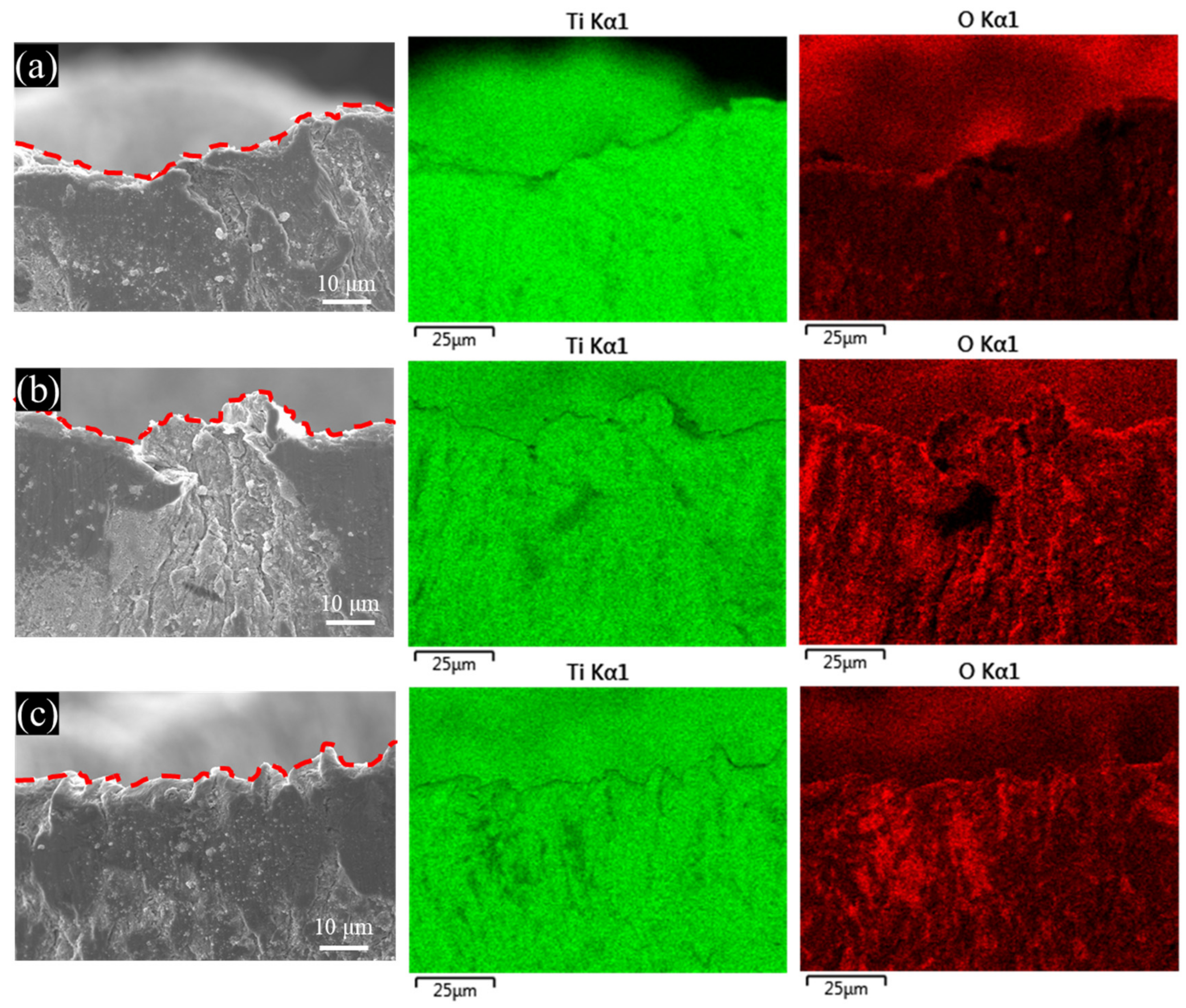
3.4. Surface Observation

Figure 13 shows the SEM images and EDS mappings of the side view of the drawn cups under different lubrication conditions. Since both titanium foil and TiO2 NPs contain the element of titanium, the distribution of TiO2 NPs could be determined by the distribution of oxygen element. When the 0.5 wt% nanolubricant is applied, the distribution of TiO2 NPs on the micro cup is observable but not as noticeable as that indicated under other lubrication conditions. As the concentration of nanolubricant increases from 0.5 to 2.0 wt%, there is a significant increase in the number of TiO2 NPs on the surface of the drawn cups according to the EDS mappings. In order to investigate the lubrication mechanism of the TiO2 NPs on the micro cups surface, three areas on the micro cup wall were selected from each micro cup and marked as Areas A, B and C.
SEM images with higher magnification and EDS spectrum (×10,000) of the Areas A, B and C were selected to explore the lubrication mechanism of TiO2 NPs in MDD process, as shown in Figure 14. The distribution of TiO2 NPs on the surface and the agglomeration in the roughness valleys can be clearly observed according to the SEM images. The corresponding EDS spectrums of the TiO2 NPs were also detected and exhibited along with the SEM observation. As can be seen from Area A (Figure 14a), a few TiO2 NPs are distributed but not fully covered on the surface, especially in the CLPs area, which could result in the incomplete mending effect in this region. A portion of dispersed TiO2 NPs on the contact area can be used to bear the load by converting the sliding friction to the rolling friction, which reduces the rubbing between the tool and the workpiece. This phenomenon is called the rolling effect. As for the Area B shown in Figure 14b, the TiO2 NPs are evenly dispersed on the surface of the micro cup and the CLPs region are well filled with TiO2 NPs. This greatly enhances the synergism action of the rolling and mending effects, and further reduces the friction between the blank and the lower die. However, compared to the 0.5 and 1.0 wt% nanolubricants, excessive TiO2 NPs are provided to fill the CLPs region when the 2.0 wt% nanolubricant is applied, and the redundant TiO2 NPs are agglomerated on the surface of the material, as presented in Area C (Figure 14c). The agglomeration impedes the material flow during the MDD process and affects the further supply of the TiO2 NPs into the contact area, which results in a relatively poor lubrication performance.
The OLPs area is located in the mouth area of the drawn micro cup. Generally, the liquid lubricants will be squeezed out and make it hardly bear the applied load in this region. However, due to the high viscosity of the nanolubricant, the TiO2 NPs of the nanolubricants could remain in the OLPs area and thus provide a part of load bearing capacity. This thus leads to a reduction of the friction between the blank and the lower die. Figure 15 shows the SEM images and EDS mappings of the cup mouth area using different lubricants. Compared to the 0.5 and 2.0 wt% nanolubricants, the TiO2 NPs in the 1.0 wt% nanolubricant were more uniformly distributed at the OLPs area. For the 0.5 wt% nanolubricant, there are insufficient TiO2 NPs that provide load bearing capacity at the OLPs area. For the 2.0 wt% nanolubricant, more aggregations of TiO2 NPs were observed at the OLPs area. By comparison, it can be observed that there are a few TiO2 NPs that exist along the cup mouth area. Therefore, the friction near the mouth area reduces, and the winkles decrease significantly, which meets well with the observations in Figure 9. This phenomenon illustrates that the nanolubricants can effectively enhance the lubrication performance at the OLPs area.

3.5. Lubrication Mechanism

Figure 16 illustrates the lubrication mechanism of water-based TiO2 nanolubricants in the MDD process. The nanolubricants with excellent dispersion stability provide the necessary prerequisites for obtaining excellent lubrication performance between the blank and the lower die. Some TiO2 NPs worked as ball bearings to reduce the friction of real contact areas between the blank and the lower die. These TiO2 NPs rotate in the contact area during the MDD process, which results in a lower coefficient of friction than that obtained under dry conditions where the two surfaces slide directly against each other, as shown in Figure 16a,b. In addition, TiO2 NPs aggregate in the CLPs area, and thus the pits and valleys on the cup surface can be compensated by the mending effect of TiO2 NPs, resulting in a relatively lower surface roughness, as shown in Figure 16c,d. In this study, as the concentration of TiO2 NPs increases from 0.5 to 1.0 wt%, more TiO2 NPs effectively participate in the MDD process in the contact area and CLPs areas, which enables the lubrication performance to gradually improve. However, further increasing the TiO2 NPs concentration to 2.0 wt% will cause excessive aggregation of TiO2 NPs, which leads to the increase in friction and decrease in forming quality. At the mouth area of the drawn cups, the TiO2 NPs can be kept in the OLPs area due to high viscosity of the nanolubricant. Hence, the remained nanolubricant could provide load bearing capacity and therefore result in a reduction in friction. In addition, the aggregation of the appropriate concentration of TiO2 NPs can reduce the shear stress in the contact area during MDD process, which also results in the reduction of friction on the material surface [37].

4. Conclusions

In this study, the MDD of pure titanium were carried out using 0.5, 1.0 and 2.0 wt% water-based nanolubricants to examine their lubrication performance. The forming quality of the micro drawn cups in terms of drawing force, surface roughness and shape accuracy was systematically evaluated. Finally, the lubrication mechanism of the nanolubricant in the MDD process was unveiled. The main conclusions can be drawn as follows.
(1)
The TEM images and sedimentation observations indicate the novel water-based TiO2 nanolubricants possess excellent dispersion stability.
(2)
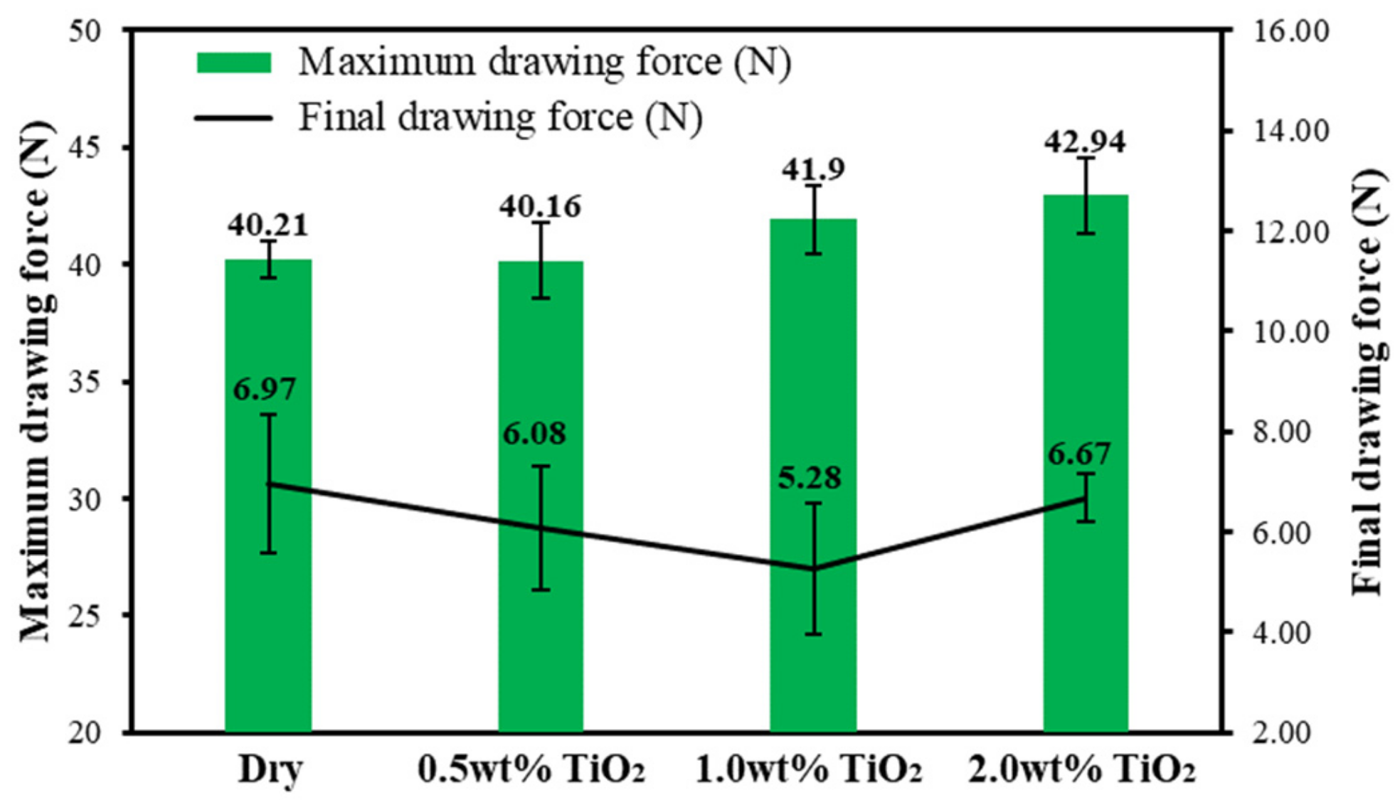
As for the final drawing force, the 1.0 wt% nanolubricants exhibit the best lubrication performance, resulting in a 24.2% reduction in the final drawing force compared to the dry condition.
(3)
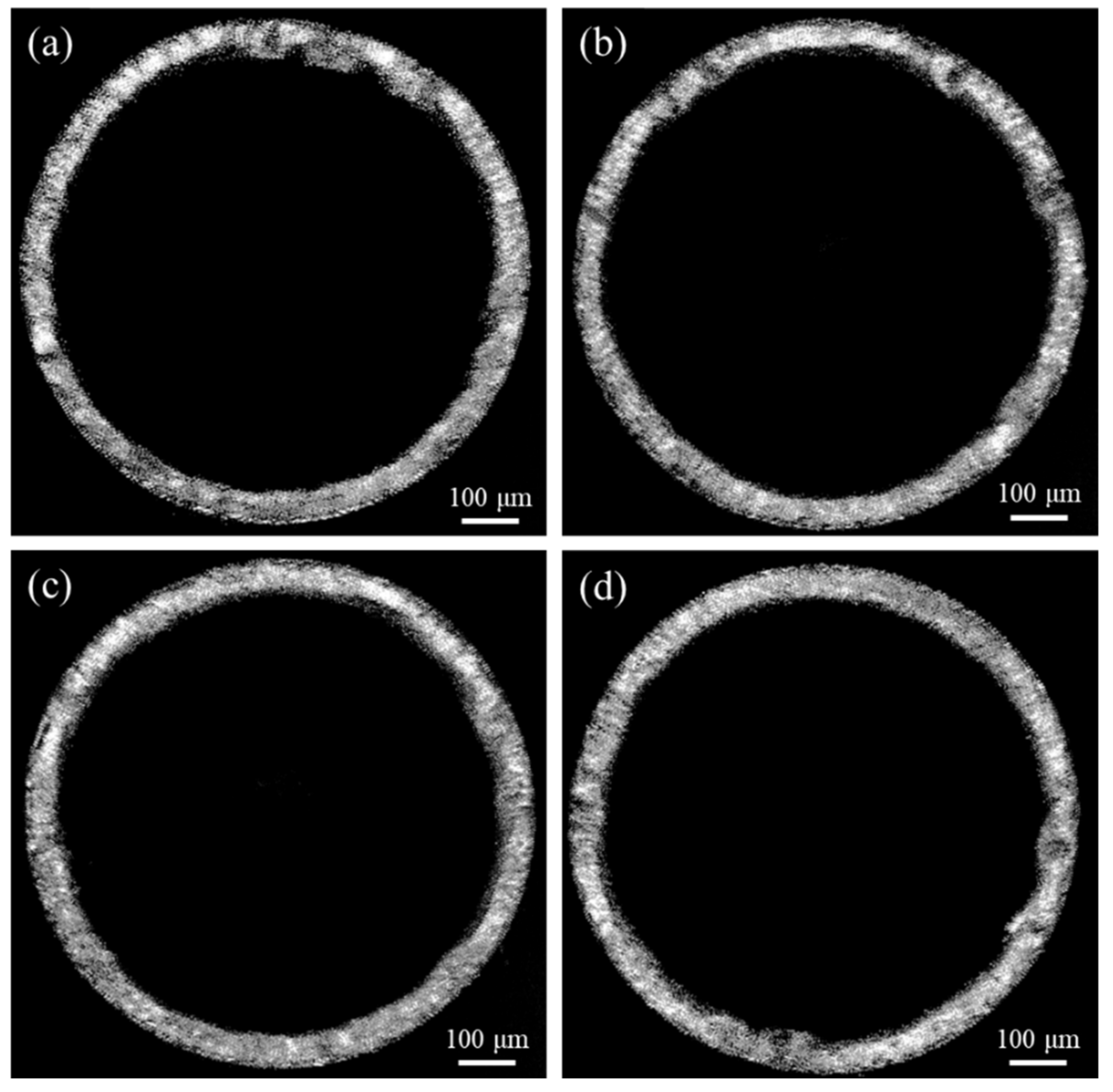
The 1.0 wt% nanolubricants show a significant improvement in the quality of the micro cups. There is a 12.55% reduction in the surface roughness compared to the dry condition. The wrinkles are decreased from 15.46% (dry conditions) to 14.73%.
(4)
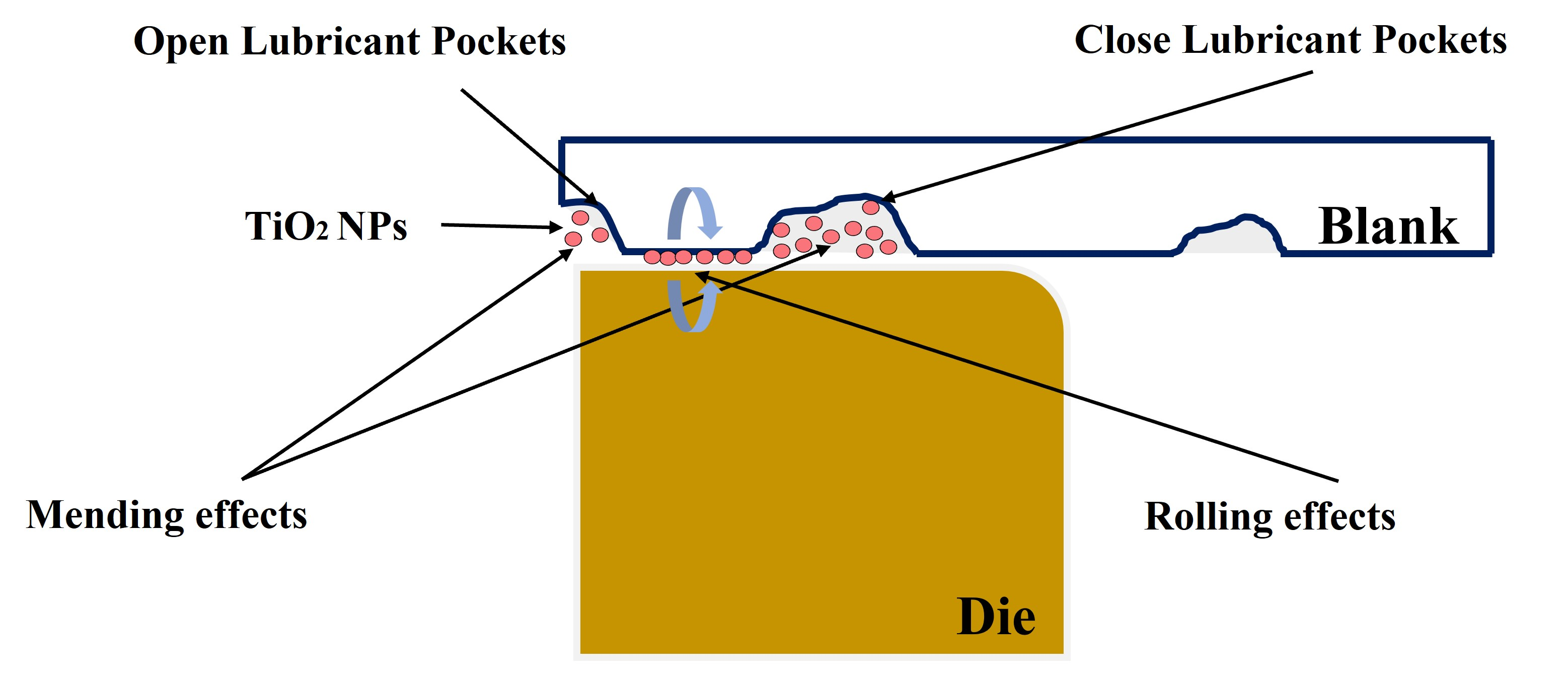
The TiO2 NPs can fill in the OLPs area and therefore provide load bearing capacity, resulting in a reduction in friction during MDD. At the CLPs area, the lubrication mechanism can be contributed by the synergistic effect of ball bearing and mending effect of the TiO2 NPs.

Author Contributions

M.Z. performed the experiments in addition to analysing the data and writing the paper; F.J. contributed to the SEM operation and editing; J.Y. contributed to proofreading; H.W. contributed to the supervision, experimental design, result analysis and revise the paper; Z.J. contributed to the conceptualization, supervision, funding acquisition, result analysis and editing. All authors have read and agreed to the published version of the manuscript.

Funding

This research was funded by the Australian Research Council (ARC, Grant Nos. DP190100738 and DP190100408).

Data Availability Statement

Not applicable.

Acknowledgments

The authors acknowledge the financial support from Australian Research Council (ARC, Grant Nos. DP190100738 and DP190100408). The authors are grateful to Matthew Franklin in the workshop of SMART Infrastructure Facility at the University of Wollongong for his great support on sample machining and preparation.

Conflicts of Interest

The authors declare no conflict of interest.

References

  1. Zhao, J.; Wang, T.; Jia, F.; Li, Z.; Zhou, C.; Huang, Q.; Jiang, Z. Experimental Investigation on Micro Deep Drawing of Stainless Steel Foils with Different Microstructural Characteristics. Chin. J. Mech. Eng. 2021, 34, 11. [Google Scholar] [CrossRef]
  2. Jiang, Z.; Zhao, J.; Xie, H. Microforming Technology Theory, Simulation and Practice, 1st ed.; Academic Press: London, UK, 2017. [Google Scholar]
  3. Hasan, M.; Zhao, J.; Jiang, Z. Micromanufacturing of composite materials: A review. Int. J. Extreme Manuf. 2019, 1, 26. [Google Scholar] [CrossRef]
  4. Luo, L.; Jiang, Z.; Wei, D.; Manabe, K.-I.; Zhao, X.; Wu, D.; Furushima, T. Effects of surface roughness on micro deep drawing of circular cups with consideration of size effects. Finite Elements Anal. Des. 2016, 111, 46–55. [Google Scholar] [CrossRef] [Green Version]
  5. Chinchanikar, S.; Kolte, Y. A review on experimental and numerical studies on micro deep drawing considering size effects and key process parameters. Aust. J. Mech. Eng. 2022, 14. [Google Scholar] [CrossRef]
  6. Gong, F.; Guo, B.; Wang, C.; Shan, D. Micro deep drawing of micro cups by using DLC film coated blank holders and dies. Diam. Relat. Mater. 2011, 20, 196–200. [Google Scholar] [CrossRef]
  7. Vollertsen, F.; Hu, Z. Analysis of punch velocity dependent process window in micro deep drawing. Prod. Eng. 2010, 4, 553–559. [Google Scholar] [CrossRef]
  8. Luo, L.; Wei, D.; Wang, X.; Zhou, C.; Huang, Q.; Xu, J.; Wu, D.; Jiang, Z. Effects of hydraulic pressure on wrinkling and earing in micro hydro deep drawing of SUS304 circular cups. Int. J. Adv. Manuf. Technol. 2016, 90, 189–197. [Google Scholar] [CrossRef] [Green Version]
  9. Luo, L.; Wei, D.; Zu, G.; Jiang, Z. Influence of blank holder-die gap on micro-deep drawing of SUS304 cups. Int. J. Mech. Sci. 2020, 191, 106065. [Google Scholar] [CrossRef]
  10. Tan, X. Comparisons of friction models in bulk metal forming. Tribol. Int. 2002, 35, 385–393. [Google Scholar] [CrossRef]
  11. Peng, L.; Lai, X.; Lee, H.-J.; Song, J.-H.; Ni, J. Friction behavior modeling and analysis in micro/meso scale metal forming process. Mater. Des. 2010, 31, 1953–1961. [Google Scholar] [CrossRef]
  12. Vollertsen, F.; Hu, Z.; Niehoff, H.; Theiler, C. State of the art in micro forming and investigations into micro deep drawing. J. Mater. Process. Technol. 2004, 151, 70–79. [Google Scholar] [CrossRef]
  13. Han, J.; Zheng, W.; Wang, G.; Yu, M. Experimental study on size effect of dry friction in meso/micro-upsetting process. Int. J. Adv. Manuf. Technol. 2017, 95, 1127–1133. [Google Scholar] [CrossRef]
  14. Engel, U. Tribology in microforming. Wear 2006, 260, 265–273. [Google Scholar] [CrossRef]
  15. Chan, W.; Fu, M.; Lu, J. The size effect on micro deformation behaviour in micro-scale plastic deformation. Mater. Des. 2011, 32, 198–206. [Google Scholar] [CrossRef]
  16. Hu, Z.; Schubnov, A.; Vollertsen, F. Tribological behaviour of DLC-films and their application in micro deep drawing. J. Mater. Process. Technol. 2012, 212, 647–652. [Google Scholar] [CrossRef]
  17. Wang, C.; Guo, B.; Shan, D.; Bai, X. Experimental research on micro-deep drawing processes of pure gold thin sheet using DLC-coated female die. Int. J. Adv. Manuf. Technol. 2012, 67, 2477–2487. [Google Scholar] [CrossRef]
  18. Rahman, M.H.; Warneke, H.; Webbert, H.; Rodriguez, J.; Austin, E.; Tokunaga, K.; Rajak, D.K.; Menezes, P.L. Water-Based Lubricants: Development, Properties, and Performances. Lubricants 2021, 9, 73. [Google Scholar] [CrossRef]
  19. Cui, X.; Li, C.; Ding, W.; Chen, Y.; Mao, C.; Xu, X.; Liu, B.; Wang, D.; Li, H.N.; Zhang, Y.; et al. Minimum quantity lubrication machining of aeronautical materials using carbon group nanolubricant: From mechanisms to application. Chin. J. Aeronaut. 2021, 35, 85–112. [Google Scholar] [CrossRef]
  20. He, Y.; Wang, L.; Wu, T.; Wu, Z.; Chen, Y.; Yin, K. Facile fabrication of hierarchical textures for substrate-independent and durable superhydrophobic surfaces. Nanoscale 2022, 14, 9392–9400. [Google Scholar] [CrossRef] [PubMed]
  21. He, A.; Huang, S.; Yun, J.-H.; Wu, H.; Jiang, Z.; Stokes, J.; Jiao, S.; Wang, L.; Huang, H. Tribological Performance and Lubrication Mechanism of Alumina Nanoparticle Water-Based Suspensions in Ball-on-Three-Plate Testing. Tribol. Lett. 2017, 65, 40. [Google Scholar] [CrossRef]
  22. Wu, H.; Zhao, J.; Xia, W.; Cheng, X.; He, A.; Yun, J.H.; Wang, L.; Huang, H.; Jiao, S.; Huang, L.; et al. A study of the tribological behaviour of TiO2 nano-additive water-based lubricants. Tribol. Int. 2017, 109, 398–408. [Google Scholar] [CrossRef] [Green Version]
  23. Wu, H.; Jia, F.; Li, Z.; Lin, F.; Huo, M.; Huang, S.; Sayyar, S.; Jiao, S.; Huang, H.; Jiang, Z. Novel water-based nanolubricant with superior tribological performance in hot steel rolling. Int. J. Extreme Manuf. 2020, 2, 025002. [Google Scholar] [CrossRef]
  24. Wu, H.; Wei, D.; Hee, A.C.; Huang, S.; Xing, Z.; Jiao, S.; Huang, H.; Jiang, Z. The influence of water-based nanolubrication on mill load and friction during hot rolling of 304 stainless steel. Int. J. Adv. Manuf. Technol. 2022, 121, 7779–7792. [Google Scholar] [CrossRef]
  25. Wu, H.; Zhao, J.; Cheng, X.; Xia, W.; He, A.; Yun, J.-H.; Huang, S.; Wang, L.; Huang, H.; Jiao, S.; et al. Friction and wear characteristics of TiO2 nano-additive water-based lubricant on ferritic stainless steel. Tribol. Int. 2018, 117, 24–38. [Google Scholar]
  26. Wu, H.; Zhao, J.; Luo, L.; Huang, S.; Wang, L.; Zhang, S.; Jiao, S.; Huang, H.; Jiang, Z. Performance Evaluation and Lubrication Mechanism of Water-Based Nanolubricants Containing Nano-TiO2 in Hot Steel Rolling. Lubricants 2018, 6, 57. [Google Scholar] [CrossRef] [Green Version]
  27. Kamali, H.; Xie, H.; Jia, F.; Wu, H.; Zhao, H.; Zhang, H.; Li, N.; Jiang, Z. Effects of nano-particle lubrication on micro deep drawing of Mg-Li alloy. Int. J. Adv. Manuf. Technol. 2019, 104, 4409–4419. [Google Scholar] [CrossRef]
  28. Haus, F.; German, J.; Junter, G.-A. Primary biodegradability of mineral base oils in relation to their chemical and physical characteristics. Chemosphere 2001, 45, 983–990. [Google Scholar] [CrossRef]
  29. Kamali, H.; Xie, H.; Zhao, H.; Jia, F.; Wu, H.; Jiang, Z. Frictional Size Effect of Light-Weight Mg–Li Alloy in Micro Deep Drawing under Nano-Particle Lubrication Condition. Mater. Trans. 2020, 61, 239–243. [Google Scholar] [CrossRef]
  30. Huo, M.; Wu, H.; Xie, H.; Zhao, J.; Su, G.; Jia, F.; Li, Z.; Lin, F.; Li, S.; Zhang, H.; et al. Understanding the role of water-based nanolubricants in micro flexible rolling of aluminium. Tribol. Int. 2020, 151, 106378. [Google Scholar] [CrossRef]
  31. Sun, J.L.; Zhu, Z.X.; Xu, P.F. Study on the Lubricating Performance of Nano-TiO2 in Water-Based Cold Rolling Fluid. Mater. Sci. Forum 2015, 817, 219–224. [Google Scholar] [CrossRef]
  32. Wu, H.; Kamali, H.; Huo, M.; Lin, F.; Huang, S.; Huang, H.; Jiao, S.; Xing, Z.; Jiang, Z. Eco-Friendly Water-Based Nanolubricants for Industrial-Scale Hot Steel Rolling. Lubricants 2020, 8, 96. [Google Scholar] [CrossRef]
  33. Wu, K.; Zhang, Y.; Ge, F.; Huang, X.; Ge, H.H.; Zhao, Y.Z.; Meng, X.J.; Dou, B.L. Corrosion behavior of brass in SCW-SDBS-TiO2 nanofluid. J. Alloy. Compd. 2021, 855, 9. [Google Scholar] [CrossRef]
  34. Luo, L.; Jiang, Z.; Wei, D.; Manabe, K.-I.; Sato, H.; He, X.; Li, P. An experimental and numerical study of micro deep drawing of SUS304 circular cups. Manuf. Rev. 2015, 2, 27. [Google Scholar] [CrossRef] [Green Version]
  35. Luo, L.; Jiang, Z.; Wei, D. Influences of micro-friction on surface finish in micro deep drawing of SUS304 cups. Wear 2017, 374, 36–45. [Google Scholar] [CrossRef]
  36. Wei, D.; Luo, L.; Sato, H.; Jiang, Z.; Manabe, K. Simulations of hydro-mechanical deep drawing using Voronoi model and real microstructure model. Procedia Eng. 2017, 207, 1033–1038. [Google Scholar] [CrossRef]
  37. Wu, Y.; Tsui, W.; Liu, T. Experimental analysis of tribological properties of lubricating oils with nanoparticle additives. Wear 2007, 262, 819–825. [Google Scholar] [CrossRef]
Figure 1. The flow chart of preparation of water-based TiO2 nanolubricants.
Lubricants 10 00292 g001
Figure 2. Micro deep drawing system (a) press machine, (b) control box, (c) upper die, (d) lower die, (e) dimension of the system and (f) the supply method of nanolubricants.
Lubricants 10 00292 g002
Figure 3. XRD pattern of P25 TiO2 NPs.
Lubricants 10 00292 g003
Figure 4. TEM images of P25 TiO2 NPs with different concentrations of water-based nanolubricants: (a) 0.5 wt%, (b) 1.0 wt%, and (c) 2.0 wt%.
Lubricants 10 00292 g004
Figure 5. P25 TiO2 NPs dispersed in different water-based nanolubricants at time of (a) 0 h, (b) 24 h, (c) 48 h, and (d) 72 h.
Lubricants 10 00292 g005
Figure 6. The displacement and drawing force curves obtained under various lubrication conditions.
Lubricants 10 00292 g006
Figure 7. The comparison of maximum and final drawing forces under various lubrication conditions.
Lubricants 10 00292 g007
Figure 8. 3D surface morphologies of micro cups from four conditions (a) dry condition, (b) 0.5 wt% TiO2, (c) 1.0 wt% TiO2, and (d) 2.0 wt% TiO2.
Lubricants 10 00292 g008
Figure 9. The surface roughness of micro cups from various lubrication conditions.
Lubricants 10 00292 g009
Figure 10. Definitions for parameters of wrinkle.
Lubricants 10 00292 g010
Figure 11. Top views of the micro cups under various nanolubricants (a) dry condition, (b) 0.5 wt% TiO2, (c) 1.0 wt% TiO2, and (d) 2.0 wt% TiO2.
Lubricants 10 00292 g011
Figure 12. Wrinkles (%) of the micro cups under various lubrication conditions.
Lubricants 10 00292 g012
Figure 13. SEM images and EDS mappings of side view of the drawn cups using different lubricants: (a) 0.5 wt% TiO2, (b) 1.0 wt% TiO2, and (c) 2.0 wt% TiO2.
Lubricants 10 00292 g013
Figure 14. SEM images and EDS spectrums of the drawn cups with different lubricants (a) 0.5 wt% TiO2, (b) 1.0 wt% TiO2, and (c) 2.0 wt% TiO2.
Lubricants 10 00292 g014
Figure 15. SEM images and EDS mappings of mouth area of the micro cups with different lubricants (a) 0.5 wt% TiO2, (b) 1.0 wt% TiO2, and (c) 2.0 wt% TiO2.
Lubricants 10 00292 g015
Figure 16. The schematic view of the nanolubricant mechanism during MDD process (a,b) rolling/ball bearing mechanism, (c,d) mending effects.
Lubricants 10 00292 g016
Table 1. Chemical compositions of applied lubricants.
TypeDescription
Group 1Dry condition
Group 20.5 wt% TiO2 + 10 wt% Glycerol + 0.1 wt% SDBS + Balanced water
Group 31.0 wt% TiO2 + 10 wt% Glycerol + 0.1 wt% SDBS + Balanced water
Group 42.0 wt% TiO2 + 10 wt% Glycerol + 0.1 wt% SDBS + Balanced water
Table 2. Chemical compositions of the pure titanium foils (wt%).
MaterialsFeCNHO
Pure titanium0.200.080.030.0150.18
Publisher’s Note: MDPI stays neutral with regard to jurisdictional claims in published maps and institutional affiliations.

