Study of the Contact Characteristics of Machine Tool Spindle Bearings under Strong Asymmetric Loads and High-Temperature Lubrication Oil


Abstract
:1. Introduction
2. Analysis of the Mechanical Characteristics of Angular Contact Ball Bearings Considering Thermal Effects
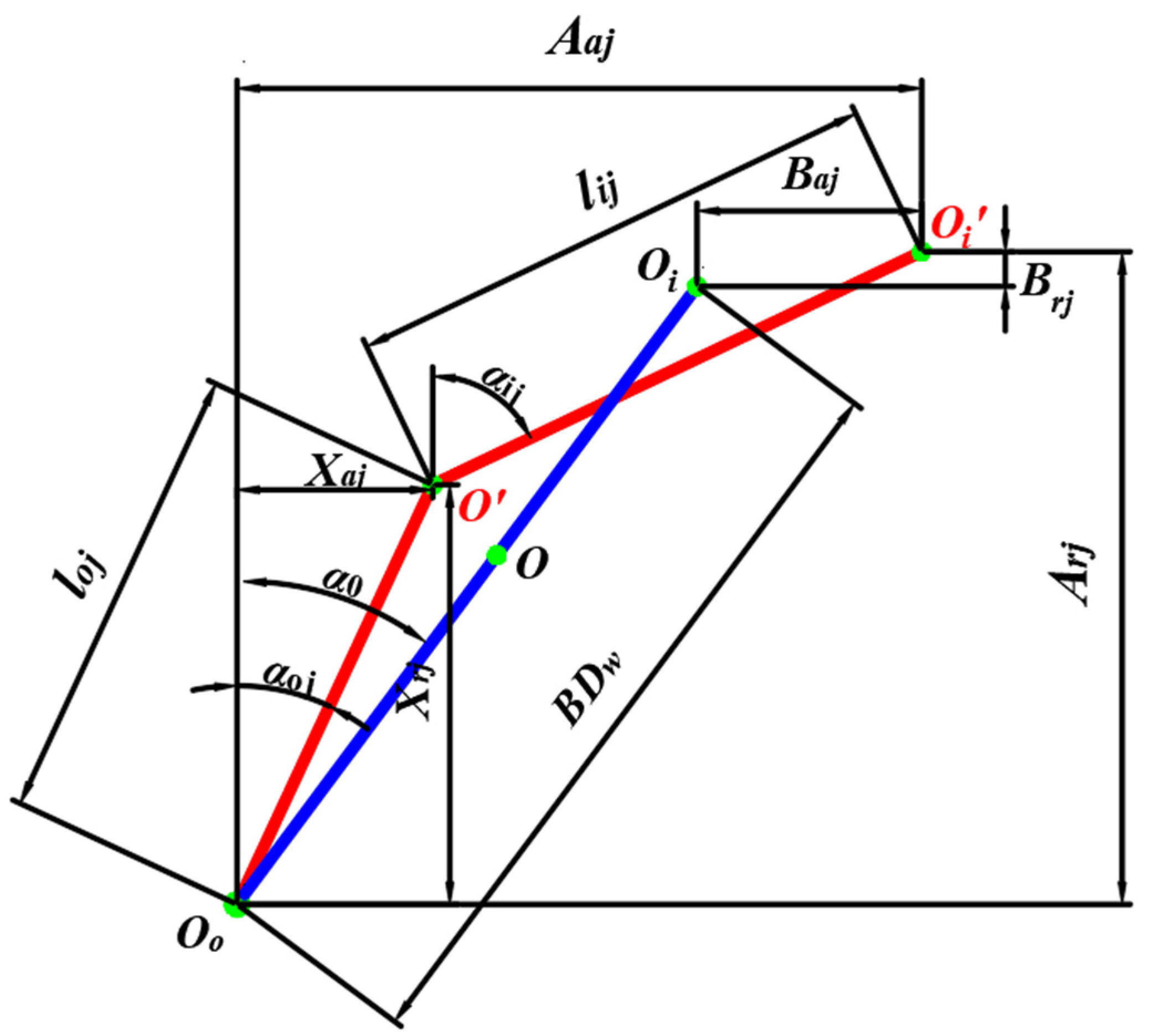
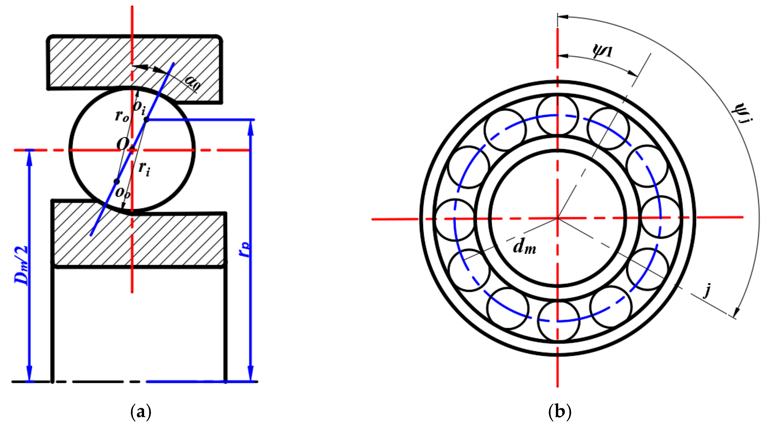
2.1. Geometric Analysis
2.2. Deformation Analysis
2.2.1. Heat-Induced Deformation
- (1)
- Displacement due to thermal expansion of the outer ring
- (2)
- Displacement due to thermal expansion of the ball
2.2.2. Centrifugal Deformation
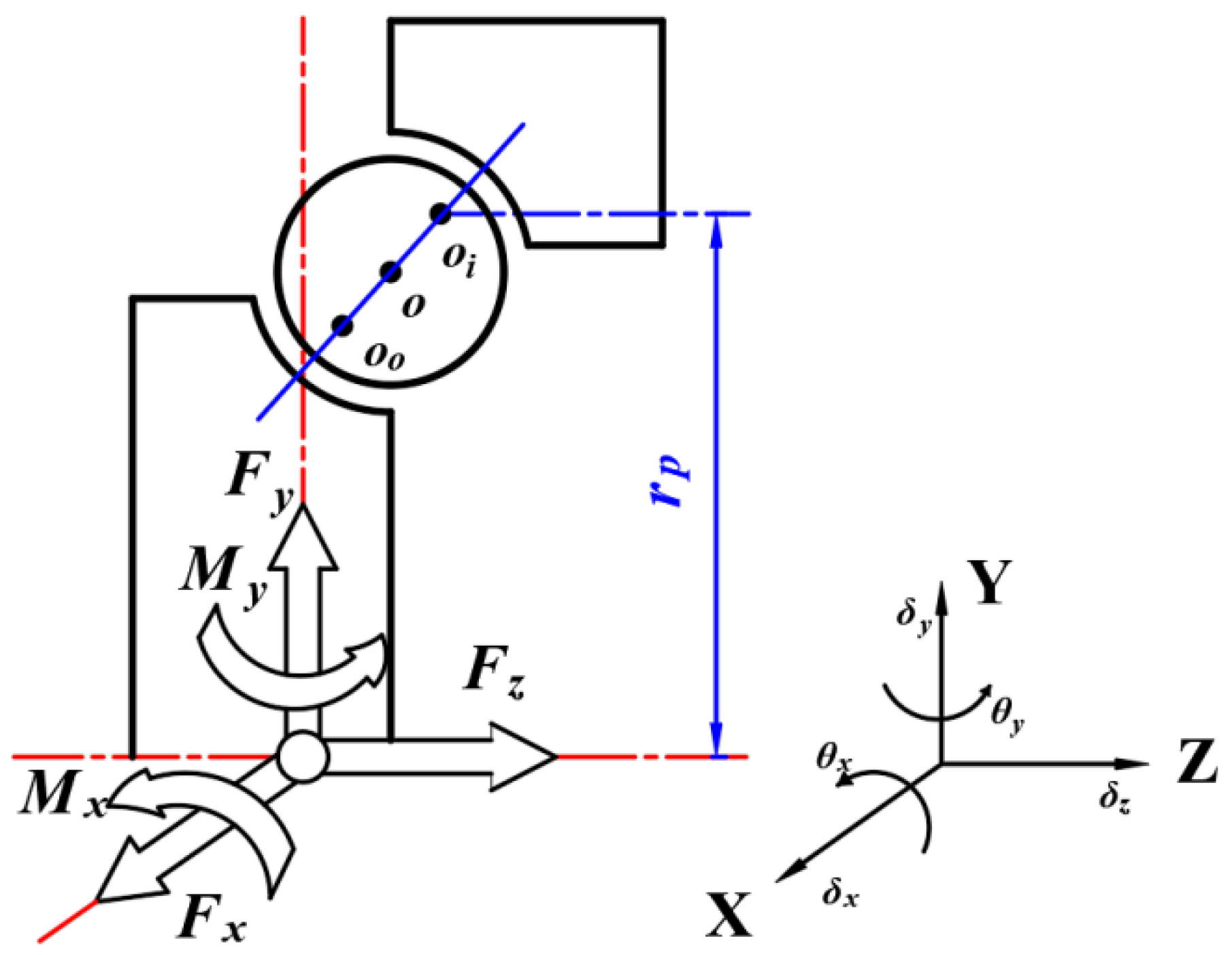
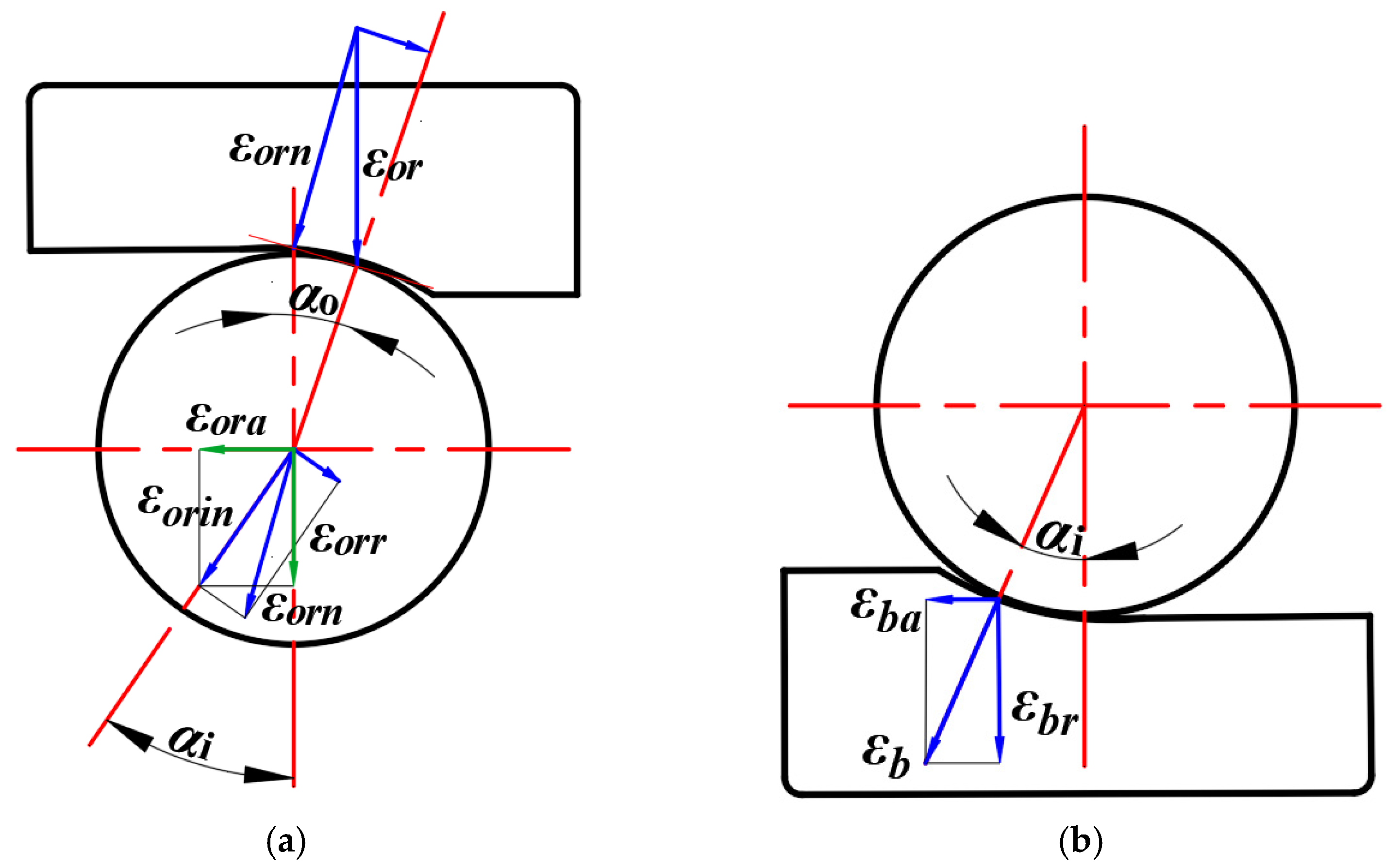
2.3. Force Analysis
3. Thermal Analysis of Spindle Bearing Systems
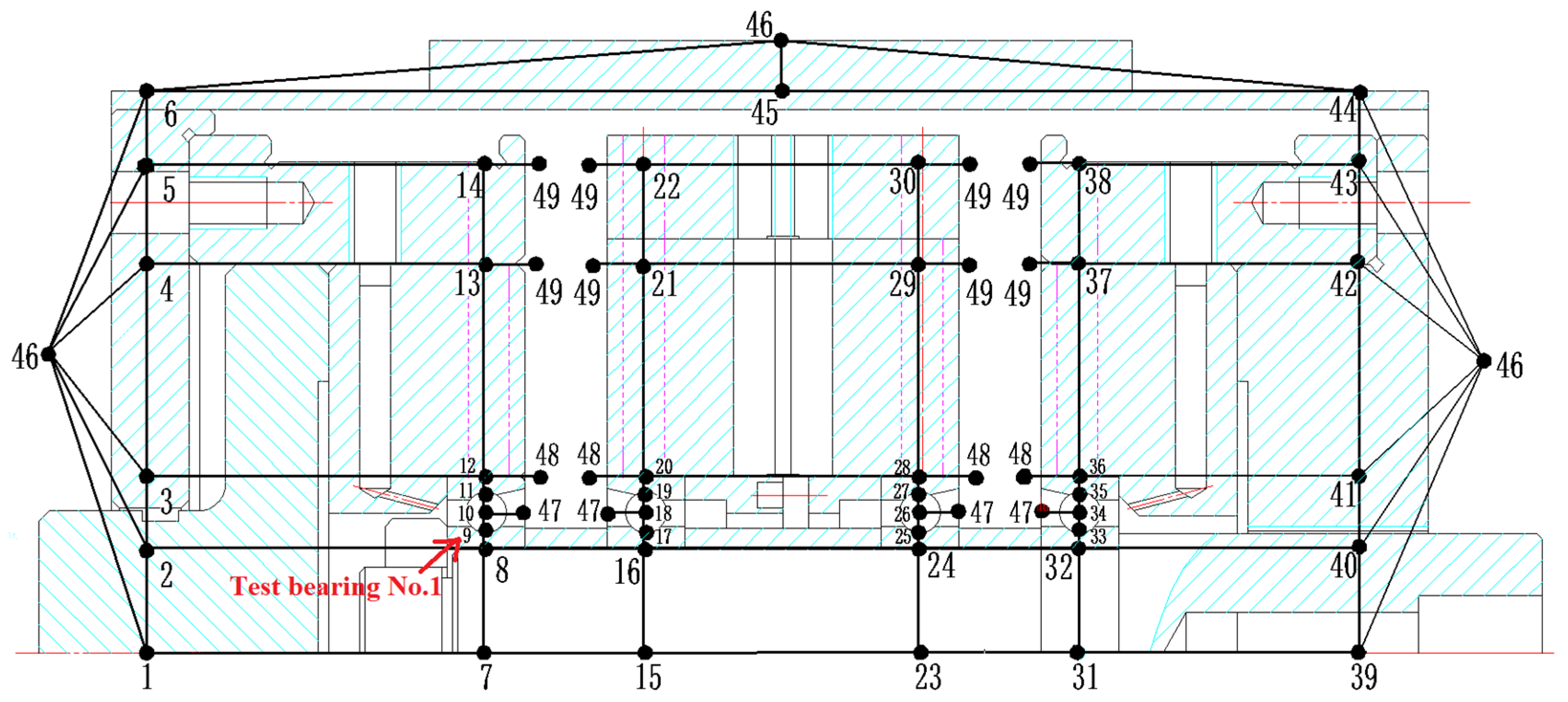
3.1. Heat Balance Equation and Nodes Planning
3.2. Heat Generation
- (1)
- Frictional torque M1 due to elastic hysteresis
- (2)
- Frictional torque M2 due to differential sliding
- (3)
- Frictional torque M3 due to spin-slip
- (4)
- Frictional torque M4 caused by contact between ball and cage
- (5)
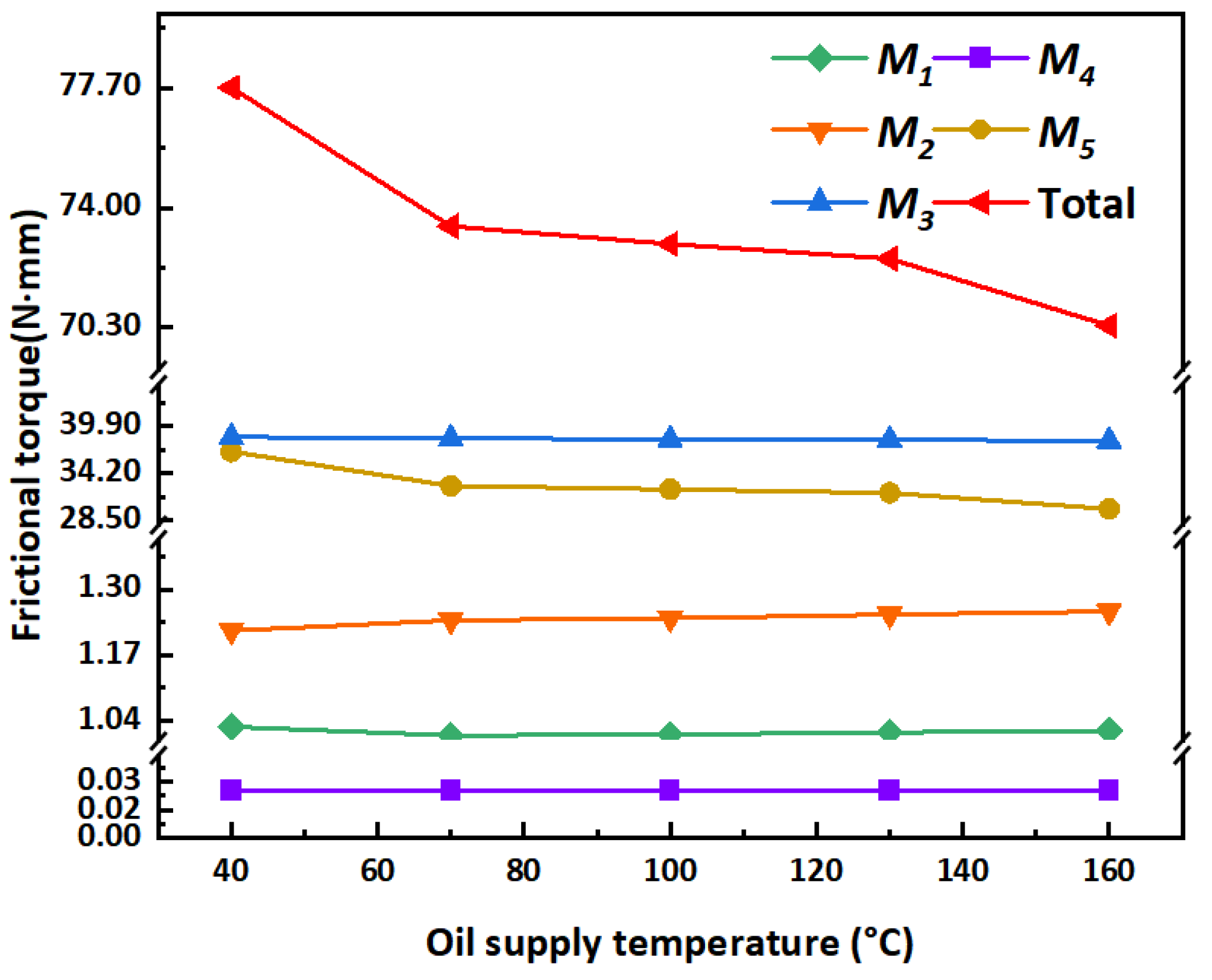
- Viscous friction torque M5 of the lubricantwhere β is the elastic hysteresis coefficient; fs is the sliding friction coefficient between ball and raceway; Web is the cage weight; fc is the sliding friction coefficient between ball and cage; aoil is the lubricant viscous pressure coefficient; S is the lubrication adequacy coefficient; hi(o) is the oil film thickness; φi(o)j, M2i(o)j are calculated in detail with reference to the literature [19]. The friction torque results for the closed-loop iterations are shown in Figure 7.
3.3. Heat Transfer Analysis
- (1)
- Heat conduction between the inner ring of the bearing and the shaft
- (2)
- Heat conduction between the ball and the inner and outer rings of the bearing
- (3)
- Heat conduction between bearing outer ring and housing
- (4)
- Heat conduction between bearing housing and spindle housing
- (5)
- Natural convection between spindle housing, end caps, etc., and ambient air
- (6)
- Forced convection between high-speed rotating surfaces and air in the system
- (7)
- Forced convection between the sides of high-speed rotating surfaces and air
- (8)
- Forced convection of coolant, lubricant, and flow-through surfaces
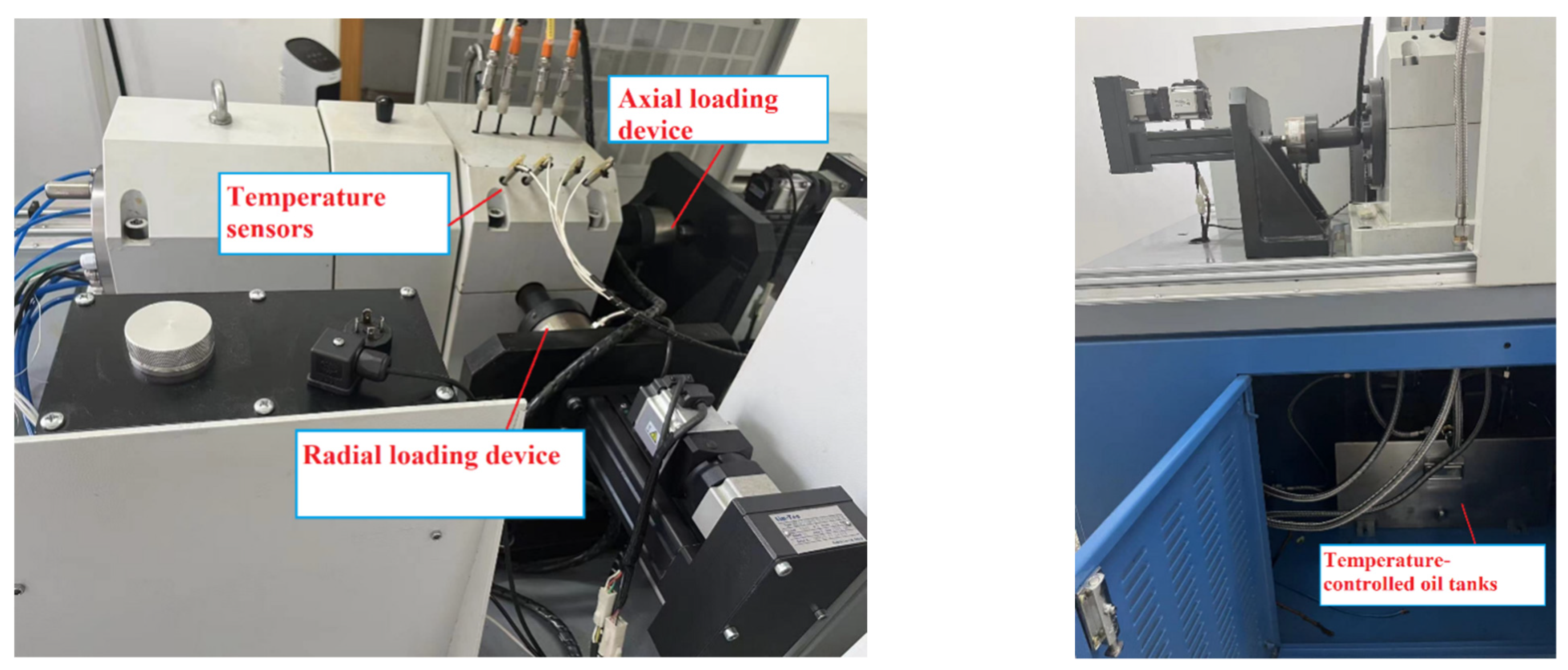
4. Experiment
5. Discussion
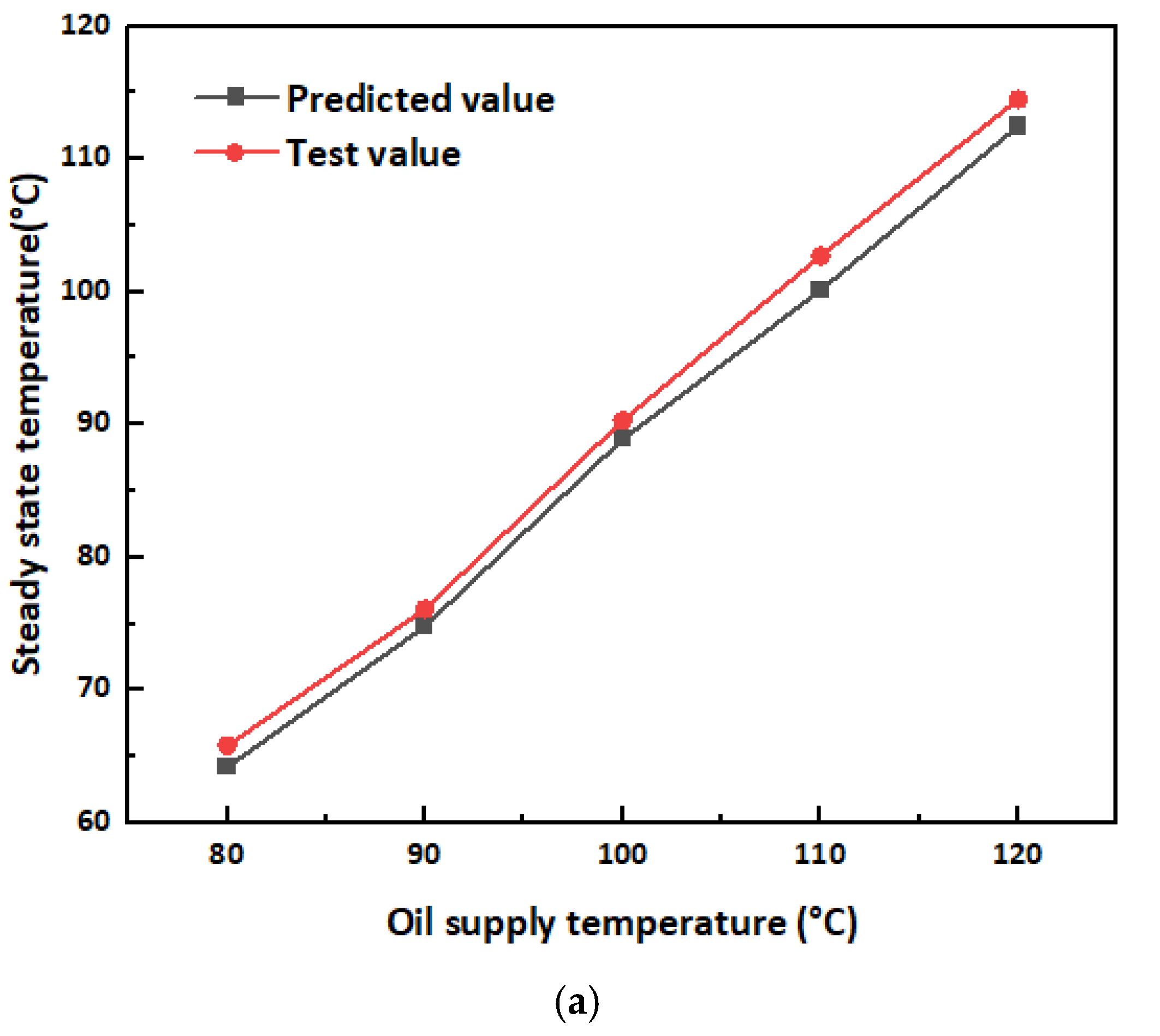
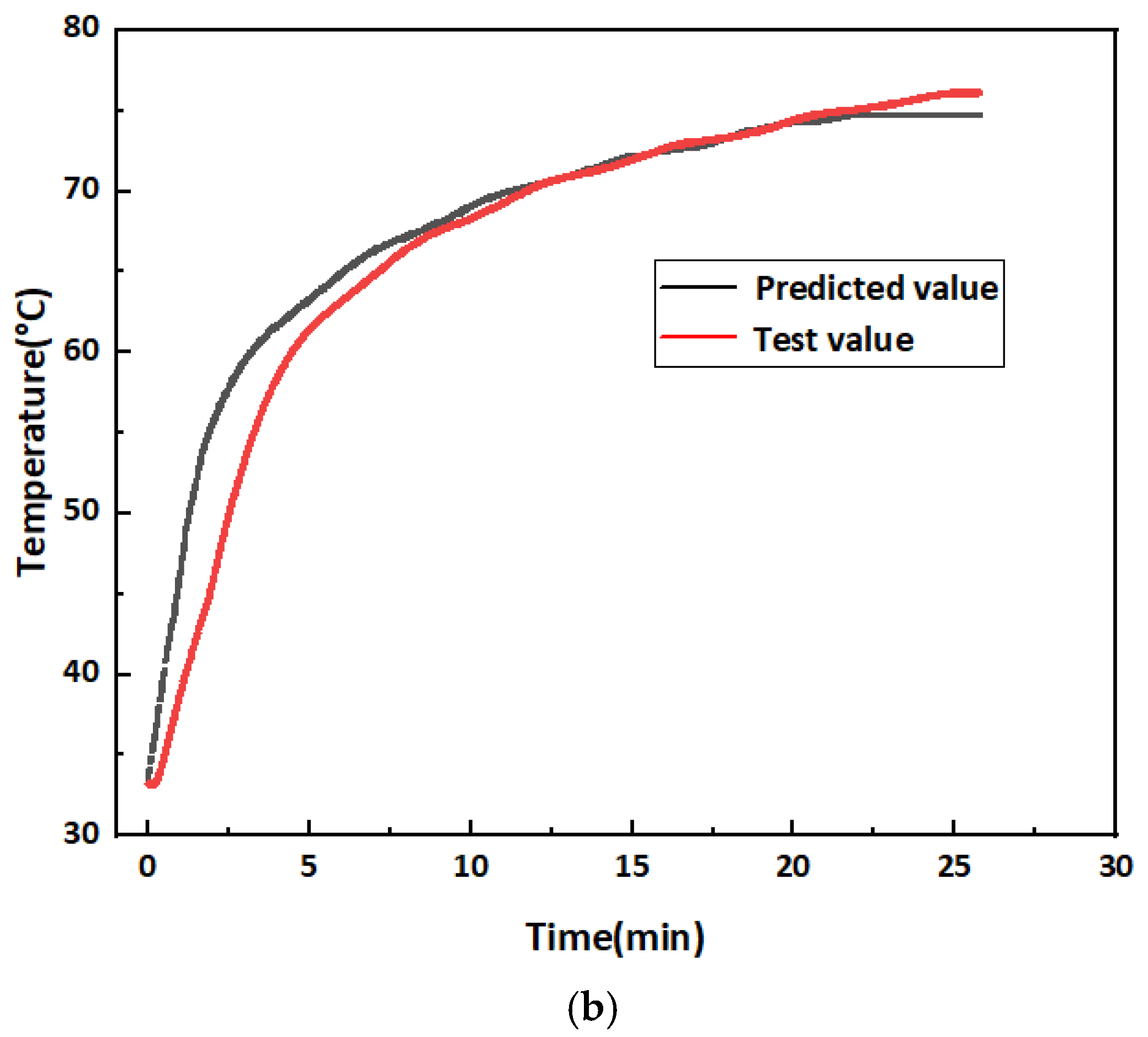
5.1. Validation
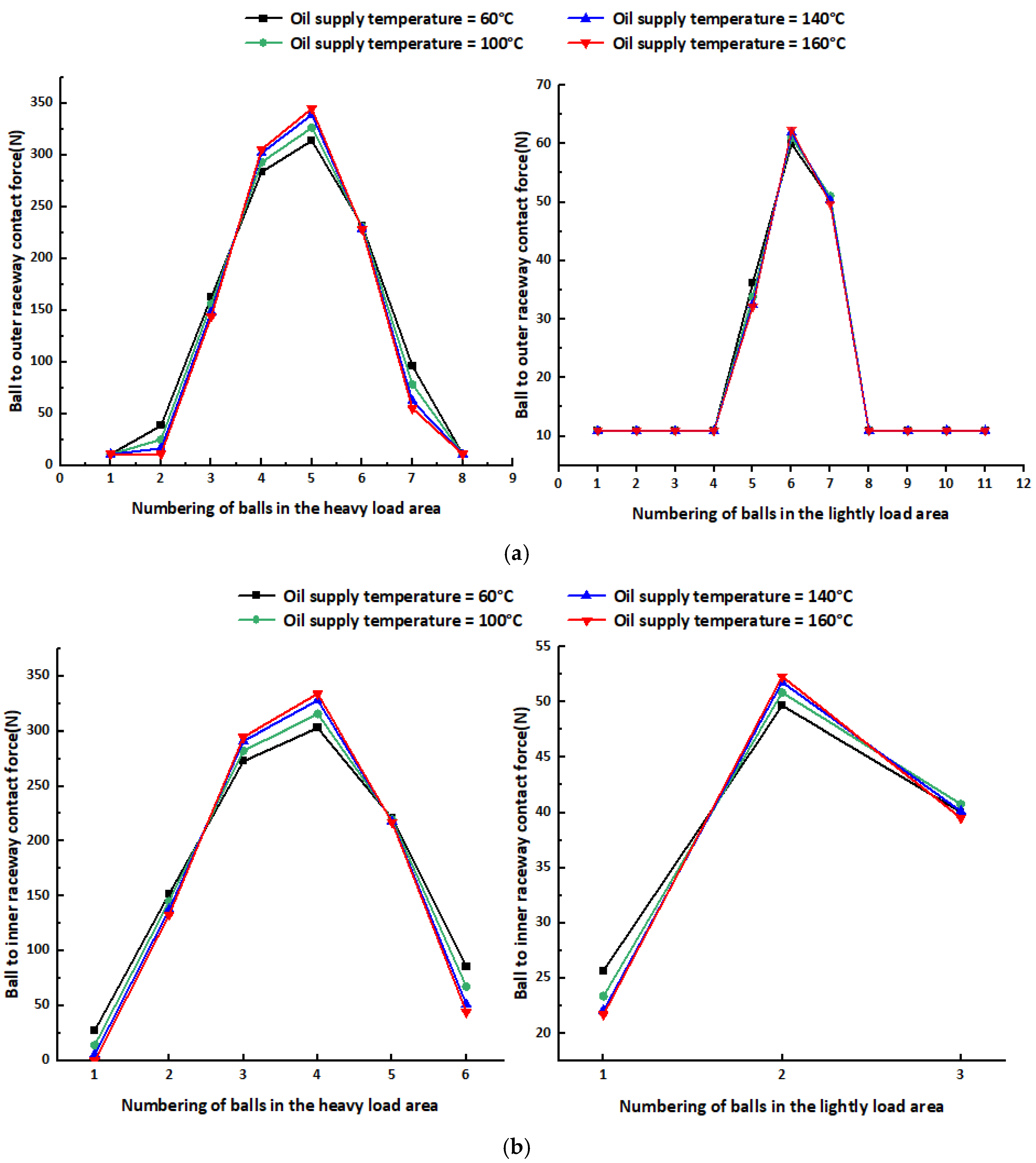
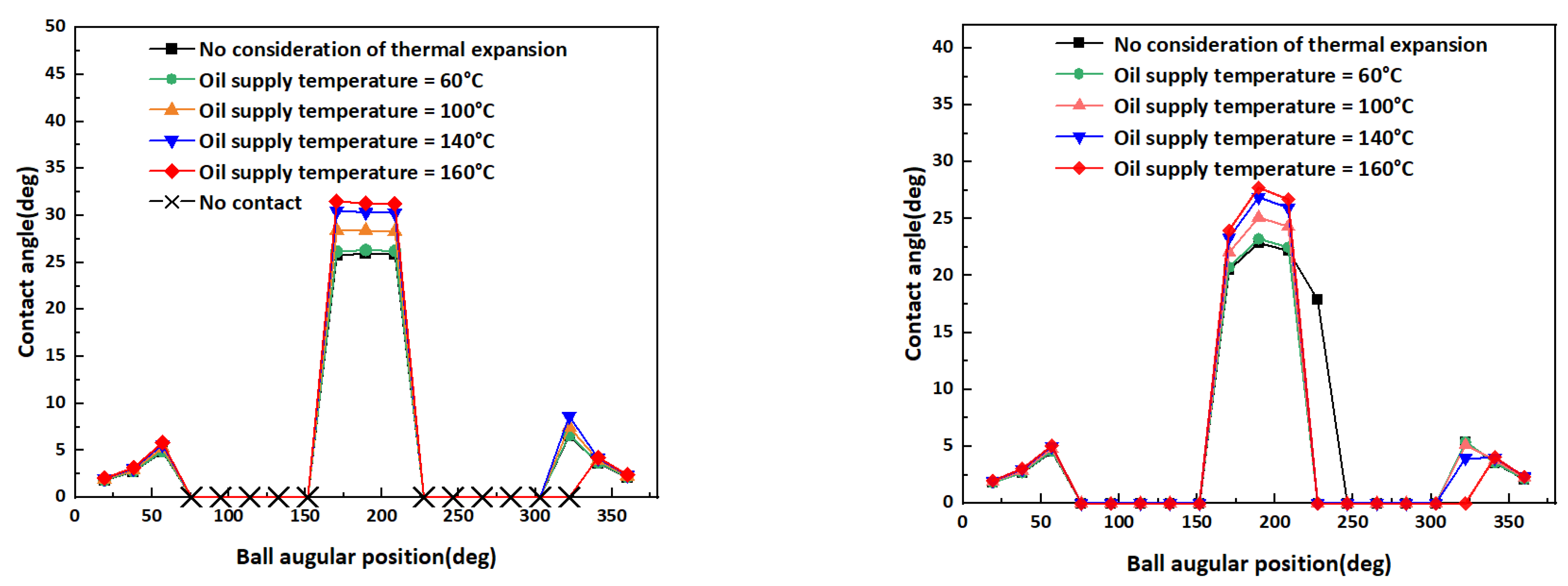
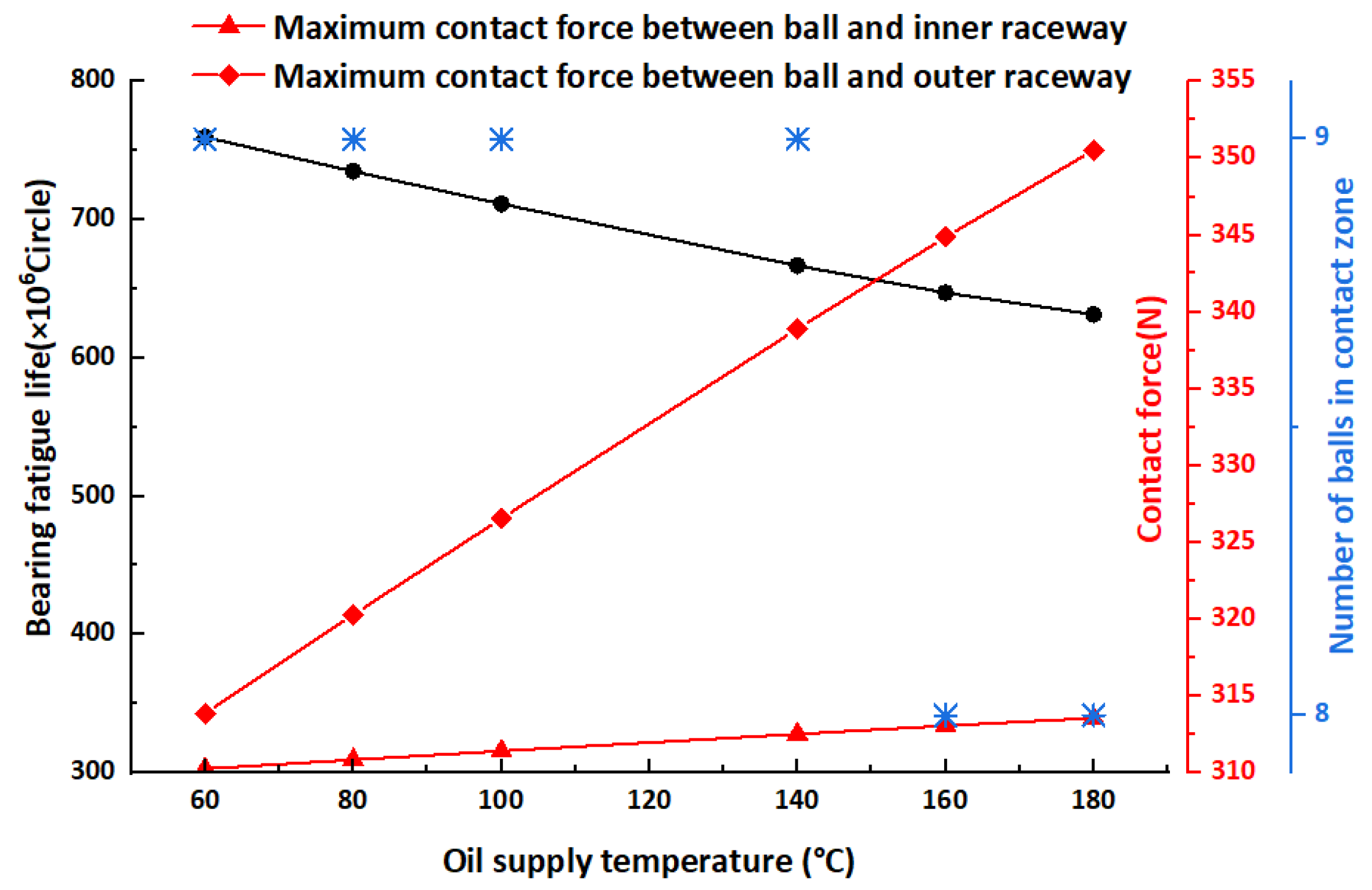
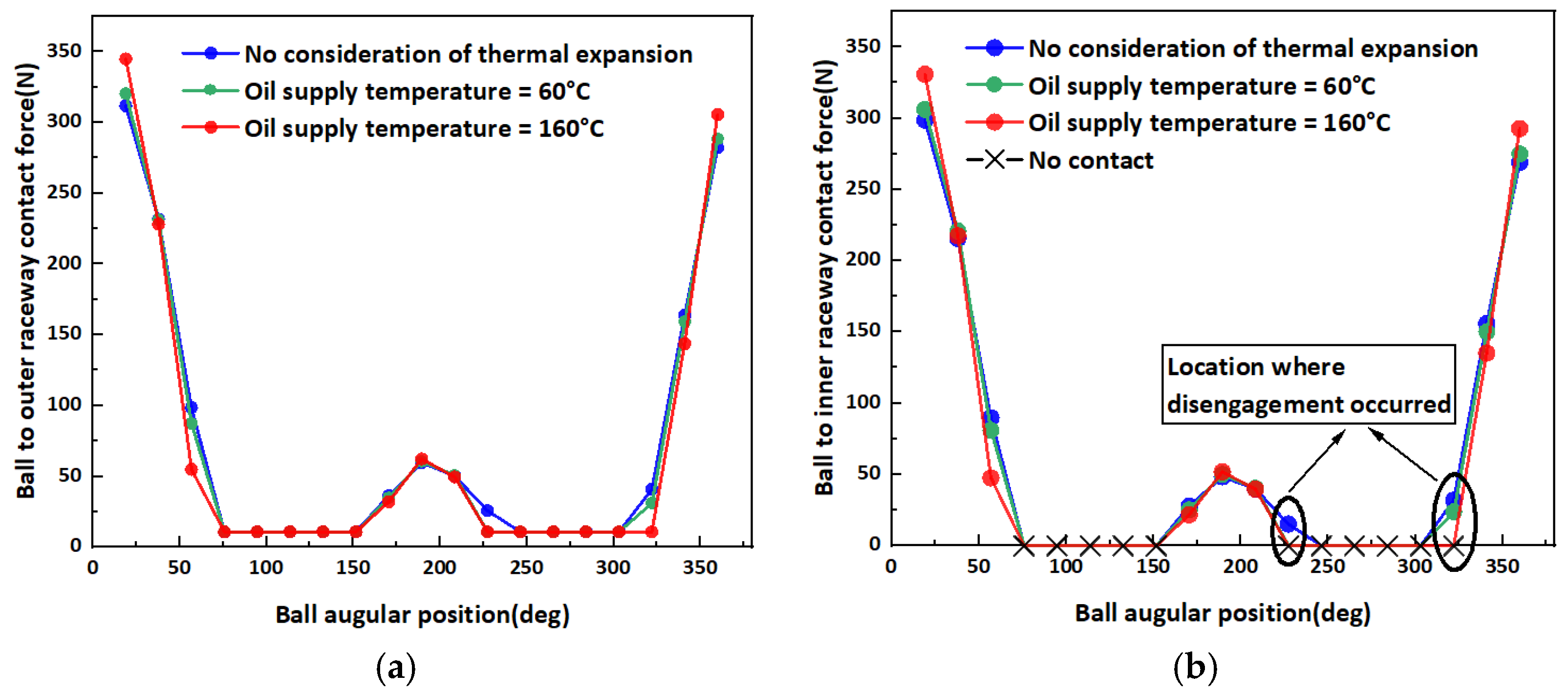
5.2. Effect of Temperature on Contact Characteristics
5.3. Effect of Temperature on Theoretical Fatigue Life
6. Conclusions
- (1)
- Under operating conditions of 12,000 rpm, 900 N radial force, and 100 N axial force, the thermal effect of a 100 °C temperature difference increases the maximum contact force by 8% and reduces the theoretical fatigue life by 12%, which cannot be taken into account in purely mechanical analysis.
- (2)
- Under the action of a strong asymmetric load, the temperature rise will tend to reduce the number of balls in the contact area of the inner raceway.
- (3)
- The temperature rise tends to concentrate the load distribution, which may be one of the reasons for the reduction in fatigue life.
Author Contributions
Funding
Institutional Review Board Statement
Informed Consent Statement
Data Availability Statement
Conflicts of Interest
References
- Yan, K.; Yan, B.; Wang, Y.; Hong, J.; Zhang, J. Study on thermal induced preload of ball bearing with temperature compensation based on state observer approach. Int. J. Adv. Manuf. Technol. 2018, 94, 3029–3040. [Google Scholar] [CrossRef]
- Palmgren, A. Ball and Roller Bearing Engineering; SKF Industries Inc.: Philadelphia, PA, USA, 1959. [Google Scholar]
- Harris, T.A.; Kotzalas, M.N. Advanced Concepts of Bearing Technology: Rolling Bearing Analysis; CRC Press: London, UK, 2006. [Google Scholar]
- Li, Z.; Guan, X.; Zhong, R.; Wang, Q. Analysis of Dynamic Characteristics of Angle Contact Bearings with Combined Load. J. Mech. Eng. 2020, 56, 116–125. [Google Scholar]
- Zhang, J.; Fang, B.; Hong, J.; Zhu, Y. Effect of preload on ball-raceway contact state and fatigue life of angular contact ball bearing. Tribol. Int. 2017, 114, 365–372. [Google Scholar] [CrossRef]
- Zhang, J.; Fang, B.; Zhu, Y.; Yan, K.; Hong, J. Investigation of the Load Distribution and Stiffness Characteristic of Ball Bearing under Ball-raceway Separation Condition. J. Mech. Eng. 2020, 56, 73–83. [Google Scholar]
- Zhang, Q.-Q.; Zhang, C. Thermal Characteristics Analysis and Test of High-speed Angle Contact Ball Bearing for Grease Lubrication. Sci. Technol. Eng. 2021, 21, 2286–2292. [Google Scholar]
- Zhang, C.; Tian, J.; Guo, D.; Niu, Q. Thermal characteristics of grease lubricated high-speed angular contact ball bearings with thermal deformation. J. Tsinghua Univ. (Sci. Technol.) 2022, 62, 482–492. [Google Scholar]
- Yu, J.; Liu, Z.; Shao, J.; He, L.; Yuan, W. Dynamic property of spindle bearing considering the effect of thermal deformation. J. Aerosp. Power 2018, 33, 477–486. [Google Scholar]
- Yan, K.; Hong, J.; Zhang, J.H.; Mi, W.; Wu, W. Thermal-deformation coupling in thermal network for transient analysis of spindle-bearing system. Int. J. Therm. Sci. 2016, 104, 1–12. [Google Scholar] [CrossRef]
- Zheng, D.X.; Chen, W.F.; Li, M.M. An optimized thermal network model to estimate thermal performances on a pair of angular contact ball bearings under oil-air lubrication. Appl. Therm. Eng. 2018, 131, 328–339. [Google Scholar]
- Zheng, D.X.; Chen, W.F. Effect of structure and assembly constraints on temperature of high-speed angular contact ball bearings with thermal network method. Mech. Syst. Signal Process. 2020, 145, 106929. [Google Scholar] [CrossRef]
- Liu, Y.; Ma, Y.X.; Meng, Q.Y.; Xin, X.-C.; Ming, S.-S. Improved thermal resistance network model of motorized spindle system considering temperature variation of cooling system. Adv. Manuf. 2018, 6, 384–400. [Google Scholar] [CrossRef] [Green Version]
- Than, V.T.; Huang, J.H. Nonlinear thermal effects on high-speed spindle bearings subjected to preload. Tribol. Int. 2016, 96, 361–372. [Google Scholar] [CrossRef]
- Xia, Z.X.; Wu, Y.H.; Ma, T.B.; Bao, Z.; Tian, J.; Gao, L.; Sun, J.; Li, S. Experimental study on adaptability of full ceramic ball bearings under extreme conditions of cryogenics and heavy loads. Tribol. Int. 2022, 175, 107849. [Google Scholar] [CrossRef]
- Wang, Y.B.; Yan, C.F.; Lu, Z.Y.; Wu, L. Effect of thermal elastohydrodynamic lubrication on vibration characteristics of ball bearing with local defect. Proc. Inst. Mech. Eng. Part K-J. Multi-Body Dyn. 2022, 236, 488–500. [Google Scholar] [CrossRef]
- Cao, Y.; Altintas, Y. A general method for the modeling of spindle-bearing systems. J. Mech. Des. 2004, 126, 1089–1104. [Google Scholar] [CrossRef]
- Ding, C.; Zhou, F.; Zhu, J.; Zhang, L. Raceway control assumption and the determination of rolling element attitude angle. Chin. J. Mech. Eng. 2001, 37, 58–61. [Google Scholar] [CrossRef]
- Deng, S.; Hua, X.; Zhang, W. Analysis on friction torque fluctuation of angular contact ball bearing in gyro motor. J. Aerosp. Power 2018, 33, 1713–1724. [Google Scholar]
- Takabi, J.; Khonsari, M.M. Experimental testing and thermal analysis of ball bearings. Tribol. Int. 2013, 60, 93–103. [Google Scholar] [CrossRef]
- Crecelius, W.J.; Pirvics, J. Computer Program Operation Manual on SHABERTH-A Computer Program for the Analysis of the Steady State and Transient Thermal Performance of Shaft-Bearing Systems; A189240; Engineering and Research Center of SKF Industries: King of Prussia, PA, USA, 1976. [Google Scholar]


| Deformation Components | Calculation Formula |
|---|---|
| Thermal expansion of the ball | εb = ∂b∙∆Tb∙Dw/2 |
| Radial heat deformation of the inner ring considering the thermal effect of the shaft and inner ring | εir = ∂i∙∆Ti∙di + [∂s∙∆Ts∙(1 + υs) − ∂i∙∆Ti] di2/dig |
| Thermal expansion of the outer ring considering the outer ring limit of the bearing housing | εor = ∂h∙∆Th∙(1 + υh)dog |
| Materials | Density (kg/m3) | Coefficient of Thermal Expansion (μm/(°C)) | Young’s Elastic Modulus (GPa) | Poisson’s Ratio | Thermal Conductivity (W/(m ∙ K)) | Specific Heat Capacity (J/(kg∙°C)) |
|---|---|---|---|---|---|---|
| 45#steel | 7850 | 11.6 | 206 | 0.26 | 50.2 | 486 |
| GCr15 | 7810 | 12.5 | 219 | 0.3 | 40.1 | 450 |
| 40Cr | 7900 | 15.5 | 211 | 0.28 | 66.6 | 460 |
| Models | Applications | Comment |
|---|---|---|
| Natural convection between the bearing housing and the air [11] | Re—Reynolds number Pr—Prandtl number N—Spindle speed | |
| Natural convection between housing, end caps, etc., and ambient air [11] | Lg—Thickness of the void space between the two contact surfaces | |
| hring—Outer ring thickness | ||
| Forced convection between rotating surfaces and air [20] | So-z—Contact surface area between outer ring and bearing housing | |
| Forced convection between the sides of the rotating surface and the air [11] | hgap—Initial clearance Tring—Outer ring temperature Th—Bearing housing temperature | |
| Average convective heat transfer coefficient between the lubricant and the original components in the bearing [21] | rh—Inner radius of bearing housing hcont—Contact conductivity e—Elliptical eccentricity | |
| Thermal contact resistance between ball and raceway [13] | Ai-s—Contact area between shaft and inner ring Ee—First class elliptic integrals | |
| Thermal contact resistance between the shaft and the inner ring of the bearing [11] | Ar*—Dimensionless actual contact area 𝜐oil—Lubricant kinematic viscosity | |
| Thermal contact resistance between outer ring and bearing housing [14] | λs—Thermal conductivity of spindle materials |
| Parameter Type | Value |
|---|---|
| Pitch diameter of the bearing dm/mm | 54.007 |
| Number of balls | 19 |
| Ball diameter Dw/mm | 7.144 |
| Contact angle | 15 |
| Radius of curvature of the inner raceway ri/mm | 4 |
| Radius of curvature of the outer raceway ro/mm | 3.79 |
| Inner raceway diameter dig/mm | 46.838 |
| Outer raceway diameter dog/mm | 61.176 |
Publisher’s Note: MDPI stays neutral with regard to jurisdictional claims in published maps and institutional affiliations. |
© 2022 by the authors. Licensee MDPI, Basel, Switzerland. This article is an open access article distributed under the terms and conditions of the Creative Commons Attribution (CC BY) license (https://creativecommons.org/licenses/by/4.0/).
Share and Cite
Dong, Y.; Chen, F.; Qiu, M.; Wang, H.; Yang, C. Study of the Contact Characteristics of Machine Tool Spindle Bearings under Strong Asymmetric Loads and High-Temperature Lubrication Oil. Lubricants 2022, 10, 264. https://doi.org/10.3390/lubricants10100264
Dong Y, Chen F, Qiu M, Wang H, Yang C. Study of the Contact Characteristics of Machine Tool Spindle Bearings under Strong Asymmetric Loads and High-Temperature Lubrication Oil. Lubricants. 2022; 10(10):264. https://doi.org/10.3390/lubricants10100264
Chicago/Turabian StyleDong, Yanfang, Feifan Chen, Ming Qiu, Huijie Wang, and Chuanmeng Yang. 2022. "Study of the Contact Characteristics of Machine Tool Spindle Bearings under Strong Asymmetric Loads and High-Temperature Lubrication Oil" Lubricants 10, no. 10: 264. https://doi.org/10.3390/lubricants10100264
APA StyleDong, Y., Chen, F., Qiu, M., Wang, H., & Yang, C. (2022). Study of the Contact Characteristics of Machine Tool Spindle Bearings under Strong Asymmetric Loads and High-Temperature Lubrication Oil. Lubricants, 10(10), 264. https://doi.org/10.3390/lubricants10100264