Concept Paper

Modulated Differential Wavefront Sensing: Alignment Scheme for Beams with Large Higher Order Mode Content

1
Max Planck Institute for Gravitational Physics, University of Hannover, D-30167 Hannover, Germany
2
Inter-University Centre for Astronomy and Astrophysics, Post Bag 4, Ganeshkhind Pune 411007, India
3
School of Physics and Astronomy, Cardiff University, The Parade, Cardiff CF24 3AA, UK
4
SUPA, School of Physics and Astronomy, The University of Glasgow, Glasgow G12 8QQ, UK
*
Author to whom correspondence should be addressed.
These authors are all former group member at GEO 600.
Galaxies 2020, 8(4), 81; https://doi.org/10.3390/galaxies8040081
Submission received: 23 October 2020 / Revised: 25 November 2020 / Accepted: 27 November 2020 / Published: 3 December 2020
(This article belongs to the Special Issue Gravitational Wave Detectors)

Abstract

:
Modulated differential wavefront sensing (MDWS) is an alignment control scheme in the regime of beams with strong higher order transversal modes (HOMs). It is based on the differential wavefront sensing (DWS) technique. MDWS represents a significant upgrade over conventional techniques used in the presence of high HOM content as it allows for higher control bandwidths while eliminating the need of auxiliary alignment modulations, that otherwise cause loss of applied squeezing. The output port of gravitational wave (GW) interferometers (IFO) is one such place where a lot of HOMs are present. These are filtered out by a cavity called the output mode cleaner (OMC), whose alignment gets challenging due to the presence of HOMs. In this paper, we present the first demonstration of the MDWS scheme for aligning the fundamental mode from the IFO to the OMC at the gravitational wave detector-GEO 600.
Keywords:
HOMs; OMC; DWS; alignment; IFO; GEO 600

1. Introduction

GEO 600 is a Dual Recycled Michelson Interferometer (DRMI) [1], which operates with a small dark fringe offset (DFO), which allows a certain amount of carrier light to leave the interferometer (IFO) at the output port (Figure 1). In this operating state, the Michelson interferometer (MI) as a whole behaves like a mirror and reflects the injected laser light almost completely. The power recycling mirror (MPR) recycles this light by forming the power recycling resonator (PRC) with the rest of the IFO (Figure 2). The carrier light is resonantly amplified by the PRC, with a gain factor of about 1000. The signal recycling mirror (MSR) at the output port forms another cavity, called the signal recycling resonator (SRC). This cavity resonantly enhances the gravitational wave signal sidebands (GW) exiting towards the output by reflecting them back into the IFO. Due to imperfections in the optics, their misalignment and thermal effects, especially in the beam splitter, there is a significant amount of light present as higher order transversal modes (HOMs) [2] at the output port. In the standard operational operating state of the detector, the total light power at the IFO output is about 36 mW, of which the carrier component T E M 00 is about 6 mW and each of the Michelson control sidebands (MI SBs) at 14.9 MHz is about 1 mW. The rest is due to HOMs.
HOMs and SBs contribute to (shot) noise, but do not carry a useful GW signal. Therefore, an Output Mode Cleaner (OMC) (see Figure 2) is provided which is in resonance with the carrier and attenuates the HOMs and SBs to reduce their contribution to shot noise in the GW frequency band by a factor of 10 [4,5]. The technique used to read out the GW channel is called DC readout [6], which creates a beat between the carrier and the GW SBs when transmitted through the OMC. For good detector sensitivity, the carrier must therefore be well aligned with the OMC.
All interferometric GW detectors have used OMC alignment techniques based on the dithering of the quantity of interest [7], which in our case are alignment degrees of the beam incident on the OMC. In the case of GEO 600, for example, this would be done by modulating the beam steering optics (BDO) (see Figure 2), i.e., BDO1 and BDO3 in rotation and tilt at these dither frequencies: BDO1R–17 Hz, BDO1T–11 Hz, BDO3R–3.5 Hz, BDO3T–14 Hz.
If the intensity of the beam in transmission of the OMC is given as I ( θ ), where the angle ( θ ) is the input beam angle, then a modulation injected into θ can be expressed as:
θ = θ 0 + m sin ω t
where m ≪ 1 is the modulation index and ω is the dither frequency. Then the resulting intensity fluctuation will look like:
I θ = I ( θ 0 + m sin ω t ) I ( θ 0 ) + I θ ( θ 0 ) m sin ω t +
The amplitude of the modulation signal at ω is proportional to the partial derivative term and can be extracted by demodulation. Since the cavity transfer function is symmetric around optimal alignment, the derivative will disappear there, indicating the desired alignment for that degree of freedom (DoF). If this is done for all four DoFs then four feedback loops can be employed to keep the incoming beam aligned to the cavity’s eigenmode. This is the principle of dither locking. The extension of dither locking is the beacon dither technique used at GEO 600, where the optical mode in which a GW signal would be present is marked by a “beacon” signal by differentially actuating on the MI end test masses at 3.17 kHz. The beacon dither scheme aims to maximize the transmission of the beacon signal as described in [7,8]. This scheme is robust against small alignment drifts and is sufficient for the daily operation of the detector, but has certain limitations.
First, the control bandwidth achieved is less than 20 mHz [5], which is not sufficient to suppress the misalignment caused by the MI suspension resonances around 1 Hz. Second, the process of dithering introduces additional jitter of the beam incident on the OMC, which has been shown to cause a 0.2 dB loss in squeezing at the 5.5 dB level [3,9]. To get around these limitations, we have tested a new scheme called Modulated Differential Wavefront Sensing (MDWS), which allows for a higher control bandwidth and eliminates the need for dithering. It was first proposed and a preliminary demonstration was shown in [10].

2. Differential Wavefront Sensing Technique

As already mentioned, MDWS is an extension of the well known DWS technique, which can measure the relative misalignment between two wavefronts. When the longitudinal degree of a cavity is locked, for example with the Pound–Drever–Hall (PDH) technique [11] (or any other), the relative misalignment between the axis of the incoming beam and the cavity eigenmode axis can also be sensed by the same technique of using phase modulated sidebands, also known as heterodyne sensing.
Any misalignment (beam tilt or beam translation) of a Gaussian beam couples light to its first higher order mode. This creates a spatial phase gradient across the beat field of the carrier and the promptly reflected sidebands. The DWS method uses this spatial information to probe angular misalignment. This concept was first proposed by [12] and first experimentally demonstrated by [13,14].
To make the equations generic to longitudinal and angular misalignment, the notation of [13] is being used where the modulated and matched field can be described as
E 1 = A 1 U 0 e j ( ω t + m ( t ) + Φ ) , w h e r e
m(t) is the phase modulation and Φ is a constant phase difference between the fundamental modes of E 1 and a mismatched field, E 2 , described as
E 2 = A 2 U 0 e j ω t + A 2 U 1 e j ( ω t + ϕ ( z ) + α n ) , w h e r e
ϕ ( z ) is the Gouy phase shift associated with the first order mode of a Gaussian beam and α n is the phase shift due to the misalignment. For beam tilt, α 0 = π 2 and for beam translation, α 1 = 0.
Also, U 0 , U 1 , U 2 are the first three higher order modes of a Gaussian beam.
The total light field incident on a photo detector is given by E t = E 1 + E 2 and the signal is given by
E T = E t E t * .
The resulting field has terms due to the superposition of the fundamental modes of the two fields, which are proportional to A 1 A 2 U 0 2 c o s ( m + Φ ) . Taking the integral and demodulating at m gives the PDH error signal. However, the terms interesting for angular mismatches are the coefficients of E 0 E 1 and when the modulation m is small,
E T U 0 U 1 [ m sin ( ϕ α n ) ] .
This approximation is valid only when Φ = 0 , i.e., when the length of the cavity is held constant and the second order modes, arising due to mismatches in the waist size and the position of the two interfering beams, have also been corrected. Using a quadrant photodiode, the difference in intensity of its two halves along the x-axis can be expressed as
I x = 0 E T d x 0 E T d x .
I x m sin ϕ cos α n m cos ϕ sin α n .
The misalignment can be obtained by suitable values for α n , ϕ and demodulation with m(t). Hence, two quadrant photodetectors placed at z = 0 (near sensor) and z (far sensor) serve as an orthogonal sensing basis for the two kinds of misalignment. If this is also done for the y plane, the four misalignment signals can be obtained.

3. Modulated Differential Wavefront Sensing

The equations developed for DWS can now be extended to explain the MDWS scheme. As explained in Section 1, the light fields at the GEO 600 output port consists of a small T E M 00 component at the carrier frequency, control sidebands and mostly HOMs at the carrier frequency. This means that the field reflected by the OMC is also contaminated and so a small misalignment of the carrier w.r.t to MI SBs, that serve as reference for alignment, cannot be sensed by a DWS setup. So, an additional modulation is used to mark the OMC’s internal mode. The sensing procedure remains the same.
The rationale of two modulations is as follows:
(i.)
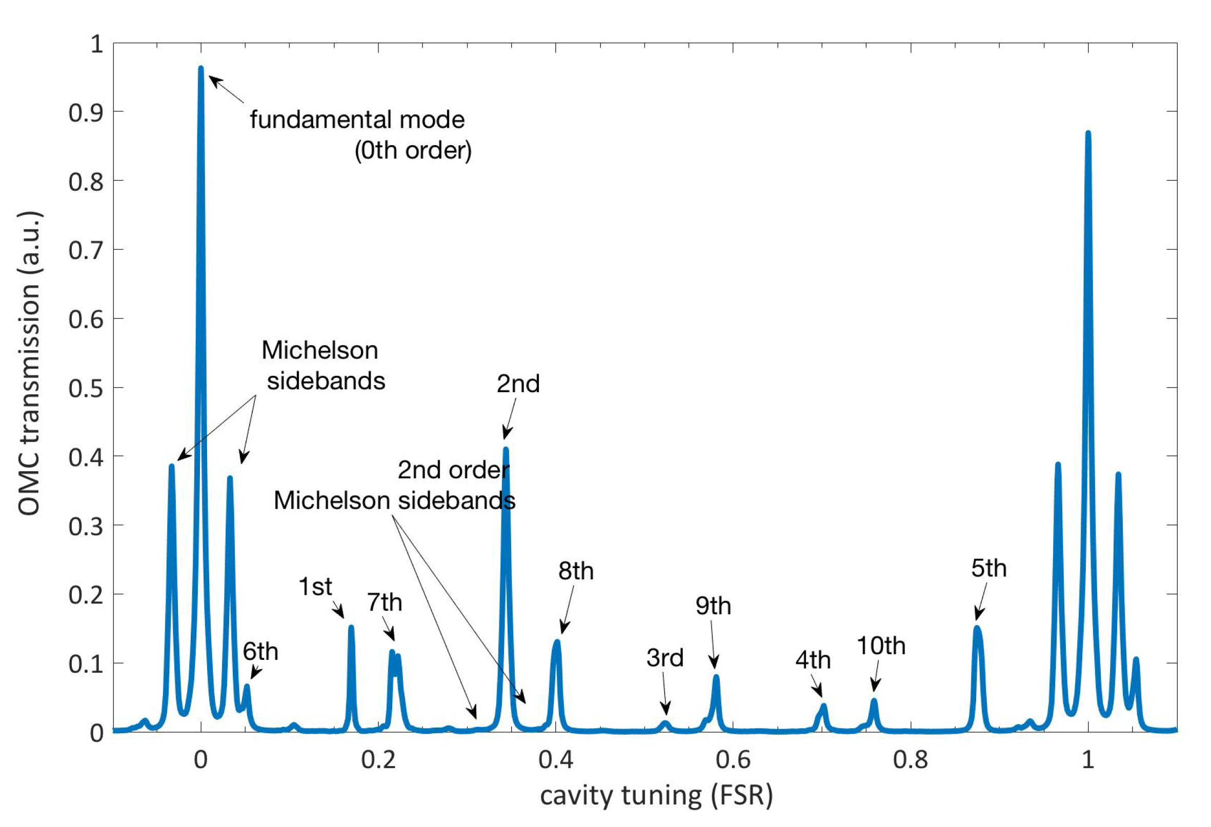
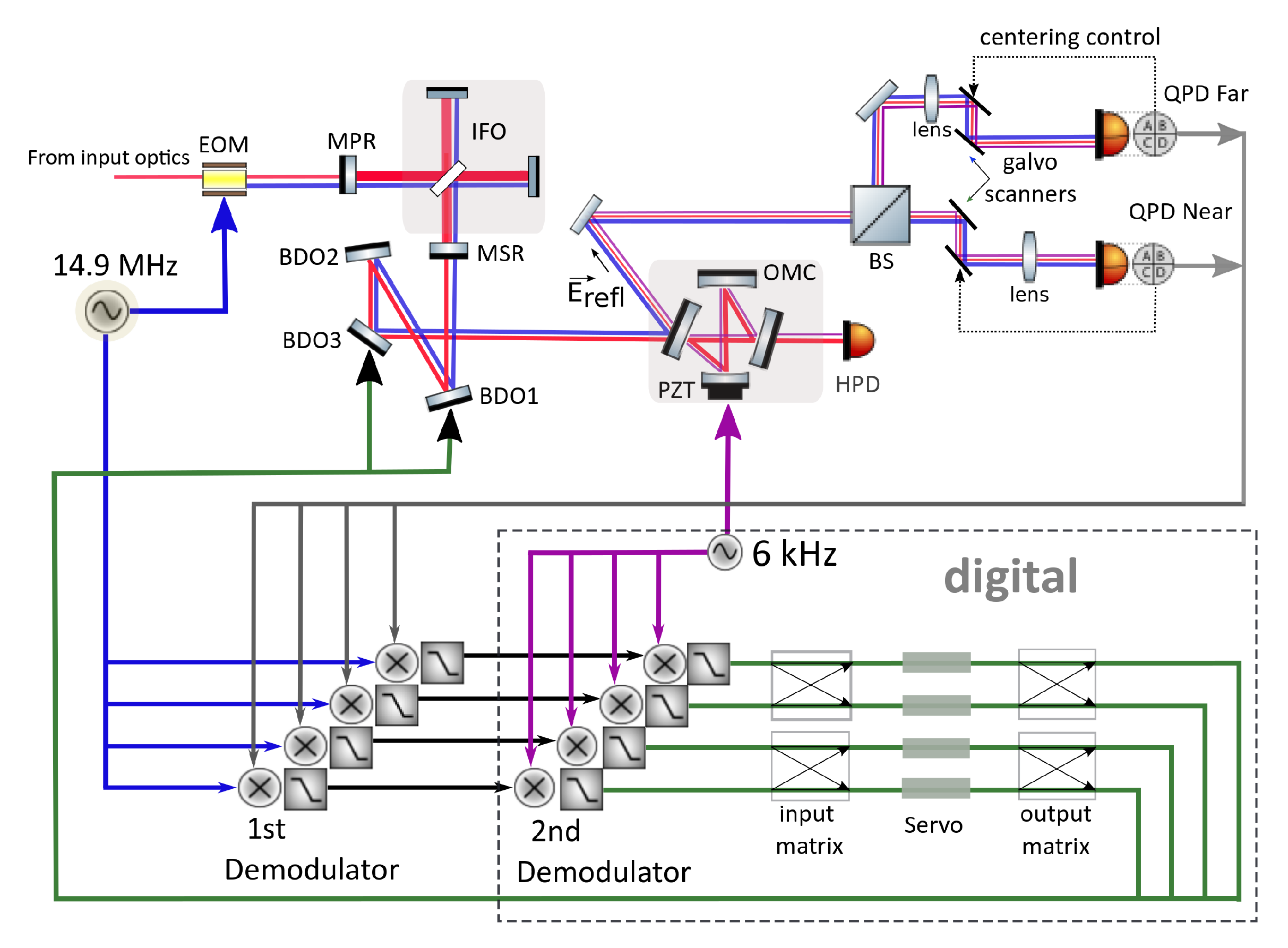
The first is a phase modulation at 14.9 MHz, referred to as the MI SBs ( f M I ), which is done to the MI input beam (see Figure 2). The MI SBs are resonant in the MI along with the carrier, but with a smaller power enhancement factor. Hence, they are predominantly in the T E M 00 mode and serve as a good approximation of the fundamental GW carrying mode [10]. Also, they are promptly reflected by the OMC and can be found in the OMC reflected field.
(ii.)
The second modulation at 6 kHz ( f O M C ) is done via the PZT attached to one of the mirrors of the OMC. This frequency f O M C , modulating the carrier inside the OMC, appears as phase modulation sidebands leaking out through the reflection port of the OMC, thus marking its eigenmode. There is also a component due to the prompt reflection of the carrier at the OMC reflected port, but this does not contain information about the cavity mode. It should be mentioned here that f O M C is an already existing modulation used for the longitudinal control of the OMC by the dither locking technique. Therefore, no additional auxiliary modulation is required for MDWS.
In this case, the error signals can still be obtained using the difference of the modulated currents from the quadrant photodiode but now the signal will be present at the beat frequency of f M I f O M C . Equation (7) gets modified as
I x ( m 1 m 2 ) sin ϕ c o s α n ( m 1 m 2 ) cos ϕ sin α n
where m 1 = f M I and m 2 = f O M C .
The signal of interest is obtained by a two-step demodulation. The first demodulation at f M I is done in the analog domain, giving the DWS signal. This signal is acquired by the digital system [15] and then demodulated at f O M C , giving the MDWS error signal.
To obtain reliable MDWS alignment signals, the spot of the interfering light fields has to be kept centred on the QPDs based on the beat signal between the upper and lower MI SBs. This is called the 2f sensing technique. The usual method for spot centering is based on ensuring that the DC power is symmetrically distributed on the sensors. However, this method does not work at the detector output because the carrier is strongly contaminated with HOMs, which make the DC method unreliable. Instead, the distribution of the beat of the MI SBs at twice the frequency is used, giving the light power on the four quadrants at 2 f M I [16]. A feedback loop actuating on mirrors attached to galvanometers (labelled “galvo scanners” in Figure 2) that direct the beam on the QPDs is used for centering.

4. Measurements and Results

We demonstrated the proof of principle test for MDWS and obtained control bandwidth of up to 2 Hz (Figure 3). A limitation of the system is the 8° Gouy phase separation between the actuating mirrors, BDO1 and BDO3, which is only a particular limitation of the current GEO 600 setup. This means that for spanning the full DoF space the actuators have to make excessive movement that can lead to coupling between the loops. To ensure that the actuation stays well decoupled a gain hierarchy is maintained such that BDO1 loops mainly compensate for the misalignment while BDO3 acts on residual misalignment.
An important quantity to estimate is the noise contribution of a subsystem to the GW channel which can also be called as the GW strain ( h ) channel. This can be measured through noise projections [17] from the respective channel to h . Figure 4 shows the coupling of noise through the MDWS feedback to h where the loops with higher gain contribute more noise.
It was observed that the MDWS error signals get random alignment offsets when the IFO loses lock and relocks for which hand-tuning of offsets was necessary. A suspected reason behind this is the spot centring electronics that causes spurious DC offsets and leads to drift in the alignment signals.

5. Conclusions

This work shows the successful implementation of the MDWS alignment scheme for the OMC in GEO 600—the first implementation of this technique in a gravitational wave detector. We achieved a control bandwidth of 2 Hz, about 100 times better than the conventional beacon dither scheme that also surpasses the MI suspension resonances around 1 Hz. This can be further extended by better actuator separation and reduction of HOMs at the output port as already mentioned. To improve the system further, we have developed new electronic modules for spot centering with better RF shielding that will heavily reduce any coupling related to imperfect electronics. As a long term improvement, the spot centering servo is being migrated to the digital system.
In summary, MDWS is a promising scheme in the presence of beams with high HOM content, which is currently true for the output port of all GW detectors. Getting rid of dithers for alignment control of the OMC is another advantage that will reduce losses in the application of squeezing, which will be routinely used in the next generation of GW detectors.

Author Contributions

Conceptualization, H.G., J.L. (Jonathan Leong), H.L., K.S., K.D.; Investigation, A.B., M.P., J.L. (Jonathan Leong), E.S., S.D., J.L. (James Lough), C.A., M.B., M.W., V.K. and H.W.; writing—review and editing, all authors. All authors have read and agreed to the published version of the manuscript.

Funding

This research received no external funding.

Acknowledgments

The authors thank the GEO collaboration for the development and construction of GEO 600. We are also grateful for support from the Science and Technology Facilities Council (STFC), the University of Glasgow in the UK, the Max Planck Society, the Bundesministerium für Bildung und Forschung (BMBF), the Volkswagen Stiftung, the cluster of excellence QUEST (Centre for Quantum Engineering and Space-Time Research), the international Max Planck Research School (IMPRS), and the State of Niedersachsen in Germany.

Conflicts of Interest

The authors declare no conflict of interest.

References

  1. Grote, H.; Freise, A.; Malec, M.; Heinzel, G.; Willke, B.; Lück, H.; Strain, K.A.; Hough, J.; Danzmann, K. Dual recycling for GEO 600. Class. Quantum Gravity 2004, 21, S473. [Google Scholar] [CrossRef]
  2. Wittel, H.; Lück, H.; Affeldt, C.; Dooley, K.L.; Grote, H.; Leong, J.R.; Prijatelj, M.; Schreiber, E.; Slutsky, J.; Strain, K.; et al. Thermal Correction of Astigmatism in the Gravitational Wave Observatory GEO 600. Class. Quantum Gravity 2014, 31, 065008. [Google Scholar] [CrossRef] [Green Version]
  3. Schreiber, E. Gravitational-Wave Detection beyond the Quantum Shot-Noise Limit. Ph.D. Thesis, Gottfried Wilhelm Leibniz Universität, Hannover, Germany, 2017. [Google Scholar]
  4. Wittel, H. Active and Passive Reduction of High Order Modes in the Gravitational Wave Detector GEO 600. Ph.D. Thesis, Gottfried Wilhelm Leibniz Universität, Hannover, Germany, 2015. [Google Scholar]
  5. Prijatelj, M. Gravitational Wave Detection with Refined Light. Ph.D. Thesis, Gottfried Wilhelm Leibniz Universität, Hannover, Germany, 2012. [Google Scholar]
  6. Hild, S.; Grote, H.; Degallaix, J.; Chelkowski, S.; Danzmann, K.; Freise, A.; Hewitson, M.; Hough, J.; Lück, H.; Prijatelj, M.; et al. DC-readout of a signal-recycled gravitational wave detector. Class. Quantum Gravity 2008, 26, 5. [Google Scholar] [CrossRef]
  7. Smith, N. Techniques for Improving the Readout Sensitivity of Gravitational Wave Antennae. Ph.D. Thesis, Massachusetts Institute of Technology, Cambridge, MA, USA, 2012. [Google Scholar]
  8. Prijatelj, M.; Grote, H.; Degallaix, J.; Hewitson, M.; Hild, S.; Affeldt, C.; Freise, A.; Leong, J.; Lück, H.; Strain, K.A.; et al. Control and automatic alignment of the output mode cleaner of GEO 600. J. Phys. Conf. Ser. 2010, 228, 012014. [Google Scholar] [CrossRef]
  9. Lough, J.; Schreiber, E.; Bergamin, F.; Grote, H.; Mehmet, M.; Vahlbruch, H.; Affeldt, C.; Brinkmann, M.; Bisht, A.; Kringel, V.; et al. First Demonstration of 6 dB Quantum Noise Reduction in a Kilometer Scale Gravitational Wave Observatory. Available online: https://arxiv.org/abs/2005.10292v1 (accessed on 20 May 2020).
  10. Affeldt, C.; Danzmann, K.; Dooley, K.L.; Grote, H.; Hewitson, M.; Hild, S.; Hough, J.; Leong, J.; Lück, H.; Prijatelj, M.; et al. Advanced Techniques in GEO 600. Class. Quantum Gravity 2014, 31, 22. [Google Scholar] [CrossRef]
  11. Drever, R.W.P.; Hall, J.L.; Kowalski, F.V.; Hough, J.; Ford, G.M.; Munley, A.J.; Ward, H. Laser Phase and Frequency Stabilization Using an Optical Resonator. Appl. Phys. B 1983, 31, 97–105. [Google Scholar] [CrossRef]
  12. Anderson, D.Z. Alignment of resonant optical cavities. Appl. Opt. 1984, 23, 17. [Google Scholar] [CrossRef] [PubMed] [Green Version]
  13. Morrison, E.; Meers, B.J.; Robertson, D.I.; Ward, H. Automatic alignment of optical interferometers. Appl. Opt. 1994, 33, 5041–5049. [Google Scholar] [CrossRef] [PubMed]
  14. Morrison, E.; Meers, B.J.; Robertson, D.I.; Ward, H. Experimental demonstration of an automatic alignment system for optical interferometers. Appl. Opt. 1994, 33, 5037–5040. [Google Scholar] [CrossRef] [PubMed]
  15. Bork, R.; Aronsson, M.; Ivanov, A. aLIGO CDS Real-Time Code Generator (RCG V2.8), Application Developer’s Guide; LIGO-T080135-v9. 2013. Available online: https://dcc.ligo.org/LIGO-T080135/public (accessed on 20 May 2020).
  16. Grote, H.; The LIGO Scientific Collaboration. The GEO 600 status. Class. Quantum Gravity 2010, 27, 8. [Google Scholar] [CrossRef]
  17. Smith, J.R. Formulation of Instrument Noise Analysis Techniques and Their Use in the Commissioning of the Gravitational Wave Observatory, GEO 600. Ph.D. Thesis, Gottfried Wilhelm Leibniz Universität, Hannover, Germany, 2006. [Google Scholar]
Figure 1. A mode scan of the output mode cleaner (OMC) with dark fringe offset (DFO) (Figure taken from [3]) showing the higher order transversal mode (HOM) content of the interferometer (IFO) output beam.
Galaxies 08 00081 g001
Figure 2. Schematic of the Modulated differential wavefront sensing (MDWS) sensing and control scheme. The input optics have been ignored for simplicity. The Michelson interferometer (MI) sidebands (SBs), f M I , at 14.9 MHz are imprinted onto the carrier via the EOM before it enters the IFO. The OMC length modulation, f O M C , at 6 kHz marks the eigen mode of the OMC and is applied through the digital control system. The QPD signals are demodulated twice as shown to give the MDWS error signal which is used for actuation on the BDO1 and BDO3 mirror.
Galaxies 08 00081 g002
Figure 3. Amplitude spectra of the MDWS error signals at the near and far QPD for the horizontal (top) and vertical (bottom) plane. The loops in which more suppression is visible are at a higher gain.
Galaxies 08 00081 g003
Figure 4. The noise projection of the MDWS feedback signals to h. The rotation of the mirror about the horizontal axis is called tilt and about the vertical axis is called rot. Below 1 Hz, h is dominated by the feedback noise but reduces gradually for higher frequencies.
Galaxies 08 00081 g004
Publisher’s Note: MDPI stays neutral with regard to jurisdictional claims in published maps and institutional affiliations.

