Abstract
Optical aberrations represent a critical issue for gravitational wave interferometers, as they impact the stability and controllability of the experiment. In the next generation of detectors, the circulating power in the cavity arms is expected to increase by up to a factor of 20 compared to current ones. This significant increase makes the mitigation of power-dependent optical aberrations extremely challenging. In this paper, we describe the problem of absorption in the optics and its role in generating some of the most important wavefront distortions, along with the present compensation strategy. To meet the new stringent requirements, new technologies must be designed, and existing ones upgraded. We present a review of the strategies and concepts in the field of aberration control in gravitational wave detectors and discuss the challenges for future detectors like the high-power operation of the Einstein Telescope.
1. Introduction
Gravitational wave (GW) astronomy has significantly advanced our understanding of the universe, providing valuable insights into phenomena such as black holes and neutron star mergers. The evolution of GW interferometers reflects the remarkable trajectory of technological advancements and scientific breakthroughs. First-generation detectors, including the initial LIGO and Virgo facilities, demonstrate the feasibility of GW detection but lack the sensitivity required for actual observations. The advent of second-generation instruments, such as Advanced LIGO [1] and Advanced Virgo [2], mark a pivotal milestone, culminating in the first successful detection of GW in 2015 [3], followed by many other events [4,5,6,7,8]. Looking ahead, the Einstein Telescope (ET) [9,10], a third-generation detector, aims to build on these achievements, offering enhanced sensitivity and an expanded frequency range to observe more distant, faint, and diverse sources, including those from the early universe.
The ET, designed as an underground interferometer with 10–15 km-long arms, will operate across an extended frequency range through a dual-band approach. This innovative configuration features two distinct interferometers: a cryogenic low-frequency (ET-LF) system and a high-power high-frequency (ET-HF) one. The ET-HF, in particular, represents a significant technological challenge, with the circulating cavity power expected to reach approximately 3 MW [9]. Addressing these challenges will necessitate advances in core optics design and the effective mitigation of thermal effects.
2. Core Optics for Third-Generation GW Detectors
The core optics (CO) are all the large optics that compose interferometric GW detectors’ resonant cavities; we will focus the conversation on the mirror test masses (TMs) that form the arm cavities since these have the most stringent requirements. These components are critical to achieve the extreme sensitivity necessary for astrophysical observations. For third-generation instruments, the design of CO must overcome the unprecedented challenges posed by increased circulating laser power and stringent noise reduction requirements.
2.1. Current Mirror Technologies
Modern GW detectors rely on dielectric mirrors composed of a substrate coated with a reflective multilayer stack, known as Bragg reflectors (see Figure 1).
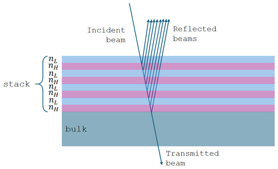
Figure 1.
Schematization of a Bragg reflector. The top (light blue and violet) layers represent the pairs of alternate low- and high-refractive index material. On every interface in the stack, a part of the incident beam is reflected. The intensity of the incident light beam decreases during its travel through the quarter-wave stack and at the same time the reflected light increases. This illustration is a simplified example; in reality, the number of alternating high- and low-refractive index pairs is significantly larger.
These coatings consist of alternating layers of materials with high and low refractive indices and , respectively, with each layer typically a quarter of the target wavelength in thickness. This arrangement achieves constructive interference for reflected light, yielding high reflectivity near the design wavelength. The reflectivity r of the stack depends on the refractive index contrast and the number of layer pairs N, as
where is substrate refractive index. Higher reflectivity can be achieved by increasing N or by maximizing the refractive index contrast between the materials.
State-of-the-art coatings for second-generation detectors are manufactured at the Laboratoire des Matériaux Avancés (LMA). These coatings use alternating layers of ion beam-sputtered silica (SiO2) and tantalum pentoxide (Ta2O5), with Ta2O5 doped with titanium oxide (TiO2) to reduce mechanical losses. The materials choice reflects their low optical absorption at 1064 nm —the actual GW detector’s laser wavelength—and reduced Brownian coating thermal noise (CTN), which represents a critical limitation in the mid-frequency range [11,12,13,14]. These coatings combine excellent reflectivity, low absorption (<0.5 ppm), and minimal scattering, ensuring high-power recycling gains and mitigating phase noise from multiplying scattered light. The minimal scattering is achieved through advanced manufacturing techniques, which ensures high homogeneity, optimal flatness, and minimal surface roughness of the coatings. These and other main properties are extensively characterized and reported in [15], where a detailed description is provided: here, in Table 1, the main optical properties are summarized.

Table 1.
Properties of the coating deposited at LMA [15].
Despite their high performance, the mechanical loss angle (the loss angle is a measure of the mechanical energy dissipation in a material, often represented as the phase lag between applied stress and resulting strain; in the context of mirror coatings in GW detectors, it quantifies how much energy is lost due to internal friction, directly affecting the thermal noise and, consequently, the detector’s sensitivity.) of these materials contributes to CTN, while absorption—although minimal—remains a critical parameter, particularly at the higher power levels envisioned for ET-HF.
2.2. Challenges and Requirements for ET
The ET-HF presents unique challenges for COs. Despite absorption levels being below 0.5 ppm, the expected circulating power of around 3 MW results in over 1 W of heat being deposited on each mirror’s surface. This absorption generates thermal gradients, leading to optical aberrations and scattering into higher-order transverse modes, which degrade interferometer performance (see Section 3). To address these challenges, ET-HF will rely on larger SiO2 test masses (62 cm in diameter, 30 cm in thickness, 200 kg in weight) and expanded beam sizes (12 cm) [9] to effectively reduce thermal noise and distribute heat. Although actual designs leverage the coating materials used in the current generation of GW detectors, mechanical losses must be improved by a factor of four to meet ET’s stringent noise requirements, while preserving their exceptional optical properties—particularly the critically low absorption levels. These enhancements are essential to limit CTN and minimize thermally-induced distortions under high-power operation. Research efforts are also investigating alternative materials, such as crystalline coatings, which offer lower mechanical losses but present challenges in scalability and substrate bonding [16]. However, the immediate strategy prioritizes refining current Ta2O5/SiO2-based coatings to balance their proven optical performance with the mechanical improvements necessary for ET-HF. While this article focuses on the requirements for ET-HF, it is worth mentioning that ET-LF, designed to extend the observable bandwidth in the low-frequency part, will operate at cryogenic temperatures. This introduces distinct challenges and opportunities for the development of core optics materials, such as silicon substrates and coatings optimized for low-temperature performance, which are outside the scope of this discussion. Lowering absorption remains paramount, as it directly impacts thermal effects and, consequently, the interferometer’s operativity. Achieving this goal is critical not only to reduce optical aberrations but also to enable effective adaptive optics strategies for maintaining optimal performance.
In the next section, the effects generated by absorbed power in mirror substrates and coatings will be discussed and explained.
3. Wavefront Distortions and Thermal Effects
The presence of non-negligible absorption and the fact that mirrors, even when manufactured with the best possible technology, are not ideal give rise to a particularly significant and limiting phenomenon for interferometers: wavefront distortions (WDs).
3.1. Wavefront Distortions and Their Impact on the Interferometer Performance
WDs are generated when a laser beam interacts with an optical system under non-ideal conditions, either in reflection or transmission. In the context of GW interferometers, these distortions represent deviations from the ideal optical wavefront, defined as the surface of a constant phase within the optical field. Their origins are often linked to the physical and optical properties of the interferometer’s components, and the implications for instrument performance are significant—particularly by introducing phase errors in the reflected and transmitted fields, which can limit the detector stability and indirectly its sensitivity [17,18]. The optical system’s configuration has a significant impact on the nature and magnitude of WD. A common form of WD is spherical distortion, which typically results from deviations in the radii of curvature (RoCs) of optical surfaces. In Fabry–Perot cavities, where the resonant optical modes are directly determined by the mirrors’ RoCs, the precision and quality of these components are crucial. Even small variations in the RoCs can lead to mode mismatches, which alter the cavity’s optical mode and reduce the coupling efficiency of the input beam [19]. These mismatches cause a reduction in the interferometer’s signal-to-noise ratio (SNR), as detailed in Section 4.1. A lower SNR compromises the instrument’s ability to detect signals, degrading overall performance. In GW detectors, this manifests in weaker signal amplification, increased noise at the interferometer’s anti-symmetric port, and heightened technical noise, particularly in control and alignment subsystems. The adverse effects of WD extend to the interferometer’s stability and robustness, resulting in a diminished duty cycle.
3.2. Sources of WD and Thermal Effects
WDs can be categorized into two types: static and power-dependent. The static WDs arise from imperfections introduced during the production and polishing of optical components. These include manufacturing errors, such as deviations in surface curvature from the design specifications, as well as surface figure errors and spatial variations in the refractive index. Such imperfections do not depend on time or on the operational state of the detector, yet they significantly impact performance by introducing persistent optical aberrations [18]. The power-dependent distortions occur due to the absorption in the optic, which generates localized heating, creating a thermal gradient within the substrate. As already discussed in Section 2.2, this gradient leads to a non-uniform, steady-state temperature distribution after a transient phase, causing thermal distortions that alter the optical path length (OPL). For a medium of uniform thickness h and refractive index n at a constant temperature , the OPL in the initial state—index zero—is given by
where W is the wavefront. The distortions manifest through three mechanisms: the thermo-optic, the thermo-elastic, and the elasto-optic effect. The thermo-optic effect arises from the temperature dependence of the refractive index. A thermal gradient in the mirror substrate causes a thermal lensing effect that must be compensated with a complementary distortion. As the material temperature increases by an amount , the refractive index changes, modifying the OPL to
where is the thermo-optic coefficient. The resulting WD is
where r, , and z are the radial, angular, and axial components, respectively. The parameter z varies from 0 to h. For what concerns the thermo-elastic effect, thermal expansion within the mirror material due to localized heating deforms the mirror surface, typically creating a bulge at the centre. This deformation increases the RoC, reducing the concentricity of the optical cavity. As a result, the beam spot size on the mirrors shrinks, increasing thermal noise and potentially compromising cavity stability. To preserve the mode structure of the arm cavity, it becomes essential to actively manage the RoCs of all test masses. The change in the OPL due to thermal expansion is given by
where is the linear thermal expansion coefficient and the Poisson’s ratio.
The last effect, the elasto-optic one, is caused by the stress-induced birefringence which alters the refractive index in a polarization-dependent manner. This effect is quantified using the elasto-optic tensor and the strain tensor. Under cylindrical symmetry, the resulting WD can be expressed as
where is the component of the elasto-optic tensor along the beam polarization axis.
In the case of advanced detectors’ mirror material, i.e., fused silica, the major contribution to the WDs comes from thermal lensing.
Thermal effects influence different components of the interferometer in distinct ways. In particular, in the input test masses (ITMs)—the mirrors placed at the input of the arm cavities—thermal effects are primarily driven by laser power absorption in the substrate, leading to thermo-optic effect that distorts the input beam profile. Conversely, in the end test masses (ETMs), they are more significant in the high-reflectivity coating, where localized heating causes wavefront aberrations and surface deformation (thermo-elastic effect (the thermo-elastic effect affects the ITMs as well. However, it is currently negligible with respect to the thermo-optic effect, which is the only thermal effect now that must be compensated on these optics.)). An illustration of these thermal effects on an ITM is shown in Figure 2.
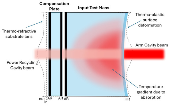
Figure 2.
Picture of the thermal effects on an input test mass. Both the thermo-elastic and thermo-optic effects are represented.
Now, the thermal effects in the ITMs and ETMs are the only ones that have to be tackled to ensure the proper working of the detector. This is because these optics are placed in the arm cavities of the interferometer [2], where the highest amount of power is circulating, so the effect of the optical aberrations is the strongest. The thermal effects in other core optics—Power Recycling Mirror, Signal Recycling Mirror, and Beamsplitter—are currently negligible and do not need any compensation, although the thermal actuators have been installed on these optics as well anyway, should any compensation be needed.
The persistent dependence of WD on the circulating power poses a major challenge in future GW detectors. The planned upgrades render their mitigation not only essential but also a subject of ongoing research and development in optics for which the thermal compensations is currently not necessary—like the Beamsplitter [20], building upon the advanced technologies already in use and described in the next section.
4. Design and Operation of a Thermal Compensation System
To mitigate WDs, interferometric GW detectors rely on an advanced Thermal Compensation System (TCS). The principle of operation of the TCS is illustrated in Figure 3, where a schematic example is shown. The TCS operates by monitoring WDs and applying a complementary distortion—equal in magnitude but opposite in direction—to restore the design configuration. A critical step in designing the TCS involves defining the requirements for aberration control, as detailed below.
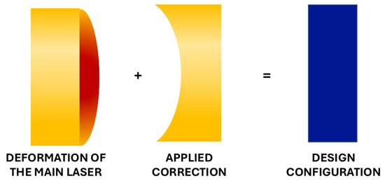
Figure 3.
Schematic representation of the TCS principle of operation. The main laser induces deformation in the optics within the Fabry–Perot cavities due to absorption. The TCS actuators generate an opposing deformation—equal in magnitude but opposite in sign—on the same optic. The resulting combination restores the design configuration, leaving a residual deformation within the correction requirements.
4.1. Requirements
The optical property that the TCS has chosen as a figure of merit to assess the quality of the correction is the control of the power in the fundamental mode TEM of the cavity00 (the Transverse Electromagnetic Mode (TEM) is an electromagnetic field pattern lying in the plane perpendicular to the direction of propagation of the considered radiation, i.e., the laser radiation. The fundamental mode TEM00 is the lowest order in which the laser beam can be decomposed and it has the same shape of a Gaussian beam [21].). Therefore, a natural choice for this purpose is to minimize the fraction of power , which is scattered out of the TEM00 mode due to the presence of optical aberrations
where is a matrix representing the scattering of the electromagnetic field between modes, is the field of the TEM00 mode out of the set of basis modes, is the WD, and the last passage is held in the limit , i.e., that of a small WD. The ideal scenario is , i.e., the TEM00 is not affected at all by any WD. The target of the TCS is to maintain the fraction of power scattered out of the TEM00 within the maximum acceptable level of SNR reduction (usually an acceptable value is a reduction of no more than 10% of the total SNR.), i.e., . To achieve this, the TCS components must meet specific design criteria [18]:
- Actuation range. The actuators must handle the largest expected WD——with additional capacity to accommodate variations over time—at least by a factor of two.
- Actuation precision. Actuators must achieve sufficient resolution to prevent introducing new distortions that exceed allowable SNR losses
- Sensor range and precision. The sensor must be able to detect—while the detector still operates—the maximum expected residual distortion. Regarding its precision, it is usually required to be good enough such that random error in any measurement is less than one order of magnitude of the root mean square (RMS) tolerable WD .
- Bandwidth. The actuator must be able to properly compensate for any thermal change to keep within the maximum acceptable value. The bandwidth is computed from the thermal time constant of the effect to be compensated for. For static WDs, a DC-only control is usually required.
- Noise. Both sensors and actuators can inject noise at all frequencies—including in the sensing bandwidth of the detector, in which it could even limit and dominate the sensitivity in a specific frequency range. Therefore, the injected noise of the actuators and their couplings with the interferometer must be properly computed and considered in the design phase.
4.2. Sensors
To monitor WD, two different types of sensors are currently engaged in the GW detectors. The first ones directly measure the WDs induced by individual optics, while the other ones derive signals from the interferometer’s optical mode.
4.2.1. Direct Sensing: Hartmann Wavefront Sensor
Hartmann Wavefront Sensors (HWS) [22,23] are used to directly measure the thermally induced WD on each mirror. The HWS is composed of a Charge-Coupled Device (CCD), an opaque plate containing an array of apertures known as the Hartmann Plate (HP), two fins used to dissipate the heat of the CCD, and two slabs of copper to carry the heat from the CCD to the fins.
HWS is a differential sensor, i.e., it computes the difference between a wavefront acquired at a generic time t and a reference one at the beginning of the measurement. The probe beam used to detect aberrations is generated by a Superluminescent Light Emitting Diode (SLED) (SLED is a broadband source characterized by a short coherence length that eliminates interference between stray beams.). The probe beam impinges on the mirror under test through a dedicated optical setup [24] and is reflected on the same optical path, reaching the HP. The working principle of the HWS is displayed in Figure 4 and is fully addressed in [23,24].
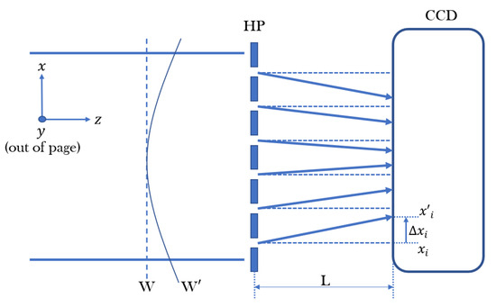
Figure 4.
Working principle of the HWS. W and are the reference wavefront and the related position of the i-th spot resulting from it, respectively, while W’ and refer to a generic wavefront acquired during the measurement.
The direct sensing main advantage is that the measurements carried on with the HWSs are mostly decoupled from all other optics. However, this configuration does not directly sample the distortion of the interferometer mode itself.
4.2.2. Indirect Sensing: Phase Camera
The Phase Camera (PC) [25] sensor measures the amplitude and phase of the electromagnetic fields in the interferometer and produces relative maps. These maps are obtained using two beams: the signal beam, containing the information on the thermal status of the mirrors, and a reference beam, picked up before the laser enters the interferometer, not containing information about any cavity aberrations. These two signals, after recombination on a beamsplitter, reach a scanner and then are detected by a photodiode [26]. PC is a complementary sensor to the above-described HWS, with the difference being that it takes global measurements, i.e., contrary to the HWSs, it cannot distinguish contributions from individual optics.
4.3. Actuators
4.3.1. Ring Heaters
As introduced in Section 3.2, the thermo-elastic deformation induces a change in the RoC of the mirrors. To compensate for this effect and restore the nominal configuration, TCS uses an adaptive optical actuator called Ring Heater (RH) [27,28].
The RH is composed of two heaters and a shield. Each heater consists of a coil of nickel chrome wires wrapped around a ring of pyrex. The wires are heated via the Joule effect and the high emissivity of the pyrex assures an effective radiation of power. A complete view of an RH and its mounting around the mirror is displayed in Figure 5. As shown, the RH is mechanically centred around all optics within 0.5 cm, which allows users to easily identify the centre of the related test mass (TM) on the HWS maps [29]. RHs are effective for compensating static distortions due to manufacturing imperfections or steady-state heating.
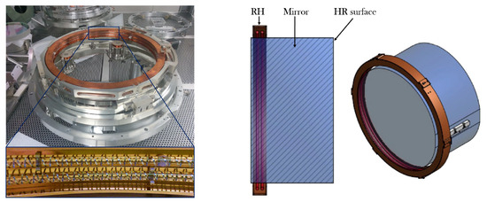
Figure 5.
Left: a RH inside the holder ready to be integrated in a payload (top), with a zoom on its inner part in which the two pyrex rings and the nickel chrome wrapped wires are visible (bottom). Right: CAD drawing showing a section and a three-quarters view of the RH surrounding a mirror.
4.3.2. CO2 Lasers Projector
The correction of thermal lensing caused by the thermo-optic effect is performed by heating the mirror, but through a method distinct from the one previously described. Thermal lensing arises primarily from the radial component of the temperature gradient. To counteract this, the compensation involves heating the periphery of the mirror, effectively cancelling out the temperature gradient within it. A suitable approach for correcting thermal lensing is to shine a radiation on the optic, which is completely absorbed in a thin surface layer. For mirrors made by fused silica, this requires the use of laser radiation with > 5 μm [30], like high-power CO2 lasers emitting at λ = 10.6 μm. This wavelength allows for the generation of a variety of heating profiles, from which the most suitable one can be selected. To minimize noise coupling between the laser and the optics, the CO2 laser is not directed directly onto the mirror but instead onto an additional transmissive optic known as the Compensation Plate (CP) [31]. The CP enables the independent control of both the thermal lensing compensation and the correction of the RoC [30]. A schematic example of this actuation, with the CO2 laser applied to one of the Advanced Virgo ITMs, is shown in Figure 6.
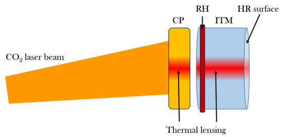
Figure 6.
Actuation of the CO2 laser on the CP placed behind the ITM.
The actuation patterns projected on the CP are the Central Heating (CH) and the Double Axicon System (DAS) [24,27]. The former consists of a Gaussian beam shone at the centre of the CP with the same dimensions as the main GAY laser beam. This pattern generates a negative lens, with the same sign as the thermal lensing caused by the self-heating of the optics from the main GAY beam. Its purpose is to mitigate thermal transients when the interferometer loses the lock, helping the system to recover the correct working point faster. The latter, on the other hand, is created by superimposing two annular beams of different sizes and radii to form a donut-shaped profile. The annular pattern is produced using an axicon—a lens with a conical surface that can convert a Gaussian laser beam into an annular one. Unlike the CH, the DAS generates a positive lens. It is used mainly to correct the thermal lensing due to uniform coating absorption in the ITMs and the cold defects, showing a high degree of spherical aberration.
These two actuation patterns are static, i.e., they are applied in a “set and go” mode and they are usually not changed during a data-taking period. However, in the case of asymmetric WD—such as surface figure errors or non-uniform absorption—it becomes necessary to implement a dynamic correction. Although these aberrations are not critical for the current generation of GW detectors yet, they are expected to have a significant impact on third-generation instruments. For this reason, various research and development efforts [27,32,33] are underway to identify the most effective strategies for addressing these challenges.
5. Future Prospects for Thermal Effects Mitigation
The TCS has proven to be remarkably versatile, addressing challenges well beyond its original design scope. Experience gained from Advanced Virgo demonstrates its adaptability, as the TCS was used not only for compensating static thermal effects but also to meet unforeseen commissioning needs and to support advanced operational goals. Notable examples include adaptive mode matching for squeezed beam injection and mitigating round-trip losses in filter cavities. These applications highlight the critical role of TCS in current detectors and suggest their potential as indispensable tools for tackling optical aberrations in next-generation GW observatories.
However, significant advancements are still needed. To meet the stringent requirements of ET-HF, future TCS must achieve greater flexibility, independence and redundancy. Sensors should be designed to provide decoupled and precise observations, while actuators must effectively control distinct degrees of freedom. Introducing redundant control mechanisms will further improve the overall system versatility by freeing actuation resources and boosting adaptability. These principles—flexibility, independence, and redundancy—are essential for addressing the complex thermal and optical challenges anticipated in next-generation detectors.
As previously mentioned, the higher optical powers expected in the next generation of GW detectors will induce significant transient thermal effects in mirror substrates, particularly for ET-HF which relies on fused silica TM and operates at room temperature. Studies have shown that increasing arm power will require an enhanced TCS, including more powerful RHs, CO2 lasers, and new actuators like FROSTI [34].
Future detectors may also require actuators capable of addressing non-spherically symmetric WDs to manage higher-order optical aberrations. Managing transient thermal effects will be a critical challenge. While HWSs and other innovative tools can monitor these behaviours, the further development of actuators is necessary for effectively mitigating transient distortions [35,36]. To address these complexities, the next generation of TCSs must reproduce intricate heating patterns without compromising detector sensitivity. Dynamic compensation will be essential for correcting all forms of aberrations. Current research is exploring radiative heating arrays [32,37], capable of acting on the high-reflectivity surfaces of optics, and deformable mirrors (DMs) [33], which can imprint phase modulations onto Gaussian beams, holographically converting intensity distributions into the desired profiles.
The radiative heating arrays have been developed to mitigate the irregular wavefront aberrations caused by highly absorbing micro-scale areas on the mirror surfaces, known as Point Absorbers. Unlike other actuators of the TCS, where the laser beam is directed onto the CP, the radiative heating arrays focus their laser beams directly on the high-reflectivity surfaces of optics. These arrays consist of a set of heating elements, typically laser diodes or resistive heaters, combined with optical components such as parabolic reflectors and lenses, to shape and direct the heating pattern precisely onto the affected areas. Their versatility allows them to adapt to different heating requirements and to compensate for a wide range of wavefront distortions. This configuration enables the generation of highly localized and targeted heating profiles.
Otherwise, DMs provide a versatile solution to model the intensity profile of a CO2 laser beam, enabling complementary wavefront correction of non-axisymmetric aberrations in gravitational wave detectors. The adoption of DMs allows for static and adaptive corrections, effectively eliminating the noise introduced by dynamic systems, a crucial requirement for maintaining detector sensitivity. In future high-power configurations, such as those envisioned for the ET-HF, residual non-axisymmetric aberrations may become incompatible with thermal compensation requirements, emphasizing the importance of advanced DM implementations. Like current actuators of the TCS, the laser beam incident on the DM is then directed onto the CP, allowing for the generation of an optimal heating profile to correct the aberrations. To address this, a Modified Gerchberg–Saxton algorithm, integrated with the measured influence function matrix of the DM, has been developed to accurately determine the phase profile needed to generate optimal heating patterns for aberration correction.
These advancements will be critical for ensuring the performance and reliability of third-generation detectors.
6. Conclusions
In this paper, an overview of the optical aberrations and the importance of their correction has been presented. While potential advancements in core optic materials and performance may reduce mirror absorption, a fraction of the laser power will still be absorbed, leading to thermal effects. The induced WDs—if not adequately corrected—could strongly limit the performance of a GW detector. To properly tackle them, the TCS was designed, implemented, and commissioned. Thanks to its actuators, WDs have been already properly compensated in the current generation of GW interferometric detectors, ensuring their proper operation. However, the significantly higher power circulating in the arms of ET-HF will present new challenges to the TCS. Despite potential improvements in mirrors’ absorption, the expected optical aberrations will be more offending than the ones currently compensated. Additionally, new types of aberrations—currently negligible or not impacting the operation of the GW detectors—are expected to play a significant role in the stability and controllability of the interferometers. Therefore, the actuators will need to be enhanced or redesigned, and new ones will be developed to adapt the TCS to the new demanding requirements and challenges posed by ET-HF.
Author Contributions
Conceptualization, M.C., C.T., L.A. and D.L.; resources, M.C., C.T., L.A. and D.L.; writing—original draft preparation, M.C., C.T., L.A. and D.L.; writing—review and editing, M.C., C.T., L.A. and D.L.; visualization, M.C., C.T., L.A. and D.L. All authors have read and agreed to the published version of the manuscript.
Funding
This research received no external funding.
Institutional Review Board Statement
Not applicable.
Informed Consent Statement
Not applicable.
Data Availability Statement
No new data were created or analysed in this study. Data sharing is not applicable to this article.
Conflicts of Interest
The authors declare no conflicts of interest. The funders had no role in the design of the study; in the collection, analyses, or interpretation of data; in the writing of the manuscript; or in the decision to publish the results.
Abbreviations
The following abbreviations are used in this manuscript:
| CCD | Charge-Coupled Device |
| CH | Central Heating |
| CO | Core Optics |
| CP | Compensation Plate |
| CTN | Coating Thermal Noise |
| DAS | Double Axicon System |
| DM | Deformable Mirror |
| ET | Einstein Telescope |
| ET-HF | Einstein Telescope High-Frequency |
| ET-LF | Einstein Telescope Low-Frequency |
| ETM | End Test Mass |
| GW | Gravitational Wave |
| HOM | Higher Order Mode |
| HP | Hartmann Plate |
| HWS | Hartmann Wavefront Sensor |
| ITM | Input Test Mass |
| KAGRA | Kamioka Gravitational Wave Detector |
| LMA | Laboratoire des Matériaux Avancés |
| PC | Phase Camera |
| RH | Ring Heater |
| RMS | Root Mean Square |
| RoC | Radius of Curvature |
| SLED | Superluminescent Light Emitting Diode |
| SNR | Signal-to-Noise Ratio |
| TCS | Thermal Compensation System |
| TM | Test Mass |
| WD | Wavefront Distortion |
References
- Abbott, B.P. et al. [The LIGO Scientific Collaboration] Advanced LIGO. Class. Quantum Gravity 2015, 32, 074001. [Google Scholar] [CrossRef]
- Acernese, F.; Agathos, M.; Agatsuma, K.; Aisa, D.; Allemandou, N.; Allocca, A.; Amarni, J.; Astone, P.; Balestri, G.; Ballardin, G.; et al. Advanced Virgo: A second-generation interferometric gravitational wave detector. Class. Quantum Gravity 2014, 32, 024001. [Google Scholar] [CrossRef]
- Abbott, B.P. et al. [LIGO Scientific Collaboration and Virgo Collaboration] Observation of Gravitational Waves from a Binary Black Hole Merger. Phys. Rev. Lett. 2016, 116, 061102. [Google Scholar] [CrossRef] [PubMed]
- Abbott, B.P. et al. [LIGO Scientific Collaboration and Virgo Collaboration] GWTC-1: A Gravitational-Wave Transient Catalog of Compact Binary Mergers Observed by LIGO and Virgo during the First and Second Observing Runs. Phys. Rev. X 2019, 9, 031040. [Google Scholar] [CrossRef]
- Abbott, B.P. et al. [LIGO Scientific Collaboration and Virgo Collaboration] GWTC-2: Compact Binary Coalescences Observed by LIGO and Virgo During the First Half of the Third Observing Run. Phys. Rev. X 2021, 11, 021053. [Google Scholar] [CrossRef]
- Abbott, R. et al. [LIGO Scientific Collaboration] GWTC-2.1: Deep Extended Catalog of Compact Binary Coalescences Observed by LIGO and Virgo During the First Half of the Third Observing Run. arXiv 2021. [Google Scholar] [CrossRef]
- Abbott, R. et al. [LIGO Scientific Collaboration, Virgo Collaboration, and KAGRA Collaboration] GWTC-3: Compact Binary Coalescences Observed by LIGO and Virgo During the Second Part of the Third Observing Run. arXiv 2021. [Google Scholar] [CrossRef]
- Nitz, A.H.; Kumar, S.; Wang, Y.F.; Kastha, S.; Wu, S.; Schäfer, M.; Dhurkunde, R.; Capano, C.D. 4-OGC: Catalog of Gravitational Waves from Compact Binary Mergers. Astrophys. J. 2023, 946, 59. [Google Scholar] [CrossRef]
- Zhang, T.; Danilishin, S. Conceptual Design and Noise Budget of Einstein Telescope (ET Sensitivity Curve Update). Et Internal Note et-0007b-23. 2023. Available online: https://apps.et-gw.eu/tds/?r=18177 (accessed on 1 December 2024).
- Abernathy, M.; Acernese, F.; Ajith, P.; Allen, B.; Amaro Seoane, P.; Andersson, N.; Aoudia, S.; Astone, P.; Krishnan, B.; Barack, L.; et al. Einstein Gravitational Wave Telescope Conceptual Design Study. Technical Report, ET. ET-0106C-10. 2011. Available online: http://www.et-gw.eu/etdsdocument (accessed on 1 December 2024).
- The VIRGO Collaboration. The VIRGO large mirrors: A challenge for low loss coatings. Class. Quantum Gravity 2004, 21, S935–S945. [Google Scholar] [CrossRef]
- Penn, S.D.; Sneddon, P.H.; Armandula, H.; Betzwieser, J.C.; Cagnoli, G.; Camp, J.; Crooks, D.R.M.; Fejer, M.M.; Gretarsson, A.M.; Harry, G.M.; et al. Mechanical loss in tantala/silica dielectric mirror coatings. Class. Quantum Gravity 2003, 20, 2917–2928. [Google Scholar] [CrossRef]
- Crooks, D.R.M.; Cagnoli, G.; Fejer, M.M.; Gretarsson, A.; Harry, G.; Hough, J.; Nakagawa, N.; Penn, S.; Route, R.; Rowan, S.; et al. Experimental measurements of coating mechanical loss factors. Class. Quantum Gravity 2004, 21, S1059–S1065. [Google Scholar] [CrossRef][Green Version]
- Flaminio, R.; Franc, J.; Michel, C.; Morgado, N.; Pinard, L.; Sassolas, B. A study of coating mechanical and optical losses in view of reducing mirror thermal noise in gravitational wave detectors. Class. Quantum Gravity 2010, 27, 084030. [Google Scholar] [CrossRef]
- Pinard, L.; Michel, C.; Sassolas, B.; Balzarini, L.; Degallaix, J.; Dolique, V.; Flaminio, R.; Forest, D.; Granata, M.; Lagrange, B.; et al. Mirrors used in the LIGO interferometers for first detection of gravitational waves. Appl. Opt. 2017, 56, C11–C15. [Google Scholar] [CrossRef] [PubMed]
- Cole, G.D.; Groblacher, S.; Gugler, K.; Gigan, S.; Aspelmeyer, M. Monocrystalline AlxGa1-xAs heterostructures for high-reflectivity high-Q micromechanical resonators in the megahertz regime. Appl. Phys. Lett. 2008, 92, 261108. [Google Scholar] [CrossRef]
- Beausoleil, R.G.; Gustafson, E.K.; Fejer, M.M.; D’Ambrosio, E.; Kells, W.; Camp, J. Model of thermal wave-front distortion in interferometric gravitational-wave detectors. I. Thermal focusing. J. Opt. Soc. Am. B 2003, 20, 1247–1268. [Google Scholar] [CrossRef]
- Saulson, P. Advanced Interferometric Gravitational-Wave Detectors; WSP: Singapore, 2019. [Google Scholar] [CrossRef]
- Ryan Christopher, L. Active Wavefront Correction in Laser Interferometric Gravitational Wave Detectors. Ph.D. Thesis, MIT, Cambridge, MA, USA, 2003. [Google Scholar]
- Nadji, S.; Wittel, H.; Mukund, N.; Lough, J.; Affeldt, C.; Bergamin, F.; Brinkmann, M.; Kringel, V.; Lück, H.; Weinert, M.; et al. GEO 600 beam splitter thermal compensation system: New design and commissioning. Class. Quantum Gravity 2024, 42, 025009. [Google Scholar] [CrossRef]
- Siegman, A.E. Lasers; University Science Books: Sausalito, CA, USA, 1986. [Google Scholar]
- Brooks, A. Hartmann Wavefront Sensors for Advanced Gravitational Wave Interferometers. Ph.D. Thesis, University of Adelaide, Adelaide, Australia, 2007. [Google Scholar]
- Aiello, L.; Palma, P.P.; Lorenzini, M.; Cesarini, E.; Cifaldi, M.; Fronzo, C.D.; Lumaca, D.; Minenkov, Y.; Nardecchia, I.; Rocchi, A.; et al. Thermal defocus-free Hartmann Wavefront Sensors for monitoring aberrations in Advanced Virgo. Class. Quantum Gravity 2024, 41, 125001. [Google Scholar] [CrossRef]
- Nardecchia, I. Detecting Gravitational Waves with Advanced Virgo. Galaxies 2022, 10, 28. [Google Scholar] [CrossRef]
- van der Schaaf, L.; Agatsuma, K.; van Beuzekom, M.; Gebyehu, M.; van den Brand, J. Advanced Virgo phase cameras. J. Phys. Conf. Ser. 2016, 718, 072008. [Google Scholar] [CrossRef]
- van der Schaaf, L. The Phase Cameras of Advanced Virgo. Ph.D. Thesis, Vrije Universiteit Amsterdam, Amsterdam, The Netherlands, 2020. [Google Scholar]
- Aiello, L.; Cesarini, E.; Fafone, V.; Lorenzini, M.; Minenkov, Y.; Nardecchia, I.; Rocchi, A.; Sequino, V. Thermal compensation system in advanced and third generation gravitational wave interferometric detectors. J. Phys. Conf. Ser. 2019, 1226, 012019. [Google Scholar] [CrossRef]
- Nardecchia, I.; Minenkov, Y.; Lorenzini, M.; Aiello, L.; Cesarini, E.; Lumaca, D.; Malvezzi, V.; Paoletti, F.; Rocchi, A.; Fafone, V. Optimized radius of curvature tuning for the virgo core optics. Class. Quantum Gravity 2023, 40, 055004. [Google Scholar] [CrossRef]
- Aiello, L. Development of New Approaches for Optical Aberration Control in Gravitational Wave Interferometersl. Ph.D. Thesis, SISSA and GSSI, Physics Division, L’Aquila, Italy, 2019. Available online: https://iris.gssi.it/handle/20.500.12571/9702 (accessed on 1 December 2024).
- The Virgo Collaboration. Advanced Virgo Technical Design Report. Virgo Internal Note vir-0128a-12. 2012. Available online: https://tds.virgo-gw.eu/?content=3&r=9317 (accessed on 1 December 2024).
- Rocchi, A. Thermal Effects and Other Wavefront Aberrations in Recycling Cavities. In Advanced Interferometers and the Search for Gravitational Waves: Lectures from the First VESF School on Advanced Detectors for Gravitational Waves; Springer: Cham, Switzerland, 2014; pp. 251–274. [Google Scholar] [CrossRef]
- Cifaldi, M. Mitigation of Anomalous Absorption in the Virgo Core Optics. Ph.D. Thesis, Tor Vergata University of Rome, Department of Physics, Roma, Italy, 2023. [Google Scholar]
- Taranto, C. Upgraded Optical Aberration Correction Techniques for Advanced Virgo Plus: Commissioning toward O4 and Mitigation of Non-Axisymmetric Optical Defects. Ph.D. Thesis, Sapienza University of Rome, Tor Vergata University of Rome and National Institute of Astrophysics, Department of Physics, Roma, Italy, 2023. [Google Scholar]
- Cao, H.T.; Brooks, A.; Kuns, K.E.A. Post-05 thermal modeling A# TCS requirements status of HOM ring heater. In Proceedings of the LIGO-Virgo-KAGRA Biannual Conference, Toyama, Japan, 11–15 September 2023. Conference Presentation LIGO-G2300624. [Google Scholar]
- Hamedan, V.J.; Blair, C.; Liu, J.; Bossilkov, V.; Zhao, C.; Ju, L.; Blair, D.G. Preventing transient parametric instabilities in high power gravitational wave detectors using thermal transient compensation. Class. Quantum Gravity 2017, 34, 145014. [Google Scholar] [CrossRef]
- Hamedan, V.J.; Zhao, C.; Ju, L.; Blair, C.; Blair, D.G. Suppression of thermal transients in advanced LIGO interferometers using CO2 laser preheating. Class. Quantum Gravity 2018, 35, 115006. [Google Scholar] [CrossRef]
- Cifaldi, M.; Cesarini, E.; Fafone, V.; Lorenzini, M.; Lumaca, D.; Minenkov, Y.; Nardecchia, I.; Rocchi, A.; Taranto, C. Coping with anomalous power absorptions in the Advanced Virgo core optics. Nuovo Cim. C 2022, 45, 140. [Google Scholar] [CrossRef]


Disclaimer/Publisher’s Note: The statements, opinions and data contained in all publications are solely those of the individual author(s) and contributor(s) and not of MDPI and/or the editor(s). MDPI and/or the editor(s) disclaim responsibility for any injury to people or property resulting from any ideas, methods, instructions or products referred to in the content. |
© 2025 by the authors. Licensee MDPI, Basel, Switzerland. This article is an open access article distributed under the terms and conditions of the Creative Commons Attribution (CC BY) license (https://creativecommons.org/licenses/by/4.0/).