
Mandibular Third Molar Surgery: Intraosseous Localization of the Inferior Alveolar Nerve Using 3D Double-Echo Steady-State MRI (3D-DESS)


Abstract
:1. Introduction
2. Materials and Methods
2.1. Study Design
2.2. MRI Data Acquisition
2.3. CBCT Data Acquisition
2.4. Image Evaluation
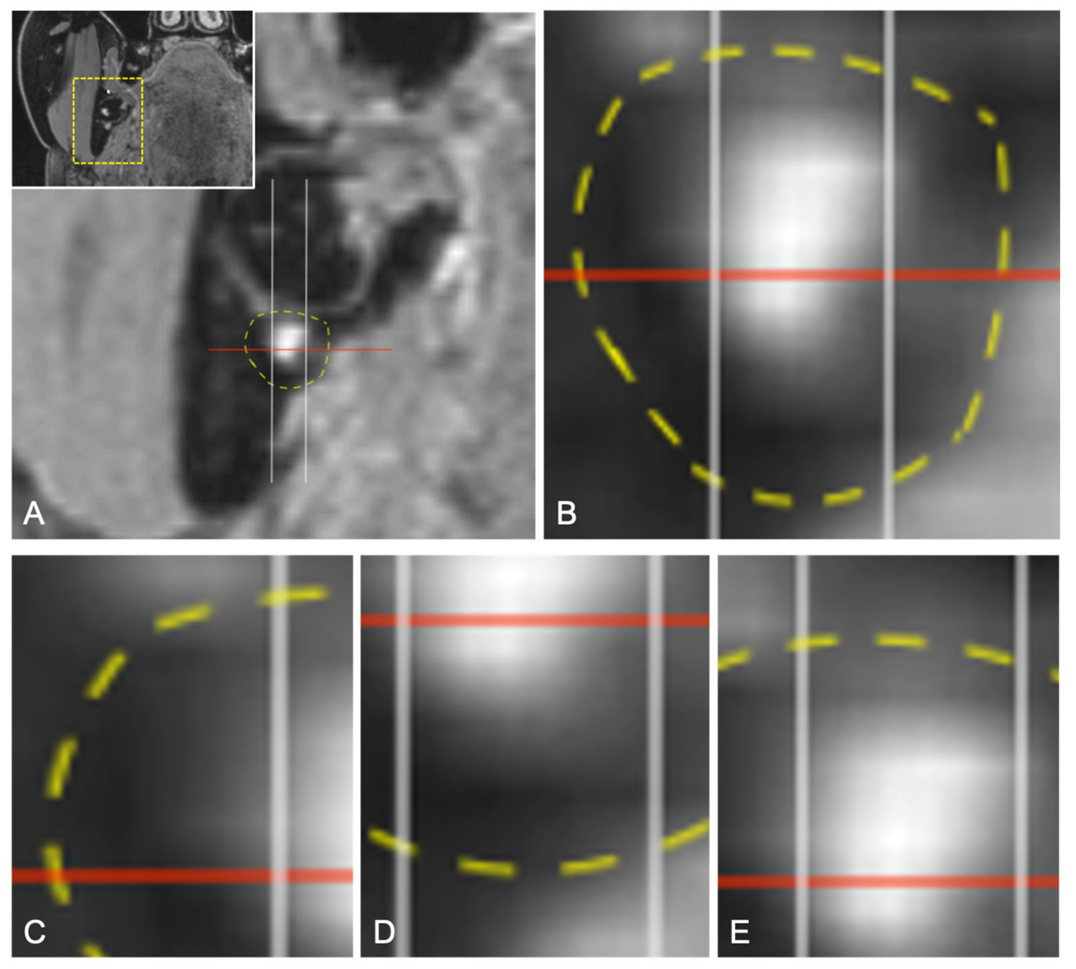
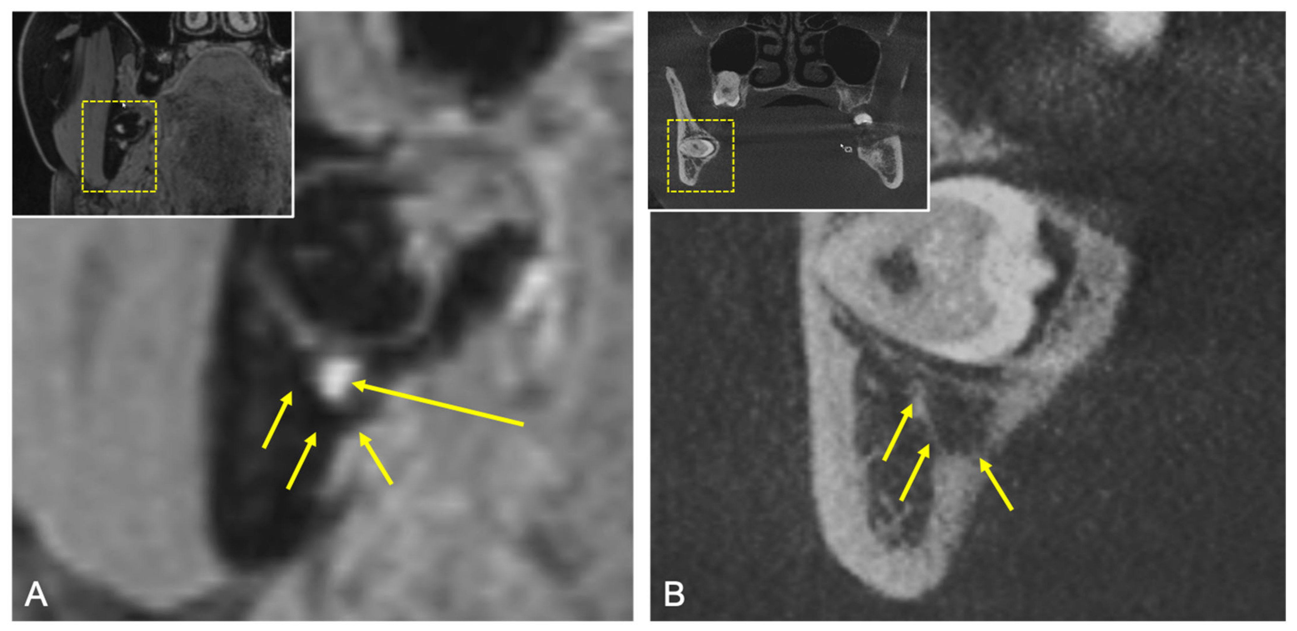
2.4.1. Qualitative Readout
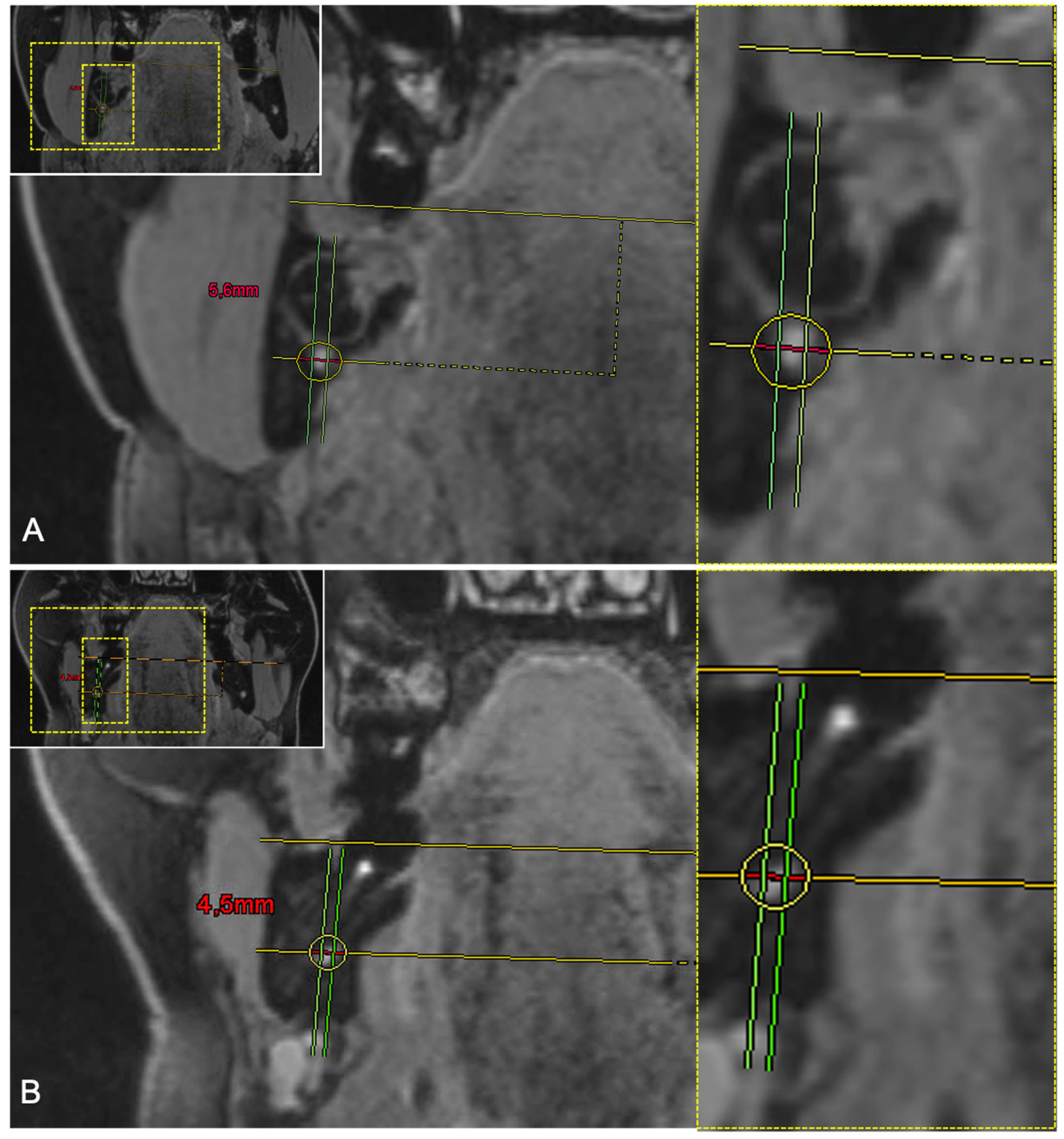
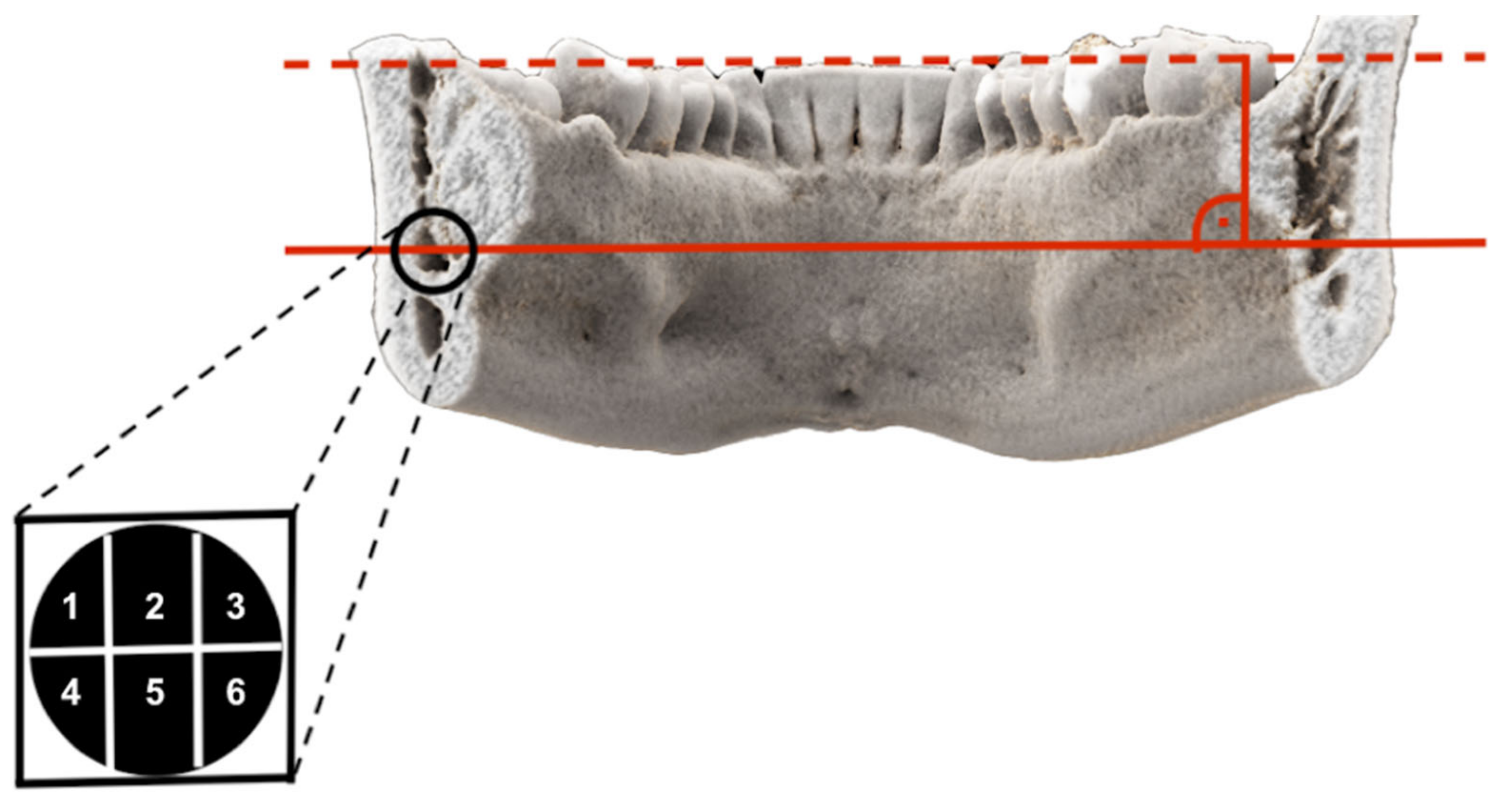
2.4.2. Quantitative Readout
2.5. Statistical Analysis
3. Results
3.1. Qualitative Results
3.2. Quantitative Results
4. Discussion
5. Conclusions
Author Contributions
Funding
Institutional Review Board Statement
Informed Consent Statement
Data Availability Statement
Conflicts of Interest
References
- McLeod, N.M.; Bowe, D.C. Nerve injury associated with orthognathic surgery. Part 2: Inferior alveolar nerve. Br. J. Oral Maxillofac. Surg. 2016, 54, 366–371. [Google Scholar] [CrossRef] [PubMed]
- Al-Sabbagh, M.; Okeson, J.P.; Khalaf, M.W.; Bhavsar, I. Persistent pain and neurosensory disturbance after dental implant surgery: Pathophysiology, etiology, and diagnosis. Dent. Clin. North. Am. 2015, 59, 131–142. [Google Scholar] [CrossRef] [PubMed]
- Hillerup, S.; Jensen, R. Nerve injury caused by mandibular block analgesia. Int. J. Oral Maxillofac. Surg. 2006, 35, 437–443. [Google Scholar] [PubMed]
- Gülicher, D.; Gerlach, K.L. Sensory impairment of the lingual and inferior alveolar nerves following removal of impacted mandibular third molars. Int. J. Oral Maxillofac. Surg. 2001, 30, 306–312. [Google Scholar] [CrossRef]
- Jerjes, W.; Swinson, B.; Moles, D.R.; El-Maaytah, M.; Banu, B.; Upile, T.; Kumar, M.; Al Khawalde, M.; Vourvachis, M.; Hadi, H.; et al. Permanent sensory nerve impairment following third molar surgery: A prospective study. Oral Surg. Oral Med. Oral Pathol. Oral Radiol. Endod. 2006, 102, e1–e7. [Google Scholar] [CrossRef]
- Gomes, A.C.; Vasconcelos, B.C.; Silva, E.D.; Caldas, A.e.F.; Pita Neto, I.C. Sensitivity and specificity of pantomography to predict inferior alveolar nerve damage during extraction of impacted lower third molars. J. Oral Maxillofac. Surg. 2008, 66, 256–259. [Google Scholar] [CrossRef] [PubMed]
- Renton, T.; Yilmaz, Z. Managing iatrogenic trigeminal nerve injury: A case series and review of the literature. Int. J. Oral Maxillofac. Surg. 2012, 41, 629–637. [Google Scholar] [CrossRef] [PubMed]
- Robinson, P.P. Observations on the recovery of sensation following inferior alveolar nerve injuries. Br. J. Oral Maxillofac. Surg. 1988, 26, 177–189. [Google Scholar] [CrossRef]
- Lam, N.P.; Donoff, R.B.; Kaban, L.B.; Dodson, T.B. Patient satisfaction after trigeminal nerve repair. Oral Surg. Oral Med. Oral Pathol. Oral Radiol. Endod. 2003, 95, 538–543. [Google Scholar] [CrossRef]
- Matzen, L.H.; Berkhout, E. Cone beam CT imaging of the mandibular third molar: A position paper prepared by the European Academy of DentoMaxilloFacial Radiology (EADMFR). Dentomaxillofac. Radiol. 2019, 48, 20190039. [Google Scholar] [CrossRef]
- Dula, K.; Bornstein, M.M.; Buser, D.; Dagassan-Berndt, D.; Ettlin, D.A.; Filippi, A.; Gabioud, F.; Katsaros, C.; Krastl, G.; Lambrecht, J.T.; et al. SADMFR guidelines for the use of Cone-Beam Computed Tomography/Digital Volume Tomography. Swiss Dent. J. 2014, 124, 1169–1183. [Google Scholar]
- Stratis, A.; Zhang, G.; Jacobs, R.; Bogaerts, R.; Bosmans, H. The growing concern of radiation dose in paediatric dental and maxillofacial CBCT: An easy guide for daily practice. Eur. Radiol. 2019, 29, 7009–7018. [Google Scholar] [CrossRef]
- Ludlow, J.B.; Davies-Ludlow, L.E.; Brooks, S.L.; Howerton, W.B. Dosimetry of 3 CBCT devices for oral and maxillofacial radiology: CB Mercuray, NewTom 3G and i-CAT. Dentomaxillofac. Radiol. 2006, 35, 219–226. [Google Scholar] [CrossRef]
- Nakamura, T. Dental MRI: A road beyond CBCT. Eur. Radiol. 2020, 30, 6389–6391. [Google Scholar] [CrossRef]
- Gahleitner, A.; Solar, P.; Nasel, C.; Homolka, P.; Youssefzadeh, S.; Ertl, L.; Schick, S. Magnetic resonance tomography in dental radiology (dental MRI). Radiologe 1999, 39, 1044–1050. [Google Scholar] [CrossRef] [PubMed]
- Ludwig, U.; Eisenbeiss, A.K.; Scheifele, C.; Nelson, K.; Bock, M.; Hennig, J.; Von Elverfeldt, D.; Herdt, O.; Flügge, T.; Hövener, J.B. Dental MRI using wireless intraoral coils. Sci. Rep. 2016, 6, 23301. [Google Scholar] [CrossRef] [PubMed] [Green Version]
- Prager, M.; Heiland, S.; Gareis, D.; Hilgenfeld, T.; Bendszus, M.; Gaudino, C. Dental MRI using a dedicated RF-coil at 3 Tesla. J. Craniomaxillofac. Surg. 2015, 43, 2175–2182. [Google Scholar] [CrossRef]
- Gray, C.F.; Redpath, T.W.; Smith, F.W.; Staff, R.T. Advanced imaging: Magnetic resonance imaging in implant dentistry. Clin. Oral Implants Res. 2003, 14, 18–27. [Google Scholar] [CrossRef]
- Burian, E.; Probst, F.A.; Weidlich, D.; Cornelius, C.P.; Maier, L.; Robl, T.; Zimmer, C.; Karampinos, D.C.; Ritschl, L.M.; Probst, M. MRI of the inferior alveolar nerve and lingual nerve-anatomical variation and morphometric benchmark values of nerve diameters in healthy subjects. Clin. Oral Investig. 2020, 24, 2625–2634. [Google Scholar] [CrossRef]
- Kirnbauer, B.; Jakse, N.; Rugani, P.; Schwaiger, M.; Magyar, M. Assessment of impacted and partially impacted lower third molars with panoramic radiography compared to MRI-a proof of principle study. Dentomaxillofac. Radiol. 2018, 47, 20170371. [Google Scholar] [CrossRef] [PubMed]
- Ferretti, F.; Malventi, M.; Malasoma, R. Dental magnetic resonance imaging: Study of impacted mandibular third molars. Dentomaxillofac. Radiol. 2009, 38, 387–392. [Google Scholar] [CrossRef] [PubMed]
- Fujii, H.; Fujita, A.; Yang, A.; Kanazawa, H.; Buch, K.; Sakai, O.; Sugimoto, H. Visualization of the Peripheral Branches of the Mandibular Division of the Trigeminal Nerve on 3D Double-Echo Steady-State with Water Excitation Sequence. AJNR Am. J. Neuroradiol. 2015, 36, 1333–1337. [Google Scholar] [CrossRef] [Green Version]
- Probst, M.; Richter, V.; Weitz, J.; Kirschke, J.S.; Ganter, C.; Troeltzsch, M.; Nittka, M.; Cornelius, C.P.; Zimmer, C.; Probst, F.A. Magnetic resonance imaging of the inferior alveolar nerve with special regard to metal artifact reduction. J. Craniomaxillofac. Surg. 2017, 45, 558–569. [Google Scholar] [CrossRef] [PubMed]
- Burian, E.; Sollmann, N.; Ritschl, L.M.; Palla, B.; Maier, L.; Zimmer, C.; Probst, F.; Fichter, A.; Miloro, M.; Probst, M. High resolution MRI for quantitative assessment of inferior alveolar nerve impairment in course of mandible fractures: An imaging feasibility study. Sci. Rep. 2020, 10, 11566. [Google Scholar] [CrossRef]
- Levine, M.H.; Goddard, A.L.; Dodson, T.B. Inferior alveolar nerve canal position: A clinical and radiographic study. J. Oral Maxillofac. Surg. 2007, 65, 470–474. [Google Scholar] [CrossRef]
- Kieser, J.; Kieser, D.; Hauman, T. The course and distribution of the inferior alveolar nerve in the edentulous mandible. J. Craniofac. Surg. 2005, 16, 6–9. [Google Scholar] [CrossRef] [PubMed]
- Kieser, J.A.; Paulin, M.; Law, B. Intrabony course of the inferior alveolar nerve in the edentulous mandible. Clin. Anat. 2004, 17, 107–111. [Google Scholar] [CrossRef]
- Schneider, T.; Filo, K.; Kruse, A.L.; Locher, M.; Grätz, K.W.; Lübbers, H.T. Variations in the anatomical positioning of impacted mandibular wisdom teeth and their practical implications. Swiss Dent. J. 2014, 124, 520–538. [Google Scholar] [PubMed]
- Beck, F.; Austermann, S.; Bertl, K.; Ulm, C.; Lettner, S.; Toelly, A.; Gahleitner, A. Is MRI a viable alternative to CT/CBCT to identify the course of the inferior alveolar nerve in relation to the roots of the third molars? Clin. Oral Investig. 2020, 25, 3861–3871. [Google Scholar] [CrossRef]
- Qin, Y.; Zhang, J.; Li, P.; Wang, Y. 3D double-echo steady-state with water excitation MR imaging of the intraparotid facial nerve at 1.5T: A pilot study. AJNR Am. J. Neuroradiol. 2011, 32, 1167–1172. [Google Scholar] [CrossRef] [Green Version]
- Anderson, L.C.; Kosinski, T.F.; Mentag, P.J. A review of the intraosseous course of the nerves of the mandible. J. Oral Implantol. 1991, 17, 394–403. [Google Scholar] [PubMed]
- Imamura, H.; Sato, H.; Matsuura, T.; Ishikawa, M.; Zeze, R. A comparative study of computed tomography and magnetic resonance imaging for the detection of mandibular canals and cross-sectional areas in diagnosis prior to dental implant treatment. Clin. Implant. Dent. Relat Res. 2004, 6, 75–81. [Google Scholar] [CrossRef] [PubMed]
- Chau, A. Comparison between the use of magnetic resonance imaging and conebeam computed tomography for mandibular nerve identification. Clin. Oral Implants Res. 2012, 23, 253–256. [Google Scholar] [CrossRef] [PubMed]
- Bertl, K.; Heimel, P.; Reich, K.M.; Schwarze, U.Y.; Ulm, C. A histomorphometric analysis of the nature of the mandibular canal in the anterior molar region. Clin. Oral Investig. 2014, 18, 41–47. [Google Scholar] [CrossRef]
- Maftei, G.A.; Popa, C.; Cioloca, D.; Taraboanta, I.; Ciurcanu, O.; Filioreanu, A.M.; Foia, L. A rare case of non-syndromic mandibulary concrescence of third and fourth supranumerary impacted molars. Rom. J. Med Dent. Educ. 2019, 8. [Google Scholar]
- Probst, M.; Burian, E.; Robl, T.; Weidlich, D.; Karampinos, D.; Brunner, T.; Zimmer, C.; Probst, F.A.; Folwaczny, M. Magnetic Resonance Imaging as a Diagnostic Tool for Periodontal Disease: A prospective study with correlation to standard clinical findings—Is there added value? J. Clin. Periodontol. 2021. [Google Scholar] [CrossRef]
- Petersen, L.B.; Olsen, K.R.; Matzen, L.H.; Vaeth, M.; Wenzel, A. Economic and health implications of routine CBCT examination before surgical removal of the mandibular third molar in the Danish population. Dentomaxillofac. Radiol. 2015, 44, 20140406. [Google Scholar] [CrossRef] [Green Version]
- Geethanath, S.; Vaughan, J.T. Accessible magnetic resonance imaging: A review. J. Magn. Reson. Imaging. 2019, 49, e65–e77. [Google Scholar] [CrossRef] [PubMed]
- Senel, F.C.; Duran, S.; Icten, O.; Izbudak, I.; Cizmeci, F. Assessment of the sinus lift operation by magnetic resonance imaging. Br. J. Oral Maxillofac. Surg. 2006, 44, 511–514. [Google Scholar] [CrossRef] [PubMed]
- Crespi, R.; Capparè, P.; Gherlone, E. Sinus floor elevation by osteotome: Hand mallet versus electric mallet. A clinical study. Int. J. Oral Maxillofac. Implants 2012, 27, 1144–1150. [Google Scholar] [PubMed]
- Afzelius, P.; Nielsen, M.Y.; Ewertsen, C.; Bloch, K.P. Imaging of the major salivary glands. Clin. Physiol. Funct. Imaging 2016, 36, 1–10. [Google Scholar] [CrossRef] [PubMed]
- Salgarelli, A.C.; Capparè, P.; Bellini, P.; Collini, M. Usefulness of fine-needle aspiration in parotid diagnostics. Oral Maxillofac. Surg. 2009, 13, 185–190. [Google Scholar] [CrossRef] [PubMed]
- Mercado, F.; Mukaddam, K.; Filippi, A.; Bieri, O.P.; Lambrecht, T.J.; Kühl, S. Fully Digitally Guided Implant Surgery Based on Magnetic Resonance Imaging. Int. J. Oral Maxillofac. Implants 2019, 34, 529–534. [Google Scholar] [CrossRef] [PubMed]


| Patient Characteristics | Total |
|---|---|
| N | 19 |
| Gender, male/female, N | 6/13 |
| Mean (SD) age at scan, years | 30.5 (13) |
| Median age at scan, years | 25 |
| Age range, years | 18–63 |
| Totally evaluated Inferior alveolar nerves | 36 |
| Clinical indication | MTM Surgery |
| Retention types [29] | |
| Type 1, N | 0 |
| Type 2, N | 0 |
| Type 3, N | 11 |
| Type 4, N | 19 |
| Type 5, N | 2 |
| Type 6, N | 0 |
| Type 7, N | 0 |
| No retention | 4 |
| Absent | 2 |
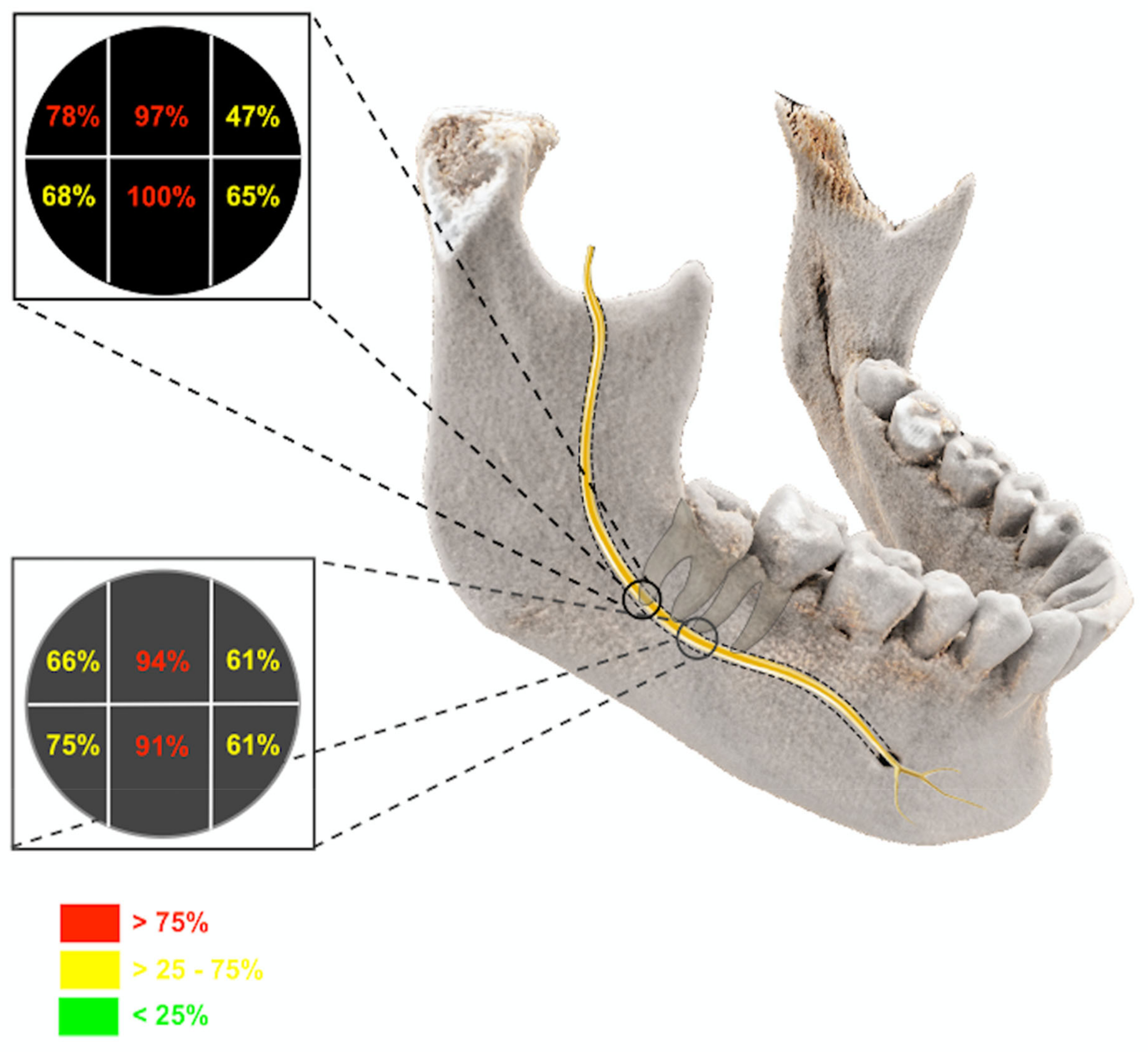
| Third Molar | Segment 1 | Segment 2 | Segment 3 | Segment 4 | Segment 5 | Segment 6 |
|---|---|---|---|---|---|---|
| Generally Yes | 78.9% | 97.4% | 47.4% | 68.4% | 100% | 65.8% |
| If Segment 1 Yes | - | 93.3% | 53.3% | 70% | 96% | 63.3% |
| If Segment 2 Yes | 78.4% | - | 48.7% | 67.6% | 100% | 67.6% |
| If Segment 3 Yes | 88.9% | 100% | - | 61.1% | 100% | 100% |
| If Segment 4 Yes | 88.5% | 96.2% | 46.2% | - | 100% | 69.2% |
| If Segment 5 Yes | 78.9% | 97.4% | 52.6% | 65.8% | - | 65.8% |
| If Segment 6 Yes | 84% | 100% | 72% | 72% | 100% | - |
| Second Molar | Segment 1 | Segment 2 | Segment 3 | Segment 4 | Segment 5 | Segment 6 |
|---|---|---|---|---|---|---|
| Generally Yes | 66.7% | 94.4% | 61% | 75% | 91.6% | 61.1% |
| If Segment 1 Yes | - | 95.8% | 62.5% | 95.8% | 95.8% | 58.3% |
| If Segment 2 Yes | 67.6% | - | 73.5% | 73.5% | 88.2% | 64.7% |
| If Segment 3 Yes | 63.6% | 100% | - | 72.7% | 90.9% | 81.8% |
| If Segment 4 Yes | 85.2% | 96.3% | 59.3% | - | 96.3% | 66.7% |
| If Segment 5 Yes | 66.7% | 90.9% | 63.6% | 75.8% | - | 66.7% |
| If Segment 6 Yes | 68.2% | 100% | 81% | 77.3% | 100% | - |
| Third Molar | Axial | Sagittal | Coronal |
|---|---|---|---|
| IAC in CBCT | 3.9 ± 0.85 mm | 4.04 ± 1.23 mm | 5.3 ± 1.03 mm |
| IAC in MRI | 4.18 ± 0.97 mm | 3.76 ± 1.1 mm | 5.49 ± 0.83 mm |
| IAN in MRI | 2.63 ± 1.19 mm | 2.38 ± 0.89 mm | 4.12 ± 0.98 mm |
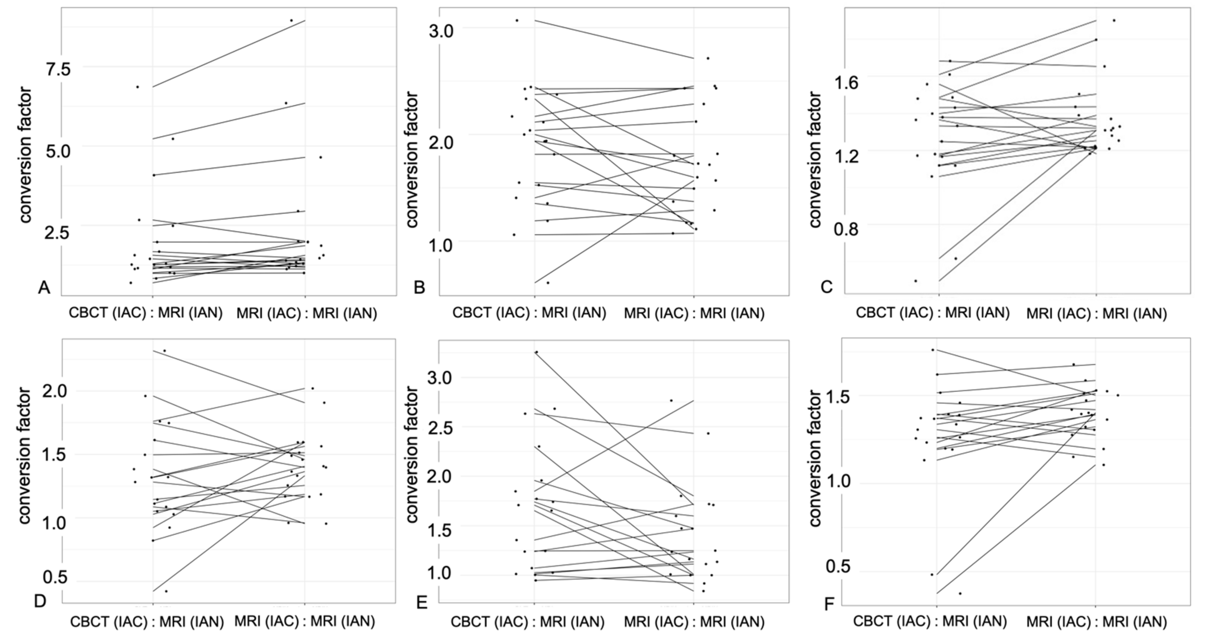
| Conversion factor IAC (CBCT): IAN (MRI) | 2.04 ± 1.953 | 1.86 ± 0.96 | 1.258 ± 0.394 |
| Conversion factor IAC (MRI): IAN (MRI) | 2.367 ± 2.413 | 1.755 ± 0.742 | 1.374 ± 0.252 |
| Second Molar | Axial | Sagittal | Coronal |
|---|---|---|---|
| IAC in CBCT | 4.22 ± 0.78 mm | 3.86 ± 0.9 mm | 5.28 ± 0.83 mm |
| IAC in MRI | 4.23 ± 1.21 mm | 3.09 ± 1.09 mm | 5.62 ± 0.87 mm |
| IAN in MRI | 3.13 ± 0.89 mm | 2.4 ± 0.8 mm | 4.1 ± 0.78 mm |
| Conversion factor IAC (CBCT): IAN (MRI) | 1.692 ± 0.864 | 1.691 ± 0.864 | 1.258 ± 0.407 |
| Conversion factor IAC (MRI): IAN (MRI) | 1.407 ± 0.427 | 1.424± 0.727 | 1.396 ± 0.223 |
Publisher’s Note: MDPI stays neutral with regard to jurisdictional claims in published maps and institutional affiliations. |
© 2021 by the authors. Licensee MDPI, Basel, Switzerland. This article is an open access article distributed under the terms and conditions of the Creative Commons Attribution (CC BY) license (https://creativecommons.org/licenses/by/4.0/).
Share and Cite
Al-Haj Husain, A.; Stadlinger, B.; Winklhofer, S.; Müller, M.; Piccirelli, M.; Valdec, S. Mandibular Third Molar Surgery: Intraosseous Localization of the Inferior Alveolar Nerve Using 3D Double-Echo Steady-State MRI (3D-DESS). Diagnostics 2021, 11, 1245. https://doi.org/10.3390/diagnostics11071245
Al-Haj Husain A, Stadlinger B, Winklhofer S, Müller M, Piccirelli M, Valdec S. Mandibular Third Molar Surgery: Intraosseous Localization of the Inferior Alveolar Nerve Using 3D Double-Echo Steady-State MRI (3D-DESS). Diagnostics. 2021; 11(7):1245. https://doi.org/10.3390/diagnostics11071245
Chicago/Turabian StyleAl-Haj Husain, Adib, Bernd Stadlinger, Sebastian Winklhofer, Marcel Müller, Marco Piccirelli, and Silvio Valdec. 2021. "Mandibular Third Molar Surgery: Intraosseous Localization of the Inferior Alveolar Nerve Using 3D Double-Echo Steady-State MRI (3D-DESS)" Diagnostics 11, no. 7: 1245. https://doi.org/10.3390/diagnostics11071245
APA StyleAl-Haj Husain, A., Stadlinger, B., Winklhofer, S., Müller, M., Piccirelli, M., & Valdec, S. (2021). Mandibular Third Molar Surgery: Intraosseous Localization of the Inferior Alveolar Nerve Using 3D Double-Echo Steady-State MRI (3D-DESS). Diagnostics, 11(7), 1245. https://doi.org/10.3390/diagnostics11071245