An Another Protocol to Make Sulfur Embedded Ultrathin Sections of Extraterrestrial Small Samples


 , , and
Abstract
1. Introduction
2. Materials and Methods
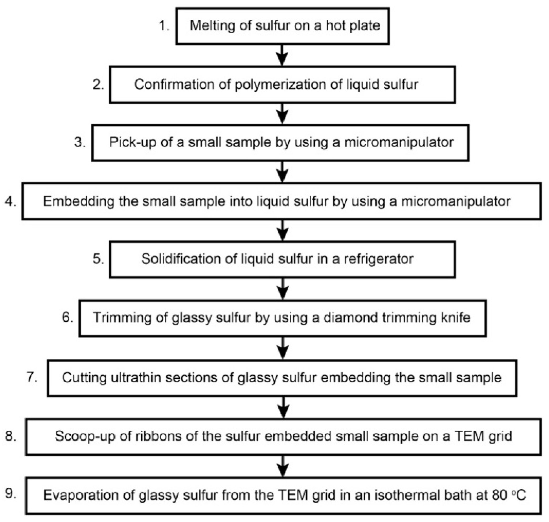
3. Protocol
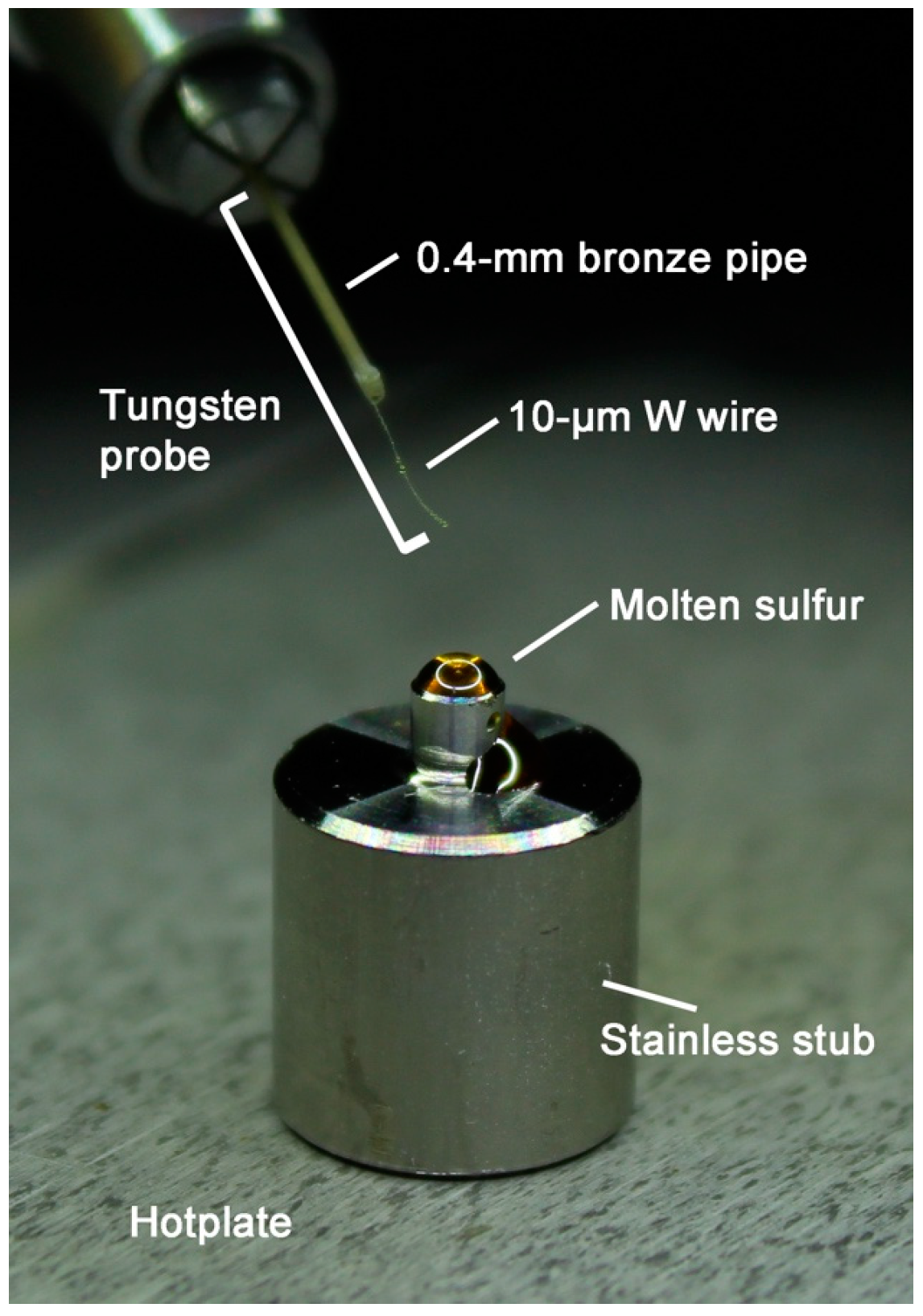
3.1. Stainless Stub
3.2. Use of Viscous Liquid Sulfur
3.3. Details of the Protocol 1: Melting of Sulfur on a Hot Plate
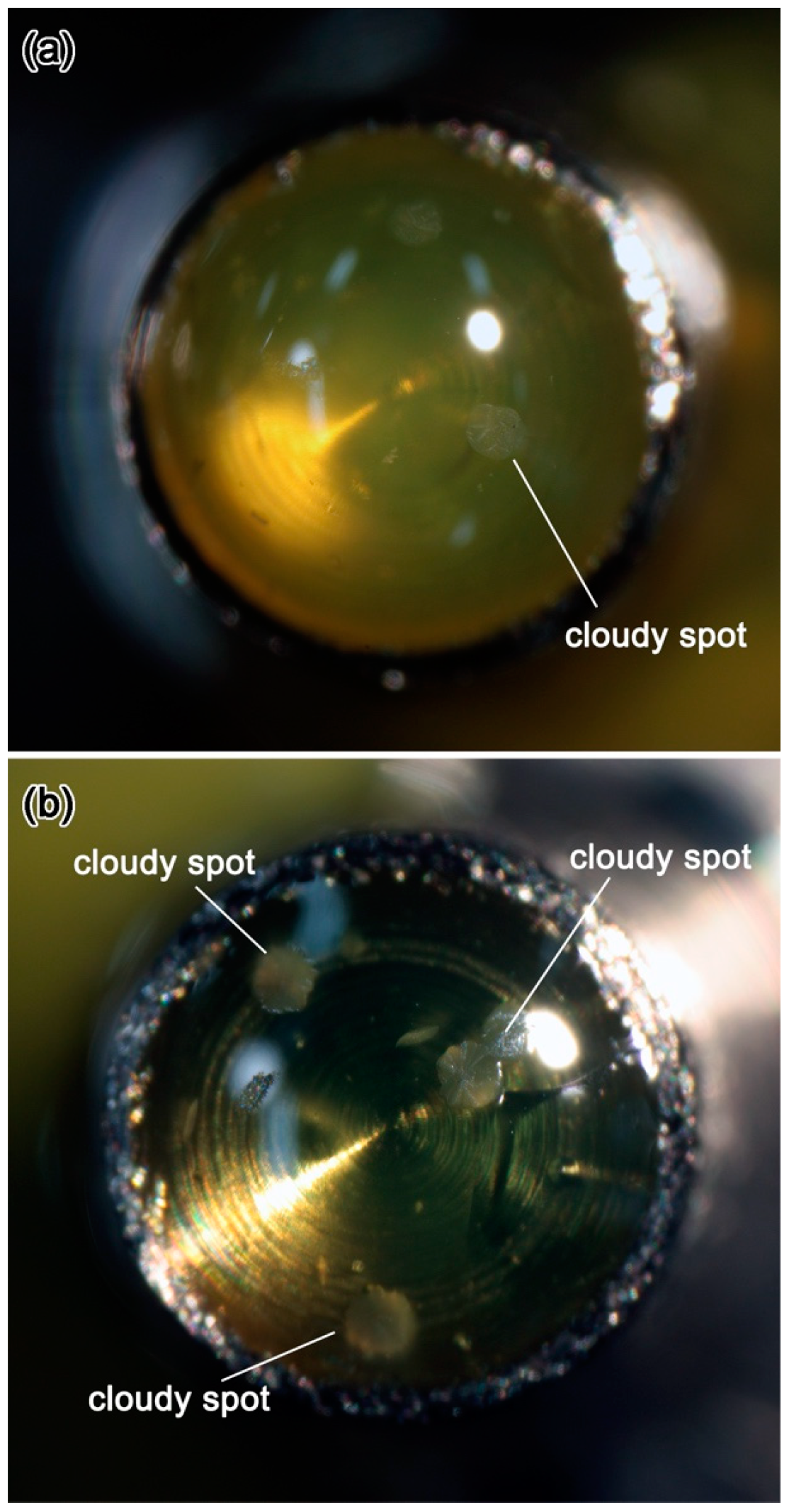
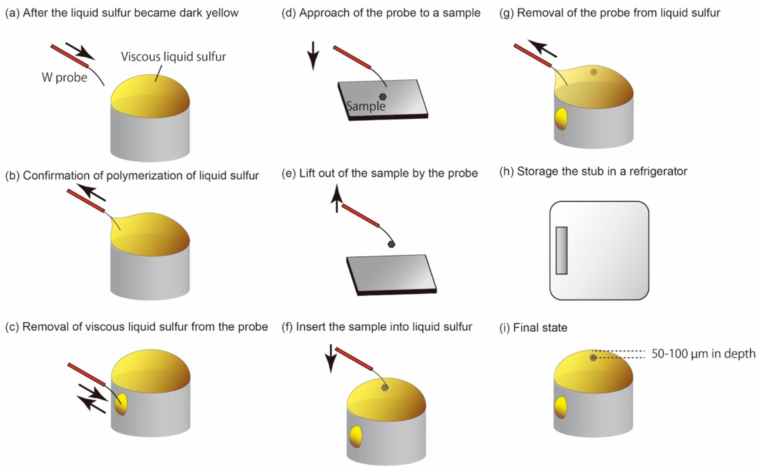
3.4. Details of the Protocol 2: Recognition of Polymerization of Liquid Sulfur
3.5. Details of the Protocols 3–5: Picking-Up and Embedding of Fine-Grained Samples and Solidification of Liquid Sulfur
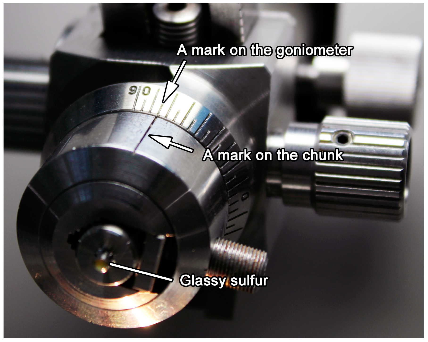
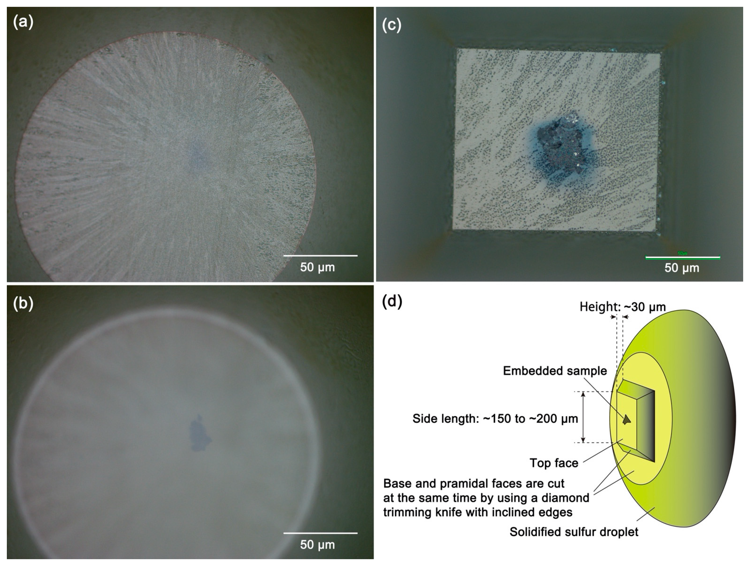
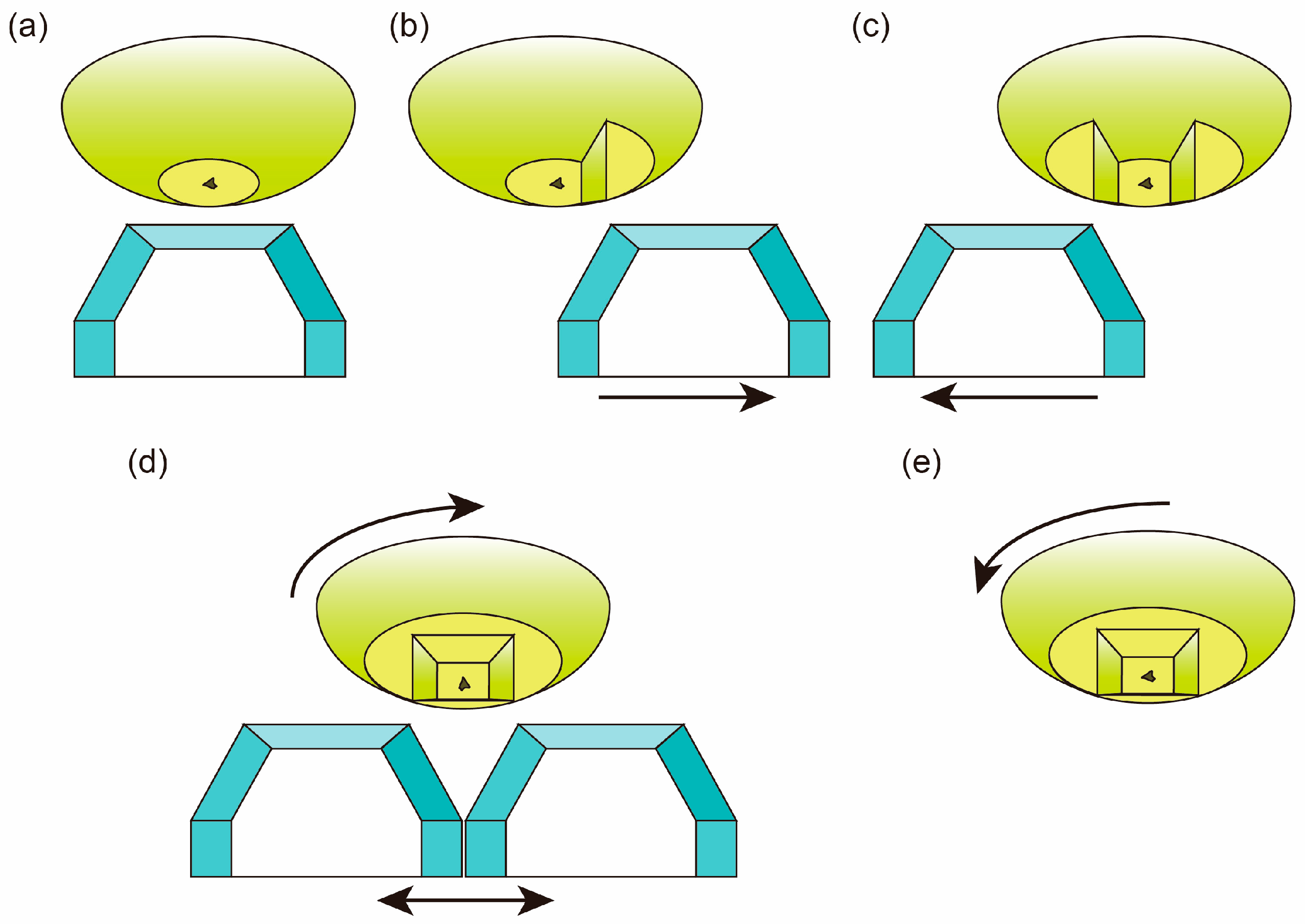
3.6. Details of the Protocol 6: Trimming of Glassy Sulfur by Using a Diamond Knife
3.7. Details of the Protocol 7: Cutting of Ultrathin Sections of Glassy Sulfur Embedding a Small Sample
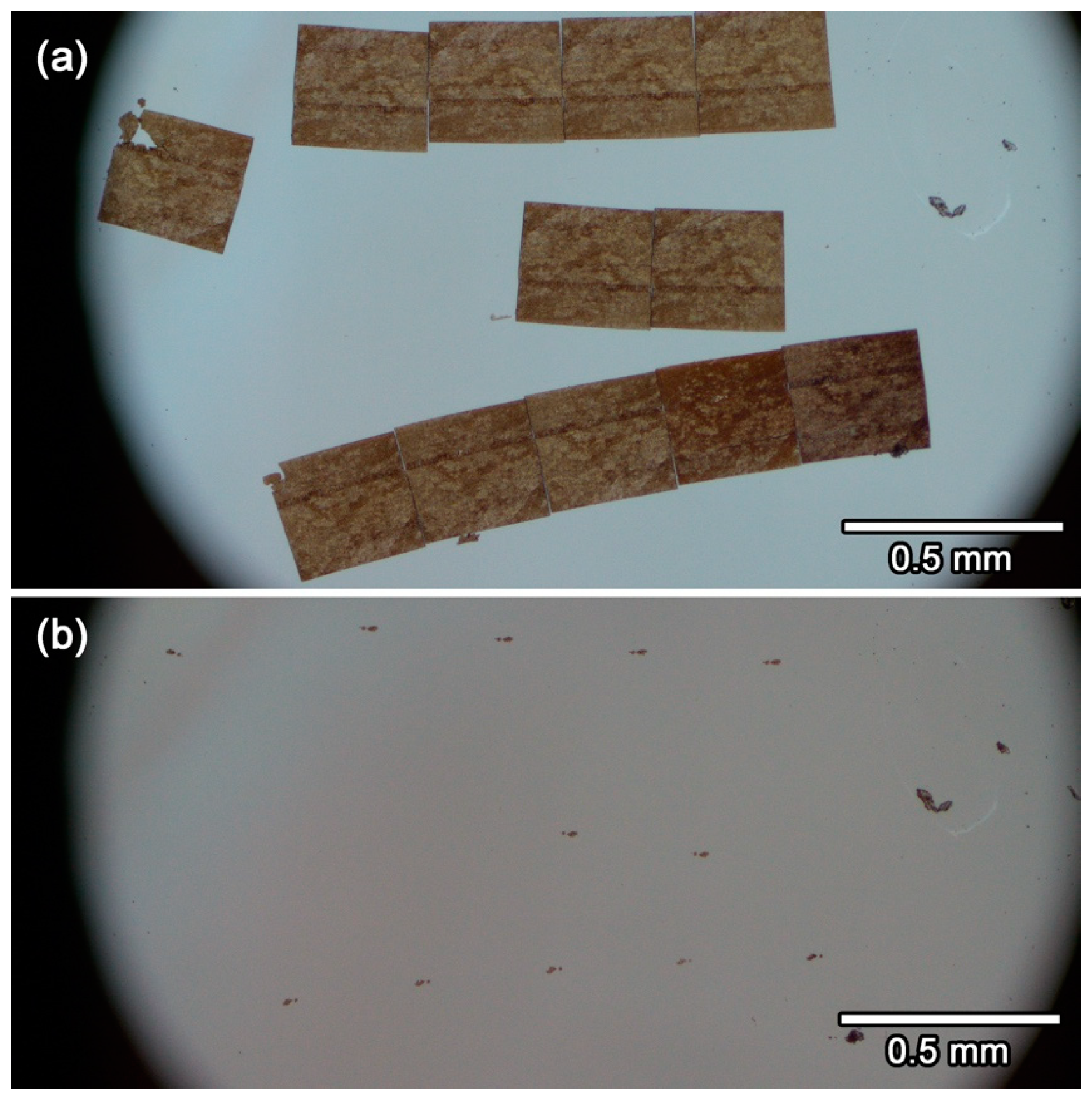
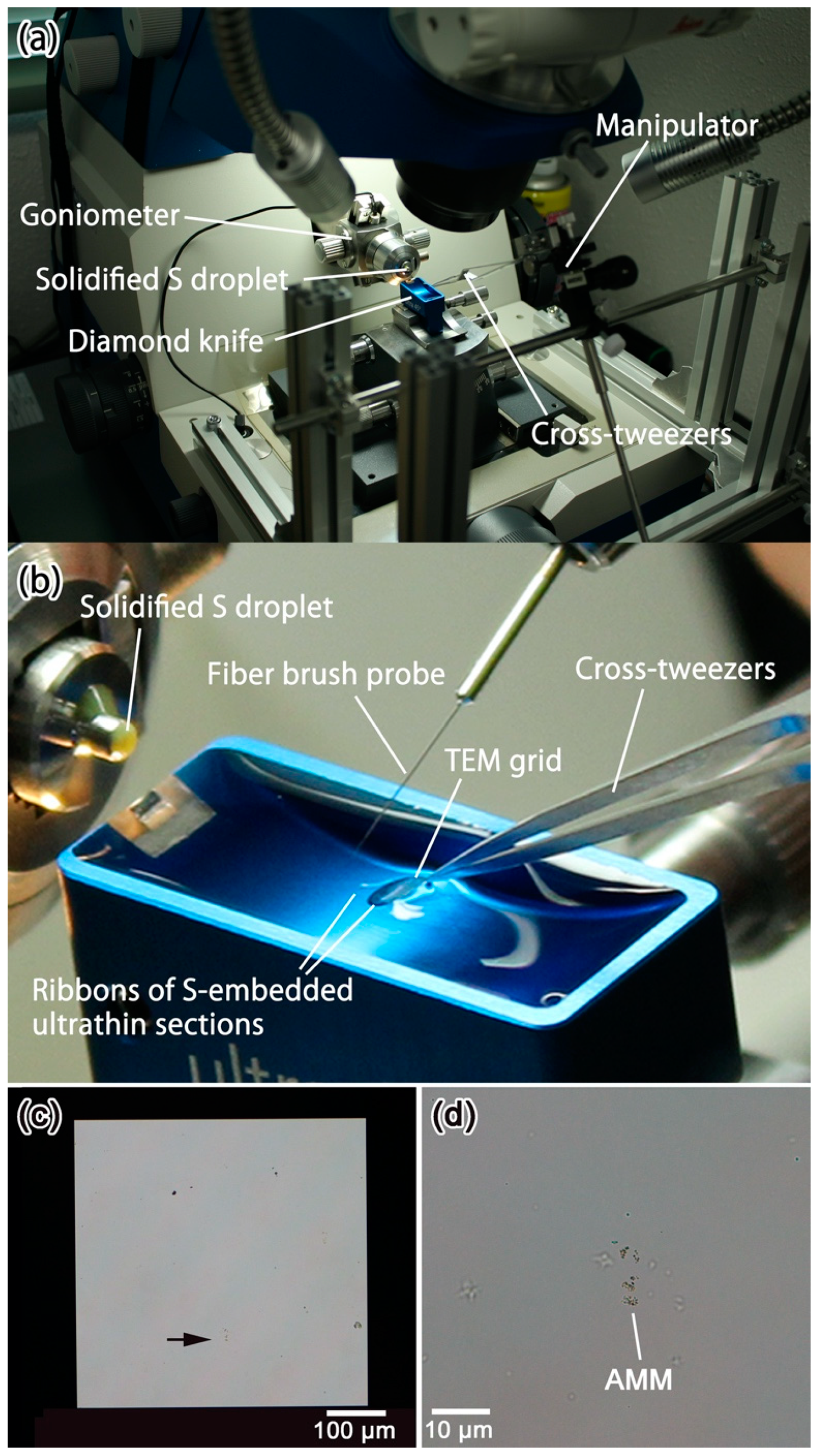
3.8. Details of the Protocol 8–9: Scooping-Up of Ultrathin Section Ribbons of Glassy Sulfur Embedding a Small Sample, Followed by Evaporation of Glassy Sulfur
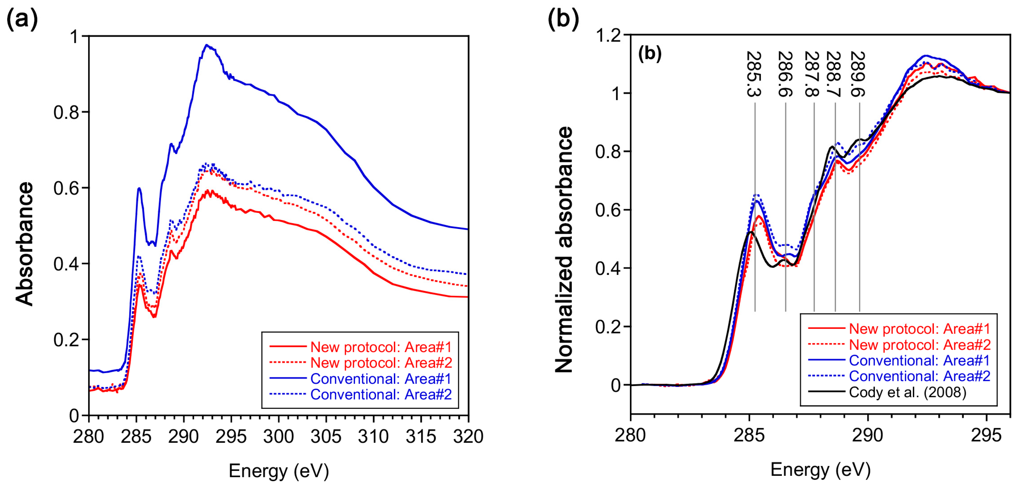
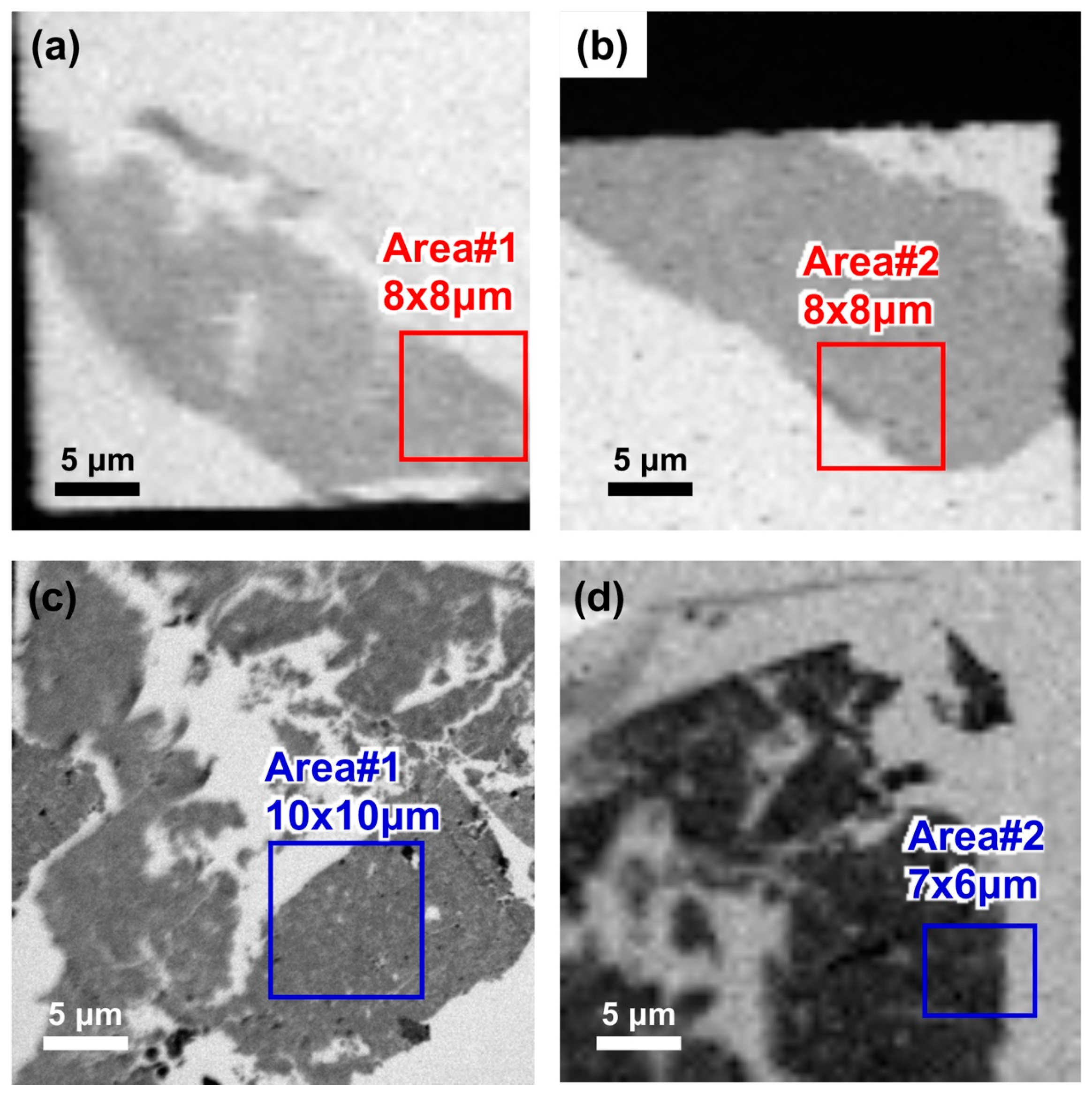
3.9. STXM–XANES Analysis
4. Discussion and Conclusions
Author Contributions
Funding
Acknowledgments
Conflicts of Interest
References
- Bradley, J.P.; Keller, L.; Thomas, K.L.; Vanderwood, T.B. Carbon analyses of IDPs sectioned in sulfur and supported on beryllium films. Lunar Planet. Sci. Conf. 1993, 24, 173–174. [Google Scholar]
- Flynn, G.J.; Keller, L.; Feser, M.; Wirick, S.; Jacobsen, C. The origin of organic matter in the solar system: Evidence from the interplanetary dust particles. Geochim. Cosmochim. Acta 2003, 67, 4791–4806. [Google Scholar] [CrossRef]
- Keller, L.P.; Messenger, S.; Flynn, G.J.; Clemett, S.; Wirick, S.; Jacobsen, C. The nature of molecular cloud material in interplanetary dust. Geochim. Cosmochim. Acta 2004, 68, 2577–2589. [Google Scholar] [CrossRef]
- Cody, G.; Ade, H.; Alexander, C.M.O.; Araki, T.; Butterworth, A.; Fleckenstein, H.; Flynn, G.; Gilles, M.K.; Jacobsen, C.; Kilcoyne, A.L.D.; et al. Quantitative organic and light-element analysis of comet 81P/Wild 2 particles using C-, N-, and O-μ-XANES. Meteorit. Planet. Sci. 2008, 43, 353–365. [Google Scholar] [CrossRef]
- Zolensky, M.; Nakamura-Messenger, K.; Rietmeijer, F.; Leroux, H.; Mikouchi, T.; Ohsumi, K.; Simon, S.; Grossman, L.; Stephan, T.; Weisberg, M.; et al. Comparing Wild 2 particles to chondrites and IDPs. Meteorit. Planet. Sci. 2008, 43, 261–272. [Google Scholar] [CrossRef]
- De Gregorio, B.T.; Stroud, R.M.; Nittler, L.R.; Alexander, C.; Kilcoyne, A.L.D.; Zega, T.J. Isotopic anomalies in organic nanoglobules from Comet 81P/Wild 2: Comparison to Murchison nanoglobules and isotopic anomalies induced in terrestrial organics by electron irradiation. Geochim. Cosmochim. Acta 2010, 74, 4454–4470. [Google Scholar] [CrossRef]
- Groopman, E.E.; Nittler, L.R. Correlated XANES, TEM, and NanoSIMS of presolar graphite grains. Geochim. Cosmochim. Acta 2018, 221, 219–236. [Google Scholar] [CrossRef]
- Kebukawa, Y.; Okudaira, K.; Yabuta, H.; Hasegawa, S.; Tabata, M.; Furukawa, Y.; Ito, M.; Nakato, A.; Kilcoyne, A.L.D.; Kobayashi, K.; et al. STXM-XANES analyses of Murchison meteorite samples captured by aerogel after hypervelocity impacts: A potential implication of organic matter degradation for micrometeoroid collection experiments. Geochem. J. 2019, 53, 53–67. [Google Scholar] [CrossRef]
- Bose, M.; Zega, T.J.; Williams, P. Assessment of alteration processes on circumstellar and interstellar grains in Queen Alexandra Range 97416. Earth Planet. Sci. Lett. 2014, 399, 128–138. [Google Scholar] [CrossRef]
- Le Guillou, C.; Brearley, A. Relationships between organics, water and early stages of aqueous alteration in the pristine CR3.0 chondrite MET 00426. Geochim. Cosmochim. Acta 2014, 131, 344–367. [Google Scholar] [CrossRef]
- Le Guillou, C.; Bernard, S.; Brearley, A.; Remusat, L. Evolution of organic matter in Orgueil, Murchison and Renazzo during parent body aqueous alteration: In situ investigations. Geochim. Cosmochim. Acta 2014, 131, 368–392. [Google Scholar] [CrossRef]
- Noguchi, T.; Yabuta, H.; Itoh, S.; Sakamoto, N.; Mitsunari, T.; Okubo, A.; Okazaki, R.; Nakamura, T.; Tachibana, S.; Terada, K.; et al. Variation of mineralogy and organic matter during the early stages of aqueous activity recorded in Antarctic micrometeorites. Geochim. Cosmochim. Acta 2017, 208, 119–144. [Google Scholar] [CrossRef]
- Yabuta, H.; Noguchi, T.; Itoh, S.; Nakamura, T.; Miyake, A.; Tsujimoto, S.; Ohashi, N.; Sakamoto, N.; Hashiguchi, M.; Abe, K.; et al. Formation of an ultracarbonaceous Antarctic micrometeorite through minimum aqueous alteration in a small porous icy body. Geochim. Cosmochim. Acta 2017, 214, 172–190. [Google Scholar] [CrossRef]
- Kebukawa, Y.; Zolensky, M.E.; Ito, M.; Ogawa, N.O.; Takano, Y.; Ohkouchi, N.; Nakato, A.; Suga, H.; Takeichi, Y.; Takahashi, Y.; et al. Primordial organic matter in the xenolithic clast in the Zag H chondrite: Possible relation to D/P asteroids. Geochim. Cosmochim. Acta 2020, 271, 61–77. [Google Scholar] [CrossRef]
- Takeichi, Y.; Inami, N.; Suga, H.; Miyamoto, C.; Ueno, T.; Mase, K.; Takahashi, Y.; Ono, K. Design and performance of a compact scanning transmission X-ray microscope at the Photon Factory. Rev. Sci. Inst. 2016, 87, 013704. [Google Scholar] [CrossRef]
- De Gregorio, B.T.; Sharp, T.G.; Rushdi, A.I.; Simoneit, B.R.T. Bugs or Gunk? Nanoscale Methods for Assessing the Biogenicity of Ancient Microfossils and Organic Matter. In Earliest Life on Earth: Habitats, Environments and Methods of Detection; Springer Science and Business Media LLC: Berlin, Germany, 2010; pp. 239–289. [Google Scholar]
- Fairbrother, F.; Gee, G.; Merrall, G.T. The polymerization of sulfur. J. Polym. Sci. 1955, 16, 459–469. [Google Scholar] [CrossRef]
- Tobolsky, A.V.; Eisenberg, A. Equilibrium Polymerization of Sulfur. J. Am. Chem. Soc. 1959, 81, 780–782. [Google Scholar] [CrossRef]
- Mayer, B. Elemental sulfur. Chem. Rev. 1975, 76, 367–388. [Google Scholar] [CrossRef]
- Kozhevnikov, V.; Payne, W.B.; Olson, J.K.; McDonald, C.L.; Inglefield, C.E. Physical properties of sulfur near the polymerization transition. J. Chem. Phys. 2004, 121, 7379. [Google Scholar] [CrossRef]
- Klement, W. Thermodynamics of the Lambda Transition in Liquid Sulfur. J. Chem. Phys. 1966, 45, 1421. [Google Scholar] [CrossRef]
- Donaldson, A.; Caplin, A.D. Refractive index of molten sulphur. Philos. Mag. B 1985, 52, 185–197. [Google Scholar] [CrossRef]
- Cody, G.; Alexander, C.; Yabuta, H.; Kilcoyne, A.L.D.; Araki, T.; Ade, H.; Dera, P.; Fogel, M.; Militzer, B.; Mysen, B. Organic thermometry for chondritic parent bodies. Earth Planet. Sci. Lett. 2008, 272, 446–455. [Google Scholar] [CrossRef]
- Kebukawa, Y.; Nakashima, S.; Zolensky, M.E. Kinetics of organic matter degradation in the Murchison meteorite for the evaluation of parent-body temperature history. Meteorit. Planet. Sci. 2010, 45, 99–113. [Google Scholar] [CrossRef]


© 2020 by the authors. Licensee MDPI, Basel, Switzerland. This article is an open access article distributed under the terms and conditions of the Creative Commons Attribution (CC BY) license (http://creativecommons.org/licenses/by/4.0/).
Share and Cite
Noguchi, T.; Takase, M.; Matsumoto, R.; Kebukawa, Y.; Suga, H.; Kondo, M.; Takahashi, Y.; Takeichi, Y.; Yabuta, H. An Another Protocol to Make Sulfur Embedded Ultrathin Sections of Extraterrestrial Small Samples. Life 2020, 10, 135. https://doi.org/10.3390/life10080135
Noguchi T, Takase M, Matsumoto R, Kebukawa Y, Suga H, Kondo M, Takahashi Y, Takeichi Y, Yabuta H. An Another Protocol to Make Sulfur Embedded Ultrathin Sections of Extraterrestrial Small Samples. Life. 2020; 10(8):135. https://doi.org/10.3390/life10080135
Chicago/Turabian StyleNoguchi, Takaaki, Minako Takase, Rikako Matsumoto, Yoko Kebukawa, Hiroki Suga, Masashi Kondo, Yoshio Takahashi, Yasuo Takeichi, and Hikaru Yabuta. 2020. "An Another Protocol to Make Sulfur Embedded Ultrathin Sections of Extraterrestrial Small Samples" Life 10, no. 8: 135. https://doi.org/10.3390/life10080135
APA StyleNoguchi, T., Takase, M., Matsumoto, R., Kebukawa, Y., Suga, H., Kondo, M., Takahashi, Y., Takeichi, Y., & Yabuta, H. (2020). An Another Protocol to Make Sulfur Embedded Ultrathin Sections of Extraterrestrial Small Samples. Life, 10(8), 135. https://doi.org/10.3390/life10080135