Author Contributions
Conceptualization, Y.-C.H.; methodology, L.-W.T. and T.-S.H.; software, L.-W.T. and T.-S.H.; validation, L.-W.T. and T.-S.H.; formal analysis, Y.-C.H.; investigation, L.-W.T. and T.-S.H.; resources, Y.-C.H.; data curation, L.-W.T. and T.-S.H.; writing—original draft preparation, L.-W.T., T.-S.H., and Y.-C.H.; writing—review and editing, Y.-C.H.; visualization, L.-W.T. and T.-S.H.; supervision, Y.-C.H.; project administration, Y.-C.H.; funding acquisition, Y.-C.H. All authors have read and agreed to the published version of the manuscript.
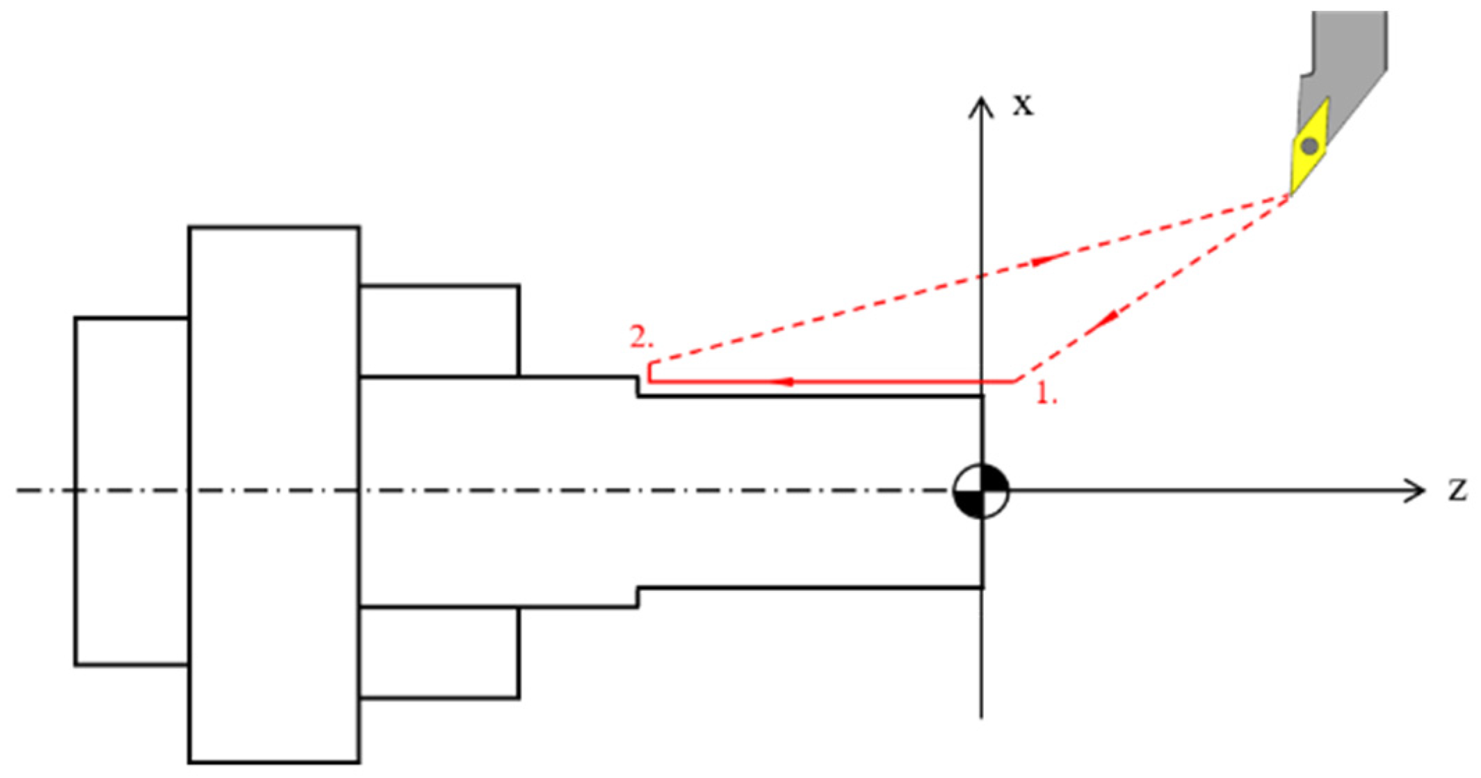
Figure 1.
The schematic diagram of the cutting force in longitudinal turning.
Figure 1.
The schematic diagram of the cutting force in longitudinal turning.
Figure 2.
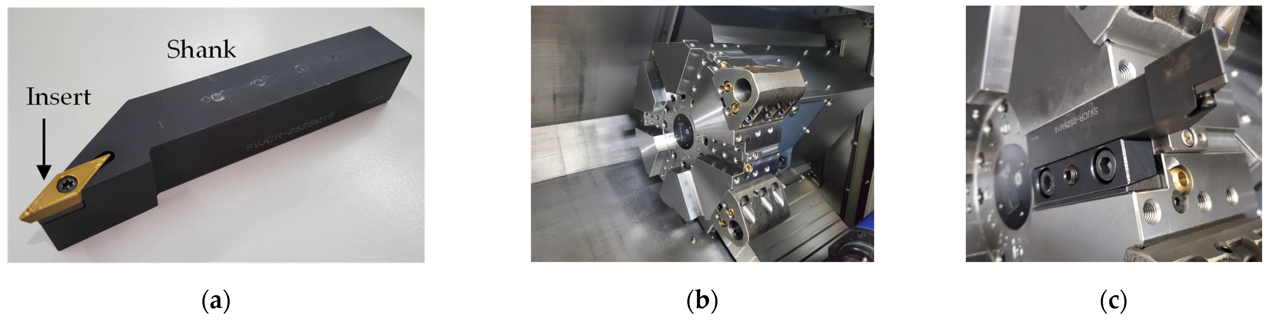
The proposed smart tool holder is designed for: (a) the standard turning tool, model: SVJCR-2525M16; (b) the tool turret of the Tongtai TS-85 CNC bedroom lathe; and (c) the turning tool clamped on the tool turret.
Figure 2.
The proposed smart tool holder is designed for: (a) the standard turning tool, model: SVJCR-2525M16; (b) the tool turret of the Tongtai TS-85 CNC bedroom lathe; and (c) the turning tool clamped on the tool turret.
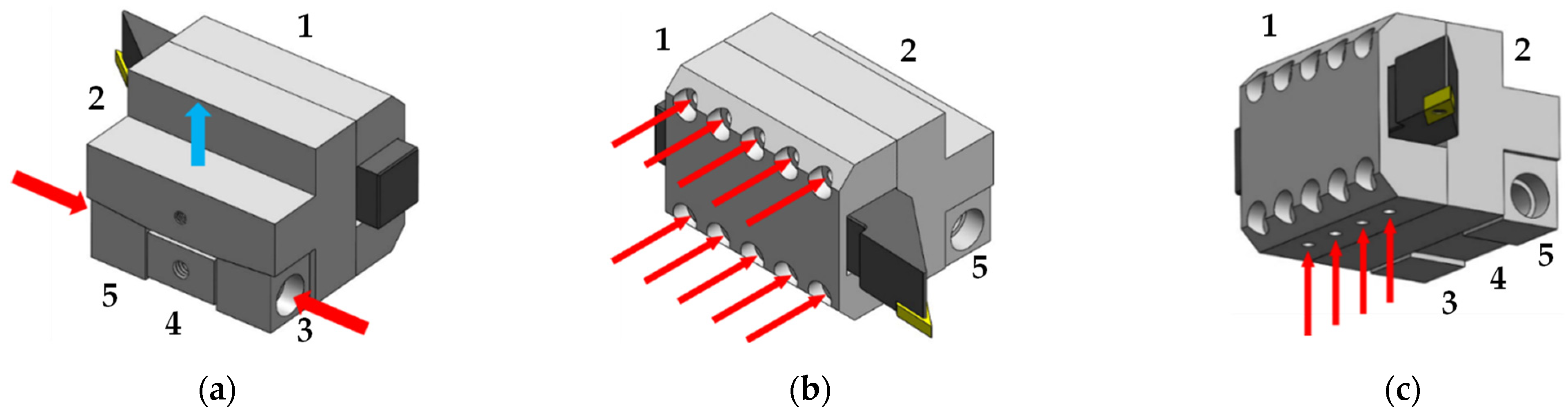
Figure 3.
The structure of the smart tool holder consists of: (a) the five parts of the smart tool holder, including the front cover (part 1), the rear cover (part 2), and the wedge, composed of parts 3 to 5; (b) parts 1 and 2, which are assembled by ten M6 hexagon socket screws; and (c) the clamping tightness of the turning tool, which is adjusted by four M6 set screws.
Figure 4.
The stress field of the smart tool holder subject to the cutting force based on finite element simulation: (a) the fixed boundaries being shown on the blue surfaces; (b) the stress field of the combination of the turning tool and the smart tool holder; and (c) the backside and front-side views of the stress field of the smart tool holder.
Figure 5.
The completed structure of the smart tool holder: (a) Part 1 is the front cover; (b) part 2 is the rear cover; (c) parts 3 to 5 form the wedge through which the smart tool holder is installed on the turret; (d) the smart tool holder clamping the turning tool; and (e) the assembly of the smart tool holder and turning tool installed on the turret through the wedge.
Figure 6.
The force sensor device: (a) the flexible force sensor foil, and (b) the schematic diagram of the flexible force sensor foil connecting to a data acquisition toolbox. The data acquisition toolbox transmits data to the personal computer next to the machine tool through Bluetooth.
Figure 6.
The force sensor device: (a) the flexible force sensor foil, and (b) the schematic diagram of the flexible force sensor foil connecting to a data acquisition toolbox. The data acquisition toolbox transmits data to the personal computer next to the machine tool through Bluetooth.
Figure 7.
The determination process of the position of the film force sensor: (a) the schematic diagram of the longitudinal coordinate of the turning tool; (b) the stress distribution at the bottom surface of the turning tool along its longitudinal axis when subject to cutting force; (c) the stress difference of (b); (d) the bonding position of the film force sensor.
Figure 8.
The completed smart tool holder that is clamping a turning tool. The smart tool holder includes the tool holder structure, the film force sensor, and the wireless data acquisition unit.
Figure 8.
The completed smart tool holder that is clamping a turning tool. The smart tool holder includes the tool holder structure, the film force sensor, and the wireless data acquisition unit.
Figure 9.
The static load test of the smart tool holder: (a) the turning tool and smart tool holder clamped on the optical table in order to simulate their installation on the turret; and (b) the experiment setup of the static load test.
Figure 9.
The static load test of the smart tool holder: (a) the turning tool and smart tool holder clamped on the optical table in order to simulate their installation on the turret; and (b) the experiment setup of the static load test.
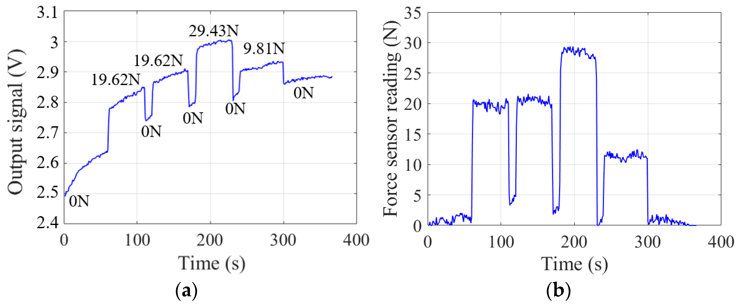
Figure 10.
The output signal of the film force sensor under variety cutting force magnitudes.
Figure 10.
The output signal of the film force sensor under variety cutting force magnitudes.
Figure 11.
The schematic diagram of Artificial Neural Network: (a) a neuron; and (b) the artificial neural network.
Figure 11.
The schematic diagram of Artificial Neural Network: (a) a neuron; and (b) the artificial neural network.
Figure 12.
The hyperbolic tangent function.
Figure 12.
The hyperbolic tangent function.
Figure 13.
The learning curve of the ANN model.
Figure 13.
The learning curve of the ANN model.
Figure 14.
The external validation of the ANN model: (a) the raw data of the external validation set; and (b) the force sensor reading of the smart tool holder with ANN calibration.
Figure 14.
The external validation of the ANN model: (a) the raw data of the external validation set; and (b) the force sensor reading of the smart tool holder with ANN calibration.
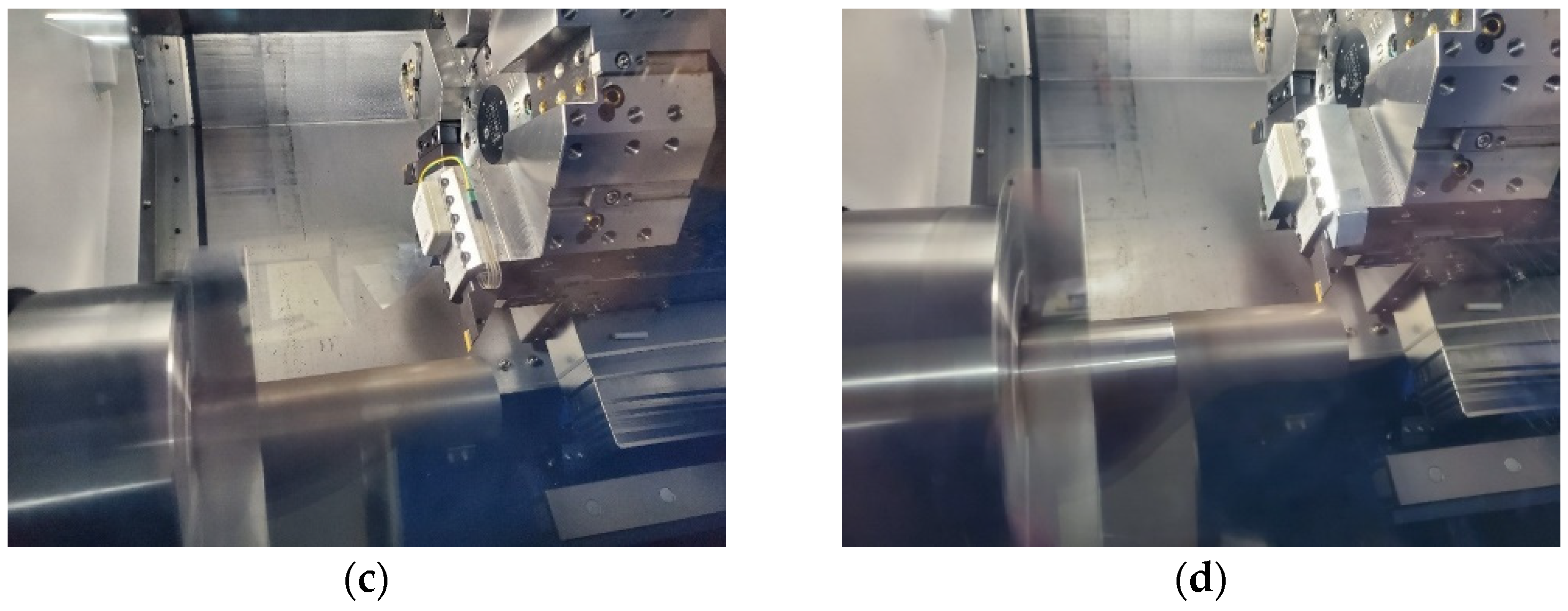
Figure 15.
The turning experiment setup: (a) Tongtai TS-85 bedroom CNC lathe; (b) the workpiece, smart tool holder, and the turning tool installed on the machine tool, and a personal computer next the machine tool; (c) the bare smart tool holder; and (d) the smart tool holder with aluminum protective shielding.
Figure 16.
The schematic diagram of outer diameter turning.
Figure 16.
The schematic diagram of outer diameter turning.
Figure 17.
The force sensor readings of the smart tool holder at the working condition of constant feed rate (f) and cutting depth (ap): (a) f = 0.1 mm/rev, ap = 0.1 mm; (b) f = 0.1 mm/rev, ap = 0.3; (c) f = 0.2 mm/rev, ap = 0.1 mm; and (d) f = 0.2 mm/rev, ap = 0.3 mm. The spindle rotates at 500 rpm and the cut length is 90 mm.
Figure 18.
The force sensor readings of the smart tool holder at the working condition of varying feed rate (f). The cutting length is 90 mm, f is changed every 30 mm in the order of 0.1 mm/rev, 0.15 mm/rev, and 0.2 mm/rev, and the constant cutting depth is, respectively, (a) ap = 0.1 mm; and (b) ap = 0.3 mm. The spindle rotates at 500 rpm.
Figure 19.
The variation of the ratio of the cutting force (Fc) to the depth of cut (ap) with respect to the feed rate (f).
Figure 19.
The variation of the ratio of the cutting force (Fc) to the depth of cut (ap) with respect to the feed rate (f).
Figure 20.
The comparison of measured and calculated cutting force in the fine turning of low carbon steel S15C.
Figure 20.
The comparison of measured and calculated cutting force in the fine turning of low carbon steel S15C.
Table 1.
The specification of the model SVJCR-2525M16 turning tool and the model VCMT160404HQ insert.
Table 1.
The specification of the model SVJCR-2525M16 turning tool and the model VCMT160404HQ insert.
| Model SVJCR-2525M16 turning tool |
| Order No. | H | B | LF | LH | WF | Cutting-edge angle (κ) | Rake angle (γ) |
| SVJCR-2525M16 | 25 mm | 25 mm | 150 mm | 38 mm | 32 mm | 93° | 0° |
![Machines 09 00190 i001]() |
| Model VCMT160404HQ insert |
| Style: VMCT | Size: 331 | Chipbreaker: HQ | ![Machines 09 00190 i002]() |
| Grade: CA525 | Thickness (S): 4.76 mm | Corner radius (RE): 0.4 mm |
| Inscribe circle (IC): 9.53 mm | Hole diameter (D1): 4.4 mm | Rake: Positive |
| Relief angle: 7° | Include angle: 35° | Number of cutting edges: 2 |
| Material: Carbide | Material grade: Micro columnar | Coating process: CVD |
| Coating composition: TiCn/Al2O3/TiN | Insert hand: Neutral |
| Primary workpiece: Steel | Shape: Diamond | Insert holding method: Screw | Series: CA5-series |
| Usage classification: Light interruption | Cutting range: Finishing medium |
| Application: External turning, copying, facing, undercutting, profiling, internal facing, back boring. |
Table 2.
The material and geometrical properties of the low carbon steel JIS S15C workpiece.
Table 2.
The material and geometrical properties of the low carbon steel JIS S15C workpiece.
| Composition in wt% | C | Mn | P | S | Si |
| 0.13–0.18 | 0.3–0.6 | ≤0.03 | ≤0.035 | 0.15–0.35 |
| Material property | Yield strength | Tensile strength | Elongation | Hardness HB |
| ≥235 N/mm2 | ≥370 N/mm2 | ≥30% | 111–167 (Normal) | 111–149 (Anneal) |
| Geometrical property | Geometry | Length | Diameter |
| Rod | 200 mm | 60 mm |
Table 3.
The parameters related to the cutting force calculation through Kienzle model.
Table 3.
The parameters related to the cutting force calculation through Kienzle model.
| Material parameters, JIS S15C | Basic specific cutting force, kc1,1 (N/mm2) | Material constant, z |
| 1820 [18] | 0.22 |
| Tool parameters | Rake angle, γ | Cutting edge angle, κ |
| 0° | 93° |
| Constant machining parameters | Spindle speed (rpm) | Cutting speed (m/min) |
| 500 | 94.25 |
| Correction coefficients | Kγ | Kv | Kst | Kver |
| 1.06 | 1.00 | 1.00 | 1.00 |
| Variable machining parameters | Depth of cut, ap (mm) | 0.1 | 0.3 |
| Feed rate, f (mm/rev) | 0.10 | 0.15 | 0.20 | 0.10 | 0.15 | 0.20 |
| Specific cutting force, kc (N/mm2), calculated by Equation (4) | 3202 | 2929 | 2749 | 3202 | 2929 | 2749 |
| Cutting force, Fc (N) | 32.02 | 43.93 | 54.98 | 96.06 | 131.80 | 164.94 |
Table 4.
The specification of the force sensor device.
Table 4.
The specification of the force sensor device.
| Item | Value |
|---|
| Diameter of sensing area | 10 mm |
| Maximum sensing area | 78.5 mm2 |
| PET foil thickness | 0.25 mm |
| Maximum sensing force | 245 N |
| Minimum sensing dimension | 0.5 mm × 0.5 mm |
| Power supply | Type +5V, Type 5 mA (max.) |
| Linearity | <±3% |
| Repeatability | <±2.5% Full sensing range |
| Hysteresis | <±4.5% Full sensing range |
| Drift | <5% Logarithmic time scale |
| Response time | <5 μs |
| Sampling rate | 100 Hz |
Table 5.
The results of the cross-interference test.
Table 5.
The results of the cross-interference test.
| Ff (N) | 9.81 | 19.62 | 29.43 | 39.24 | 49.05 | 58.86 | 68.67 | 78.48 | 88.29 | 98.10 | 107.91 | 117.72 |
| Force sensor reading (N) | 0.00 | 0.00 | 0.00 | 0.00 | 0.21 | 3.68 | 2.38 | 1.93 | 0.79 | 0.96 | 2.12 | 0.99 |
| XI% * | 0.00 | 0.00 | 0.00 | 0.00 | 0.43 | 6.25 | 3.47 | 2.46 | 0.89 | 0.98 | 1.96 | 0.84 |
| MXI% * | 1.44 |
| Fp (N) | 9.81 | 19.62 | 29.43 | 39.24 | 49.05 | 58.86 | 68.67 | 78.48 | 88.29 | 98.10 | 107.91 | 117.72 |
| Force sensor reading (N) | 0.60 | 0.20 | 0.00 | 0.00 | 0.51 | 0.87 | 0.91 | 1.32 | 1.65 | 2.16 | 2.37 | 2.41 |
| XI% | 6.12 | 1.02 | 0.00 | 0.00 | 1.04 | 1.48 | 1.33 | 1.68 | 1.87 | 2.20 | 2.20 | 2.05 |
| MXI% | 1.75 |
Table 6.
The error test of the major cutting force measurement.
Table 6.
The error test of the major cutting force measurement.
| Fc (N) | 9.81 | 19.62 | 29.43 | 39.24 | 49.05 | 58.86 | 68.67 | 78.48 | 88.29 | 98.10 | 107.91 | 117.72 |
| Force sensor reading (N) | 11.06 | 21.01 | 31.09 | 40.40 | 49.42 | 59.07 | 68.51 | 78.59 | 89.73 | 97.45 | 106.79 | 117.66 |
| E% * | 12.74 | 7.08 | 5.64 | 2.96 | 0.75 | 0.36 | 0.23 | 0.14 | 1.63 | 0.66 | 1.04 | 0.05 |
| ME% * | 2.77 |
Table 7.
The comparison of the readings of the smart tool holder with the theoretical values.
Table 7.
The comparison of the readings of the smart tool holder with the theoretical values.
| ap (mm) | f (mm/rev) | kc (N/mm2) | | | | | |Deviation|% |
|---|
| 0.1 | 0.1 | 3202 | 32.02 | 320.2 | 24.92 | 249.2 | 22.17 |
| 0.15 | 2929 | 43.93 | 439.3 | 31.98 | 319.8 | 27.21 |
| 0.2 | 2749 | 54.98 | 549.8 | 40.91 | 409.1 | 25.59 |
| 0.3 | 0.1 | 3202 | 96.06 | 320.2 | 68.18 | 227.3 | 29.02 |
| 0.15 | 2929 | 131.80 | 439.3 | 100.75 | 335.8 | 23.56 |
| 0.2 | 2749 | 164.94 | 549.8 | 130.18 | 433.9 | 21.07 |
| | | | | | Mean deviation | 24.77 |
| | | | | | Standard deviation, σ | 3.05 |
Table 8.
The fine turning parameters of low carbon steel S15C and the cutting forces, wherein the nose radius of insert (re) is 0.4 mm, the cutting edge angle (κ) is 1.6232 rad (93°).
Table 8.
The fine turning parameters of low carbon steel S15C and the cutting forces, wherein the nose radius of insert (re) is 0.4 mm, the cutting edge angle (κ) is 1.6232 rad (93°).
| ap (mm) | f (mm) | Fc′ (N) 1 | beq (mm) 2 | heq (mm) 3 | kc (N/mm2) 4 | log(beq) | log(heq) | log(kc) | Fc (N) 5 | |Force Deviation|% 6 |
|---|
| 0.1 | 0.1 | 24.92 | 0.3780 | 0.0265 | 2492 | −0.4225 | −1.5775 | 3.3965 | 23.41 | 6.47 |
| 0.1 | 0.15 | 31.98 | 0.4033 | 0.0372 | 2132 | −0.3943 | −1.4296 | 3.3288 | 32.98 | 3.04 |
| 0.1 | 0.2 | 40.91 | 0.4290 | 0.0466 | 2046 | −0.3676 | −1.3314 | 3.3108 | 42.56 | 3.89 |
| 0.3 | 0.1 | 68.18 | 0.5783 | 0.0519 | 2273 | −0.2379 | −1.2850 | 3.3565 | 71.34 | 4.43 |
| 0.3 | 0.15 | 100.75 | 0.6036 | 0.0746 | 2239 | −0.2192 | −1.1275 | 3.3500 | 98.91 | 1.86 |
| 0.3 | 0.2 | 130.18 | 0.6292 | 0.0954 | 2170 | −0.2012 | −1.0207 | 3.3364 | 125.76 | 3.51 |
| Mean value of |Force deviation|% | 3.87 |
| Standard deviation of |Force deviation|% | 1.55 |


