Article

A Vibration Suppression Method for the Multistage Rotor of an Aero-Engine Based on Assembly Optimization

1
Centre of Ultra-Precision Optoelectronic Instrument Engineering, Harbin Institute of Technology, Harbin 150080, China
2
Key Lab of Ultra-Precision Intelligent Instrumentation, Harbin Institute of Technology, Ministry of Industry and Information Technology, Harbin 150080, China
*
Author to whom correspondence should be addressed.
Machines 2021, 9(9), 189; https://doi.org/10.3390/machines9090189
Submission received: 28 July 2021 / Revised: 25 August 2021 / Accepted: 3 September 2021 / Published: 5 September 2021
(This article belongs to the Section Machines Testing and Maintenance)

Abstract

:
The assembly quality of the multistage rotor is an essential factor affecting its vibration level. The existing optimization methods for the assembly angles of the rotors at each stage can ensure the concentricity and unbalance meet the requirements, but it cannot directly ensure its vibration responses meet the indexes. Therefore, in this study, we first derived the excitation formulas of the geometric and mass eccentricities on the multistage rotor and introduced it into the dynamics model of the multistage rotor system. Then, the coordinate transfer model of the geometric and mass eccentricities errors, including assembly angles of the rotors at all stages, was established. Moreover, the mathematical relationship between the assembly angles of the rotors at all stages and the nodal vibration responses was established by combining the error transfer model with the dynamics model of the multistage rotor system. Furthermore, an optimization function was developed, which takes the assembly angles as the optimization variables and the maximum vibration velocity at the bearings as the optimization objective. Finally, a simplified four-stage high-pressure rotor system was assembled according to the optimal assembly angles calculated in the simulations. The experimental results showed that the maximum vibration velocity at the bearings under the optimal assembly was reduced by 69.6% and 45.5% compared with that under the worst assembly and default assembly. The assembly optimization method proposed in this study has a significant effect on the vibration suppression of the multistage rotor of an aero-engine.

1. Introduction

Vibration overrun is the main reason for the failure or damage to the rotating machinery such as aero-engine and gas turbines with multistage rotors [1,2]. Rotor misalignment and unbalance are the two most common factors causing the vibration on the multistage rotor system [3,4,5]. Rotor misalignment is the geometric eccentricity caused by the accumulation of the machining errors of each single-stage rotor after assembly stage-by-stage. This accumulative error will also cause each single-stage rotor to deviate from its nominal assembly axis and form mass eccentricity, resulting in unbalance. Therefore, rotor misalignment and unbalance often exist simultaneously, and the multistage rotor of an aero-engine often needs to be repeatedly balanced and disassembled to meet vibration indexes [6,7]. Assembly optimization is to search the optimal assembly angles of the rotors at all stages to achieve the maximum vibration suppression of a multistage rotor without secondary repair. It can significantly improve the qualification rate of the one-time assembly and reduce the costs of manufacturing and test-run for an aero-engine.
Hussain et al. [8] first proposed to reduce the vibration on the stacked multistage rotor system by assembly optimization. They put forward a linear-assembly method, which means that the appropriate assembly angles of each rotor of a multistage rotor are selected to make the assembly axis as close as possible to a straight line in the assembly process. This method has the potential to reduce the vibration caused by rotor misalignment. Then, for 2-D axisymmetric rotors, Hussain et al. [9] realized the optimization of linear-assembly by minimizing the root mean square of the radial runout errors of the assembly rabbets of each rotor. Furthermore, Hussain et al. [10] proposed a method to minimize the inclination angles of the assembly rabbets of each rotor, which also aims to avoid transitional bending of the assembly axis. Zhang et al. [11] used the error transfer theory to deduce the geometric cumulative eccentricity error after assembly and used this error to represent the bending degree of the assembly axis. Zhang et al. [12] also put forward a concept of parallel-assembly: minimizing the parallelism errors of the assembly rabbets of each rotor during assembly. Comparing the linear-assembly method showed that this method could also make the assembly axis not appear too large a deflection. Moreover, Zhang et al. [13] put forward another concept of assembly optimization step-by-step, that is, for the rotors at each stage, the geometric eccentricity error of the rotor at the next stage is optimized based on the current assembly axis. In addition, Zhang et al. [14] deduced the geometric eccentricity error of the multistage rotor in [11] as a probability density function, calculated the cumulative eccentricity error under all assembly conditions, and then judged the maximum and minimum curvature of the assembly axis.
In [8,9,10,11,12,13,14], the tolerance ranges of the assembly rabbets of each rotor were given, the geometric eccentricity errors of a multistage rotor were calculated by the Monte Carlo simulation method under all possible matching relations of the assembly angles of each rotor. They could obtain the distributions of the cumulative assembly errors and the maximum and minimum values of that. However, they could not directly give the optimal assembly angles of each rotor.
Sun et al. [15] analyzed the primary and secondary relationship of the positioning datum of the rotor at different stages, transformed parts of the parallel dimension chain into the series dimension chain, established a more accurate Jacobian error transfer model, and applied it to calculate the cumulative eccentric errors. However, Sun et al. [16] pointed out that the dimension of the Jacobi matrix changes with the number of parts, which is not suitable for fast modelling. Then, they constructed a deviation propagation analysis model by homogeneous coordinate transformation. Wang et al. [17] substituted the measured orientation and positioning errors of the assembly rabbets of each rotor into the above transfer model and calculated the assembly angles of the rotors at all stages under the condition of minimum eccentricity error. They verified the optimization effect of the eccentricity error by experiments. Sun et al. [18] further combined the above transfer model with a neural network to intelligently select the optimal assembly angles of each rotor under the condition of minimizing geometric eccentricity error. The above studies only focused on optimizing rotor misalignment of multistage rotors. However, the unbalance caused by mass eccentricity is also an essential factor leading to excessive vibration on the multistage rotor. Ganine et al. [19] proposed a new parametric model order reduction algorithm for vibration analysis of rotor assemblies with variations in geometry induced by disk misalignment. However, their study focused on the dynamics model order reduction rather than the vibration suppression through optimizing the assembly angles.
Liu et al. [20] assumed that the material distribution of the rotors at all stages is uniform, estimated the mass eccentricity error through the geometric deviation of each rotor, and substituted it into the model in [17] to calculate the minimum unbalance of a three-stage rotor under all assembly possibilities, and gave the corresponding assembly angles of each rotor. Piskin et al. [21] realized the weight matching of the blades in the circumferential direction of the rotors at all stages by using an ant colony algorithm. Chen et al. [22] pointed out that the assembly datum for unbalance optimization should not be equal to that in optimization for geometric eccentricity error and proposed an optimization method for unbalance based on orientation varying-axis. Sun et al. [23] proposed an assembly optimization method for the dual objectives of concentricity and unbalance of a multistage rotor, making the concentricity and unbalance simultaneously approach their respective optimal solutions to the greatest extent. Nevertheless, for the genuine multistage rotors, the assembly angles of each rotor are discontinuous, which requires the assembly screw holes of each rotor to be aligned first and then selected. To solve this problem, Chen et al. [24] introduced the calibrated angles of screw holes into the error transfer model and proposed a reverse assembly method, which decomposed the assembly process of adjacent rotors into three steps: alignment, rotation, and translation. Chen et al. [25] further transformed the continuous variables of the assembly angles of each rotor into the discrete variables composed of assembly screw holes and obtained the corresponding optimal relationship of the screw holes directly without secondary calculation. The influence of the geometric measurement errors on the stability of assembly optimization was also investigated by the Monte Carlo method.
All the above studies aimed to reduce the misalignment and unbalance in the stacked multistage rotor by optimizing the assembly angles of each single-stage rotor. The ultimate goal is to reduce the vibration on the multistage rotor to the greatest extent during the pre-assembly stage. However, these studies have not established a direct relationship between the assembly angles of the rotors at all stages and the rotor vibration in theory. Although the optimization of the misalignment and unbalance can undoubtedly reduce the vibration to a certain extent from mechanical common sense. However, from the dynamics perspective, the vibration of different nodes on the rotor may be different under the same concentricity and unbalance of a multistage rotor. If the assembly optimization aims to reduce vibration, the vibration of the critical node caused by geometric and mass eccentricities should be taken as the optimization objective. Therefore, we summarized the existing problems in the field of assembly optimization into the following two aspects:
  • The mathematical relationship between the assembly angles of the rotors at all stages and the vibration responses should be established;
  • The vibration responses of the critical nodes on the rotor should be taken as the optimization objective to calculate the optimal assembly angles.
To solve the above problems, firstly, in Section 2.1, we developed a single-node dynamics model for a rotor with geometric and mass eccentricities, derived the corresponding dynamics differential equations of the elastic shaft element in Section 2.2. Moreover, in Section 2.3, we established a homogeneous coordinate transfer model of the geometric and mass eccentricities errors. Furthermore, in Section 2.4, we combined the coordinate transfer model with the rotor dynamics model to build a mathematical relationship between the assembly angles of the rotors at all stages and the nodal vibration responses. Then, the solution method of the nodal vibration responses on a multistage rotor system was introduced in Section 2.5. The objectives and variables in assembly optimization were defined in Section 2.6. Finally, a simplified four-stage high-pressure rotor system was assembled according to the optimal assembly angles calculated in the simulations. The experimental results showed that the assembly optimization method proposed in this study has a significant vibration suppression effect on multistage rotor system.

2. Methods

2.1. Single-Node Dynamics Model for a Rotor with Geometric and Mass Eccentricities

A single-node dynamics model for a rotor with geometric and mass eccentricities is shown in Figure 1. M is the center of mass of the single-disc rotor, and the mass of that is m. ε refers to the disc’s mass eccentricity, and the angle between it and the horizontal direction is φε. Due to the initial bending of the rotating shaft, the geometric center of the disc deviated from the rotating center O and reached point O0. O1 is the geometric center of the disc after the rotation of the shaft. rs is the initial geometric eccentricity of the center of the disc, and the angle between it and the horizontal direction is φs. r is the displacement vector of the center of the disc, and the angle between it and the horizontal direction is φr. rd is the dynamic response vector of the center of the disc when the rotor is rotating. p is the displacement vector of the center of mass of the disc. k and c are the stiffness and damping coefficient of the shaft, respectively, and the mass of that is neglected.
According to the balanced relationship among the inertia force, the damping force and the elastic force, the dynamics differential equation of the geometric center of the disc can be expressed as in Equation (1):
m p ¨ + c r ˙ + k r d = 0 .
From the geometric relationship in Figure 1, we can obtained Equation (2):
p = r + ε r d = r r s .
Equation (3) can be obtained by substituting p and rd into Equation (1):
m r ¨ + c r ˙ + k r = k r s m ε ¨ ,
where r, rs and ε can be expressed as plural forms in Equation (4):
r = r exp i ω t + φ r = r cos ω t + φ r + j r sin ω t + φ r = x r + j y r r s = r s exp i ω t + φ s = r s cos ω t + φ s + r s r sin ω t + φ s = x s + j y s ε = ε exp i ω t + φ ε = ε cos ω t + φ ε + ε sin ω t + φ ε = x ε + j y ε .
Then, by substituting Equation (4) into Equation (2), the single-node dynamics differential equation can be obtained as follows:
m x ¨ r + c x ˙ r + k x r = k x s + m ω 2 x ε m y ¨ r + c y ˙ r + k y r = k y s + m ω 2 y ε ,
where kxs and kys are the nodal excitation forces caused by the geometric eccentricity, and 2xε and 2yε are the nodal excitation forces caused by mass eccentricity.

2.2. Dynamics Model of the Shaft Element of a Rotor

The rotor system can be divided into a finite element model composed of several shaft elements and nodes, and the dynamics differential equation of a single Timoshenko-beam element can be established as follows:
M e n 0 0 M e n q ¨ e n + ω 0 G e n G e n 0 + C e n 0 0 C e n q ˙ e n + K e n 0 0 K e n q e n = R e n + Q e n ,
where {qen} = {xn,θyn, yn, −θxn, xn+1, θy(n+1), yn+1, −θx(n+1)}T is the displacement vector of the nth shaft element. The vectors {Ren} and {Qen} denote the excitation forces acting on the shaft element due to the geometric and mass eccentricities, respectively, as shown in Equation (7):
R e n = K e n 0 0 K e n F n Q e n = ω 2 m n P n ,
where {Fn} is the displacement vector of the geometric eccentricity, and {Pn} is that of mass eccentricity. mn refers to the mass of each rotor. Here, the mass-radius product of Pn and mn can be replaced by unUn, which refers to the product of the unbalanced mass un and its action radius Un. The stiffness matrix Ken of the single-node was presented by Genta et al. [26] as follows:
K e n = E I d n l n 3 1 + χ n 12 6 l n 12 6 l n 4 + χ n l n 2 6 l n 2 χ n l n 2 12 6 l n s y m m 4 + χ n l n 2 ,
where E is the Elastic modulus of the rotor, and ln is the length of the element. Idn is the diameter moment of inertia of the circular section of the shaft element, which can be expressed as in Equation (9):
I d n = π D n 4 d n 4 64 ,
where Dn and dn are the outer and inner diameter of the shaft element, respectively. χn is the dimensionless stiffness, as shown in Equation (10):
χ n = 12 E n I d n G n A n l n 2 κ n ,
where Gn is the shear modulus, and An is the cross-sectional area of the element as shown in Equation (11). κn is the shear factor as shown in Equation (12):
A n = π D n 2 d n 2 4 ,
κ n = 6 1 + v n 2 7 + 12 v n + 4 v n 2 ,
where vn is Poisson’s ratio. The single-node moving inertia matrix can be expressed as in Equation (13):
M T n = ρ n A n E n l n 420 1 + χ n 2 t 1 l n t 2 t 3 l n t 4 l n 2 t 5 l n t 4 l n 2 t 6 t 1 l n t 2 s y m m l n 2 t 5 .
The single-node rotational inertia matrix can be expressed as in Equation (14):
M R n = ρ n I d n 30 l n 1 + χ n 2 t 7 l n t 8 t 7 l n t 8 l n 2 t 9 l n t 8 l n 2 t 10 t 7 l n t 8 s y m m l n 2 t 9 ,
where the expressions of t1~t2 are presented in Equation (15):
t 1 = 156 + 294 χ n + 140 χ n 2 t 2 = 22 + 38.5 χ n + 17.5 χ n 2 t 3 = 54 + 126 χ n + 70 χ n 2 t 4 = 13 + 31.5 χ n + 17.5 χ n 2 t 5 = 4 + 7 χ n + 3.5 χ n 2 t 6 = 3 + 7 χ n + 3.5 χ n 2 t 7 = 36 t 8 = 3 15 χ n t 9 = 4 + 5 χ n + 10 χ n 2 t 10 = 1 + 5 χ n 5 χ n 2 .
The single-node global mass matrix can be obtained by Equation (16):
M e n = M T n + M R n .
Gen is the single-node gyro matrix, which is equal to 2MRn. Cen is the single-node damping matrix, and the hysteretic damping model is employed (Cen = ηKen, η = 0.001) [27].

2.3. Error Transfer Model of the Geometric and Mass Eccentricities

2.3.1. Coordinate Transfer

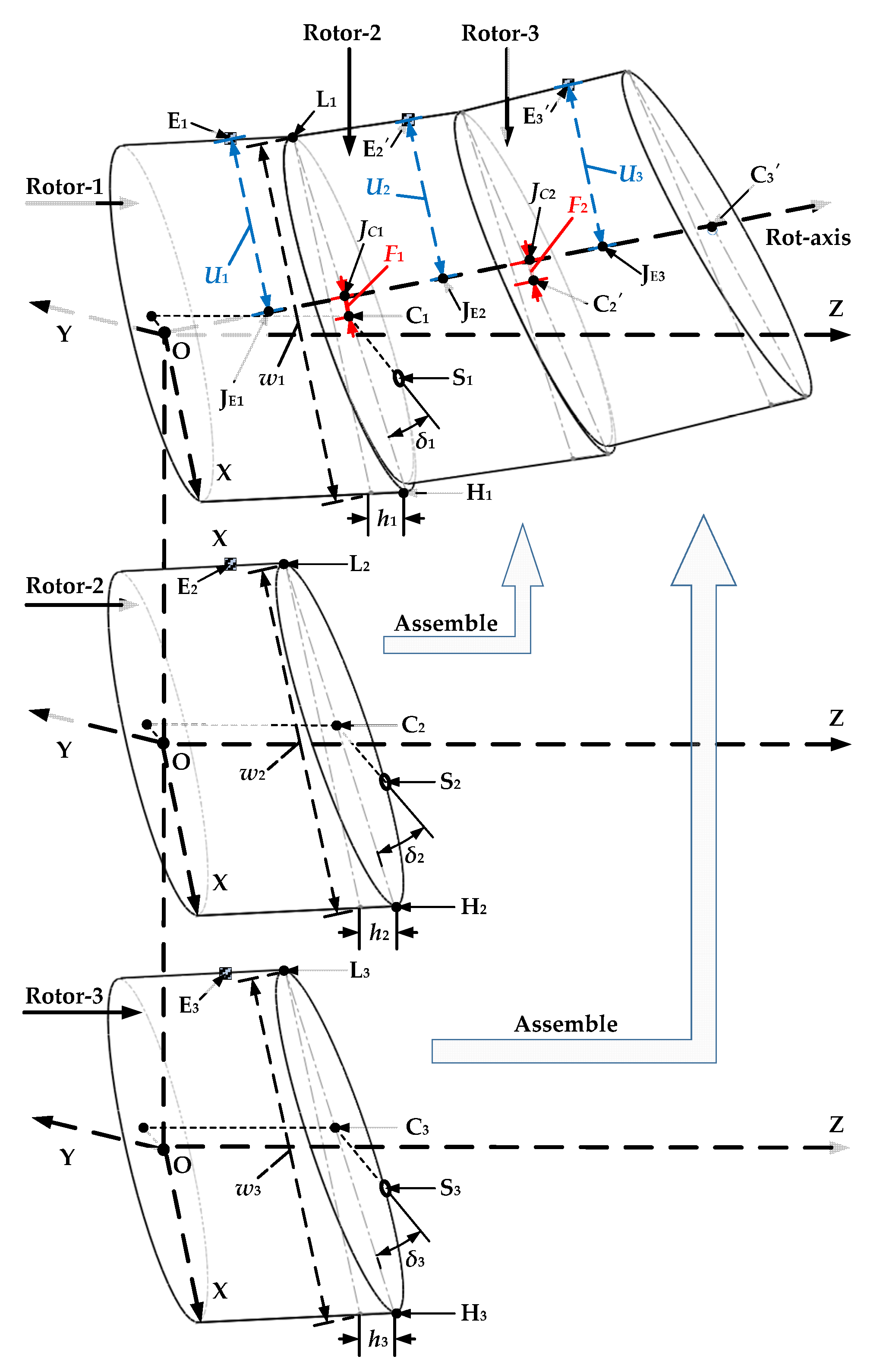
A multistage rotor is assembled step-by-step through the assembly rabbets of each single-stage rotor. In the assembly process, the machining error of the assembly rabbets will make the rotors at each stage deviate from their ideal assembly position and then form the geometric and mass eccentricities. In actuality, the transfer of the eccentricity errors is equivalent to transferring the coordinates of points in the rotor. If the coordinate transfer of each point in the rigid rotor during assembly is known, we can calculate the geometric and mass eccentricities errors after assembly. Figure 2 shows a coordinate transfer process of a three-stage simulated rotor. O-XYZ refers to the standard coordinate system for measuring the geometric parameters of the rotors at all stages. Cn and Cn′ are the geometric centers of the assembly rabbet of the rotor at the nth stage before and after assembly, respectively. En and En′ are the unbalanced mass points of the rotor at the nth stage before and after assembly, respectively. hn is the axial runout error of the assembly rabbets, and the point Hn and Ln are the highest and lowest fitting points. Sn is the geometric center of the calibrated screw hole in the geometric measurement of the rotor at the nth stage, and δn is the angle between Hn and Sn. wn is the diameter of the assembly rabbet of the rotor at the nth stage. Rot-axis is the nominal axis of rotation of the 3-stage rotor, connecting the front and rear supporting points. Fn and Un are the geometric and mass eccentricity errors relative to Rot-axis, respectively.
When the rotor at the second stage is assembled on the rotor at the first stage, the coordinate transfer process of the geometric center of the assembly rabbet of the rotor at the second stage can be expressed by Equation (17):
ξ 2 = ξ 2 I z 2 I y 1 + ξ 1 ,
where ξ1 is the coordinate vector of C1, and the rotor at the first stage is fixed during assembly. ξ2′ and ξ2 represent the coordinate vectors of C2 and C2′, respectively. Iz2 is the rotation matrix of the rotor at the second stage around Z-axis, as presented in Equation (18). Iy1 is the rotation matrix of the rotor at the first stage around Y-axis, as presented in Equation (19).
I z 2 = cos θ z 2 + Δ δ 2 sin θ z 2 + Δ δ 2 0 sin θ z 2 + Δ δ 2 cos θ z 2 + Δ δ 2 0 0 0 1 ,
I y 1 = cos arctan h 1 w 1 0 sin arctan h 1 w 1 0 1 0 sin arctan h 1 w 1 0 cos arctan h 1 w 1 ,
where Δδ2 = δ2δ1 is the difference between the angles of the calibrated screw holes of the rotors at the second and the first stage, which means that the angle of the rotor at the second stage needs to rotate around the Z-axis during the alignment of the rotors at the second and the first stage. θz2 is the rotation angle of the rotor at the second stage relative to that at the first stage around the Z-axis, which is the so-called assembly angle of the rotor at the second stage to be optimized. Then, when the rotor at the third stage is assembled on the rotor at the second stage, the coordinate transfer process of the geometric center of the assembly rabbet of the rotor at the third stage can be expressed by Equation (20):
ξ 3 = ξ 3 I z 3 I y 2 I z 2 I y 1 + ξ 2 I z 2 I y 1 + ξ 1 ,
where ξ3′ and ξ3 represent the coordinate vectors of C3 and C3′, respectively. Iz3 is the rotation matrix of the rotor at the third stage around Z-axis, and Iy2 is the rotation matrices of the rotor at the second stage around the Y-axis, and their expressions are the same as Iz2 and Iy1. By analogy, the assembly process of an n-stage rotor can be expressed as in Equation (21):
ξ n = ξ n n : 1 : 2 I z n I y n 1 + ξ n 1 n N , n > 1 .
The assembly process of a multistage rotor is equivalent to the transfer process of multiple rigid bodies. The moving trajectory of each point in the rigid body is the same in the assembly process, so the coordinate transfer of each point in the rotors at all stages can be calculated by Equation (21).

2.3.2. Decomposition of the Geometric and Mass Eccentricities Errors

The connecting line of the geometric center of the support journals on the rotors at the first and the last stage is the nominal axis of rotation in a multistage rotor system, which is the calculation datum of the geometric and mass eccentricities errors, and its linear equation can be expressed as follows:
x ξ l x = y ξ l y = z ξ l z = λ ,
where ξl′ = (ξlx’, ξly′, ξlz′) is the coordinate vector of the geometric center of the support journal on the rotor at the last stage after assembly. λ is the parameter of the linear equation. The equation of the normal plane passing through any point A in the rotor body and perpendicular to the axis of rotation can be expressed as follows:
ξ l x x A x + ξ l y y A y + ξ l z z A z = 0 .
λ can be obtained by simultaneous Equations (19) and (20) as follows:
λ = ξ l x A x + ξ l y A y + ξ l z A z ξ l x 2 + ξ l y 2 + ξ l z 2 .
By bringing λ into Equation (22), the coordinates of the intersection point between the axis of rotation and the normal plane can be obtained by Equation (25):
J x = ξ l x 2 A x + ξ l x ξ l y A y + ξ l x ξ l z A z ξ l x 2 + ξ l y 2 + ξ l z 2 J y = ξ l x ξ l y A x + ξ l y 2 A y + ξ l y ξ l z A z ξ l x 2 + ξ l y 2 + ξ l z 2 . J z = ξ l x ξ l z A x + ξ l y ξ l z A y + ξ l z 2 A z ξ l x 2 + ξ l y 2 + ξ l z 2
The coordinate vector of the unbalanced mass point E1′ in the rotor at the first stage after assembly is (Ex1′, Ey1′, Ez1′), and the coordinate vector of the intersection point JE1 between the axis of rotation and the normal plane passing through E1 can be obtained by Equation (25) is (JxE1, JyE1, JzE1). Then, the vertical vector from E1′ to the axis of rotation can be expressed as in Equation (26):
E 1 J E 1 = E x 1 J x E 1 , E y 1 J y E 1 , E z 1 J z E 1 .
The angles between this vector and the vertical vectors from the other unbalanced mass points to the axis of rotation can be expressed as in Equation (27):
θ E n 1 = arccos E 1 J E 1 E n J E n E 1 J E 1 E n J E n .
It is assumed that the angle between this vector and X-direction of the acquisition of vibration responses is Δθ. Then, the mass eccentricity error Un of the rotor at the nth stage can be decomposed into X- and Y-directions as follows:
U x n = E n J e n cos θ e n 1 cos Δ θ + E n J e n sin θ e n 1 sin Δ θ U y n = E n J e n cos θ e n 1 sin Δ θ + E n J e n sin θ e n 1 cos Δ θ .
Similarly, the geometric eccentricity error Fn of the rotor at the nth stage can also be decomposed as follows:
F x n = C n J c n cos θ c n 1 cos Δ θ + C n J c n sin θ c n 1 sin Δ θ F y n = C n J c n cos θ c n 1 sin Δ θ + C n J c n sin θ c n 1 cos Δ θ .
where Cn′ refers to the coordinate vector of the geometric center of the assembly rabbet of the rotor at the nth stage after assembly. JCn is the intersection point between the axis of rotation and the normal plane passing through Cn′, and its solution principle is the same as that of Equation (25). θCn-1 is the angle between the vertical vector from Cn′ to the axis of rotation and the vertical vector from E1′ to the axis of rotation, which can be obtained by Equation (30) as follows:
θ C n 1 = arccos E 1 J E 1 C n J C n E 1 J E 1 C n J C n .

2.4. Dynamics Model of a Multistage Rotor System

All the shaft elements, the concentrated mass, the supporting elements and the nodal excitation forces can be superimposed to form a dynamics differential equation of a multistage rotor system as follows:
M s q ¨ s + ω G s + C s q ˙ s + K s q s = K s F s + Q s ,
where Ms is the global mass matrix with a bandwidth of 4(n + 1) × 4(n + 1), as shown in Equation (32). Mdn is the lumped mass matrix loaded at the nth node as shown in Equation (33), which can load the additional mass and the moment of inertia of a locking device. Ks and [ωGs + Cs] are the global stiffness and damping matrices as shown in Equations (34) and (35), respectively.
M s = M e 1 0 M e 1 + M e 2 M e 2 + M e 3 M e n 1 + M e n + M d n 0 M e n ,
M d n = m n 0 J d n m n 0 J d n ,
K s = K e 1 0 K e 1 + K e 2 K e 2 + K e 3 K e n 1 + K e n + K b n 0 K e n ,
ω G s + C s = C e 1 ω G e 1 0 ω G e 1 C e 1 + C e 2 ω G e 2 ω G e 2 C e 2 + C e 3 C e n 1 + C e n + C b n ω G e n 0 ω G e n C e n .
where mn and dn refer to the lumped mass and the moment of inertia. Kbn and Cbn are the additional stiffness and damping matrices loaded at the nth node, respectively, as shown in Equations (36) and (37), which can load a supporting element such as a rolling bearing. {Fs} and {Qs} are the excitation vectors of the geometric and mass eccentricities on the ith node, respectively, as shown in Equations (38) and (39). {qs}, { q ˙ s} and { q ¨ s} are the generalized displacement, velocity and acceleration vector of all nodes, as shown in Equation (40).
K b n = K x x K x y 0 K y x K y y K x x K x y 0 K y x K y y ,
C b n = C x x C x y 0 C y x C y y C x x C x y 0 C y x C y y ,
F s = , F x i , 0 , F y i , 0 , F x ( i + 1 ) , 0 , F y ( i + 1 ) , 0 , i N , 1 i n + 1 ,
Q s = ω 2 , u i U x i , 0 , u i U y i , 0 , u i + 1 U x ( i + 1 ) , 0 , u i + 1 U y ( i + 1 ) , 0 , i N , 1 i n + 1 ,
q s = x 1 , θ y 1 , y 1 , θ x 1 , , x n + 1 , θ y n + 1 , y n + 1 , θ x n + 1 .

2.5. Solution Method of the Nodal Vibration Responses

The Newmark-β integration method [28] is employed to solve the nodal vibration responses step-by-step. The nodal displacement, velocity and acceleration at the time of t + Δt can be used to express that at the time of t as follows:
q ˙ t + Δ t = q ˙ t + 1 β q ¨ t + β q ¨ t + Δ t Δ t q t + Δ t = q t + q ˙ t Δ t + 1 2 γ q ¨ t + γ q ¨ t + Δ t Δ t 2 ,
where β and γ are the integral parameters selected according to different expressions of the acceleration. Usually, when the value of β and γ are greater than or equal to 0.5 and 0.25(0.5 + β), respectively, the calculation is unconditionally convergent. From Equation (41), the expressions of the acceleration and velocity at the time of t + Δt can be further expressed as in Equation (42):
q ¨ t + Δ t = 1 γ Δ t 2 q t + Δ t q ˙ t 1 γ Δ t q ˙ t 1 2 γ 1 q ¨ t q ˙ t + Δ t = β γ Δ t q t + Δ t q ˙ t + 1 β γ q ˙ t + 1 β 2 γ Δ t q ¨ t .
By substituting Equation (43) into Equation (32), the displacement vector at the time of t + Δt can be obtained as in Equation (43):
q t + Δ t = R K 1 ,
where the equivalent stiffness K and the equivalent load R can be expressed as in Equations (44) and (45), respectively, as follows:
K = K s + 1 γ Δ t 2 M s + β γ Δ t ω G s + C s .
R = K s F s + Q s + 1 γ Δ t 2 q t + 1 γ Δ t q ˙ t + 1 2 γ 1 q ¨ t M s + β γ Δ t q t + β γ 1 q ˙ t + β 2 γ 1 Δ t q ¨ t ω G s + C s
The acceleration vector q ¨ t + t and velocity vector q · t + t can be obtained by substituting q t + t into Equations (41) and (42), respectively.

2.6. Optimization Objective

It can be seen from the error transfer model in Section 2.3 that the geometric and mass eccentricities errors of a multistage rotor will change with the change of the assembly angles (θzn) of the rotors at all stages, and the excitations and the nodal vibration responses on the rotor will also change with that. The rotor system is mainly subject to the radial excitation forces, so we primarily investigate the influences of the assembly angles of each rotor on the radial vibration responses and select the optimal assembly angles to minimize that. The resultant vibration velocity of the single-node in the rotor system can be expressed as in Equation (47):
f i γ = x ˙ i γ 2 + y ˙ i γ 2 s . t .   γ = θ z 1 , θ z 2 , ...... , θ z k i , k N , 1 i n , θ z k 0 ~ 180 ,
where n refers to the number of the nodes in the finite element model, k to the number of the single-rotor. A minimax method is used to reduce the overall vibration level of the supporting parts on both sides of the rotor caused by geometric and mass eccentricities, as shown in Equation (47). The maximum value of the vibration velocities at the left and right bearing in the rotor system is defined as the optimization objective and the assembly angles of each rotor as the optimization variables.
min V γ = min max f l ( γ ) , f r ( γ ) s . t .   γ = θ z 1 , θ z 2 , ...... , θ z k θ z k 0 ~ 180 ,
where fl(γ) and fr(γ) are the vibration velocities at the left and right bearings, respectively.

3. Results

3.1. Simulation

3.1.1. Finite Element Model of a 4-Stage Rotor

Figure 3 shows a sectional view of a simulated four-stage rotor, scaled to a certain scale according to the high-pressure rotor system of a real aero-engine and simplified as a multistage rotor composed of four components: Rotor-1, Rotor-2, Rotor-3 and Rotor-4. Their assembly rabbets are tightly connected by twelve, twenty-four and twelve uniformly distributed screws, respectively. There are seven optional assembly angles between Rotor-1 and Rotor-2 ( θ z 2 0 ° ,   30 ° ,   60 ° ,   90 ° ,   120 ° ,   150 ° ,   180 ° ), thirteen optional assembly angles between Rotor-2 and Rotor-3 ( θ z 3 0 ° ,   15 ° ,   30 ° ,   45 ° ,   60 ° ,   75 ° ,   90 ° ,   105 ° ,   120 ° ,   135 ° ,   150 ° ,   165 ° ,   180 ° ), and seven optional assembly angles between Rotor-3 and Rotor-4 ( θ z 4 0 ° ,   30 ° ,   60 ° ,   90 ° ,   120 ° ,   150 ° ,   180 ° ). Rotor-1 is fixed by default during assembly ( θ z 1 = 0 ° ).
The four-stage rotor model is divided into 42 nodes, and the dimensional parameters of each element are shown in Table A1. The rotor’s material is aluminum alloy, its elastic modulus is 7 × 10¹⁰ Pa, and its density and Poisson’s ratio are 2700 kg/m3 and 0.3, respectively. The screws at each assembly rabbet are loaded on Node-12, -17, -22, -25, and -32 as lumped masses. The twelve uniformly distributed screws’ mass and the diameter moment of inertia are 0.014 kg and 4.89 × 10⁻⁶ kg·m2, respectively, and the twenty-four uniformly distributed screws’ mass and the diameter moment of inertia are 0.028 kg and 2.92 × 10⁻⁵ kg·m2. Two lock nuts and a bearing ring are installed on the front and the rear axle, and they are loaded on Node-3, -4, -5, -39, -40 and -41 as lumped masses. The masses of the lock nuts and the end ring are 0.0326 kg and 0.0093 kg, respectively, and their diameter moment of inertia are 6.82 × 10⁻⁶ kg·m2 and 1.65 × 10⁻⁷ kg·m2. Two angular contact bearings are selected as the support elements, which are loaded on Node-6 and -38, and the cross stiffness and damping are neglected in simulation. The linear stiffness coefficient Kxx and Kyy of the roll bearings are 8 × 10⁴ and 1 × 10⁵ N/mm at the rotational speed of 3000 rpm.
The mass eccentricities errors are set at Node-10, -19, -28 and -34, and an M5 through-hole is used to produce the unbalanced mass in the rotors at each stage, whose center is collinear with the center of the calibrated screw hole of each rotor in the axial direction. The unbalanced masses of the rotors at all stages and their coordinates in the self-measuring coordinate system produced by the M5 through-holes are shown in Table 1. There are three combining sites in the four-stage rotor, which are Node-13, -22 and -32, respectively, that is, the excitation positions of the geometric eccentricities errors of the rotors at all stages.

3.1.2. The Machined Rotor According to the 4-Stage Rotor

The material object of the above simulated four-stage rotor was machined according to the dimensional parameters in Table A1. Figure 4 shows the measurement of the geometric parameters of each single-stage rotor by used a coordinate measuring machine (CMM). Table 2 shows the measured geometric parameters of the four-stage rotor. By substituting the parameters in Table 1 and Table 2 into the error transfer model in Section 2.3, the geometric and mass eccentricities errors (Un and Fn) of the rotors at each stage can be obtained, and the nodal vibration responses can be obtained by further substituting Un and Fn into the dynamics model in Section 2.4 and Section 2.5. The unique unknown quantities are the assembly angles of the rotors at all stages (θz1, θz2,…, θzn).

3.1.3. Optimization of the Assembly Angles

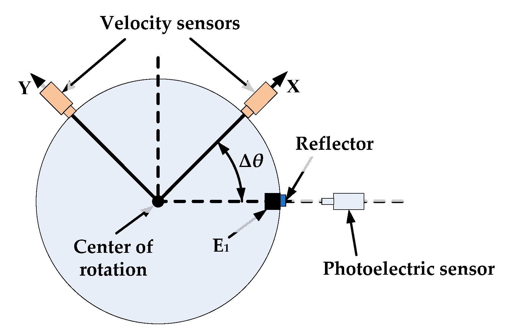
As the assembly angle of Rotor-1 is 0° by default, the position of the unbalanced mass point (E1) in Rotor-1 is used as the initial acquisition direction of the photoelectric sensor. As shown in Figure 5, the acquisition angle of the vibration response in X-direction is 45° (Δθ = 45°). The rotational speed of the four-stage rotor is set at 3000 rpm. The maximum value of the vibration velocities at the left and right bearings (at Node-6 and -38) of the four-stage rotor in steady-state is taken as the optimization objective to search the optimal assembly angles of the rotors at each stage.
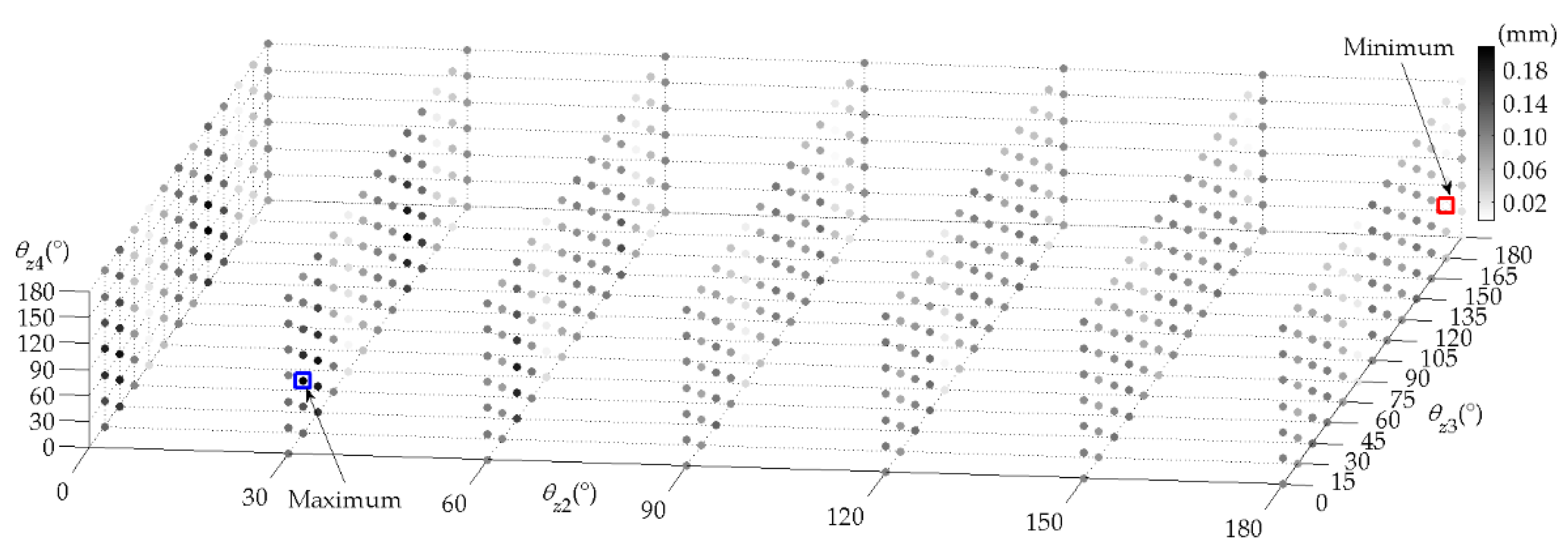
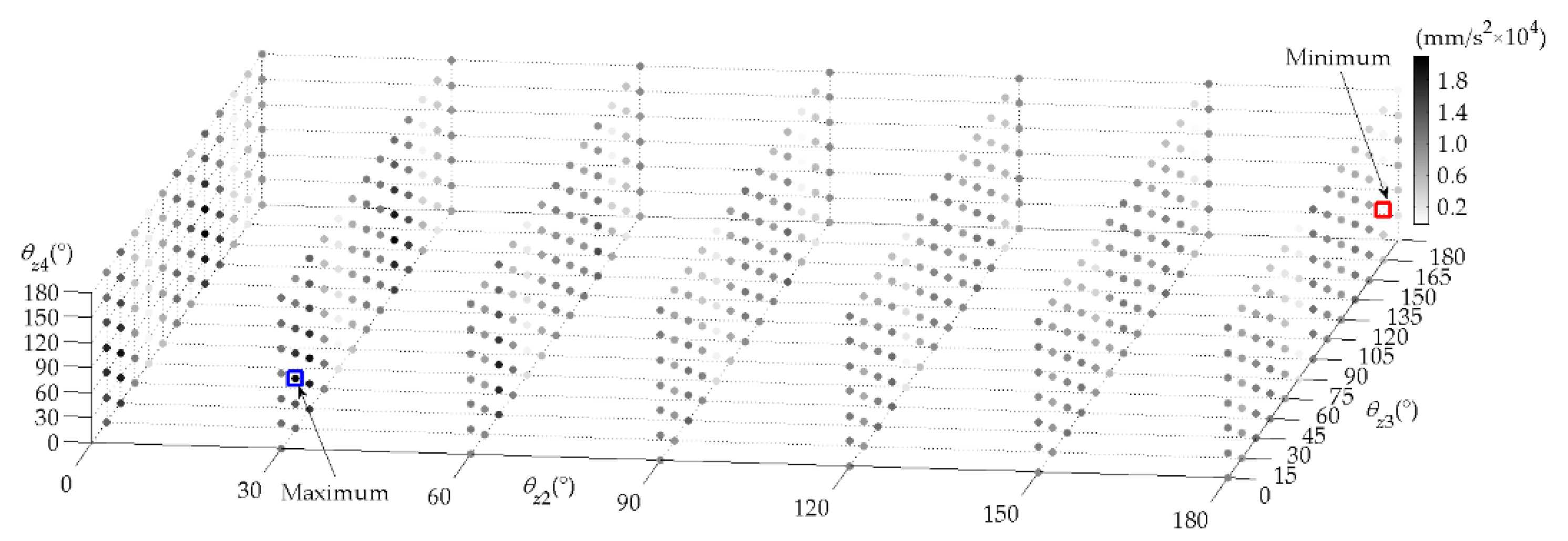
Figure 6, Figure 7 and Figure 8 show the maximum value of the vibration velocities, displacements and accelerations at the bearings under all possible sequences of the assembly angles (7 × 13 × 7 = 637), respectively. From Table 3, when the assembly angles of θz2, θz3 and θz4 are 180°, 165°, and 60°, the vibration velocities at Node-6 and -38 are 4.4630 and 3.5759 mm/s, respectively. Assembling according to the above assembly sequence can also minimize the vibration displacements and accelerations at Node-6 and -38. The maximum vibration response is at Node-6 under the optimal assembly, and the vibration velocity curves of Node-6 are shown in Figure 9.
In addition, when the assembly angles of θz2, θz3 and θz4 are 30°, 15°, and 60°, the vibration velocities at Node-6 and -38 are 40.5936 and 57.4941 mm/s, respectively. If the assembly is carried out according to the above assembly sequence, the vibration velocities at the bearings will reach the maximum. At the same time, the vibration displacement and acceleration can also reach the maximum (Table 4). The maximum vibration velocity is at Node-38 under the worst assembly, and the vibration velocity curves of Node-38 are shown in Figure 10.
When θz2, θz3 and θz4 are all 0°, the vibration velocity at Node-6 and -38 are 7.5441 and 10.8975 mm/s, respectively. From Table 5, the maximum vibration velocity, displacement and acceleration are all at Node-38 under the default assembly, and the vibration velocity curves of Node-38 are shown in Figure 11.
The maximum vibration velocity under the optimal assembly is reduced by 92.2% and 59.0% compared with that under the worst assembly and default assembly, respectively. The maximum vibration displacement under the optimal assembly is reduced by 89.0% and 59.1% compared with that under the worst assembly and default assembly, respectively. The maximum vibration velocity under the optimal assembly is reduced by 92.2% and 59.1% compared with that under the worst assembly and default assembly, respectively.

3.1.4. Effects of Stiffness and External Force on the Vibration Responses

The assembly angles under the optimal assembly, the worst assembly and the default assembly were obtained, respectively, in Section 3.1.3. This section will investigate the effects of the support stiffness and the external force changes on vibration response under the above three assembly states.
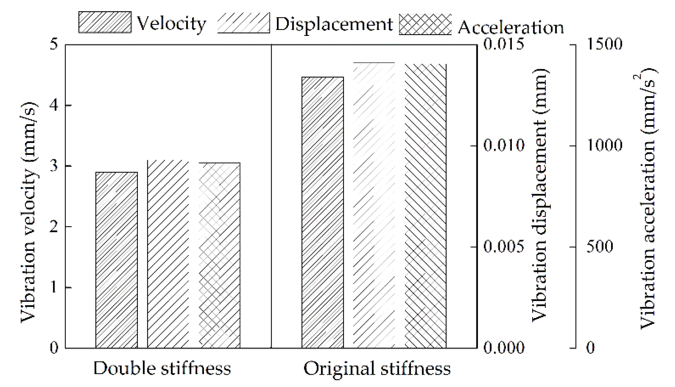
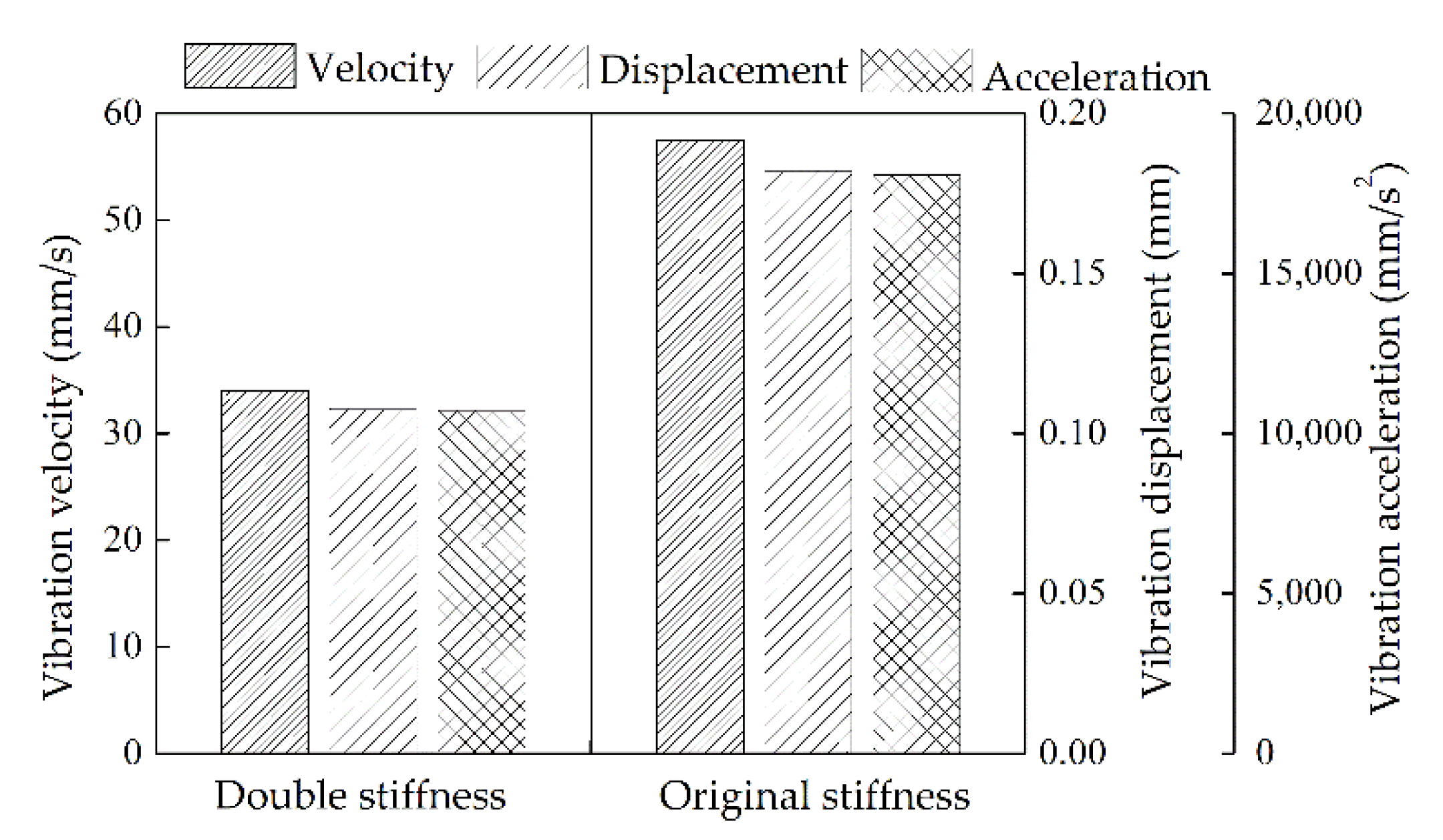
Firstly, the original stiffness coefficients were doubled, that is, Kxx = 1.6 × 10⁵ N/mm and Kyy = 2 × 10⁵ N/mm, and then the maximum vibration responses at the bearings (Node-6 and -38) under the new support stiffness were calculated. Table 6, Table 7 and Table 8 show the vibration responses at Node-6 and -38 under the optimal assembly, the worst assembly and the default assembly. Figure 12, Figure 13 and Figure 14 show that the increase of stiffness can reduce the maximum vibration responses at the bearings under the three assembly sequences above.
In addition, considering that the belt drive will be used in the experiments and there is a very light vertical downward preload on the measured rotor, an external force was added at the contact position between the belt and the rotor (Node-34), and the vibration responses under the optimal assembly were calculated when the external force is 5 N and 10 N, respectively. From Table 9, Table 10 and Table 11, because the external force was applied closer to the right bearing, the vibration response at Node-38 is significantly affected by the external force than that at Node-6.

3.2. Experimental Verification

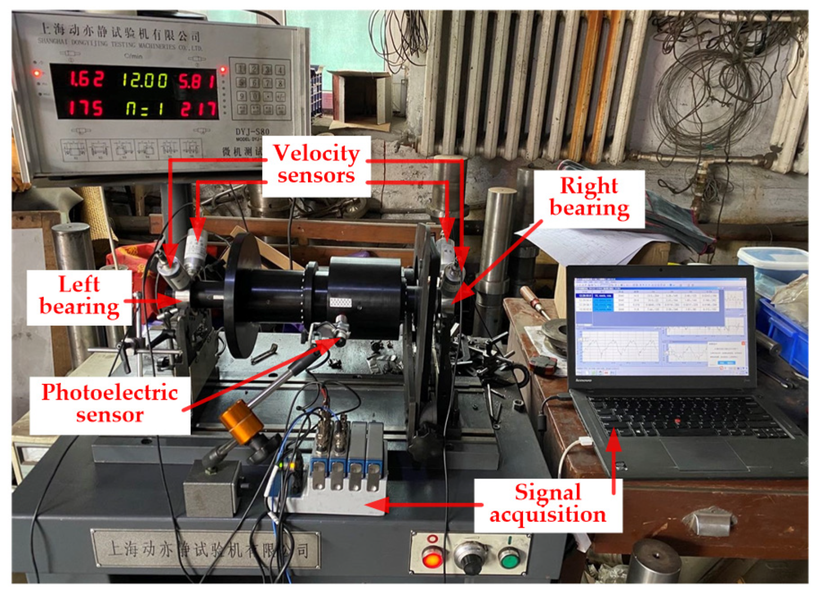
The experimental setup is shown in Figure 15. The measured rotor was placed on a dynamic balancing machine driven by a belt, and the original rollers support on both sides were refitted into two fixed bearings. The four single-stage rotors in Figure 4 were assembled according to the three assembly sequences (optimal, worst and default) obtained in Section 3.1.3, respectively. Then, the corresponding three vibration tests were carried out on the assembled four-stage rotor system at the rotational speed of 3000 rpm. The sensitivity of the velocity sensors in Figure 15 are all 20 mv/mm/m. The eight channel signal collector was manufactured by National Instruments Co., Ltd. (Austin, TX, USA).
The vibration velocity curves of the left bearing under the optimal assembly, worst assembly and default assembly are shown in Figure 16, Figure 17 and Figure 18, respectively, and that of the right bearing under the same assembly conditions are shown in Figure 19, Figure 20 and Figure 21. From Table 12, the maximum vibration velocities at the bearings in the four-stage rotor system under the optimal assembly, worst assembly and default assembly are 20.2505, 66.5348 and 37.1793 mm/s, respectively. The maximum vibration velocity under the optimal assembly is reduced by 69.6% and 45.5% compared with that under the worst assembly and default assembly, respectively. Although the reduction rate of the vibration velocities at the bearings after optimized assembly is lower than the simulation results, the optimization effect is still significant. The difference in support stiffness may cause the difference between the simulated and measured vibration velocities. It can be seen from the simulation results in Section 3.1.4 that the actual support stiffness in the experiments may be slightly lower than that in the simulations.
The experimental results verified the effectiveness of assembly optimization to a certain extent. However, unlike the simulation results, the maximum vibration velocities under the worst and default assembly appeared at the left bearing. This is because the belt applied a slight preload evenly distributed force to the rotor, which generates friction to drive the rotor to rotate, and this preload was closer to the right bearing, which may inhibit the vibration at the right bearing. Therefore, the vibration response at right bearing is significantly affected by the external force than that at left bearing.

4. Discussion

The aero-engine is composed of multistage rotors, and its primary function is to realize the pressurization of air step-by-step, thus providing an enormous power source. The vibration index of the multistage rotor system directly affects the safe operation and working efficiency of the aero-engine. However, the assembly process of the multistage rotor is complex. The traditional assembly process mainly depends on manual experiences matching the assembly angles, which often needs repeated disassembly to meet the vibration index. The existing assembly optimization methods only optimize the concentricity and unbalance of the multistage rotor, not directly optimize the vibration responses of the rotor. Therefore, to solve this problem, we established the direct relationship between the assembly angles of the rotors at each stage and the vibration responses of the rotor. The nodal vibration responses could be directly obtained by inputting the geometric and mass characteristic parameters of the rotor into the calculation model. In the simulation, we took the maximum vibration velocities at the left and right bearings of a scaled high-pressure rotor system as the optimization objective, and obtained the optimal assembly angles, making the maximum vibration velocities to the minimum. Although the optimization effect of the experiments was not as significant as that of the simulations, the vibration velocities at the bearings of the four-stage rotor could be significantly reduced by assembling according to the optimal assembly angles obtained by the simulation. As each test needs to be reassembled and clamped, the absolute consistency of the boundary conditions for each test cannot be fully guaranteed. Moreover, the support stiffness used in the simulation was also challenging to be entirely consistent with the actual support stiffness, which can only ensure that the boundary conditions of the three simulations and experiments are consistent. In the follow-up research, we plan to use a coupling drive instead of a belt-drive, which can eliminate the interference of the belt preload on the one hand, and investigate the suppression effect of the assembly optimization method proposed in this study on rotor vibration at higher rotational speed on the other hand.

5. Conclusions

In this study, we proposed a vibration suppression method for the multistage rotor of an aero-engine based on assembly optimization. The main contributions of this study can be summarized as follows:
  • The mathematical relationship between the assembly angles of the rotors at all stages and the nodal vibration responses was established by combining the error transfer model of the geometric and mass eccentricities with the dynamics model of the multistage rotor system.
  • An optimization function was developed, which takes the assembly angles as the optimization variables and the maximum vibration velocity at the bearings as the optimization objective. Then, the optimal assembly angles that can minimize the maximum vibration velocity at the bearings were calculated in the simulation.
  • The experimental results showed that the maximum vibration velocity at the bearings of the four-stage rotor system under the optimal assembly was reduced by 69.6% and 45.5% compared with that under the worst assembly and default assembly.

Author Contributions

Conceptualization, Y.C. and J.C.; methodology, Y.C.; software, Y.C.; validation, Y.C.; formal analysis, Y.C.; investigation, Y.C.; resources, J.C.; data curation, Y.C.; writing—original draft preparation, Y.C.; writing—review and editing, Y.C.; visualization, Y.C.; supervision, X.S.; project administration, J.C.; funding acquisition, J.C. All authors have read and agreed to the published version of the manuscript.

Funding

This research was funded by the Outstanding Youth Project of Natural Science Foundation of Heilongjiang Province, Grant JQ2019E002. The authors are grateful for the financial support.

Institutional Review Board Statement

Not applicable.

Informed Consent Statement

Not applicable.

Data Availability Statement

Not applicable.

Acknowledgments

The authors acknowledge Tan, JiuBin in Centre of Ultra-Precision Optoelectronic Instrument Engineering, Harbin Institute of Technology.

Conflicts of Interest

The authors declare no conflict of interest.

Appendix A

Table A1. The dimensional parameters of each element in the finite element model.
Elementln [mm]Dn [mm]dn [mm]
12200
216.5330
35330
43.5330
58350
65350
72390
82420
9264227
10244227
1135836
123580
138820
14151920
155820
163820
173.58254
18248272
19508272
203.510272
21311072
22711074
2319.58274
243.58256
25312856
261012848
2734128112
2846128112
29712848
30512850
31312833
326.56833
33304233
3420.54233
3511420
362390
375350
388350
393.5330
405330
4116.5330

References

  1. Chen, G. Vibration modelling and verifications for whole aero-engine. J. Sound Vib. 2015, 349, 163–176. [Google Scholar] [CrossRef]
  2. Cheng, W.; Guang, C. Wavelet correlation feature scale entropy and fuzzy support vector machine approach for aeroengine whole-body vibration fault diagnosis. Shock. Vib. 2013, 20, 341–349. [Google Scholar]
  3. Masrol, S.; Madlan, M.; Salleh, S. Vibration Analysis of Unbalanced and Misaligned Rotor System Using Laser Vibrometer. Appl. Mech. Mater. 2013, 315, 681–685. [Google Scholar] [CrossRef]
  4. Didier, J.; Sinou, J.; Faverjon, B. Study of the non-linear dynamic response of a rotor system with faults and uncertainties. J. Sound. Vib. 2012, 331, 671–703. [Google Scholar] [CrossRef] [Green Version]
  5. Ramlau, R.; Dicken, V.; Maa, P. Inverse imbalance reconstruction in rotordynamics. Zamm. J. Appl. Math. Mec. 2010, 86, 385–399. [Google Scholar] [CrossRef]
  6. Grobler, H.; Bright, G.; Loubser, R. Vibration analysis of a rotor by considering misalignment and unbalance, 18th ICSV. Sound Vibr. 2011, 3, 2151–2158. [Google Scholar]
  7. Juan, C.; Sanchez, L.; Hernandez, I. Classification of unbalance and misalignment in induction motors using orbital analysis and associative memories. Neurocomputing 2016, 175, 838–850. [Google Scholar]
  8. Hussain, T.; Yang, Z.; Popov, A.A. Straight-build assembly optimization: A method to minimize stage-by-stage eccentricity error in the assembly of axisymmetric rigid components (two-dimensional case study). J. Manuf. Sci. Eng. 2011, 133, 031014. [Google Scholar] [CrossRef]
  9. Hussain, T.; Mcwilliam, S.; Popov, A.A. Geometric error reduction in the assembly of axis-symmetric rigid components: A two-dimensional case study. Proc. Inst. Mech. Eng. Part B J. Eng. Manuf. 2012, 226, 1259–1274. [Google Scholar] [CrossRef]
  10. Hussain, T.; Yasinshaikh, G.; Shaikh, S.A. Variation propagation control in straight-build assemblies: 2d case study. Mehran Univ. Res. J. Eng. Technol. 2013, 32, 71–80. [Google Scholar]
  11. Zhang, Y.; Hussian, T.; Popov, A.A. Novel optimization technique for variation propagation control in an aero-engine assembly. Proc. Inst. Mech. Eng. Part B J. Eng. Manuf. 2010, 225, 100–111. [Google Scholar]
  12. Zhang, Y.; Popov, A.A.; Mcwilliam, S. Variation propagation control in mechanical assembly of cylindrical components. J. Manuf. Syst. 2012, 31, 162–176. [Google Scholar]
  13. Zhang, Y.; Hussian, T.; Popov, A.A. A comparison of different optimization techniques for variation propagation control in mechanical assembly. IOP Conf. 2011, 26, 012017. [Google Scholar]
  14. Zhang, Y.; Popov, A.A.; Mcwilliam, S.; Hussian, T. Dimensional variation propagation analysis in straight-build mechanical assemblies using a probabilistic approach. J. Manuf. Syst. 2013, 32, 348–356. [Google Scholar]
  15. Sun, J.; Ding, S.; Li, Z. Point-based solution using Jacobian-Torsor theory into partial parallel chains for revolving components assembly. J. Manuf. Syst. 2017, 46, 46–58. [Google Scholar]
  16. Sun, Y.; Guo, J.; Hong, J. Repair decision based on sensitivity analysis for aero-engine assembly. Int. J Precis. Eng. Man. 2019, 20, 347–362. [Google Scholar] [CrossRef]
  17. Wang, L.; Sun, C.; Tan, J. Improvement of location and orientation tolerances propagation control in cylindrical components assembly using stack-build assembly technique. Assem. Autom. 2015, 34, 358–366. [Google Scholar] [CrossRef]
  18. Sun, C.; Li, C.; Liu, Y. Prediction method of concentricity and perpendicularity of aero engine multistage rotors based on PSO-BP neural network. IEEE Access 2019, 7, 132271–132278. [Google Scholar] [CrossRef]
  19. Ganine, V.; Laxalde, D.; Michalska, H.; Pierre, C. Parameterized reduced order modeling of misaligned stacked disks rotor assemblies. J. Sound Vib. 2011, 330, 445–460. [Google Scholar] [CrossRef] [Green Version]
  20. Liu, Y.; Zhang, M.; Sun, C. A method to minimize stage-by-stage initial unbalance in the aero engine assembly of multistage rotors. Aerosp. Sci. Technol. 2018, 85, 270–276. [Google Scholar] [CrossRef]
  21. Piskin, A.; Aktas, H.E.; Topal, A. Rotor balancing with turbine blade assembly using ant colony optimization for aero-engine applications. Int. J. Turbo Jet-Engines 2017, 8, 60. [Google Scholar] [CrossRef]
  22. Chen, Y.; Cui, J.; Sun, X. An unbalance optimization method for a multi-Stage rotor based on an assembly error propagation model. Appl. Sci. 2021, 11, 887. [Google Scholar] [CrossRef]
  23. Sun, C.; Liu, Z.; Liu, Y. An adjustment method of geometry and mass centers for precision rotors assembly. IEEE Access 2019, 7, 169992–170002. [Google Scholar] [CrossRef]
  24. Chen, Y.; Cui, J.; Sun, X. Research on multistage rotor assembly optimization methods for aeroengine based on the genetic algorithm. Complexity 2021, 2021, 8847690. [Google Scholar] [CrossRef]
  25. Chen, Y.; Cui, J.; Sun, X. An assembly method for the multistage rotor of an aero-engine based on the dual objective synchronous optimization for the coaxality and unbalance. Aerospace 2021, 8, 94. [Google Scholar] [CrossRef]
  26. Genta, G. Dynamics of Rotating Systems; Springer: New York, NY, USA, 2005; pp. 160–184. [Google Scholar]
  27. Guang, Z.; Yi, S.; Zhan, L. Application of a forecasting coupling method to the non-linear dynamic analysis of a flexible rotor supported by externally pressurized orifices hybrid gas bearings. Proc. Inst. Mech. Eng. Part J J. Eng. Tribol. 2011, 225, 704–717. [Google Scholar] [CrossRef]
  28. Tang, Y. Advanced Structural Dynamics; Tianjin University Press: Tianjin, China, 2002; pp. 115–119. [Google Scholar]
Figure 1. Single-node dynamics model for a rotor with geometric and mass eccentricities.
Machines 09 00189 g001
Figure 2. Coordinate transfer process of a three-stage simulated rotor.
Machines 09 00189 g002
Figure 3. The finite element model of the simulated 4-stage high-pressure rotor system.
Machines 09 00189 g003
Figure 4. The measurement of the geometric parameters of each single-stage rotor.
Machines 09 00189 g004
Figure 5. The sensor settings of the 4-stage rotor.
Machines 09 00189 g005
Figure 6. The maximum value of the vibration velocities at the bearings under all possible sequences of the assembly angles.
Machines 09 00189 g006
Figure 7. The maximum value of the vibration displacements at the bearings under all possible sequences of the assembly angles.
Machines 09 00189 g007
Figure 8. The maximum value of the vibration accelerations at the bearings under all possible sequences of the assembly angles.
Machines 09 00189 g008
Figure 9. The vibration velocity curves of Node-6 under the optimal assembly. (a) X−direction; (b) Y−direction; (c) resultant velocity.
Machines 09 00189 g009
Figure 10. The vibration velocity curves of Node-6 under the worst assembly. (a) X−direction; (b) Y−direction; (c) resultant velocity.
Machines 09 00189 g010
Figure 11. The vibration velocity curves of Node-6 under the default assembly. (a) X−direction; (b) Y−direction; (c) resultant velocity.
Machines 09 00189 g011
Figure 12. The maximum value of the vibration accelerations at the bearings under all possible sequences of the assembly angles.
Machines 09 00189 g012
Figure 13. The maximum value of the vibration accelerations at the bearings under all possible sequences of the assembly angles.
Machines 09 00189 g013
Figure 14. The maximum value of the vibration accelerations at the bearings under all possible sequences of the assembly angles.
Machines 09 00189 g014
Figure 15. Experimental setup.
Machines 09 00189 g015
Figure 16. The vibration velocity curves of the left bearing under the optimal assembly. (a) X−direction; (b) Y−direction; (c) resultant velocity.
Machines 09 00189 g016
Figure 17. The vibration velocity curves of the left bearing under the worst assembly. (a) X−direction; (b) Y−direction; (c) resultant velocity.
Machines 09 00189 g017
Figure 18. The vibration velocity curves of the left bearing under the default assembly. (a) X−direction; (b) Y−direction; (c) resultant velocity.
Machines 09 00189 g018
Figure 19. The vibration velocity curves of the right bearing under the optimal assembly. (a) X−direction; (b) Y−direction; (c) resultant velocity.
Machines 09 00189 g019
Figure 20. The vibration velocity curves of the right bearing under the worst assembly. (a) X−direction; (b) Y−direction; (c) resultant velocity.
Machines 09 00189 g020
Figure 21. The vibration velocity curves of the right bearing under the default assembly. (a) X−direction; (b) Y−direction; (c) resultant velocity.
Machines 09 00189 g021
Table 1. The unbalanced masses of the rotors at all stages and their coordinates produced by the M5 through-holes.
Unbalanced Mass Pointsun [g]Coordinates of En [mm]
E10.296(17.25, 0, 35)
E20.197(38.5, 0, 58.5)
E30.314(60, 0, 77)
E40.178(18.75, 0, 36.5)
Table 2. The measured geometric parameters of the 4-stage rotor.
Componentsξn [mm]h1 [mm]w1 [mm]δn [°]
Rotor-1(0.0181, 0.0062, 65.0152)0.019336.0220113
Rotor-2(−0.009, −0.0223, 115.0210)0.0235101.989529
Rotor-3(0.0056, 0.0244, 138.1047)0.024150.0149242
Rotor-4(0.0116, 0.0124, 74.9581)--182
Table 3. The vibration responses at Node-6 and -38 under the optimal assembly (θz2 = 180°, θz3 = 165°, θz4 = 60°).
PositionVibration Velocity
[mm/s]
Vibration Displacement
[mm]
Vibration Acceleration
[mm/s2]
Node-64.46300.01411.4044 × 103
Node-383.57590.01131.1259 × 103
Table 4. The vibration responses at Node-6 and -38 under the worst assembly (θz2 = 30°, θz3 = 15°, θz4 = 60°).
PositionVibration Velocity
[mm/s]
Vibration Displacement
[mm]
Vibration Acceleration
[mm/s2]
Node-640.59360.12851.2785 × 104
Node-3857.49410.18201.8076 × 104
Table 5. The vibration responses at Node-6 and -38 under the default assembly (θz2 = 0°, θz3 = 0°, θz4 = 0°).
PositionVibration Velocity
[mm/s]
Vibration Displacement
[mm]
Vibration Acceleration
[mm/s2]
Node-67.54410.02392.3778 × 103
Node-3810.89750.03453.4298 × 103
Table 6. The vibration responses at Node-6 and -38 under the optimal assembly.
PositionVibration Velocity
[mm/s]
Vibration Displacement
[mm]
Vibration Acceleration
[mm/s2]
Node-62.90010.00930.9149 × 103
Node-382.11210.00740.8221 × 103
Table 7. The vibration responses at Node-6 and -38 under the worst assembly.
PositionVibration Velocity
[mm/s]
Vibration Displacement
[mm]
Vibration Acceleration
[mm/s2]
Node-625.11360.07957.9071 × 103
Node-3834.02710.10771.0713 × 104
Table 8. The vibration responses at Node-6 and -38 under the default assembly.
PositionVibration Velocity
[mm/s]
Vibration Displacement
[mm]
Vibration Acceleration
[mm/s2]
Node-64.47760.01761.7205 × 103
Node-387.93120.02842.4682 × 103
Table 9. The vibration velocities at Node-6 and -38 under different external forces.
External Force
[N]
Vibration Velocity at Node-6
[mm/s]
Vibration Velocity at Node-38
[mm/s]
04.46303.5759
54.31093.1741
104.10342.4683
Table 10. The vibration displacements at Node-6 and -38 under different external forces.
External Force
[N]
Vibration Displacement at Node-6
[mm]
Vibration Displacement at Node-38
[mm]
00.01410.0113
50.01280.0088
100.01170.0064
Table 11. The vibration accelerations at Node-6 and -38 under different external forces.
External Force
[N]
Vibration Acceleration at Node-6
[mm/s2]
Vibration Acceleration at Node-38
[mm/s2]
00.9149 × 1030.8221 × 103
50.8058 × 1030.6072 × 103
100.7129 × 1030.4305 × 103
Table 12. The vibration velocities at the left and right bearings.
StateMaximum of fl(γ)
[mm/s]
Maximum of fr(γ)
[mm/s]
Optimal assembly20.250517.1042
Worst assembly66.534855.5799
Default assembly37.179332.4968
Publisher’s Note: MDPI stays neutral with regard to jurisdictional claims in published maps and institutional affiliations.