Article

RISE-Based Composite Adaptive Control of Electro-Hydrostatic Actuator with Asymptotic Stability

School of Mechanical Engineering, Nanjing University of Science and Technology, Nanjing 210094, China
*
Author to whom correspondence should be addressed.
Machines 2021, 9(9), 181; https://doi.org/10.3390/machines9090181
Submission received: 21 July 2021 / Revised: 19 August 2021 / Accepted: 24 August 2021 / Published: 26 August 2021
(This article belongs to the Special Issue Advanced Control of Industrial Electro-Hydraulic Systems)

Abstract

:
The electro-hydrostatic actuator (EHA), the actuator of electric drive and hydraulic transmission, is competitive since it is small in size, light in weight and high in power density. However, the existence of the velocity loop error of servo motors, unmodeled dynamics and highly nonlinear uncertainties restrict the improvement of the tracking accuracy of the EHA system. In order to achieve high-precision motion control of EHAs, a RISE-based composite adaptive control scheme is proposed in this paper. In the proposed composite adaptive control design, a novel parameter adaptive law is synthesized to compensate for the parametric uncertainties and a robust integral of the sign of error (RISE) feedback is utilized to suppress the adverse effects caused by the lumped disturbances, including the velocity loop error of a servo motor and other unmodeled dynamics. The synthesized parameter adaptive law possesses the advantage of fast convergence, which is beneficial to achieve transient tracking performance improvement. In addition, the proposed controller is more suitable for practical applications since it is chattering free. The closed-loop system stability analysis shows that the proposed control scheme guarantees an excellent asymptotic tracking performance. Finally, comparative simulations are conducted to verify the high-performance nature of the proposed controller.

1. Introduction

The hydraulic actuator servo control system is one of the key factors for flight control systems to realize the flight attitude of aircraft. Its performance affects the overall performance of aircraft, such as maneuverability, reliability, survivability, etc. [1,2,3,4,5]. In the airborne actuation system of aircraft, the traditional hydraulic system will gradually be replaced by the power-by-wire (PBW) flight control system due to easy leakage, low efficiency and complex pipelines. The PBW achieves the power transmission between the aircraft’s secondary energy system and the various actuators in the form of electric energy through cables, eliminating the need for a central hydraulic system and hydraulic pipelines all over the fuselage. It greatly improves the reliability, efficiency and survivability of the aircraft and contributes to the realization of multi-electric/all-electric aircraft. The electro-hydrostatic actuator (EHA), as a typical power fly-by-wire actuator, was developed first [6,7,8,9]. Subsequently, in the field of vibration damping and industrial actuators, the application of EHAs was also realized [10,11].
The EHA is an integrated actuator of the power fly-by-wire system. A closed-circuit system is adopted, which has no main control valve group. In consequence, the EHA has high system efficiency and a large power to weight ratio [12,13] compared to the valve control system. The electric energy is directly converted into hydraulic energy at the actuator end, and then the hydraulic energy is converted into mechanical energy of the cylinder, which has the advantages of both hydraulic drive and electric drive actuators. The modular design is very simple for EHA systems, because there is no centralized oil source and it only includes an electrical interface and mechanical structure externally [14]. Despite all of the advantages of the EHA, the evolution of its location tracking performance remains a significant challenge. Nonlinear uncertainties and high-order unmodeled dynamics caused by friction, flow leakage and disturbances make the precision motion control difficult [15]. In addition, the velocity loop control of servo motors causes errors in the input speed of pumps, which also affects the control performance of EHA systems. Therefore, it is urgent to design advanced control algorithms to solve the above problems.
For the control strategy research of a pump control system that has been reported, Zheng et al. [16] used a self-tuning fuzzy PID control algorithm on a volume control hydraulic system driven by SRM directly and the PID controller parameters can be self-tuned online by the error and change in error by using fuzzy logic. In [17], a model predictive control algorithm was applied to the servo motor-driven constant pump hydraulic system in an injection molding process, but the feasibility of the algorithm was only verified by simulation. In order to solve the efficiency problem of a servo motor pump, a sliding-mode controller was designed in [18], which improved the energy efficiency and the motion tracking performance simultaneously. A robust discrete-time sliding-mode controller [19] was designed, which considered the nonlinearities of a fluid power EHA system, especially the nonlinear friction. In [11,20], a PID precise control algorithm based on the pump direct-drive technology was used in a manipulator with hydraulic hybrid servo boosters. In [21], an adaptive backstepping controller of an electro-hydraulic actuator was presented, in which high steady-state accuracy was achieved. In [22], aiming at the pump-controlled hydraulic servo system, an adaptive fuzzy controller with self-tuning fuzzy sliding-mode compensation was designed to control the pitch angle. To sum up, the nonlinear dynamics and parameter uncertainty of the EHA system are not fully considered by the above control methods, and input error caused by servo motor speed loop control is not reflected in the modeling process. At the same time, how to ensure asymptotic tracking is still not well addressed.
To this end, lots of advanced nonlinear control strategies have been studied. As an excellent control method in high-precision control of nonlinear systems, the robust integral of the sign of the error (RISE) control approach has been deeply studied by many scholars. An appealing feature of the RISE control is that it can obtain asymptotic tracking performance as long as the matched unmodeled disturbance has enough time derivatives to ensure that the disturbance is sufficiently smooth and bounded. Some high-accuracy controllers based on the RISE method for hydraulic systems were designed in [23,24,25,26]. In [23], a continuous RISE-based control was first proposed. The greatest contribution of this control algorithm is that the asymptotic stability of the system is achieved without the application of switching functions similar to those in sliding-model control. In [24], the internal leakage model was established, and the asymptotic tracking control of the hydraulic system was realized by the method of parameter adaptation and RISE. In [25], a RISE-based controller with parameter adaptation was developed for a cascade hydraulic system. In [26], an adaptive integral control strategy with adjustable integral robust gains was proposed, which effectively avoided the randomness and potential high gain feedback problems of the traditional RISE controller. In addition, RISE-based control was also successfully applied to various physical nonlinear systems [27,28,29,30]. To sum up, the RISE-based adaptive controller not only can achieve high tracking performance through high feedback gains, but also ensure asymptotically stable tracking. It is still available for practical applications despite being limited by measurement noise, high-frequency dynamics and sampling frequency. In addition, the steady-state tracking performance of the RISE-based controller is much improved compared with the linear robust controller.
Based on the above analysis, this paper cleverly combines the composite parameter adaptive method [31] based on parameter estimation errors with the RISE method, and proposes a RISE-based composite adaptive control of EHA systems. The key to the controller design is how to integrate the RISE-based controller with the composite parameter adaptive method to reduce the system tracking error and achieve high-precision motion control. Firstly, a composite adaptive law based on parameter estimation errors is proposed to deal with the parameter uncertainties in EHA systems. The adaptive rate can not only guarantee the tracking performance of the system, but also improve the convergence speed of the adaptive rate. A RISE-based controller is then used to suppress the lumped disturbances, including input errors in the servo motor speed loop control, unmodeled dynamics and highly nonlinear uncertainties. The contributions of this paper include the following aspects: (1) A new composite adaptive controller which combines the composite adaptive law and RISE feedback is proposed to deal with parametric uncertainties and unmodeled disturbances, respectively; (2) the synthesized parameter adaptive law can achieve faster convergence of parameter estimation than the traditional adaptive law, which is beneficial to the transient tracking performance improvement; (3) compared with most existing methods which can only obtain bounded tracking errors, the proposed control scheme theoretically guarantees an excellent asymptotic stability result, which is vital for high-performance control of EHAs.
This paper is arranged as follows: Dynamics modeling of the hydraulic system is presented in Section 2. Section 3 gives the RISE-based composite adaptive controller design procedure and its theoretical results. Simulation results are shown in Section 4. Conclusions can be found in Section 5.

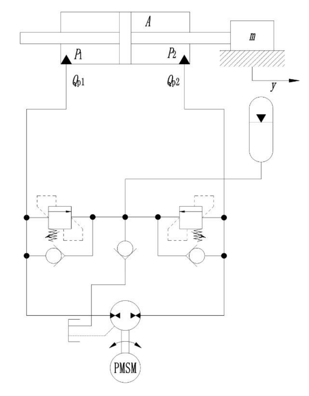
2. Dynamics Modeling

The EHA in this paper adopts the scheme of fixed pump displacement and variable motor speed (FPVM), and its schematic diagram is shown in Figure 1. The permanent magnet synchronous motor (PMSM) drives the axial piston pump, which provides the system flow and pressure to push the hydraulic cylinder to move with a load. The main function of the accumulator is to reduce the pressure pulsation of the system and ensure the lowest oil suction pressure of the piston pump.
According to the Newton’s law, the dynamic equation of the EHA can be written as
m y ¨ = F B y ˙ d 1 ( t )
where m and y are the load mass and displacement, respectively, F = A(P1P2) is the force applied to the load by a hydraulic cylinder, P1 and P2 are the pressure values inside the two chambers of the actuator, respectively, A is the effective piston area of the hydraulic cylinder chamber, respectively, B is the viscous friction coefficient, d1(t) is the modeling disturbance including the unmodeled part of friction and external disturbances, etc.
Taking the derivative of (1), we have
m y = A ( P ˙ 1 P ˙ 2 ) B y ¨ d ˙ 1 ( t )
Considering the oil compressibility, the pressure dynamics of the hydraulic actuator can be expressed as
V 1 β e P ˙ 1 = Q 1 A y ˙ C t 1 ( P 1 P 2 ) + q 1 ( t ) V 2 β e P ˙ 2 = Q 2 + A y ˙ + C t 1 ( P 1 P 2 ) q 2 ( t )
in which V1 = V01 + Ay and V2 = V02Ay denote the control volume inside the two chambers of the actuator, respectively; V01 and V02 denote the original total volumes of the two chambers; β e denotes the effective oil bulk modulus; Ct1 denotes the internal leakage coefficient of the actuator; Q1 denotes the supplied flow rate of the forward chamber, and Q2 denotes the return flow rate of the return chamber; q1(t) and q2(t) denote the unmodeled dynamics and disturbances.
For an EHA system, the flow rate out of the pump is numerically equal to the flow rate in, without accounting for external leakage. Considering the velocity loop control of servo motors, the actual input speed of the pump is w = ku + zm, wherein the motor input speed is obtained by multiplying the voltage signal u and the amplification factor k. zm is the velocity loop error of the servo motor.
Thus, the load flow Q1 can be modeled as
Q 1 = Q 2 = D w C t 2 ( P 1 P 2 )
in which D denotes the displacement of the piston pump; Ct2 denotes the internal leakage coefficient of the actuator.
From (2)–(4), we have
A ( P ˙ 1 P ˙ 2 ) = A β e V 1 [ Q 1 A y ˙ C t 1 ( P 1 P 2 ) + q 1 ( t ) ] A β e V 2 [ Q 2 + A y ˙ + C t 1 ( P 1 P 2 ) q 2 ( t ) ] = A β e ( 1 V 1 + 1 V 2 ) D k u A 2 β e ( 1 V 1 + 1 V 2 ) y ˙ A β e ( 1 V 1 + 1 V 2 ) ( C t 1 + C t 2 ) ( P 1 P 2 ) + A β e V 1 q 1 ( t ) + A β e V 2 q 2 ( t )
Defining the state variables x = [ x 1 , x 2 , x 3 ] T = [ y , y ˙ , y ¨ ] T , the state-space form of the hydraulic system through (1), (2) and (5) can be written as
x ˙ 1 = x 2 x ˙ 2 = x 3 x ˙ 3 = f 1 m θ 1 u f 1 m θ 2 x 2 ( B m + f 1 θ 3 ) x 3 + Δ
where
f 1 = A ( 1 V 1 + 1 V 2 ) θ 1 = β e D k m θ 2 = ( A + ( C t 1 + C t 2 ) B A ) β e θ 3 = β e ( C t 1 + C t 2 ) A Δ = f 1 m β e D z m + d ˙ 1 ( t ) m + f 1 A m ( C t 1 + C t 2 ) β e d 1 ( t ) + A β e m v 1 q 1 ( t ) + A β e m v 2 q 2 ( t )
in which Δ represents lumped disturbances.
Our goal is to track the reference trajectory xd as closely as possible. Before designing the controller, some assumptions are given as follows:
Assumption 1.
The disturbance Δ in (6) is smooth and satisfies
Δ ˙ σ 1 , | Δ ¨ | σ 2
where σ 1 and σ 2 are unknown non-negative constants.
Assumption 2.
The desired position trajectory x d 3 and is bounded in actual hydraulic systems under normal working conditions.
Assumption 3.
The set of parameters θ when defined satisfies:
θ Ω θ θ : θ min θ θ max
where θ max = [ θ 1 max ; θ 2 max ; θ 3 max ] , θ min = [ θ 1 min ; θ 2 min ; θ 3 min ] are known upper and lower bounds.

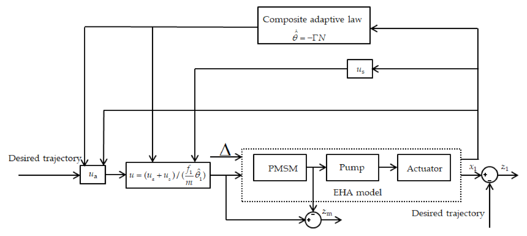
3. RISE-Based Composite Adaptive Controller Design

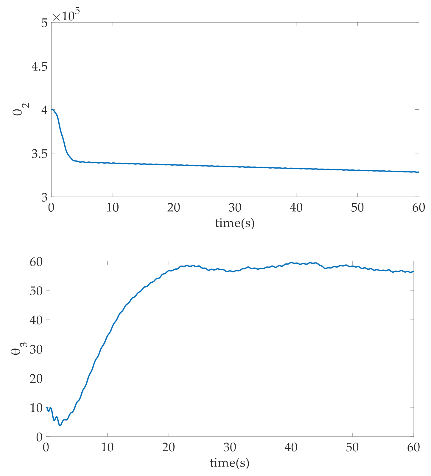
3.1. Composite Parameter Adaptation

In order to complete the parameter adaptation design, we rewrite the system (6) into the following form
x ˙ 1 = x 2 x ˙ 2 = x 3 x ˙ 3 = φ T θ + g ( x ) + Δ
where φ = [ f 1 m u ; f 1 m x 2 ; f 1 x 3 ] ; θ = [ θ 1 ; θ 2 ; θ 3 ] = [ β e D k m ; ( A + ( C t 1 + C t 2 ) B A ) β e ; β e ( C t 1 + C t 2 ) A ] ; g ( x ) = B m x 3 .
First-order filtering is performed on both sides of Equation (10) to obtain the following relation:
k x ˙ 3 f + x 3 f = x 3 , x 3 f ( 0 ) = 0 k g ˙ ( x ) f + g ( x ) f = g ( x ) , g f ( 0 ) = 0 k Δ ˙ f + Δ f = Δ , Δ f ( 0 ) = 0 k φ ˙ f + φ f = φ , φ f ( 0 ) = 0
in which ( · ) f represents the filtering output of · ; k is positive.
Thus, we have
R f = x ˙ 3 f g ( x ) f Δ f = φ f T θ
The following variables are defined:
H ˙ = j H + φ f φ f T , H ( 0 ) = 0 I ˙ = j I + φ f R f , I ( 0 ) = 0
where j is positive.
Therefore, the solution of (13) is
H ( t ) = 0 t e j ( t v ) φ f ( v ) φ f T ( v ) d v I ( t ) = 0 t e j ( t v ) φ f ( v ) R f ( v ) d v
From (14), we can obtain
I = H θ
Obviously, we can figure out the unknown θ from known H and I, and we define
N = H θ ^ I = H θ ˜
in which θ ^ is the estimation of θ and θ ˜ = θ ^ - θ is the estimation error of θ .
Therefore, the composite parameter adaptive law can be constructed by
θ ^ ˙ = Γ N
where Γ is a positive diagonal matrix.

3.2. Controller Design

For ease of designing the controller, the following variables are defined
z 1 = x 1 x 1 d z 2 = k 1 z 1 + z ˙ 1 z 3 = k 2 z 2 + z ˙ 2 r = k 3 z 3 + z ˙ 3
in which k 1 , k 2 and k 3 are positive constants.
Based on (6) and (18), we can obtain
r = k 3 z 3 + k 2 z ˙ 2 + z ¨ 2 = k 3 z 3 + k 2 z ˙ 2 + ( k 1 z ¨ 1 + z 1 ) = k 3 z 3 + k 2 z ˙ 2 + k 1 ( z ˙ 2 k 1 z ˙ 1 ) + x ˙ 3 x 1 d = x ˙ 3 x 1 d + ( k 1 + k 2 + k 3 ) z 3 ( k 1 2 + k 2 2 + k 1 k 2 ) z 2 + k 1 3 z 1 = f 1 m θ 1 u f 1 m θ 2 x 2 ( B m + f 1 θ 3 ) x 3 + Δ x 1 d + ( k 1 + k 2 + k 3 ) z 3 ( k 1 2 + k 2 2 + k 1 k 2 ) z 2 + k 1 3 z 1
Based on (19), the control law of the system can be designed as follows:
u = ( u a + u s ) / ( f 1 m θ ^ 1 ) u a = f 1 m θ ^ 2 x 2 + ( B m + f 1 θ ^ 3 ) x 3 + x 1 d ( k 1 + k 2 + k 3 ) z 3 + ( k 1 2 + k 2 2 + k 1 k 2 ) z 2 k 1 3 z 1 u s = k r z 3 k r k 3 z 3 + β s i g n ( z 3 ) d t
where s i g n ( · ) is the signum function; k r and β are positive constants.
In (20), ua is the model-based adaptive feedforward compensation term which is designed to achieve accurate model compensation and then improve the tracking performance, us is the nonlinear robust control law which is constructed to attenuate the effects of unmodeled disturbances on the control performance.
Substituting (20) into (19), we obtain
r = f 1 m θ ˜ 1 u + f 1 m θ ˜ 2 x 2 + f 1 θ ˜ 3 x 3 + Δ k r z 3 k r k 3 z 3 + β s i g n ( z 3 ) d t
Therefore, the derivative of r is
r ˙ = k r r β s i g n ( z 3 ) + ρ
in which ρ = φ ˙ T θ φ T θ ˜ ˙ + Δ ˙ . It is worth noting that ρ σ 1 , ρ ˙ σ 2 in practice, where σ 1 and σ 2 are positive constants.
The flow diagram of RISE-based composite adaptive controller is shown in Figure 2 below.

3.3. Closed-Loop Stability Analysis

To promote the later stability analysis, a lemma is given as follows:
Lemma 1.
There is always a non-negative constant β satisfying β > σ 1 + σ 2 / k 3 such that the following function Ε ( t ) is positive
E ( t ) = β z 3 ( 0 ) + z 3 ( 0 ) ρ ( 0 ) 0 t M ( τ ) d τ
in which M ( t ) is defined as M ( t ) = r [ ρ β s i g n ( z 3 ) ] .
Proof of Lemma 1.
Substituting (18) into (23) and integrating in time, there is
0 t M ( τ ) d τ = 0 t [ z ˙ 3 + k 3 z 3 ] [ ρ ( τ ) + β s i g n ( z 3 ( τ ) ) ] d τ = 0 t [ ρ + β s i g n ( z 3 ) ] d z 3 0 t k 3 z 3 [ ρ + β s i g n ( z 3 ) ] d τ
Next, we yield
0 t M ( τ ) d τ = [ ρ z 3 β z 3 ] 0 t + 0 t z 3 d ρ + 0 t [ k 3 z 3 ρ k 3 β z 3 ] d τ = [ ρ ( t ) z 3 ( t ) β z 3 ( t ) ] + [ ρ ( 0 ) z 3 ( 0 ) + β z 3 ( 0 ) ] + 0 t z 3 d ρ d τ d τ + 0 t [ k 3 z 3 ρ k 3 β z 3 ] d τ
Given the upper bound of the right-hand side of (25), the following inequality is obtained.
0 t M ( τ ) d τ z 3 [ σ 1 β ] + [ ρ ( 0 ) z 3 ( 0 ) + β z 3 ( 0 ) ] + 0 t z 3 σ 2 d τ + 0 t z 3 [ k 3 σ 1 k 3 β ] d τ = z 3 [ σ 1 β ] + [ ρ ( 0 ) z 3 ( 0 ) + β z 3 ( 0 ) ] + 0 t z 3 σ 2 d τ + 0 t z 3 [ k 3 σ 1 + σ 2 k 3 β ] d τ
From (26), (23) holds if β > σ 1 + σ 2 / k 3 is satisfied, which proves Lemma 1. □
Theorem 1.
Based on the composite parameter adaptive law (17) and the control law (20), by choosing the right parameters k 1 , k 2 , k 3 , k r , Γ , k , l and β , it ensures that all system signals are bounded in the closed-loop system, and asymptotic output tracking can be obtained, i.e., z1→0 as t∞.
Proof of Theorem 1.
The following Lyapunov function is defined:
V = 1 2 z 1 2 + 1 2 z 2 2 + 1 2 z 3 2 + 1 2 r 2 + 1 2 θ ˜ T θ ˜ + E
Then, the derivative of V can be written as
V ˙ = z 1 z ˙ 1 + z 2 z ˙ 2 + z 3 z ˙ 3 + r r ˙ + θ ˜ T θ ^ ˙ + E ˙ = z 1 ( z 2 k 1 z 1 ) + z 2 ( z 3 k 2 z 2 ) + z 3 ( r k 3 z 3 ) + r ( k r r β s i g n ( z 3 ) ρ ) θ ˜ T Γ N M = k 1 z 1 2 + z 1 z 2 k 2 z 2 2 + z 2 z 3 k 3 z 3 2 + z 3 r k r r 2 + r ( β s i g n ( z 3 ) ρ ) θ ˜ Γ H θ ˜ r ( β s i g n ( z 3 ) ρ ) = k 1 z 1 2 + z 1 z 2 k 2 z 2 2 + z 2 z 3 k 3 z 3 2 + z 3 r k r r 2 θ ˜ T Γ H θ ˜
According to the Young’s inequality, when p = q = 2 , we have
V ˙ ( k 1 1 2 ) z 1 2 ( k 2 1 ) z 2 2 ( k 3 1 ) z 3 2 ( k r 1 2 ) r 2 λ min ( Γ H ) θ ˜ T θ ˜ γ ( z 1 2 + z 2 2 + z 3 2 + r 2 + θ ˜ T θ ˜ ) = γ Ψ
in which γ = min { k 1 1 2 , k 2 1 , k 3 1 , k r 1 2 , λ min ( Γ H ) } ; λ min ( · ) represents the minimum eigenvalue of · . Ψ represents a non-negative function. Therefore, V L , Ψ L 2 and all the system signals are bounded. Thus, it can be seen that Ψ is uniformly continuous. According to the Barbalat’s lemma, Ψ 0 as t . Therefore, both parameter estimation errors and the tracking error can converge to zero asymptotically, and then Theorem 1 is proved. □
Young’s inequality. Suppose a and b are non-negative real numbers, p > 1 , 1 p + 1 q = 1 , then a b a p p + b q q . The equal sign holds if and only if a p = b q .
Barbalat’s lemma. Supposed x : [ 0 , ) R is continuously differentiable in the first order and has a limit as t , then lim t x ˙ ( t ) = 0 if x ¨ ( t ) , t [ 0 , ) exists and is bounded.

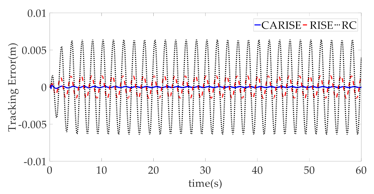
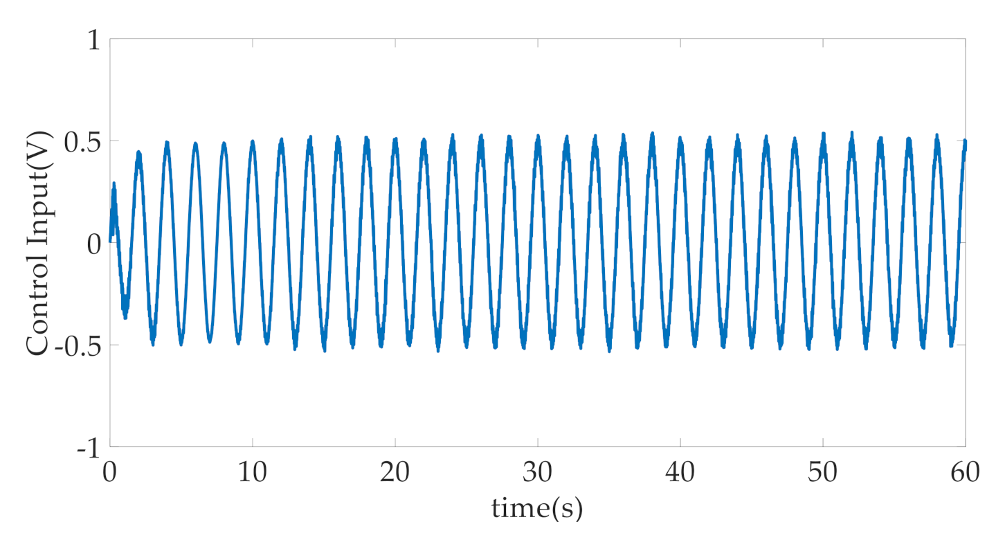
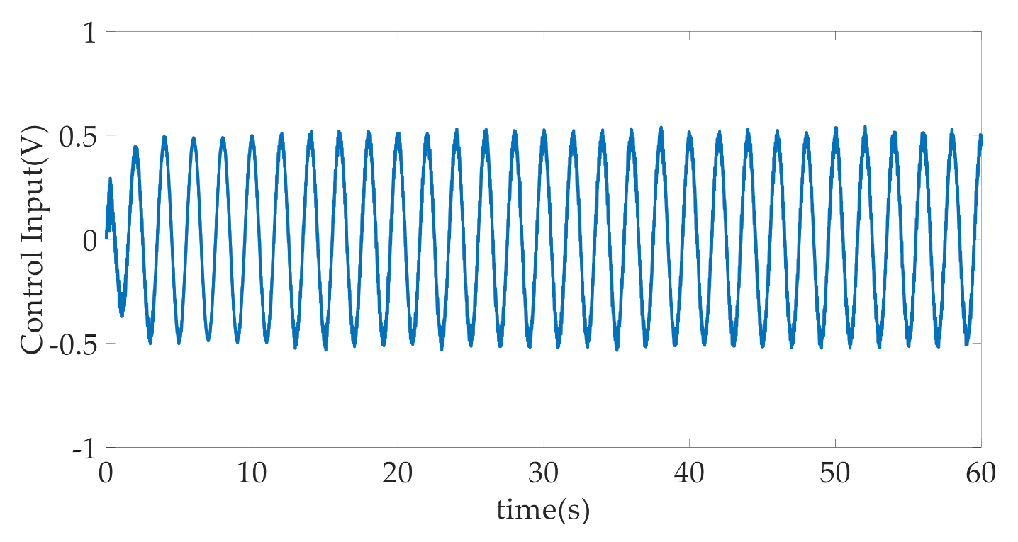
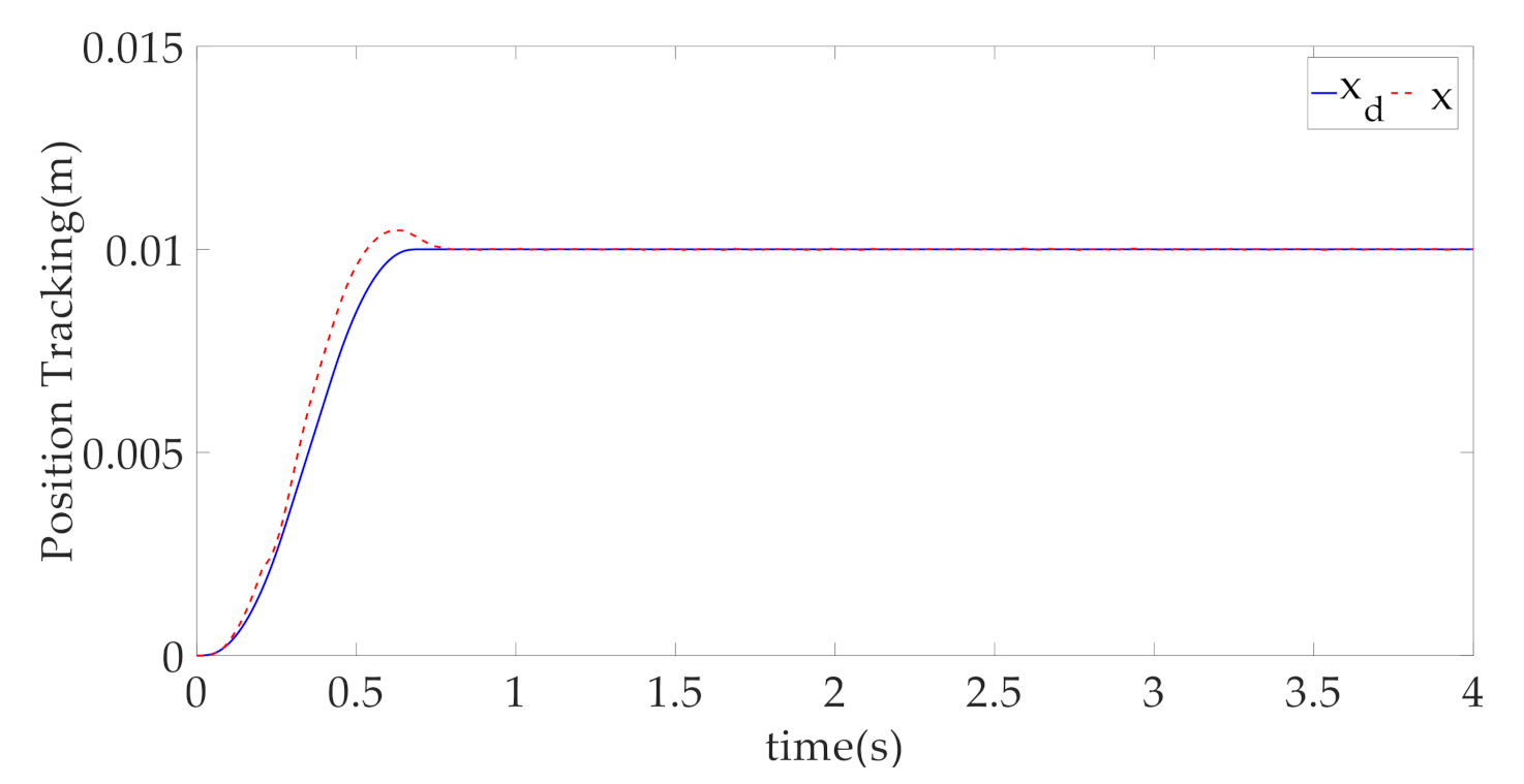
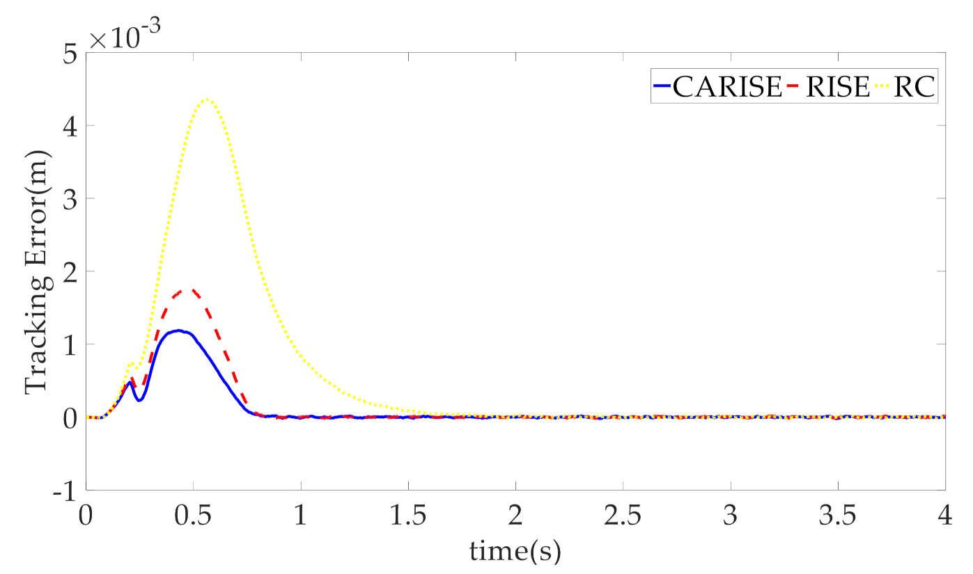
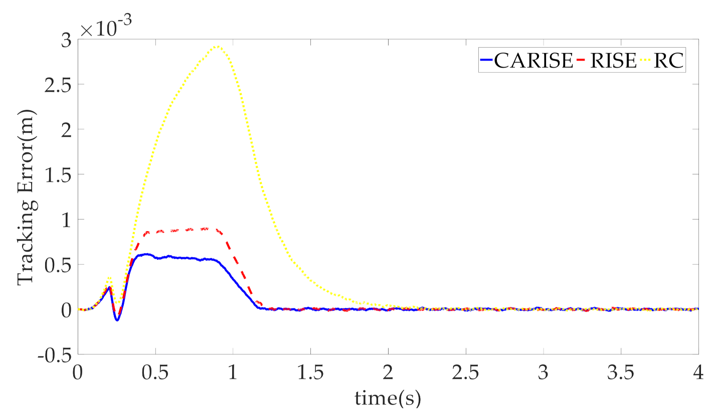
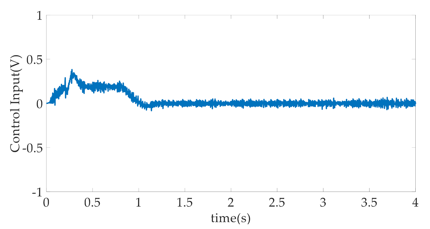
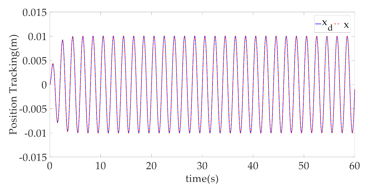
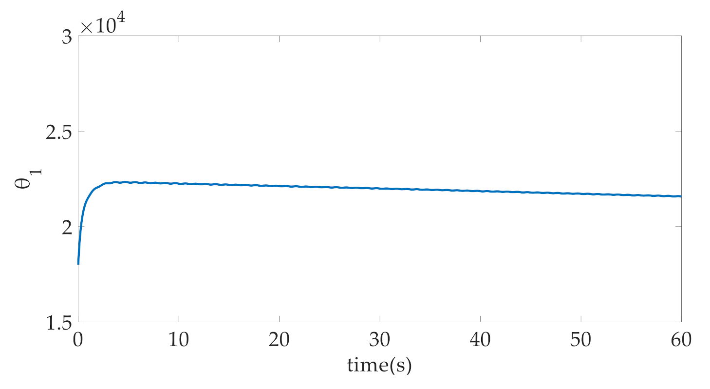
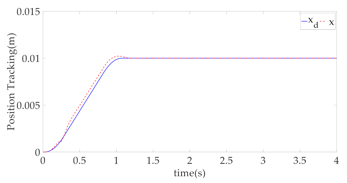
4. Simulation Results and Discussion

The physical parameters of the EHA system are shown in Table 1. The simulated EHA system relies on a servo motor to drive the plunger pump. The plunger pump provides the flow and pressure matching the load to the hydraulic cylinder, and pushes the load mass block to move.
The following three controllers are compared to verify the effectiveness of the proposed controller in this section.
(1)
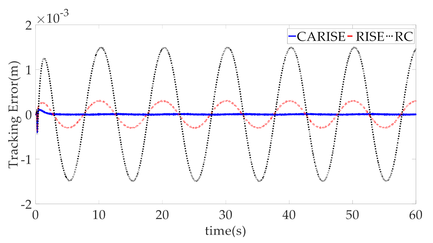
CARISE: The RISE-based composite adaptive controller is proposed in this paper and described in Section 3, whose control parameters are given by k 1 = 400 , k 2 = 10 00 , k 3 = 2 , k r = 8 , Γ = d i a g { 5 , 1000 , 0.01 } , k = 0 . 01 , j = 1 , β = 1 and θ ^ ( 0 ) = [ 18000 ; 4 × 10 5 ; 10 ] .
(2)
RISE: This is the RISE-based controller without the composite adaptive law. In order to ensure the fairness of the comparison, the controller parameters k 1 , k 2 , k 3 , k r , β and θ ^ ( 0 ) are the same as CARISE, and adaptive gain matrix and other relevant parameters are given by Γ = d i a g { 0 , 0 , 0 } , k = 0 , j = 0 .
(3)
RC: This is the linear robust controller introduced in [32]. Additionally, for the convenience of comparing the controller performance, the parameters are the same as CARISE. Therefore, the controller parameters k 1 , k 2 , k 3 and θ ^ ( 0 ) are the same as CARISE, and RISE gain coefficients and adaptive gain coefficients are given by k r = 0 , β = 0 , Γ = d i a g { 0 , 0 , 0 } , k = 0 , j = 0 .
Case 1: The desired position trajectory x d = 0.01 sin ( 3.14 t ) ( 1 e t ) m is first implemented, as shown in Figure 3. In this case, the tracking errors of the three controllers can be seen from Figure 4. The simulation results show that the transient tracking performance and steady-state tracking performance of the CARISE controller are superior to the other two controllers. As presented, the tracking performance of the RISE controller without parameter adaptation is worse than that of the CARISE controller. This is because the composite adaptive method can make the estimated parameters converge to their true values, which eliminates the influence of the velocity loop error of the servo motor, remaining parameter uncertainties and unmodeled dynamics on the tracking performance of the EHA system, thus proving the effectiveness of the indirect adaptive method. In addition, the transient and steady-state tracking performance of the RISE controller is better than that of the RC controller, which indicates that the nonlinear feedback controller of RISE is more robust than the RC controller. The CARISE control strategy combines the composite adaptive control method with the RISE-based high-gain controller to achieve the optimal control performance among the three controllers, while ensuring asymptotic stability under parameter uncertainties and unmodeled dynamics. Parameter adaptation of the CARISE controller is shown in Figure 5. The results show that all the estimated parameters tend to be stable. The velocity loop error of the servo motor is shown in Figure 6. The error is bounded. The control input is shown in Figure 7. Its value is also bounded, which is good for practical implementation. Simulation results show that the proposed algorithm in case 1 is effective.
Case 2: In order to further verify the effectiveness of the proposed method, another frequency position trajectory x d = 0.01 sin ( 0.628 t ) ( 1 e t ) m is performed. In this case, the position tracking trajectory of the CARISE controller is shown in Figure 8. Comparison of the tracking errors of the three controllers is shown in Figure 9. Obviously, the transient and steady-state tracking performance of the CARISE controller is superior to the other two controllers in this condition. The simulation results show that the CARISE control strategy using the composite adaptive law and RISE nonlinear feedback controller is still effective under the lower frequency tracking command. The control input of CARISE in case 2 is shown in Figure 10. The voltage amplitude is less than 0.6 V, which is conducive to practical realization. Therefore, the comparative simulation results in this case again guarantee the effectiveness of CARISE.
Case 3: In order to further verify the control performance of the proposed controller, the curve in Figure 11 is selected as the desired trajectory input. The desired trajectory shown in Figure 11 is a fast point–point motion trajectory, which has a maximum velocity of 0.025 m/s and a maximum acceleration of 0.1 m/s2. In this case, the position tracking trajectory of the CARISE controller is shown in Figure 11. Comparison of the tracking errors of the three controllers is shown in Figure 12. Obviously, the transient tracking performance of the CARISE controller is superior to the other two controllers in this condition. However, the steady-state tracking performance of the three controllers has little difference when reaching a steady state. The simulation results show that the CARISE control strategy using the composite adaptive law and RISE nonlinear feedback controller is still effective under a fast point–point motion trajectory. However, the improvement of transient tracking performance of the CARISE controller is much lower than that of the sinusoidal trajectory. The control input of CARISE in case 3 is shown in Figure 13. The voltage amplitude is less than 0.6 V, which is conducive to practical realization. To sum up, when tracking the trajectory in case 3, the controller proposed in this paper can improve the transient tracking performance to a certain extent, but has little improvement on the steady-state tracking performance.
Case 4: In this case, we choose a desired trajectory that is slower than in case 3. The trajectory shown in Figure 14 is a slow point–point motion trajectory, which has a maximum velocity of 0.0125 m/s and a maximum acceleration of 0.05 m/s2. In this case, the position tracking trajectory of the CARISE controller is shown in Figure 14. Comparison of the tracking errors of the three controllers is shown in Figure 15. Obviously, the transient tracking performance of the CARISE controller in case 4 is superior to the other two controllers in this condition. However, the steady-state tracking performance of the three controllers has little difference when reaching a steady state, which is consistent with the conclusion in case 3. At the same time, because the trajectory motion speed slows down, the tracking errors of the three controllers are all smaller than those in case 3. The simulation results show that the CARISE control strategy using the composite adaptive law and RISE-based nonlinear feedback controller is still effective under a slow point–point motion trajectory. The control input of CARISE in case 4 is shown in Figure 16. The voltage amplitude is less than 0.5 V, which is conducive to practical realization. To sum up, the simulation results show that the proposed CARISE controller can still improve the transient control performance when tracking a slow point–point motion trajectory, and the improvement amplitude is larger than that of case 3.

5. Conclusions

For the EHA system, the velocity loop error of servo motors, parameter uncertainties and unmodeled dynamics exist in large quantities, which limit the improvement of its control performance. In this paper, according to the EHA schematic diagram, the dynamic equation and pressure dynamic equation of the EHA system are established. Based on the established equation of states, a RISE-based composite adaptive control method has been proposed. The composite adaptive law is used to deal with the parameter uncertainties and to improve the parameter convergence speed. At the same time, the speed loop error of servo motors and unmodeled dynamics are treated with a RISE-based high-gain controller. This control algorithm can ensure asymptotic tracking stability, and has higher transient tracking accuracy compared with other simulation algorithms in this paper, which provides an effective approach for the study of EHA nonlinear control strategies. As future work, this is worthy of further in-depth experimental exploration in practical applications.

Author Contributions

Formal analysis, Y.G. and X.Y.; Investigation, W.D. and J.Y.; Methodology, Y.G. and J.Y.; Project administration, W.D.; Writing—original draft, Y.G. All authors have read and agreed to the published version of the manuscript.

Funding

This research was supported in part by the National Natural Science Foundation of China (51905271, 52075262), in part by the Natural Science Foundation of Jiangsu Province (BK20190459) and in part by the Fundamental Research Funds for the Central Universities (30920041101).

Institutional Review Board Statement

Not applicable.

Informed Consent Statement

Not applicable.

Data Availability Statement

Not applicable.

Conflicts of Interest

The authors declare no conflict of interest.

References

  1. Yao, J.; Jiao, Z.; Yao, B.; Shang, Y.; Dong, W. Nonlinear adaptive robust force control of hydraulic load simulator. Chin. J. Aeronaut. 2012, 25, 766–775. [Google Scholar] [CrossRef] [Green Version]
  2. Chen, Z.; Yuan, Y.; Yuan, X.; Huang, Y.; Li, X.; Li, W. Application of multi-objective controller to optimal tuning of PID gains for a hydraulic turbine regulating system using adaptive grid particle swam optimization. ISA Trans. 2015, 56, 173–187. [Google Scholar] [CrossRef] [PubMed]
  3. Merritt, H. Hydraulic Control Systems; John Wiley & Sons: New York, NY, USA, 1967. [Google Scholar]
  4. Li, L.; Lin, Z.; Jiang, Y.; Yu, C.; Yao, J. Valve deadzone/backlash compensation for lifting motion control of hydraulic manipulators. Machines 2021, 9, 57. [Google Scholar] [CrossRef]
  5. Formato, G.; Romano, R.; Formato, A.; Sorvari, J.; Koiranen, T.; Pellegrino, A.; Villecco, F. Fluid-structure interaction modeling applied to peristaltic pump flow simulations. Machines 2019, 7, 50. [Google Scholar] [CrossRef] [Green Version]
  6. Gusustavo, C.; Nariman, S. Hydrostatic Transmissions and Actuators; Wiley: New York, NY, USA, 2015. [Google Scholar]
  7. Joel, R.S. The F-18 Systems Research Aircraft Facility; NASA Technical Memorandum; NASA: Hampton, VA, USA, 1992.
  8. Robert, N. Performance of an Electro-Hydrostatic Actuator on the F-18 Systems Research Aircraft; NASATM-97-206224; NASA: Hampton, VA, USA, 1997.
  9. Stephen, C.J. Flight Test Experience with an Electromechanical Actuator on the F-18 Systems Research Aircraft; NASA: Hampton, VA, USA, 1998.
  10. Tessari, F.; Galluzzi, R.; Tonoli, A.; Amati, N.; Milandri, G.; Laffranchi, M.; De Michieli, L. An integrated, back-drivable electro-hydrostatic actuator for a knee prosthesis. In Proceedings of the 8th IEEE RAS/EMBS International Conference for Biomedical Robotics and Biomechatronics, New York, NY, USA, 29 November–1 December 2020; pp. 708–714. [Google Scholar] [CrossRef]
  11. Hyon, S.H.; Tanimoto, S.; Asao, S. Toward compliant, fast, high-precision, and low-cost manipulator with hydraulic hybrid servo booster. In Proceedings of the 2017 IEEE International Conference on Robotics and Automation (ICRA), Singapore, 29 May–3 June 2017; pp. 39–44. [Google Scholar]
  12. Huang, L.; Yu, T.; Jiao, Z.; Li, Y. Active load-sensitive electro-hydrostatic actuator for more electric aircraft. Appl. Sci. 2020, 10, 6978. [Google Scholar] [CrossRef]
  13. Habibi, S.; Goldenberg, A. Design of a new high performance electrohydraulic actuator. In IEEE/ASME International Conference on Advanced Intelligent Mechatronics; AIM: New York, NY, USA, 1999; pp. 227–232. [Google Scholar]
  14. Li, Y.; Jiao, Z.; Wang, Z. Design, analysis, and verification of an electro-hydrostatic actuator for distributed actuation system. Sensors 2020, 20, 634. [Google Scholar] [CrossRef] [Green Version]
  15. Helian, B.; Chen, Z.; Yao, B. Precision motion control of a servomotor-pump direct-drive electrohydraulic system with a nonlinear pump flow mapping. IEEE Trans. Ind. Electron. 2020, 67, 8638–8648. [Google Scholar] [CrossRef]
  16. Zheng, J.M.; Zhao, S.D.; Wei, S.G. Application of self-tuning fuzzy PID controller for a SRM direct drive volume control hydraulic press. Control Eng. Pract. 2009, 17, 1398–1404. [Google Scholar] [CrossRef]
  17. Peng, Y.G.; Wang, J.; Wei, W. Model predictive control of servo motor driven constant pump hydraulic system in injection molding process based on neurodynamic optimization. J. Zhejiang Univ. Sci. C 2014, 15, 139–146. [Google Scholar] [CrossRef]
  18. Ding, R.; Zhang, J.; Xu, B.; Cheng, M.; Pan, M. Energy efficiency improvement of heavy-load mobile hydraulic manipulator with electronically tunable operating modes. Energy Convers. Manag. 2019, 188, 447–461. [Google Scholar] [CrossRef]
  19. Lin, Y.; Shi, Y.; Burton, R. Modeling and robust discrete-time sliding-mode control design for a fluid power electrohydraulic actuator (EHA) system. IEEE/ASME Trans. Mechatron. 2013, 18, 1–10. [Google Scholar] [CrossRef]
  20. Hyon, S.H.; Taniai, Y.; Hiranuma, K.; Yasunaga, K.; Mizui, H. Overpressure Compensation for Hydraulic Hybrid Servo Booster Applied to Hydraulic Manipulator. IEEE Robot. Autom. Lett. 2019, 4, 942–949. [Google Scholar] [CrossRef]
  21. Ahn, K.K.; Nam, D.N.C.; Jin, M. Adaptive backstepping control of an electrohydraulic actuator. IEEE/ASME Trans. Mechatron. 2014, 19, 987–995. [Google Scholar] [CrossRef]
  22. Hippalgaonkar, R.; Ivantysynova, M. Optimal power management of hydraulic hybrid mobile machines-Part I: Theoretical studies, modeling and simulation. J. Dyn. Syst. Meas. Control Trans. ASME 2016, 138, 1–23. [Google Scholar] [CrossRef]
  23. Xian, B.; Dawson, D.M.; de Queiroz, M.S.; Chen, J. A continuous asymptotic tracking control strategy for uncertain nonlinear systems. IEEE Trans. Automat. Contr. 2004, 49, 1206–1211. [Google Scholar] [CrossRef]
  24. Yao, J.; Jiao, Z.; Ma, D.; Yan, L. High-accuracy tracking control of hydraulic rotary actuators with modeling uncertainties. IEEE/ASME Trans. Mechatron. 2014, 19, 633–641. [Google Scholar] [CrossRef]
  25. Yao, J.; Deng, W.; Jiao, Z. RISE-Based Adaptive Control of Hydraulic Systems with Asymptotic Tracking. IEEE Trans. Autom. Sci. Eng. 2017, 14, 1524–1531. [Google Scholar] [CrossRef]
  26. Deng, W.; Yao, J. Adaptive integral robust control and application to electromechanical servo systems. ISA Trans. 2017, 67, 256–265. [Google Scholar] [CrossRef]
  27. Tatlicioglu, E. Adaptive control of non-linear teleoperation systems in the presence of additive input and output disturbances. Int. J. Robot. Autom. 2010, 25, 17–25. [Google Scholar]
  28. Peng, C.C.; Chen, C.L. Dynamic controller design for a class of nonlinear uncertain systems subjected to time-varying disturbance. Nonlinear Dyn. 2009, 57, 411–423. [Google Scholar] [CrossRef]
  29. Xu, Y.; Mohseni, K. Bioinspired hydrodynamic force feedforward for autonomous underwater vehicle control. IEEE/ASME Trans. Mechatron. 2014, 19, 1127–1137. [Google Scholar] [CrossRef] [Green Version]
  30. Cui, L.; Zhang, H.; Bing, C.; Zhang, Q. Asymptotic tracking control scheme for mechanical systems with external disturbances and friction. Neurocomputing 2010, 73, 1293–1302. [Google Scholar] [CrossRef]
  31. Yang, C.; Jiang, Y.; He, W.; Na, J.; Li, Z.; Xu, B. Adaptive parameter estimation and control design for robot manipulators with finite-time convergence. IEEE Trans. Ind. Electron. 2018, 65, 8112–8123. [Google Scholar] [CrossRef]
  32. Yang, X.; Yao, J.; Deng, W. Output feedback adaptive super-twisting sliding mode control of hydraulic systems with disturbance compensation. ISA Trans. 2021, 109, 175–185. [Google Scholar] [CrossRef] [PubMed]
Figure 1. The schematic diagram of the electro-hydrostatic actuator (EHA).
Machines 09 00181 g001
Figure 2. The flow diagram of robust integral of the sign of error (RISE)-based composite adaptive controller.
Machines 09 00181 g002
Figure 3. The position tracking of CARISE in case 1.
Machines 09 00181 g003
Figure 4. The tracking errors of three controllers in case 1.
Machines 09 00181 g004
Figure 5. The composite parameter adaption of CARISE.
Machines 09 00181 g005aMachines 09 00181 g005b
Figure 6. The velocity loop error of servo motor zm in case 1.
Machines 09 00181 g006
Figure 7. Control input of CARISE in case 1.
Machines 09 00181 g007
Figure 8. The position tracking of CARISE in case 2.
Machines 09 00181 g008
Figure 9. The tracking errors of three controllers in case 2.
Machines 09 00181 g009
Figure 10. Control input of CARISE in case 2.
Machines 09 00181 g010
Figure 11. The position tracking of CARISE in case 3.
Machines 09 00181 g011
Figure 12. The tracking errors of three controllers in case 3.
Machines 09 00181 g012
Figure 13. Control input of CARISE in case 3.
Machines 09 00181 g013
Figure 14. The position tracking of CARISE in case 4.
Machines 09 00181 g014
Figure 15. The tracking errors of three controllers in case 4.
Machines 09 00181 g015
Figure 16. Control input of CARISE in case 4.
Machines 09 00181 g016
Table 1. Physical parameters of the EHA system.
ParameterValueParameterValue
m (kg)30V01 (m3)3.981 × 10⁻⁵
B ( N / ( m s ) )400D (cc/rev)18
A (m2)9.0478 × 10⁻⁴km (rpm/V)200
Publisher’s Note: MDPI stays neutral with regard to jurisdictional claims in published maps and institutional affiliations.

