Article

Stability Analysis of a Fractional-Order High-Speed Supercavitating Vehicle Model with Delay

1
Nguyen Tat Thanh Hi-Tech Institute, Nguyen Tat Thanh University, Ho Chi Minh City 754000, Vietnam
2
Department of Mechanical Engineering, The University of Tulsa, 800 S. Tucker Drive, Tulsa, OK 74104, USA
3
School of Intelligent Mechatronics Engineering, Sejong University, 98 Gunja-dong, Gwangjin-gu, Seoul 143-747, Korea
4
Department of Mechatronics Engineering, Ho Chi Minh City University of Technology and Education, Ho Chi Minh City 700000, Vietnam
5
Department of Industrial and Production Engineering, Jashore University of Science and Technology, Jashore 7408, Bangladesh
*
Author to whom correspondence should be addressed.
Machines 2021, 9(7), 129; https://doi.org/10.3390/machines9070129
Submission received: 20 May 2021 / Revised: 11 June 2021 / Accepted: 13 June 2021 / Published: 24 June 2021
(This article belongs to the Special Issue Dynamics and Motion Control of Unmanned Aerial/Underwater Vehicles)

Abstract

:
A novel fractional-order model (FOM) of a high-speed super-cavitating vehicle (HSSV) with the nature of memory is proposed and investigated in this paper. This FOM can describe the behavior of the HSSV superior to the integer-order model by the memory effects of fractional-order derivatives. The fractional order plays the role of the advection delay, which is ignored in most of the prior studies. This new model takes into account the effect of advection delay while preserving the nonlinearity of the mathematical equations. It allows the analysis of nonlinear equations describing the vehicle with ease when eliminating the delay term in its equations. By using the fractional order to avoid the approximation of the delay term, the proposed FOM can also preserve the nature of the time delay. The numerical simulations have been carried out to study the behavior of the proposed model through the transient responses and bifurcation diagrams concerning the fractional-order and vehicle speed. The bifurcation diagrams provide useful information for a better control and design of new supper super-cavitating vehicles. The similar behaviors between the proposed model and prior ones validate the FOM while some discrepancies suggest that more appropriate controllers should be designed based on this new model.

1. Introduction

High-speed super-cavitating vehicle (HSSV) is a special class of underwater vehicles that can move at speeds much higher than usual by exploiting super-cavitating technology. The extremely high speed of the HSSV is due to skin-friction drag reduction caused by a sufficient air bubble that almost envelops the vehicle body. The big air bubble is formed by a proper design of a cavitator installed at the nose of the vehicle. This cavitator has a cone or rounded-flat shape with a sharp edge and can change its deflection angle to create a supporting force for the vehicle. The sharp edge of the cavitator is designed to create a large pressure gradient at high speed that forms the super-cavity [1]. The HSSV is propelled by a super-cavitating propeller and the vehicle can change its directions by deflection angles of the cavitator in the front and the fins in the aft. A configuration diagram of an HSSV is illustrated in Figure 1.
The working principle of the HSSV raises challenges for the modeling, analysis, and control of the vehicle due to complex interactions between the vehicle and the cavity, non-linear planing forces, and memory effects [2]. There have been several studies about the HSSV modeling with different degree-of-freedom (DOF) such as the one-DOF model of Kirschner et al. [3], the two-DOF model of Dzielski and Kurdila [4], the four-DOF model used to study pitch-plane dynamics [5], the six-DOF model [6], and the 12-DOF model [7]. Some other models include the numerical model incorporating structural elasticity [8], and the models that account for the non-cylindrical cavity effects [9].
In most prior studies, time-delay effects have been ignored. There are only a few articles that have considered advection delay in their studies such as [1,2]. This delay is defined as the short time for actions from the cavitator in the front to be transmitted to the aft. It means when the advection delay is considered, the current states of the HSSV depend on its previous states. It also has been pointed out that the dynamic of delay-free models and the models with advection delay, i.e., the delayed model, have some different behaviors, hence the controllers designed for the former models may not works for the real HSSV with existing advection delay [2]. However, since the delay only has effects on the non-linear planing force, which is noncontinuous, the analysis of the models with advection delay will be challenged and the non-linear model may have to be linearized before analyzing.
Although fractional calculus has more than 300 years of history but in recent years, its applications have been rapidly grown. It is because of the blossom of approximation methods and the growing number of complex physical systems whose behaviors can be better described by fractional-order theory such as in signal processing [10,11], bioengineering [12,13], hydrology [14], economic processes [15], heat conduction through a semi-infinite solid [16], and chaos [17,18]. In some cases, the fractional-order models (FOM) seem to be more consistent with the real phenomena than the integer-order models. This is because fractional derivatives and integrals enable the description of the memory and hereditary properties inherently in various materials and processes [19].
In this study, based on an integer-order model, a fractional-order HSSV (FOHSSV) model is proposed which can memorize a short history of the vehicle states. The modelling of the HSSV by fractional-order differential equation has more advantages than the old integer-order model, in which the memory effects are neglected. The FOHSSV can take into account the effect of advection delay by its fractional-order while preserving the non-linear behavior of system analysis and control. It provides convenience when analyzing the vehicle with different delay times by adjusting the fractional-order of the model. The proposed model provides a better description for the HSSV and more appropriate controllers can be investigated based on this model.

2. Materials and Methods

2.1. Fractional Calculus

Fractional calculus is a generalization of integration and differentiation to a non-integer order fundamental operator D   t a a defined as in [20]:
D   t a a = { d α / d t α ( α > 0 ) 1 ( α = 0 ) a t ( d τ ) α ( α < 0 )
where, α > 0 one obtains differentiators while, α < 0 yields integrators, a and t are the limits of the operator.
There are some definitions for the general fractional operator. The most common ones include Caputo and Riemann-Liouville definition, which are respectively, represented as follows.
D t β α f ( t ) = 1 Γ ( n β ) α t f ( n ) ( ζ ) ( t ζ ) β n + 1 d ζ
D t β α f ( t ) = ( d d t ) n 1 Γ ( n β ) α t f ( n ) ( ζ ) ( t ζ ) β n + 1 d ζ
where, n 1 β n ; n is the smallest integer that is greater than or equal to β . By using β , which is non-integer order, the mathematical model can possibly capture more dynamics of the system. Γ is the Gamma function defined as:
Γ ( n ) = 0 t n 1 e t d t

2.2. Mathematical Models and Behavior of the HSSV

2.2.1. Integer-Order Mathematical Model

The HSSV control surfaces include the fins surface and the cavitator. The control surfaces support the vehicle in the vertical direction by providing lift forces, and allow maneuvering by their deflection angles [7]. In this work, the dive-plane dynamics of an HSSV is introduced in Figure 1 which is similar to the dynamic model proposed by Dzielski and Kurdila [4]. The integer-order model is based on the total mass and moment acting on the vehicle. The equations of motion are written around the vehicle center of gravity inspired by [1], where the vehicle mass can be calculated by:
M = 7 9 m ρ π R 2 L
where, m is the relative density between uniform body density ( ρ b ) and surrounding water density ( ρ ), R indicates the vehicle body radius and L represents the vehicle length.
The equation for vehicle moment of inertia is:
I y y = 11 60 R 4 L m ρ π + 1933 45360 R 2 L 3 m ρ π
The forces acting on the vehicle are lift forces i.e. Fc and Ff caused by the cavitator and the fins, the gravity force Fg, and the noncontiuous planing force Fp. The equation for each force is provided as follows. First, the lift force caused by the cavitator is calculated as:
F c = 1 2 π ρ R n 2 V 2 C x α c = C l α c
where, the cavitator drag coefficient C x = C x 0 ( 1 + σ ) , in which σ is the cavitation number and C x 0 = 0.82 [21], Rn is the cavitator radius, V is the vehicle forward speed and α c is the attack angle of the cavitator.
There are four fins installed in the aft of the HSSV. Only the two side fins provide lift force to support the vehicle. In dive-plane dynamics, the side fins will turn the same deflection angles when acting as the actuator in the aft side. The lift force caused by the two side fins is calculated as:
F f = n   C l   α f
where, n indicates the fins’ effectiveness in providing lift and α f denotes the attack angle of the fins.
The equation to calculate the planing force Fp is quite complicated. Therefore, to simplify the equations describing the planing force, the following intermediate constants are firstly defined as:
K 1 = L R n ( 1.92 σ 3 ) 1 , K 2 = 1 ( 1 4.5 σ 1 + σ ) K 1 40 / 17
Then, the normalized planing force can be calculated by the following equation:
F p = V 2 [ 1 ( R c R h R + R c R ) 2 ] 1 + h 1 + 2 h α v
where, Rc is the diameter of the cavity at the planing location which can be calculated as:
R c = R n 0.82 1 + σ σ K 2
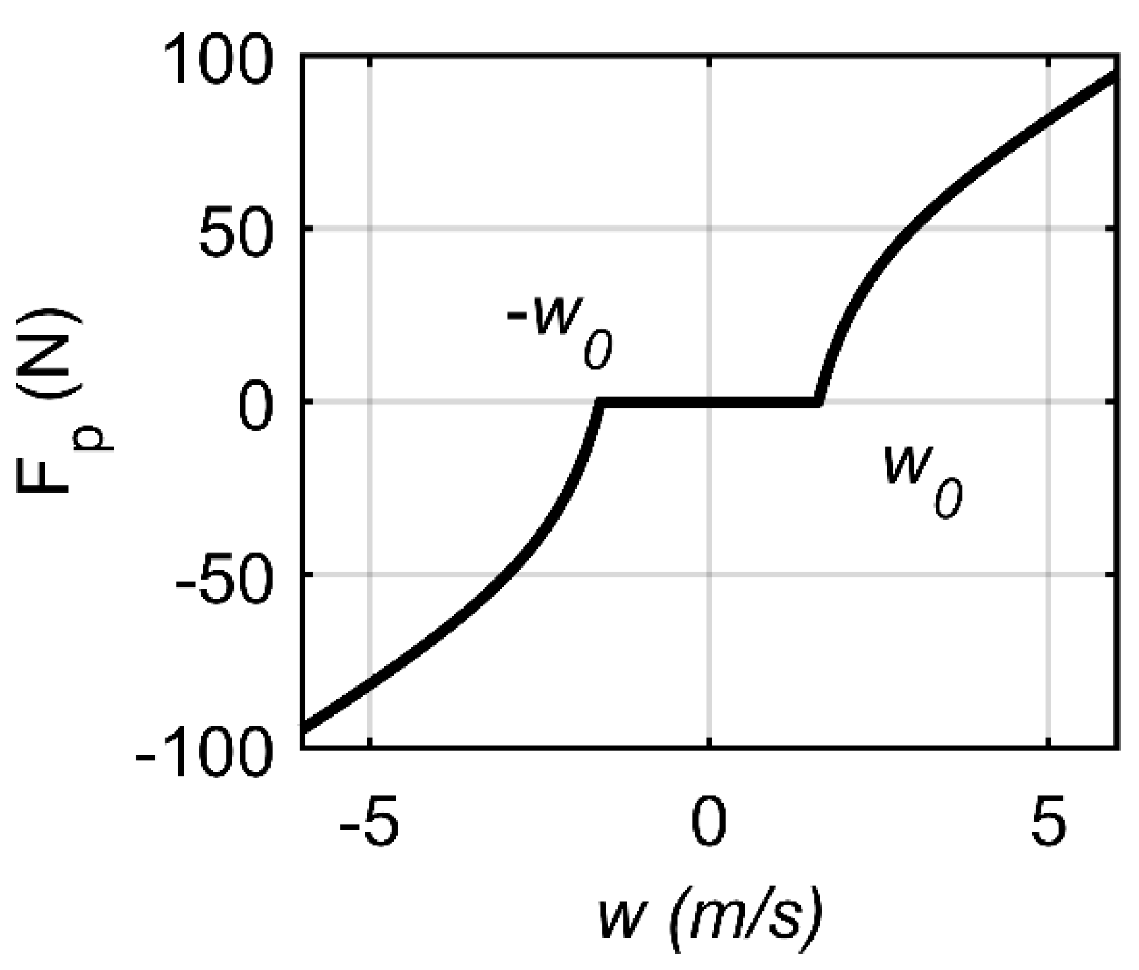
The term h is the normalized immersion depth, α v is the immersion angle and they are discontinuous functions calculated as the following, respectively, and are graphically illustrated in Figure 1.
h = { h * R c R R , h * > R c R R h * R c R R , h * > R c R R 0 , | h * | R c R R
α v = { w R ˙ c V , h * > R c R R w + R ˙ c V   , h * > R c R R 0 , | h * | R c R R
where ,   h * = L w R V
In Equations (12) and (13), R c is the contraction rate of the super-cavity evaluated as:
R ˙ c = 1.176 ( 0.82 1 + σ σ ) V ( 1 4.5 σ 1 + σ ) K 1 23 / 17 K 2 ( 1.92 σ 3 )
Then, the total forces and moments around the HSSV’s center of gravity are calculated as:
M w ˙ = F c + F f + F g + F p
I y y q ˙ = ( F c L c + F f L f + F p L f )
where, Lc = 17/28L and Le = −11/28L are the moment arm of the cavitator and fin forces, respectively. For simplicity, the planing force is assumed to act at the same position as fin forces.
Finally, based on some references [2,5], the integer-order governing equation in the body frame describing the vehicle dynamics can be written in the form of a switched system with state-dependent switching boundaries [22] (Liberzon, 2003) as follows:
[ z ˙ w ˙ θ ˙ q ˙ ] = [ 0 1 V 0 0 a 22 0 a 24 0 0 0 1 0 a 42 0 a 44 ] [ z w θ q ] + [ 0 b 21 0 b 41 0 b 22 0 b 42 ] [ δ f δ c ] + [ 0 g 0 0 ] + [ 0 d 2 0 d 4 ] F p
where, the partial components are given as:
x = [ z w θ q ] , u = [ δ f δ c ]
A = [ 0 1 V 0 0 a 22 0 a 24 0 0 0 1 0 a 42 0 a 44 ] , B = [ 0 b 21 0 b 41 0 b 22 0 b 42 ]
G = [ 0 F g 0 0 ] , F = [ 0 d 2 F p 0 d 4 F p ]
where, the partial elements of A, B, and F are given in Appendix A and the related parameters are given in Appendix B.
The four state variables of the vehicle model include the vertical position z, the vertical speed w, the pitch angle θ and the pitch rate q. The direction of the HSSV is controlled through the deflections of the fin deflection angle δf in the aft and the cavitator deflection angle δc in the front part. This model ignores the advection delay and takes into account the non-linear planing force, which describes the non-linear interaction between the body and the liquid out of cavity and a simplified description of the cavity dynamics [23].

2.2.2. The Non-linear Planing Force and Advection Delay

From Equations (10), (12) and (13), the planing force is realized as a non-linear noncontinuous force. The relation between the normalized planing force and vertical speed w is shown in Figure 2. It can be observed that this force only occurs if the magnitude of the vertical velocity w is greater than wo, where the vehicle aft end pierces the super-cavity and contacts with water as illustrated in Figure 1. The force can cause vibration, shocks, and has the tendency of pushing the vehicle aft end toward the center of the super-cavity. Depending on the strength of the tail-moment generated by the planing force, the vehicle may be suffered from the tail-slap condition, when repeating shocks occur due to the contacts between the vehicle tail and the cavity wall in opposite sides.
When the HSSV moves forward, there is a delay time for actions at the cavitator to be transmitted to the aft of the vehicle where planing occurs. Due to the delay, the size and position of the super-cavity are determined by the previous position of the cavitator attached at the nose of the HSSV. The delay was mentioned as advection delay as in [2] and is represented as:
τ = L V
Since the original delay-free model does not consider this advection delay, there are differences between the planing behaviors of the delay-free model and the delayed model. The immersion depth and immersion angle with advection delay are calculated as [2]:
h = { h * R c R R , h * > R c R R h * R c R R , h * > R c R R 0 , | h * | R c R R
α v = { θ ( t ) θ τ + w τ R ˙ c V , h * > R c R R θ ( t ) θ τ + w + R ˙ c V h * > R c R R 0 , | h * | R c R R
where,
h * = z ( t ) z τ + L ( θ ( t ) θ τ ) + L w τ / V R
Comparing Equations (23,24) and Equations (12,13), it is observed that they are identical when the advection delay τ is zero. When the advection delay is not zero, the normalized immersion depth and immersion angle have to take into account the history of the vehicle states including vertical position, pitch angle and vertical speed.
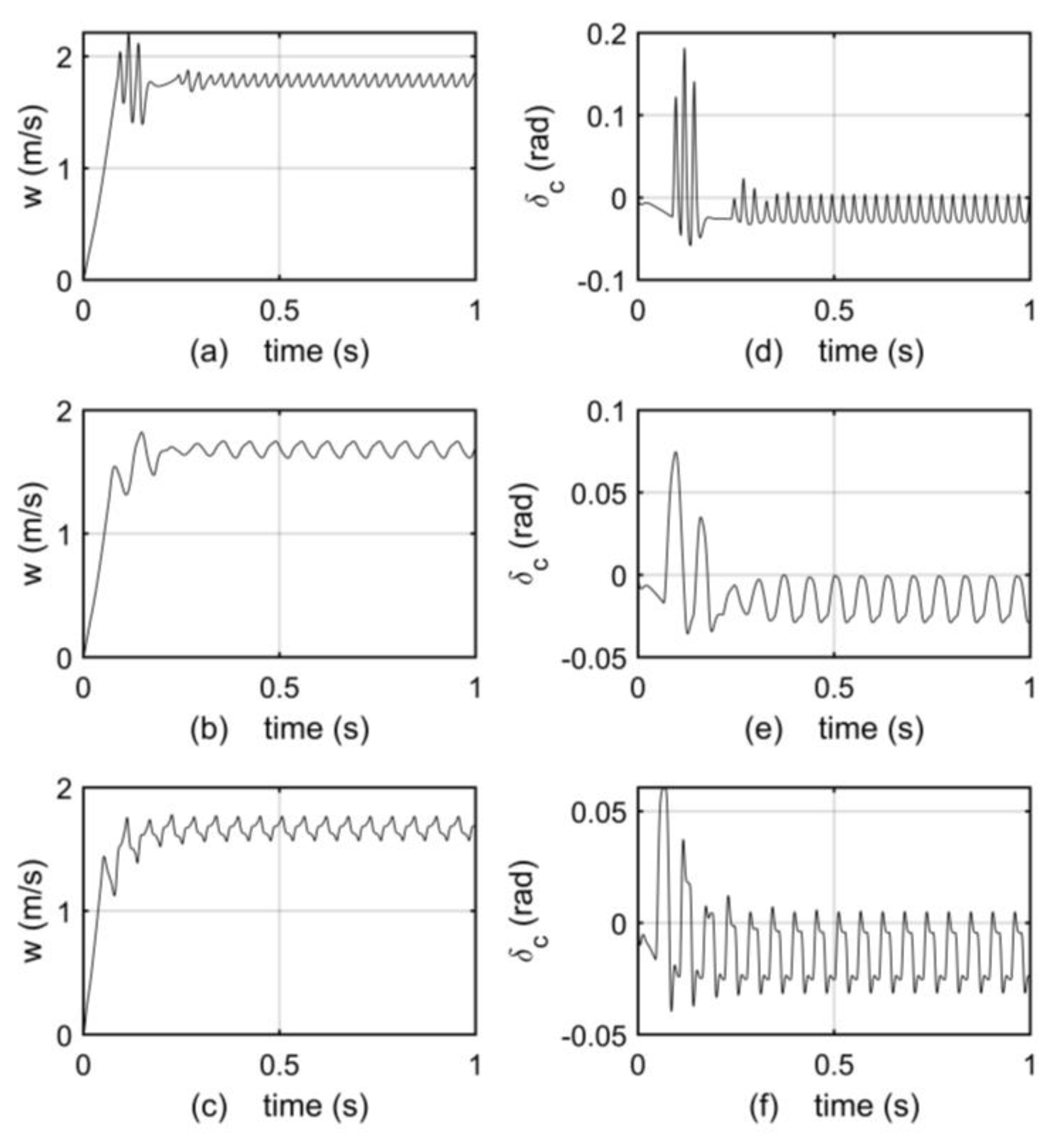
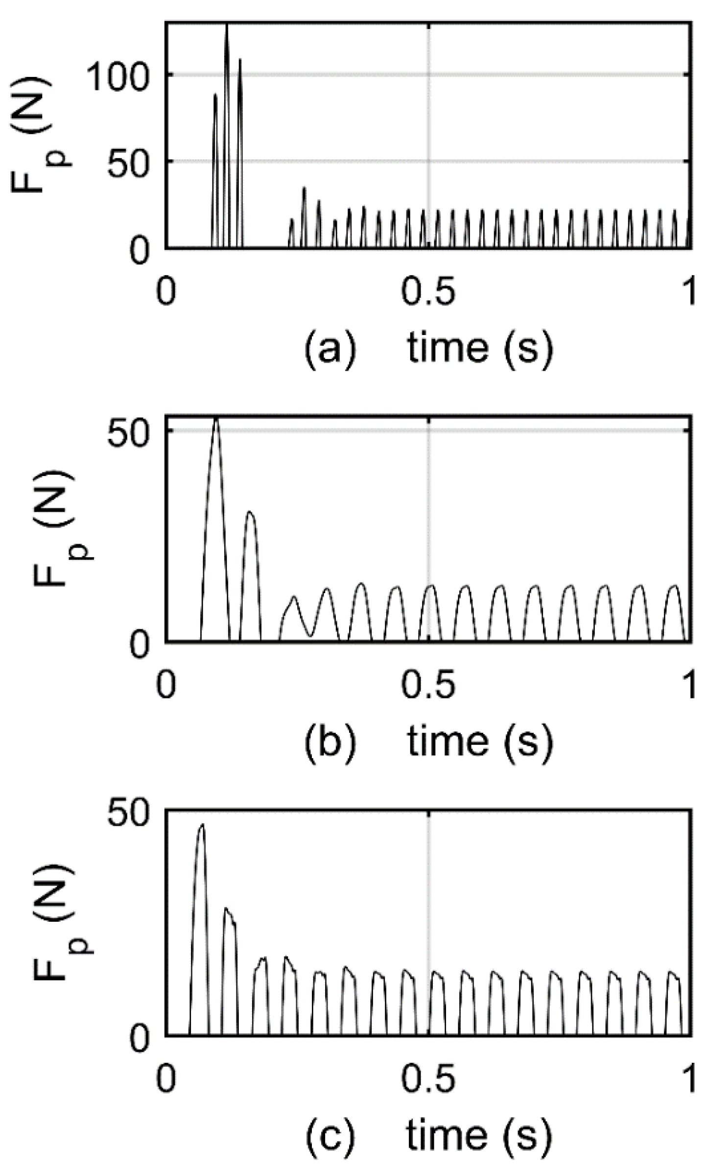
The depth response of the delay-free model and the delayed model are illustrated in Figure 3a,b. It clearly indicates that the delayed model exhibits a slower response with lower frequency content than the delay-free one. It is the result of lower frequency planing force in the delayed model compared with its counterpart, as shown in Figure 4a and Figure 4b, respectively. The simulation demonstrated that the controllers used for the delay-free model may not be feasible for the delayed model, which is closer to the real system.

2.2.3. The Fractional-Order Mathematical Model

In order to analyze the non-linear model with advection delay τ in the work of Munther et al. [2], the authors have to linearize the non-linear model at a stable operating point, using the theory of time-delay systems. The linearization may eliminate some characteristics of the original non-linear model. Hence, there is still a gap between the linearized and the non-linear one and the analyzed result of the linearized system is only a local result [2]. In order to preserve the non-linearity while accounting for the advection delay, considering the memory effect of the fractional-order calculus, the authors propose the commensurate FOM for the HSSV. This is represented with the pseudo state-space as follow:
D t α 0 x ( t ) = A x ( t ) + B u ( t ) + F g + d F p ( t )
Equation (26) can be written in detail as:
[ d α z d t α d α w d t α d α θ d t α d α q d t α ] = [ 0 1 V 0 0 a 22 0 a 24 0 0 0 1 0 a 42 0 a 44 ] [ z w θ q ] + [ 0 b 21 0 b 41 0 b 22 0 b 42 ] [ δ f δ c ] + [ 0 g 0 0 ] + [ 0 d 2 0 d 4 ] F p
where the fractional-order derivative is based on the definition of Caputo and the planing force Fp is calculated using Equation (10) with the immersion depth and angle are smoothly approximated by Equations (28) and (29) [24] without the delay term τ .
h = tanh ( k w ) L 2 R V [ 2 w + ( w + w 0 ) tanh [ k ( w + w 0 ) ] + ( w + w 0 ) tanh [ k ( w + w 0 ) ] ]
α = w V tanh ( k w ) R ˙ c V
where, k = 300, w0 = 2.8
This FOM has a built-in ability to incorporate memory of the HSSV states during the operation time. The fractional-order α in this FOM plays the role of the time delay in the delayed model. If α = 1 , the FOM is identical to the delay-free model. If α < 1 , the FOM has the same behaviors as the delayed model. Reducing α has the same effect as increasing advection delay time. Hence, the problem is to find a suitable fractional-order to make this FOM with similar behavior as the delayed model.
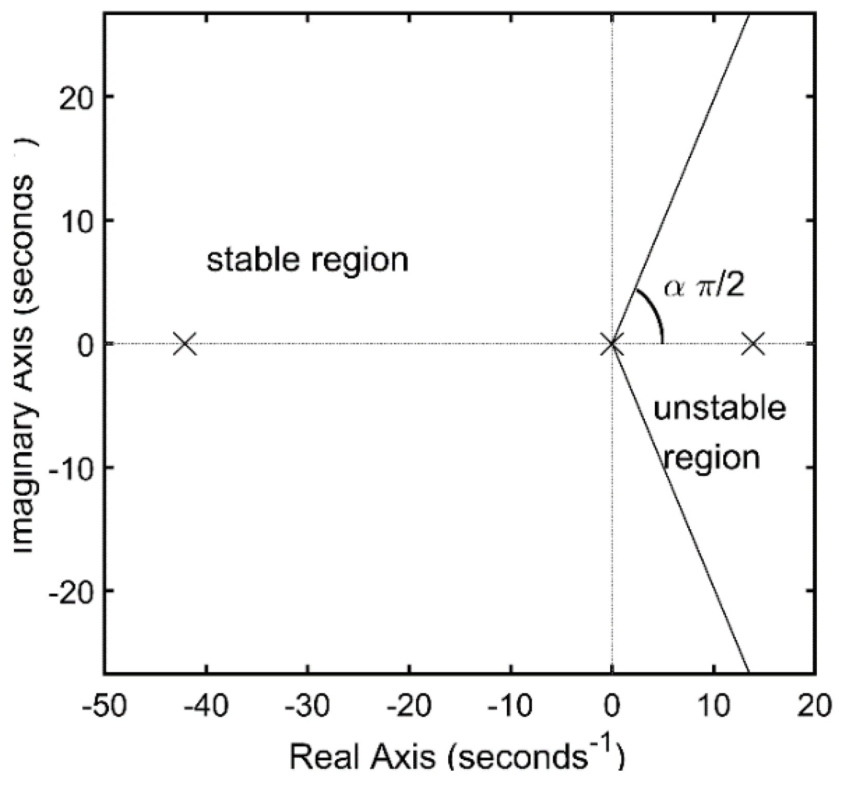
Note that the open-loop system with or without delay is unstable [2]. The free FOM is also unstable, where its unstableness is proven through Matignon’s theorem [25] that the eigenvalues of the FOM do not satisfy the condition represented as in Equation (30) and graphically illustrated in Figure 5:
| arg ( e i g ( A ) ) | > α π 2
The open-loop systems are highly unstable. However, even a state-feedback controller provided as in [4], the closed-loop system of the delay-free model with the controller as in Equation (31) still experiences the periodic motion as in Figure 3a.
δ c = 0.3 q 30 θ + 15 z ,       δ f = 0
The prior analysis of the delayed system [2] was also carried out using the same feedback controller. Therefore, the analysis of the proposed FOM uses the same controller to get the comparative results between the three models. The forward speed is set at V = 75 (m/s) for all the models. The fraction order in the FOM is chosen as α = 0.85 to make it equal to the advection delay τ = L/V = 0.02069 (s) in the delayed model. This selected fractional-order is called the typical order in this study. The initial condition is selected as trivial. The solution of the FOM is obtained by implementing the predictor-corrector method described in [26]. It can be observed from Figure 3 that the FOM and the delayed model have lower frequencies in the periodic motion than that of the delay-free model. The behavior of the FOM is similar to the delayed model except for some wriggles. The periodic motions are due to the corresponding tail-slaps in the planing forces shown in Figure 4, where there are similarities between the FOM and the delayed model, with lower-pace planing force compared to that of the delay-free model. The analysis shows that the FOM is able to describe the HSSV with memory effect by its fractional-order α instead of the advection delay term τ .
It is clear from Equation (27) that the proposed FOM includes a set of non-linear fractional-order differential equations so one can easily do the non-linear analysis such as finding the phase portrait and bifurcation diagram of the system with the nature of memory. The analysis of this FOM will be closer to the real HSSV with the advantage of changing the time-delay effect through the fractional-order α . For further analyses, the time delay is usually approximated by Pade’ approximation. This approximation may degrade the fidelity of the model. By using the fractional order to avoid the approximation, the proposed FOM can preserve the nature of the time delay.

3. Results and Discussion

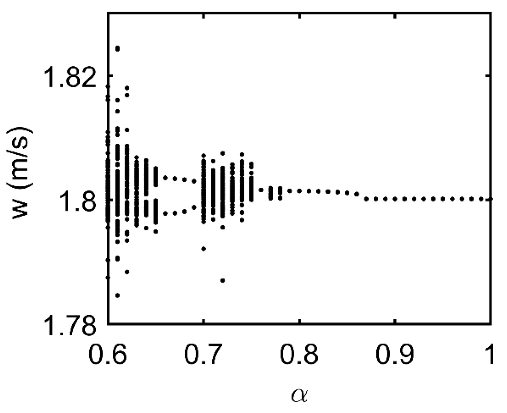
With lower fractional-order α , the FOM will be more dependent on delay, or in other words, the system has a longer memory. By choosing the forward speed V = 84.5 (m/s) to guarantee the stability for the FOM at high speed, the authors investigate the stability of the system with different fractional-order α in the available range [0.6; 1]. It is realized that with α closer to 1, the system is more stable. With smaller α , bifurcations will occur, as illustrated in Figure 6.
When reducing the fractional-order, a small chaotic motion starts to occur at α = 0.78, but disappears at α = 0.76 and reoccurs at α = 0.75 with bigger magnitudes. At α = 0.69, there is a sudden transformation from chaotic motion to a period-doubling bifurcation. At α = 0.65 the period-doubling bifurcation turns into two chaotic bands before merging into one large chaotic attractor at α = 0.64. This chaotic attractor is getting larger when α is further reduced.
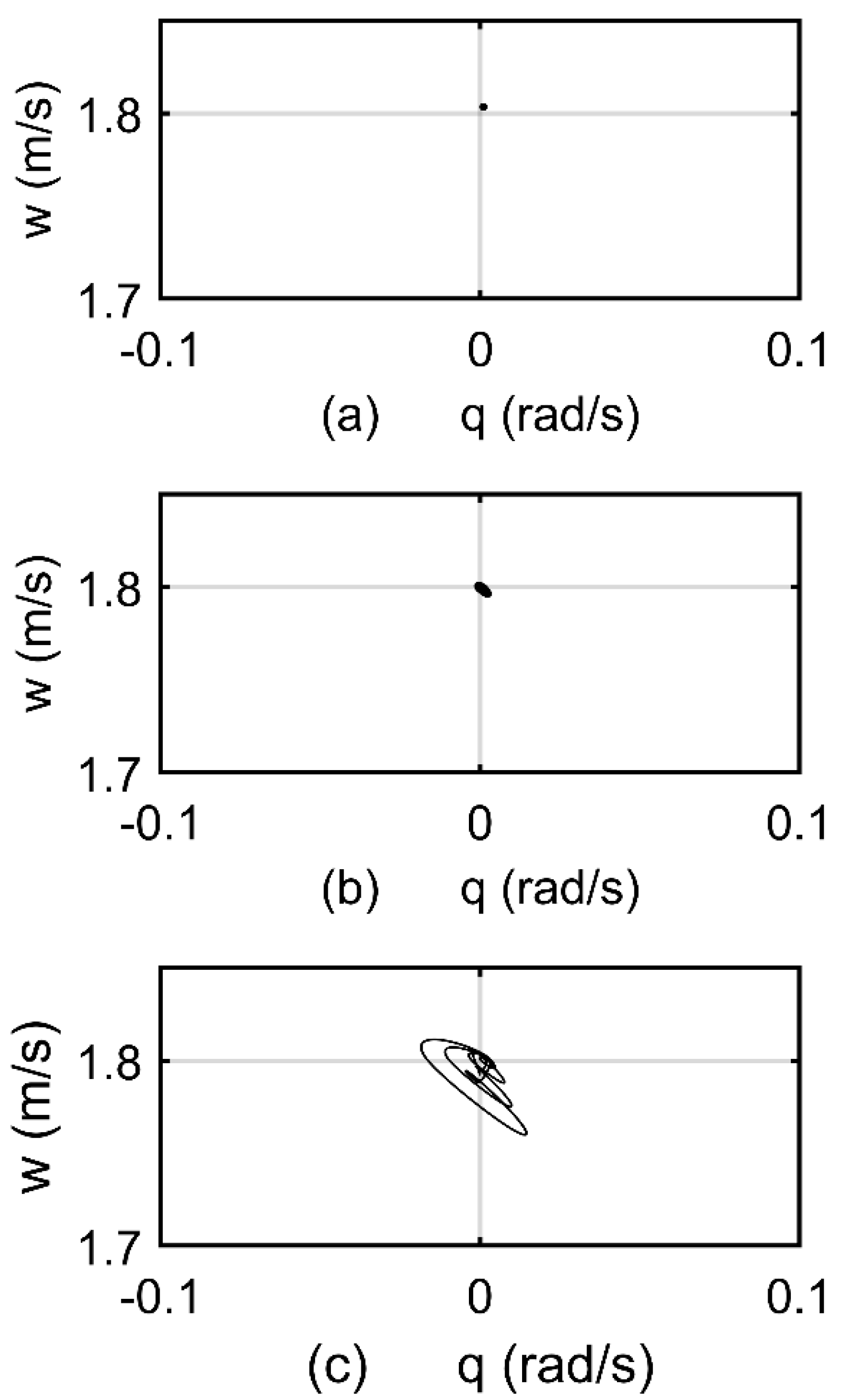
The effect of the fractional-order on the system stability is also illustrated through the phase portrait of two variables w and q around an equilibrium point (z*, w*, θ*, q*) = (0.04, 1.803, 0.02, 0.001). It can be observed from Figure 7a that at α = 0.85, the system is stable at the equilibrium point. When reducing the fractional order, the system remains in its stable state with all α > 0.78. At α = 0.78, a stable limit is born as in Figure 7b and the size of the limit cycle increases at α = 0.74 as in Figure 7c.
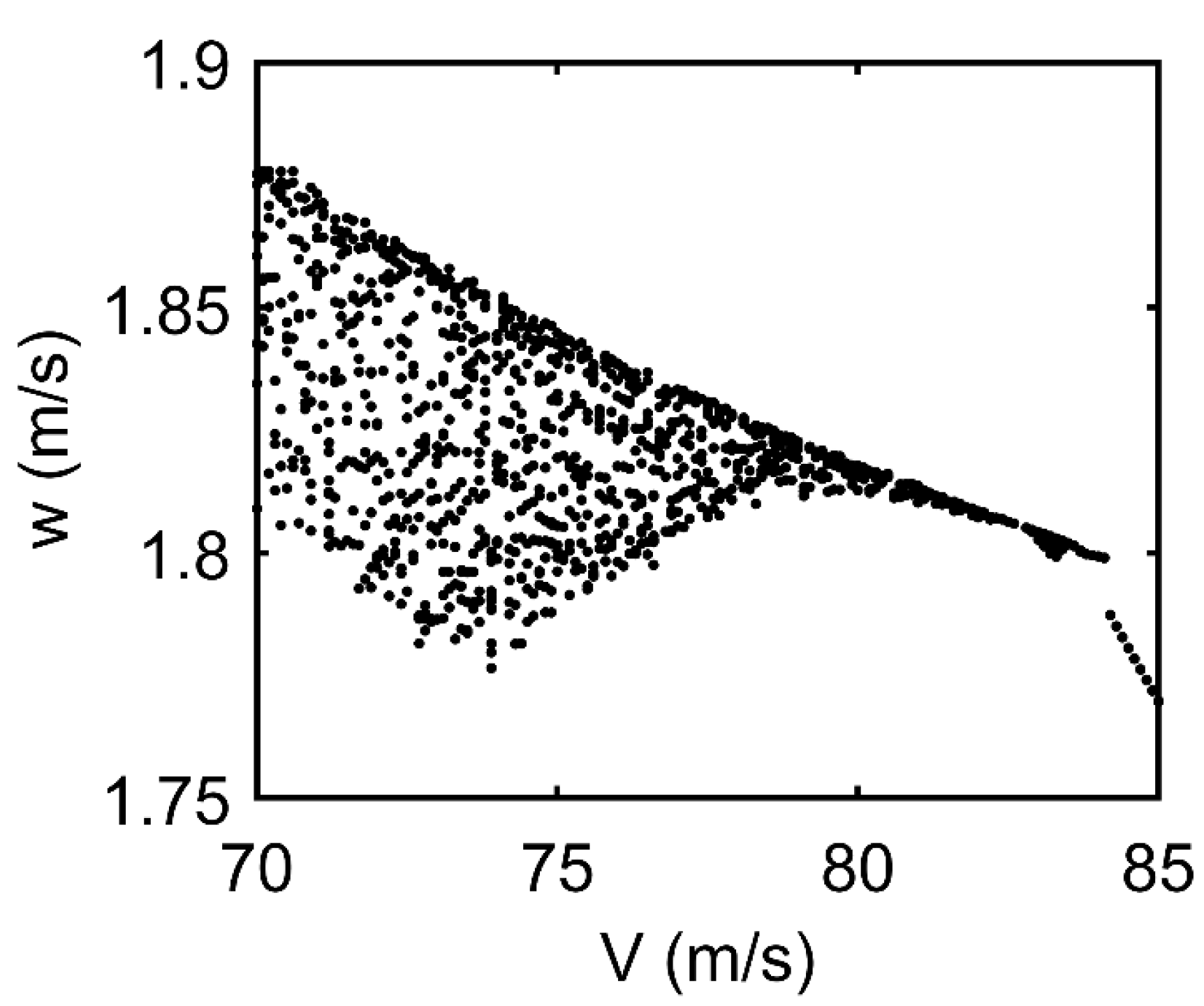
It worth noting that the forward speed also affects HSSV stability. The bifurcation diagram of the delay-free model respecting the forward speed V is shown in Figure 8. The figure agrees with the result in the literature that the delay-free model has periodic motions with V ≤ 83.4 (m/s) and moves smoother with stability at higher speeds [2]. It also shows that the size of the periodic motion is increasing quickly with V < 80 (m/s).
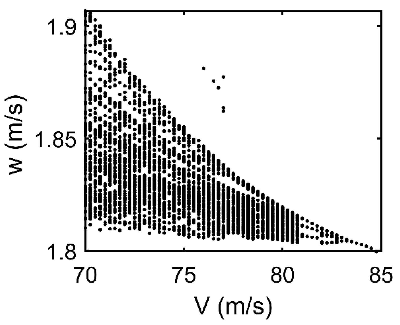
In this section, the bifurcation analysis with respect to the forward speed V of the FOM is also investigated. The simulation result will be compared with that of the delay-free model. The fractional-order of the FOM is selected at α = 0.85. The bifurcation diagram is illustrated in Figure 9. It can be observed from the figure that there is no bifurcation with V > 83.3 m/s. With V in the range [81; 83.3], there are period-doubling bifurcations that merge into a chaotic attractor starting from V < 81 m/s. This analysis suggests the HSSV travel at speeds faster than 83.3 m/s to be more stable.
Through the aforementioned analyses, one can realize that both fractional-order α and forward speed V have effects on the FOM stability. Therefore, a bifurcation study has been carried in 3D space, including the forward speed V, fractional-order α, and vertical speed w along the three axes x, y, and z, respectively. Let call α* the minimum fractional-orders before a bifurcation occurs. In Figure 10, it can be observed that with V ≤ 84 (m/s), there is no bifurcation with α > 0.92. It means α* = 0.92. When V = 84.1, α* suddenly jumps down to 0.82. With V > 84 (m/s), α* is almost inversely proportional to V. This analysis shows a general view of the behavior and stability of the FOHSSV. It is worth noting that the delay time is proportional to the length of the HSSV. Vehicles with different lengths have different delay times, corresponding to different fractional orders. Hence based on the study, one can have ideas for better designs of vehicle shapes and robust controllers for real HSSVs by choosing the areas with high stability.

4. Conclusions

In this paper, a new FOM has been introduced to describe the HSSV with memory effects. The FOM has the same behavior as the delayed model, which is closer to the real HSSV compared to many delay-free models that ignore delay effects. The fractional-order of the FOM plays the role of the time delay with lower fractional-orders equal to longer delay times. In this fractional-order form, the proposed model provides a better description of the HSSV with conveniences in the analysis of the non-linear model with no linearization. The time delay can be easily adjusted by changing the fractional-order. The numerical simulation validates the proposed model with similarities between the literature and the FOM. The bifurcation analyses provide a general view of system behavior at different levels of delay and velocity. This study suggests that more appropriate controllers for HSSVs should be designed based on the new proposed FOM. The next study will be about the robust fractional-order controller for this FOM.

Author Contributions

Conceptualization, P.T.D.; methodology, P.D.H.B.; software, H.L.N.N.T.; validation, S.H.; writing—review and editing, P.D.H.B.; visualization, M.T.V. All authors have read and agreed to the published version of the manuscript.

Funding

This research received no external funding.

Institutional Review Board Statement

Not applicable.

Informed Consent Statement

Not applicable.

Data Availability Statement

Data sharing is not applicable to this article.

Conflicts of Interest

The authors declare no conflict of interest.

Appendix A

a 22 = C V T m ( 1 n L ) S + 17 36 n L
a 24 = V T S ( C n m + 7 9 ) V T ( C n m + 17 36 ) 17 36 L 2
a 42 = C V T m ( 17 36 11 n 36 )
a 44 = 11 C V T n L 36 m
b 21 = C V 2 T n m ( S L + 17 L 36 ) , b 22 = C V 2 T S m L
b 41 = 11 C V 2 T n 36 m , b 42 = 17 C V 2 T 36 m
d 2 = T m ( 17 L 36 + S L ) , d 4 = 11 T 36 m
S = 0.18 R 2 + 0.328 L 2 , T = 1 0.7 S 0.2 L 2
C x = C x 0 ( 1 + σ ) , C = 0.5 C x R n 2 R 2
R c = R n 0.82 1 + σ σ K 2 , K 1 = L R n ( 1.92 σ 3 ) 1
K 2 = 1 ( 1 4.5 σ 1 + σ ) K 1 40 / 17
R ˙ c = 1.176 ( 0.82 1 + σ σ ) V ( 1 4.5 σ 1 + σ ) K 1 23 / 17 K 2 ( 1.92 σ 3 )

Appendix B

Table A1. Model parameters of the HSSV system.
ParameterValueUnit
Cx00.82Unitless
g9.81m/s2
L1.18m
m2Unitless
n0.5Unitless
Rn0.0191m
R0.0508m
V75m/s
σ 0.03Unitless

References

  1. Vanek, B.; Bokor, J.; Balas, G.J.; Arndt, R.E. Longitudinal motion control of a high-speed supercavitation vehicle. J. Vib. Control 2007, 13, 159–184. [Google Scholar] [CrossRef]
  2. Munther, A.H.; Nguyen, V.; Balachandran, B.; Abed, E.H. Stability analysis and control of supercavitating vehicles with advection delay. J. Comput. Nonlinear Dynam. 2013, 8, 021003. [Google Scholar] [CrossRef]
  3. Kirschner, I.; Rosenthal, B.J.; Uhlman, J. Simplified dynamical systems analysis of supercavitating high-speed bodies. In Proceedings of the Fifth International Symposium on Cavitation (CAV2003), Osaka, Japan, 1 November 2003. [Google Scholar]
  4. Dzielski, J.; Kurdila, A. A benchmark control problem for supercavitating vehicles and an initial investigation of solutions. J. Vib. Control 2003, 9, 791–804. [Google Scholar] [CrossRef]
  5. Han, Y.; Geng, R. Active disturbance rejection control of underwater high-speed vehicle. In Proceedings of the IEEE International Conference on Automation and Logistics, Zhengzhou, China, 15–17 August 2012. [Google Scholar]
  6. Ahn, S. An Integrated Approach to the Design of Supercavitating Underwater Vehicles. Ph.D. Thesis, Georgia Institute of Technology, Atlanta, GA, USA, 2007. [Google Scholar]
  7. Li, D.; Zhang, Y.; Luo, K.; Dang, J. Robust control of underwater supercavitating vehicles based on pole assignment. In Proceedings of the International Conference on Intelligent Human-Machine Systems and Cybernetics, Hangzhou, China, 26–27August 2009. [Google Scholar]
  8. Choi, J.; Ruzzene, M.; Bauchau, O.A. Dynamic analysis of flexible supercavitating vehicles using modal based elements. Simulation 2004, 80, 619–633. [Google Scholar] [CrossRef]
  9. Nguyen, V.; Balachandran, B. Supercavitating vehicles with noncylindrical, nonsymmetric cavities: Dynamics and instabilities. J. Comput. Nonlinear Dynam. 2011, 6, 041001. [Google Scholar] [CrossRef]
  10. Solteiro Pires, E.J.; Tenreiro Machado, J.A.; Moura Oliveira, P.B. Fractional order dynamics in a GA planner. Signal Process 2003, 83, 2377–2386. [Google Scholar] [CrossRef]
  11. Sheng, H.; Chen, Y.Q.; Qiu, T.S. Fractional Processes and Fractional-Order Signal Processing; Springer: New York, NY, USA, 2012. [Google Scholar]
  12. Ionescu, C.M. The Human Respiratory System an Analysis of the Interplay between Anatomy, Structure, Breathing and Fractal Dynamics; Springer: Berlin/Heidelberg, Germany, 2013. [Google Scholar]
  13. Yuste, S.B.; Acedo, L.; Lindenberg, K. Reaction front in an A + B → C reaction-subdiffusion process. Phys. Rev. E 2004, 69, 036126. [Google Scholar] [CrossRef] [PubMed] [Green Version]
  14. Lin, W. Global existence theory and chaos control of fractional differential equations. J. Math. Anal. Appl. 2007, 332, 709–726. [Google Scholar] [CrossRef] [Green Version]
  15. Lo, A.W. Long-term memory in stock market prices. Econometrica 1991, 59, 1279–1313. [Google Scholar] [CrossRef]
  16. Gabano, J.-D.; Poinot, T. Fractional modeling applied to nondestructive thermal characterization. In Proceedings of the 18th IFAC World Congress, Milano, Italy, 28 August–2 September 2011; pp. 13972–13977. [Google Scholar]
  17. Hartley, T.T.; Lorenzo, C.F.; Qammar, H.K. Chaos in a fractional order chua system. IEEE Trans. Circuits Syst. I 1995, 42, 485–490. [Google Scholar] [CrossRef]
  18. Chen, W.C. Nonlinear dynamics and chaos in a fractional-order financial system. Chaos Solitons Fractals 2008, 36, 1305–1314. [Google Scholar] [CrossRef]
  19. Fathalla, A.R. Numerical modeling of fractional-order biological systems. Abstr. Appl. Anal. 2013, 2013, 816803. [Google Scholar]
  20. Oustaloup, A.; Levron, F.; Mathieu, B.; Nanot, F.M. Frequency band complex noninteger differentiator: Characterization and synthesis. IEEE Trans. Circuit Syst. I Fundam. Theory Appl. 2000, 47, 25–39. [Google Scholar] [CrossRef]
  21. Logvinovich, G. Hydrodynamics of Free-Boundary Flows; Russian (NASA-TT-F-658), Translator; US Department of Commerce: Washington, DC, USA, 1972.
  22. Liberzon, D. Switching in Systems and Control; Birkhauser: Cambridge, MA, USA, 2003; pp. 3–9. [Google Scholar]
  23. Lin, G.; Balachandran, B.; Abed, E.H. Nonlinear dynamics and bifurcations of a supercavitating vehicle. IEEE J. Ocean. Eng. 2007, 32, 753–761. [Google Scholar] [CrossRef]
  24. Lin, G.; Balachandran, B.; Abed, E.H. Supercavitating body dynamics, bifurcations and control. In Proceedings of the American Control Conference, Portland, OR, USA, 8–10 June 2005. [Google Scholar] [CrossRef]
  25. Matignon, D. Generalized fractional differential and difference equations: Stability properties and modelling issues. In Proceedings of the Mathematical Theory of Networks and Systems Symposium, Padova, Italy, 6–10 July 1998. [Google Scholar]
  26. Diethelm, K.; Freed, A.D. The Frac PECE subroutine for the numerical solution of differential equations of fractional-order. In Forschung und Wissenschaftliches Rechnen; Heinzel, S., Plesser, T., Eds.; Gessellschaft fur Wissenschaftliche Datenverarbeitung: Gottingen, Germany, 1999; pp. 57–71. [Google Scholar]
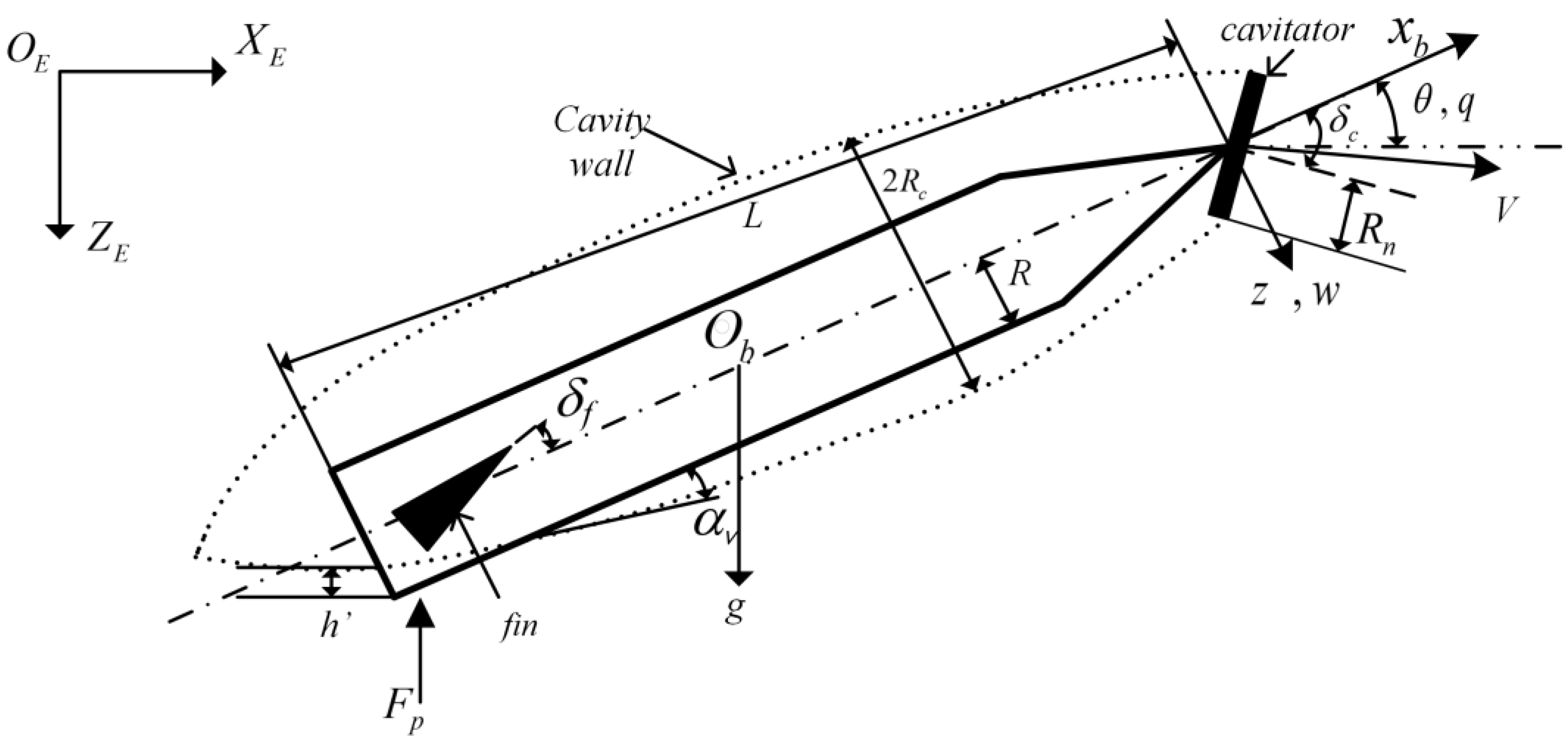
Figure 1. The configuration diagram of an HSSV.
Machines 09 00129 g001
Figure 2. Non-linear planing force.
Machines 09 00129 g002
Figure 3. Closed-loop system response for delay dependent system with trivial initial condition and δ c = 0.3 q 30 θ + 15 z ,       δ f = 0 . (a,d) delay-free model and corresponding control signal; (b,e) delayed model and corresponding control signal; (c,f) FOM and corresponding control signal.
Machines 09 00129 g003
Figure 4. Planing forces in three models being respective to the time responses in Figure 3: (a) delay-free model; (b) delayed model; (c) FOM.
Machines 09 00129 g004
Figure 5. Stability region of the FOM with α = 0.85.
Machines 09 00129 g005
Figure 6. Bifurcation diagram of the FOM respecting to fractional-order α (V = 84.5).
Machines 09 00129 g006
Figure 7. Effect of fractional-order on system stability: (a) α = 0.85; (b) α = 0.78; (c) α = 0.74.
Machines 09 00129 g007
Figure 8. Bifurcation diagram of the delay-free model respecting to forward speed V.
Machines 09 00129 g008
Figure 9. Bifurcation diagram of the FOM respecting to forward speed V (α = 0.85).
Machines 09 00129 g009
Figure 10. 3D bifurcation diagram of the FOM respecting to both α and V.
Machines 09 00129 g010
Publisher’s Note: MDPI stays neutral with regard to jurisdictional claims in published maps and institutional affiliations.