
Dimensional (Parametric) Synthesis of the Hexapod-Type Parallel Mechanism with Reconfigurable Design


Abstract
1. Introduction
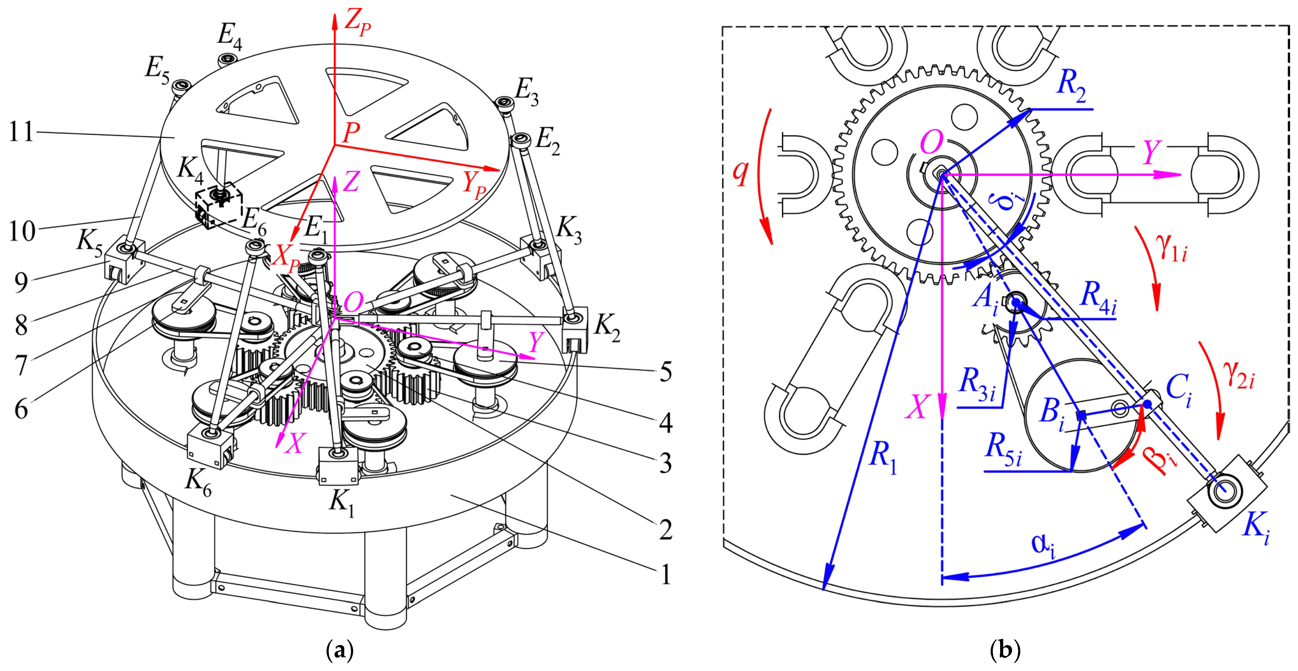
2. Mechanism Design
- a single drive that stays fixed in the center of the base;
- correctly chosen cranks’ lengths allow for the elimination of the possibility of collision between the adjacent carriages (unlike other types of mechanisms with circular guides);
- reconfigurability, which allows the platform to have diverse trajectories while having a single actuation.
3. Configuration Analysis
4. Dimensional Synthesis Algorithm
- Since the mechanism has only one degree of freedom, we cannot set all six components of vector X independently. Only one coordinate can be defined explicitly.
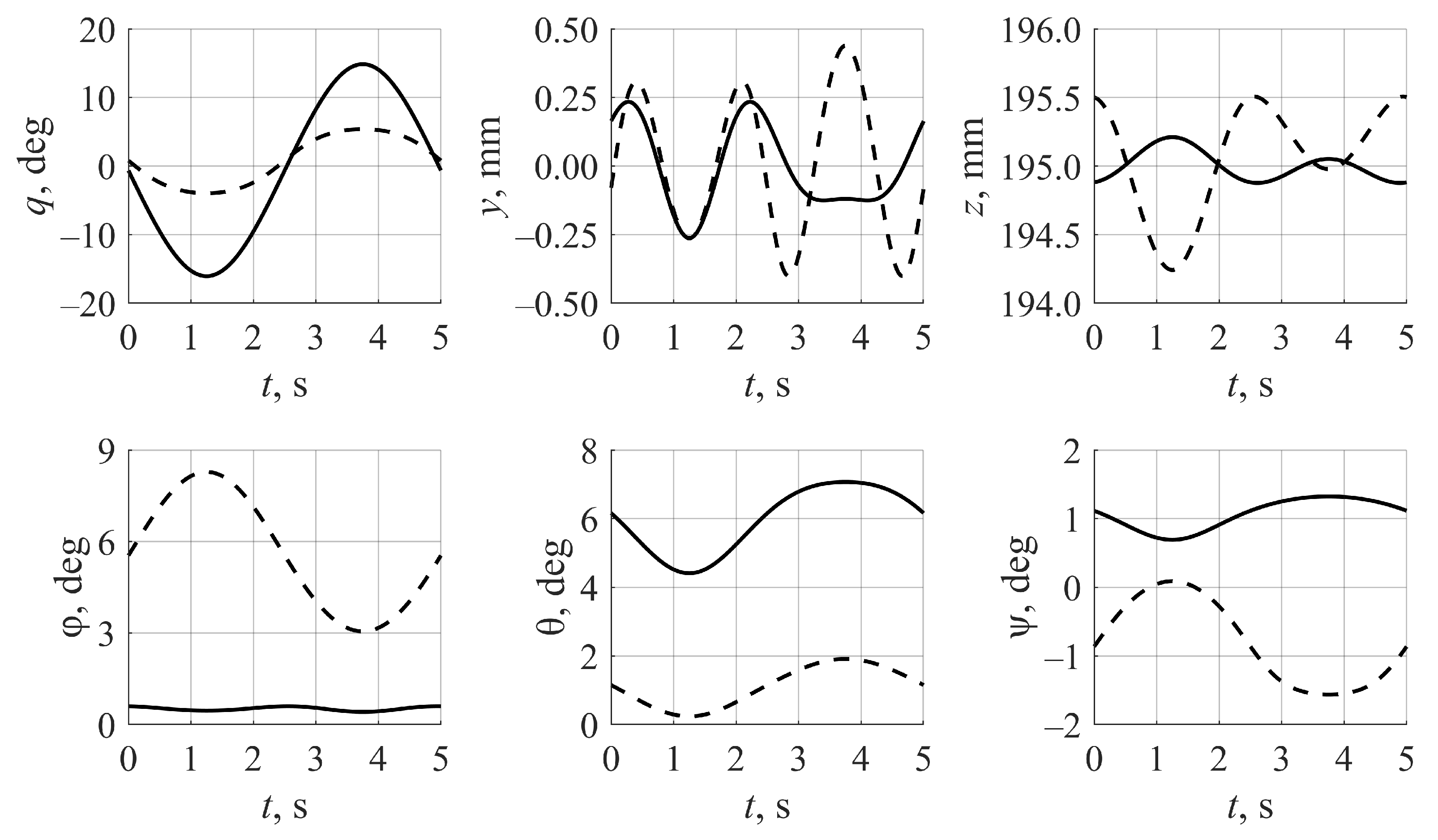
5. Examples of Dimensional Synthesis
6. Computational Accuracy and Comparison with Other Works
7. Conclusions
Author Contributions
Funding
Institutional Review Board Statement
Informed Consent Statement
Data Availability Statement
Conflicts of Interest
References
- Merlet, J.-P. Parallel Robots, 2nd ed.; Springer: Dordrecht, The Netherlands, 2006. [Google Scholar] [CrossRef]
- Glazunov, V.A.; Chunichin, A.Y. Development of mechanisms of parallel structure. J. Mach. Manuf. Reliab. 2014, 43, 211–216. [Google Scholar] [CrossRef]
- Rosyid, A.; El-Khasawneh, B.; Alazzam, A. Review article: Performance measures of parallel kinematics manipulators. Mech. Sci. 2020, 11, 49–73. [Google Scholar] [CrossRef]
- Russo, M.; Raimondi, L.; Dong, X.; Axinte, D.; Kell, J. Task-oriented optimal dimensional synthesis of robotic manipulators with limited mobility. Robot. Comput. Manuf. 2021, 69, 102096. [Google Scholar] [CrossRef]
- Huang, T.; Li, Z.; Li, M.; Chetwynd, D.G.; Gosselin, C.M. Conceptual design and dimensional synthesis of a novel 2-DOF translational parallel robot for pick-and-place operations. J. Mech. Des. 2004, 126, 449–455. [Google Scholar] [CrossRef]
- Dastjerdi, A.H.; Sheikhi, M.M.; Masouleh, M.T. A complete analytical solution for the dimensional synthesis of 3-DOF delta parallel robot for a prescribed workspace. Mech. Mach. Theory 2020, 153, 103991. [Google Scholar] [CrossRef]
- Li, J.; Ye, F.; Shen, N.; Wang, Z.; Geng, L. Dimensional synthesis of a 5-DOF hybrid robot. Mech. Mach. Theory 2020, 150, 103865. [Google Scholar] [CrossRef]
- Liu, X.-J.; Jin, Z.-L.; Gao, F. Optimum design of 3-DOF spherical parallel manipulators with respect to the conditioning and stiffness indices. Mech. Mach. Theory 2000, 35, 1257–1267. [Google Scholar] [CrossRef]
- Gosselin, C.; Angeles, J. A global performance index for the kinematic optimization of robotic manipulators. J. Mech. Des. 1991, 113, 220–226. [Google Scholar] [CrossRef]
- Xu, L.; Chen, Q.; He, L.; Li, Q. Kinematic analysis and design of a novel 3T1R 2-(PRR)2RH hybrid manipulator. Mech. Mach. Theory 2017, 112, 105–122. [Google Scholar] [CrossRef]
- Altuzarra, O.; Hernandez, A.; Salgado, O.; Angeles, J. Multiobjective optimum design of a symmetric parallel Schönflies-motion generator. Trans. ASME J. Mech. Des. 2009, 131, 031002. [Google Scholar] [CrossRef]
- Li, Z.; Lou, Y.; Zhang, Y.; Liao, B.; Li, Z. Type synthesis, kinematic analysis, and optimal design of a novel class of Schönflies-motion parallel manipulators. IEEE Trans. Autom. Sci. Eng. 2013, 10, 674–686. [Google Scholar] [CrossRef]
- Urizar, M.; Petuya, V.; Diez, M.; Hernandez, A. Non-singular transitions based design methodology for parallel manipulators. Mech. Mach. Theory 2015, 91, 168–186. [Google Scholar] [CrossRef]
- Wan, X.J.; Li, Q.L. Dimensional synthesis of a robotized cell of support fixture. Robot. Comput. Manuf. 2017, 48, 80–92. [Google Scholar] [CrossRef]
- Cardou, P.; Bouchard, S.; Gosselin, C. Kinematic sensitivity indices for dimensionally nonhomogeneous Jacobian matrices. IEEE Trans. Robot. 2010, 26, 166–173. [Google Scholar] [CrossRef]
- Chablat, D.C.; Wenger, P.; Merlet, J.-P. A Comparative study between two three-DOF parallel kinematic machines using kinetostatic criteria and interval analysis. In Proceedings of the 11th World Congress in Mechanism and Machine Science, Tianjin, China, 1–4 April 2004; pp. 1–6. [Google Scholar]
- Liu, G.; Chen, Y.; Xie, Z.; Geng, X. GA\SQP optimization for the dimensional synthesis of a delta mechanism based haptic device design. Robot. Comput. Manuf. 2018, 51, 73–84. [Google Scholar] [CrossRef]
- Hamida, I.B.; Laribi, M.A.; Mlika, A.; Romdhane, L.; Zeghloul, S. Dimensional synthesis and performance evaluation of four translational parallel manipulators. Robotica 2020, 39. [Google Scholar] [CrossRef]
- Kelaiaia, R.; Zaatri, A.; Company, O.; Chikh, L. Some investigations into the optimal dimensional synthesis of parallel robots. Int. J. Adv. Manuf. Technol. 2016, 83, 1525–1538. [Google Scholar] [CrossRef]
- Hamida, I.B.; Laribi, M.A.; Mlika, A.; Romdhane, L.; Zeghloul, S.; Carbone, G. Multi-objective optimal design of a cable driven parallel robot for rehabilitation tasks. Mech. Mach. Theory 2021, 156, 104141. [Google Scholar] [CrossRef]
- Merlet, J.-P.; Daney, D. Dimensional synthesis of parallel robots with a guaranteed given accuracy over a specific workspace. In Proceedings of the 2005 IEEE International Conference on Robotics and Automation, Barcelona, Spain, 18–22 April 2005; pp. 942–947. [Google Scholar] [CrossRef]
- Sun, T.; Song, Y.; Li, Y.; Liu, L. Dimensional synthesis of a 3-DOF parallel manipulator based on dimensionally homogeneous Jacobian matrix. Sci. China Ser. E-Technol. Sci. 2010, 53, 168–174. [Google Scholar] [CrossRef]
- Carbone, G.; Ottaviano, E.; Ceccarelli, M. An optimum design procedure for both serial and parallel manipulators. Proc. Inst. Mech. Eng. Part. C J. Mech. Eng. Sci. 2007, 221, 829–843. [Google Scholar] [CrossRef]
- Affi, Z.; Romdhane, L.; Maalej, A. Dimensional synthesis of a 3-translational-DOF in-parallel manipulator for a desired workspace. Eur. J. Mech. A Solids 2004, 23, 311–324. [Google Scholar] [CrossRef]
- Borras, J.; Thomas, F.; Ottaviano, E.; Ceccarelli, M. A reconfigurable 5-DoF 5-SPU parallel platform. In Proceedings of the ASME/IFToMM International Conference on Reconfigurable Mechanisms and Robots, London, UK, 22–24 June 2009; pp. 617–623. [Google Scholar]
- Kuo, C.-H.; Dai, J.S.; Yan, H.-S. Reconfiguration principles and strategies for reconfigurable mechanisms. In Proceedings of the ASME/IFToMM International Conference on Reconfigurable Mechanisms and Robots, London, UK, 22–24 June 2009; pp. 1–7. [Google Scholar]
- Wu, G.; Dong, H.; Wang, D.; Bai, S. A 3-RRR spherical parallel manipulator reconfigured with four-bar linkages. In Proceedings of the International Conference on Reconfigurable Mechanisms and Robots (ReMAR), Delft, The Netherlands, 20–22 June 2018; pp. 1–7. [Google Scholar] [CrossRef]
- Kong, X.; Gosselin, C.M.; Richard, P. Type synthesis of parallel mechanisms with multiple operation modes. J. Mech. Des. 2007, 129, 595–601. [Google Scholar] [CrossRef]
- Karimi, A.; Masouleh, M.-T.; Cardou, P. Avoiding the singularities of 3-RPR parallel mechanisms via dimensional synthesis and self-reconfigurability. Mech. Mach. Theory 2016, 99, 189–206. [Google Scholar] [CrossRef]
- Sarabandi, S.; Grosch, P.; Porta, J.M.; Thomas, F. A reconfigurable asymmetric 3-UPU parallel robot. In Proceedings of the International Conference on Reconfigurable Mechanisms and Robots (ReMAR), Delft, The Netherlands, 20–22 June 2018; pp. 1–8. [Google Scholar] [CrossRef]
- Zhang, M.; Cao, J.; Zhu, G.; Miao, Q.; Zeng, X.; Xie, S.Q. Reconfigurable workspace and torque capacity of a compliant ankle rehabilitation robot (CARR). Robot. Auton. Syst. 2017, 98, 213–221. [Google Scholar] [CrossRef]
- Herrero, S.; Mannheim, T.; Prause, I.; Pinto, C.; Corves, B.; Altuzarra, O. Enhancing the useful workspace of a reconfigurable parallel manipulator by grasp point optimization. Robot. Comput. Manuf. 2015, 31, 51–60. [Google Scholar] [CrossRef]
- Huang, G.; Guo, S.; Zhang, D.; Qu, H.; Tang, H. Kinematic analysis and multi-objective optimization of a new reconfigurable parallel mechanism with high stiffness. Robotica 2018, 36, 187–203. [Google Scholar] [CrossRef]
- Carbonari, L.; Callegari, M.; Palmieri, G.; Palpacelli, M.-C. A new class of reconfigurable parallel kinematic machines. Mech. Mach. Theory 2014, 79, 173–183. [Google Scholar] [CrossRef]
- Bi, Z.; Wang, L. Optimal design of reconfigurable parallel machining systems. Robot. Comput. Manuf. 2009, 25, 951–961. [Google Scholar] [CrossRef]
- Ye, W.; Chai, X.; Zhang, K. Kinematic modeling and optimization of a new reconfigurable parallel mechanism. Mech. Mach. Theory 2020, 149, 103850. [Google Scholar] [CrossRef]
- Huang, G.; Zhang, D.; Guo, S.; Qu, H. Design and optimization of a novel three-dimensional force sensor with parallel structure. Sensors 2018, 18, 2416. [Google Scholar] [CrossRef]
- Fomin, A.; Antonov, A.; Glazunov, V. Forward kinematic analysis of a rotary hexapod. In ROMANSY 23-Robot Design, Dynamics and Control. ROMANSY 2020; Venture, G., Solis, J., Takeda, Y., Konno, A., Eds.; CISM International Centre for Mechanical Sciences (Courses and Lectures); Springer: Cham, Switzerland, 2021; Volume 601, pp. 486–494. [Google Scholar] [CrossRef]
- Bohigas, O.; Manubens, O.; Ros, L. Singularities of Robot Mechanisms; Springer: Cham, Switzerland, 2017. [Google Scholar] [CrossRef]
- Bhattacharya, S.; Hatwal, H.; Ghosh, A. On the optimum design of Stewart platform type parallel manipulators. Robotica 1995, 13, 133–140. [Google Scholar] [CrossRef]
- Merlet, J.-P. Optimal design for the micro parallel robot MIPS. In Proceedings of the 2001 IEEE International Conference on Robotics and Automation (ICRA), Washington, DC, USA, 11–15 May 2002; pp. 1149–1154. [Google Scholar] [CrossRef]
- Hao, F.; Merlet, J.-P. Multi-criteria optimal design of parallel manipulators based on interval analysis. Mech. Mach. Theory 2005, 40, 157–171. [Google Scholar] [CrossRef]
- Miller, K. Optimal design and modeling of spatial parallel manipulators. Int. J. Robot. Res. 2004, 23, 127–140. [Google Scholar] [CrossRef]
- Rao, A.B.K.; Rao, P.V.M.; Saha, S.K. Dimensional design of hexaslides for optimal workspace and dexterity. IEEE Trans. Robot. 2005, 21, 444–449. [Google Scholar] [CrossRef]
- Unal, R.; Kizitas, G.; Patoglu, V. A multi-criteria design optimization framework for haptic interfaces. In Proceedings of the 2008 Symposium on Haptic Interfaces for Virtual Environment and Teleoperator Systems, Reno, NV, USA, 13–14 March 2008; pp. 231–238. [Google Scholar] [CrossRef]
- Jiang, Q.; Gosselin, C.M. Geometric optimization of the MSSM Gough–Stewart platform. J. Mech. Robot. 2009, 1, 031006. [Google Scholar] [CrossRef]
- Parivash, F.; Ghasemi, A. Optimum dimensional synthesis of the Gough parallel manipulator for a desired workspace. In Proceedings of the 2017 IEEE 4th International Conference on Knowledge-Based Engineering and Innovation (KBEI), Tehran, Iran, 22 December 2017; pp. 559–564. [Google Scholar] [CrossRef]
- Muralidharan, V.; Bose, A.; Chatra, K.; Bandyopadhyay, S. Methods for dimensional design of parallel manipulators for optimal dynamic performance over a given safe working zone. Mech. Mach. Theory 2020, 147, 103721. [Google Scholar] [CrossRef]


Publisher’s Note: MDPI stays neutral with regard to jurisdictional claims in published maps and institutional affiliations. |
© 2021 by the authors. Licensee MDPI, Basel, Switzerland. This article is an open access article distributed under the terms and conditions of the Creative Commons Attribution (CC BY) license (https://creativecommons.org/licenses/by/4.0/).
Share and Cite
Fomin, A.; Antonov, A.; Glazunov, V.; Carbone, G. Dimensional (Parametric) Synthesis of the Hexapod-Type Parallel Mechanism with Reconfigurable Design. Machines 2021, 9, 117. https://doi.org/10.3390/machines9060117
Fomin A, Antonov A, Glazunov V, Carbone G. Dimensional (Parametric) Synthesis of the Hexapod-Type Parallel Mechanism with Reconfigurable Design. Machines. 2021; 9(6):117. https://doi.org/10.3390/machines9060117
Chicago/Turabian StyleFomin, Alexey, Anton Antonov, Victor Glazunov, and Giuseppe Carbone. 2021. "Dimensional (Parametric) Synthesis of the Hexapod-Type Parallel Mechanism with Reconfigurable Design" Machines 9, no. 6: 117. https://doi.org/10.3390/machines9060117
APA StyleFomin, A., Antonov, A., Glazunov, V., & Carbone, G. (2021). Dimensional (Parametric) Synthesis of the Hexapod-Type Parallel Mechanism with Reconfigurable Design. Machines, 9(6), 117. https://doi.org/10.3390/machines9060117