1. Introduction
This paper is an extension of work originally presented in “International Russian Automation Conference (RusAutoCon), Sochi, Russia, 2020” [
1].
An urgent problem of mankind is the effective provision of food to populations, taking into account population growth rates. One of the possible solutions to this problem is the use of greenhouse complexes that allow year-round plant food production. Modern greenhouse complexes have significant automation, which enables an increase in productivity. However, a large number of greenhouse farms still use the greenhouses of older generations that do not provide for complex automation of technological processes. As a rule, in such farms, automation systems are created for each of the subsystems of the microclimate system. The heat supply system is the main subsystem necessary for the functioning of the greenhouse complex year-round. There are various solutions for heat supply systems automation [
2,
3,
4,
5,
6,
7].
The purpose of the study is the possibility of geothermal heat supply system automation. Scale (salt deposit) is formed on electrically driven valves after a short period of operation (about 14 days). Thus, valves jam and the electric motors cannot operate mechanically due to the resulting scale. They do not allow regulating the volume of geothermal water. Reagent methods are used to ensure greater efficiency of the heat supply system. However, it only slows down the scale formation process inside the heat exchange equipment (1–2 months) and does not solve the main problem—the formation of scale on the elements of heating equipment for a long time operation.
In accordance with the purpose of the research, experiences with geothermal sources in different countries and surveys related to this issue were studied.
A group of authors from Arizona [
8] notes that greenhouses play a significant role in modern agriculture, despite a large energy input required for heating systems. The way out of this situation, according to the authors of the article, is the use of geothermal power engineering. The authors of the study analyzed the suitability of geothermal heat sources for agricultural needs based on the University of Bari experimental farm by measuring experimental data (greenhouse temperature and heat pump performance). Experimental results from this research confirm that geothermal heat sources are efficient, economical and environmentally friendly and can be useful for meeting the thermal energy demand of greenhouses.
The authors of the paper [
9] conducted research in remote regions of Canada with a complex environment to provide traditional methods of reliable energy supply; they propose geothermal energy as a way out of the prevailing conditions and also note the positive aspects of renewable energy sources transition for the ecological situation. They highlight the benefits of geothermal energy use in Canada, focusing in particular on food security and assessing the technical and economic feasibility of producing vegetables using geothermal heat sources to meet energy needs. A geothermal heat supply system is utilized with the efficient use of nutrients, water and heat to produce a varied vegetable yield. The paper demonstrates the technical and economic feasibility of producing vegetables in a cold northern climate using geothermal energy systems despite high capital costs.
Hristov, Stoyanov and Valtchev [
10] note that Bulgaria is relatively rich in geothermal water with different temperature ranges. The highest temperature (about 100 °C) is measured at the surface; the total dissolved solids (TDS) ranges from 0.1 g/L to 150 g/L for most tanks. The installed capacity is about 97.5 MW (in 2017), excluding the use of low-grade energy by ground-based heat pumps. Geothermal energy has only direct use—in balneology, heating of buildings, air conditioning, greenhouses, ground-based geothermal heat pumps, direct thermal water supply to industrial processes. Geothermal water is also used for bottling drinking water and soft drinks. Most hydrothermal sites are developed as mountain or sea resorts. Electricity production from geothermal water is currently not available in the country.
The authors [
11] note that the geographic location of Turkey in the Mediterranean sector of the Alpine-Himalayan tectonic belt makes the country rich in geothermal resources. However, the share of the used potential is only about 2–3%. The research evaluates the possibilities of using geothermal heat supply in Turkey. The first application of geothermal heating was applied in 1981 to the Izmir-Balkova thermal facilities, while the first urban geothermal district heating system has been in operation in Balikesir-Gonen since 1987. Geothermal heat pumps have been introduced to the Turkish market since 1998, but there are still no Turkish manufacturers of this equipment. The author of the article, Hepbasli, sums up: geothermal energy will play a significant and growing role in Turkey’s energy strategy in the future [
11].
Boren [
12] reports that geothermal fluids have been used to heat greenhouses near Susanville, California, since 1979. Cucumbers and tomatoes are grown in a hydroponic system that does not require a rooting medium such as soil or gravel. High-quality groundwater is used for irrigation, and a shallow geothermal well provides heat exchange heaters with hot water. Thermostats and humidifiers control the greenhouse environment. The nutrients enter the irrigation water circulating through polyethylene pipes. However, this technology has not become competitive in the Los Angeles market.
The author of the article [
13] Toth notes that the main part of the geothermal potential of Hungary is used for resorts, while there is no developed market for ground-based heat pumps in the country, and the main projects are focused on geothermal power plants for district heating. The article describes the history of the Hungarian heat supply and also notes that for the direct use of heat, agriculture was the main sector; about 75% of the capacity was used for heating greenhouses and plastic tents, 25% for animal husbandry.
A group of authors [
14] analyzed the use of renewable sources. According to their research, geothermal heat supply ranks second among renewable energy sources worldwide in terms of installed capacity (70.3 GW) and the amount of heat generated (163 TW h/year). It is second only to solar heat supply (480 GW and 395 TW h/year). Systems are described that use highly mineralized geothermal liquid from various geological horizons as heat transfer liquid with fresh water heating and circulation systems with silent circulation of the heat transfer liquid. The article provides examples of geothermal circulation systems, formulates main scientific and technical problems that require further research and development to build efficient and competitive geothermal heat supply systems in various regions of the country.
A group of authors [
15] describes in the article the state of geothermal energy in the Kamchatka Territory of Russia. The cost of electricity generated by geothermal power plants is two times less. Sixteen geothermal deposits have been explored on the peninsula, of which nine are being exploited. The designs and technological schemes of ten geothermal systems are described. Scenarios for the development of geothermal energy are described.
The authors [
16] discuss a study of geothermal energy in the Krasnodar Territory. The region provides only about 10% of its energy needs from its own resources. Economic and resort development, as well as environmental restrictions, stimulate the use of renewable energy sources. Single-circuit open heating systems are used without reinjection usually.
Hence, the current state of the energy sector sets the task of finding new energy sources and opens up prospects for a new stage of technical development.
Otto P. [
2] considers a model of automation of a large block greenhouse with two main subsystems: external climate and heating. The microprocessor technology is the base of these subsystems’ control. A system of air temperature automatic control of a greenhouse with the joint use of Smith extrapolator was developed by Tokmakova [
3]. It compensates for the transport delay in the system. Nicolosi G., Volpe R., Messineo A. [
7] considered the adaptive microclimate control system of a greenhouse. This control system uses a neural network to predict climatic changes in a greenhouse. This approach allows a response to internal and external climatic conditions changes in time, thereby increasing the overall regulation quality of the necessary parameters. It should be noted that some authors do not take into account the scale formation process as a characteristic of the heat supply systems operation. The scale formation process is the most acute problem when geothermal heat supply is used as an energy source.
Geothermal sources are used as sources of water supply for industrial and heating boiler houses of the agro-industrial complex, the use of which is widespread in the south of Russia. Since the mid-1960s, geothermal energy has become one of the means of using the Earth’s interior. In various regions, exploration expeditions were set up to drill and reconstruct oil and gas wells of thermal waters. The energy from geothermal resources may be greater than the potential of fossil fuels. The use of geothermal energy can account for a tenth of the total heat supply balance. In some regions, geothermal energy sources can account for up to 50–95% of the total energy consumption.
However, thermal carbonic water, as a rule, is saturated with calcium carbonate and other salts, and when it comes to the surface, the saturated solution precipitates. Crystalline salt deposits in pipes and on the surfaces of geothermal equipment are a serious problem in the use of such an attractive energy source. Deposits in pipes at the first stages have an island character, and then they form a continuous ring of sediments, on which stage layering is carried out. As a result of this, the hydraulic resistance of the pipelines increases, ending with their complete blockage and failure of the system [
17].
Localization of calcium carbonate deposition in systems using water from geothermal deposits is observed along the water transportation route. This localization, all other things being equal, depends on the values of pressure and temperature (different for the waters of different fields), but most often behind the valves, in places of a sharp drop in pressure.
The corrosive effect of geothermal waters on metal is caused by many factors: salinity, gas content (hydrogen sulfide, carbon dioxide, oxygen), pressure, temperature (the highest corrosion rate is observed at a temperature of 60–90 °C), pH value, etc. Oxygen is the most aggressive component in geothermal water. Oxygen is not contained in geothermal waters; it can enter through leaks in the system, while the intensity of oxygen saturation of thermal waters depends on their temperature and mineralization. Therefore, the hermetic element connection in the heat supply systems must be carefully ensured, which can be achieved by using welded joints and minimizing threaded joints and fittings. During periods of conservation of the heat supply system, in order to avoid air leaks, all communications and equipment contacting with the geothermal heat carrier must be filled with fresh water. Hydrogen sulfide increases the corrosion rate up to 40%, the maximum value of the corrosion rate is reached when its concentration is 4–5 mg/L [
18].
Corrosion caused by carbon dioxide is minimal compared to oxygen and hydrogen sulfide. Chlorine ions in combination with hydrogen sulfide and carbon dioxide have a corrosive effect on the metal. When oxygen enters the thermal water, hydrogen sulfide corrosion is intensified by 2 times, carbon dioxide by 1.5 times, and chlorine-ions by 3–4 times. Some thermal waters contain sulfate-reducing bacteria, which, when released into heating systems, can accelerate corrosion by a factor of 10–15.
The scale is formed on the inner walls of heat-exchange equipment with prolonged use. It adversely affects the heat transfer process [
19,
20]. This process is most intense if the water used as a heat carrier contains large amounts of mineral salts. The process of scale formation on the internal surfaces of the heat exchange equipment causes deterioration of the process control quality due to scale, which impedes the operation of control devices; for example, various mixing valves and ball valves, which supply the heat carrier to the main circuit of the heating system.
Greenhouse temperatures and humidity monitoring is a major problem of agricultural practice. This fact is due to a sharp daily change in climatic conditions and its potentially detrimental effect on plant growth. A greenhouse is a complex thermodynamic system in which temperature and relative humidity should be carefully controlled to optimize plant growth.
There are a large number of different ready-made solutions for the organization of microclimate systems in greenhouses currently. Modern greenhouse climate systems include many different adjustable parameters: air temperature, soil temperature, humidity, light, carbon dioxide level and other, parameters [
7]. The main disadvantage of such systems is their high cost and the difficulty of introduction into the existing greenhouses of past generations.
For greenhouses that are equipped with an air-convection heating system using a geothermal energy source, the main problem is the rapid formation of scale on the elements of heating equipment. Most of the problems are made by the scale that forms on the plates of the heat exchanger and inside the primary circuit in contact with the geothermal heat transfer liquid. In the process of scaling, the thermal parameters deteriorate; the hydraulic resistance of the pipelines increases, their complete blockage and failure of the system is possible.
JSC “Raduga” (Republic Adygea) uses greenhouses of older generations, which currently do not have a comprehensive climate control system, and all parameters are maintained in manual mode. The heat supply system of these greenhouses is based on a geothermal heat source; therefore, there is an intensive formation of scale on the internal surfaces of this system. The executive devices (elements) of the automation system cannot operate mechanically due to the resulting scale. Their failure makes it impossible to use an automation system to provide the necessary temperature conditions. The problem of scale formation can be solved by using acoustic–magnetic devices that prevent the formation of solid deposits on the executive devices [
21,
22].
It is necessary to include acoustic–magnetic devices in the automatic control system for a geothermal heat supply system to solve this problem [
21]. This device combines two methods of reagentless (nonchemical) treatment of geothermal water into one composition, in which the liquid (geothermal water) is processed by the combined action of acoustic and magnetic fields, which allows a significant slow down in the scale formation process inside the heat exchange equipment.
To increase the profitability of the JSC “Raduga” research work studied the use of reagentless methods for geothermal water treatment. One of the tasks of the research work was the simulation of processes occurring in an automatic temperature control system and in a heat exchanger with and without the use of acoustic–magnetic devices in the system.
2. Materials and Methods
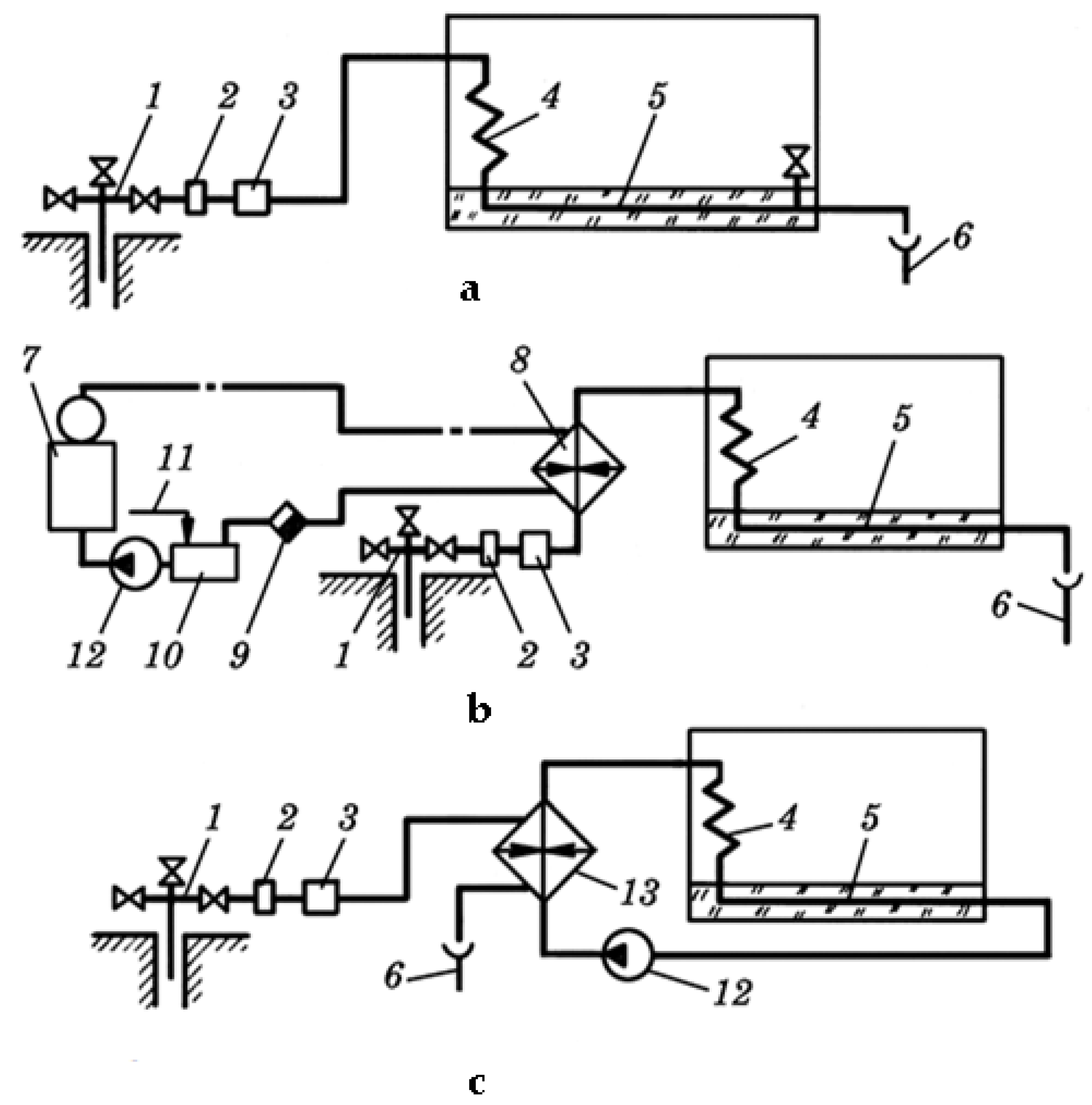
The following methods of using geothermal water are available for heating greenhouses:
Figure 2 shows a functional diagram of a geothermal heating system for greenhouses with a surface heat exchanger.
During the study, part of the heat supply system of the greenhouse complex was considered without taking into account the system that circulates the secondary heat transfer liquid in the heating circuit of the greenhouse. The considered subsystem includes the following elements: a geothermal well, an electric ball valve, a mud sump, a degasser, a feed pump, and a heat exchanger. The process of the heat supply system functioning is considered: the amount of incoming geothermal water from a well directly affects the temperature of the heat transfer liquid circulating in the heating circuit. To regulate the air temperature in a greenhouse, it is necessary to regulate the amount and speed of the incoming geothermal water. Electric ball valves controlled by PLC (programmed logical controller) are used for this purpose. Water enters into the sump and degasser, after which pumps supply water to the plate heat exchangers, where the heat carrier circulating directly in the heating circuit is heated. After the water passage through heat exchangers, cooled geothermal water is discharged.
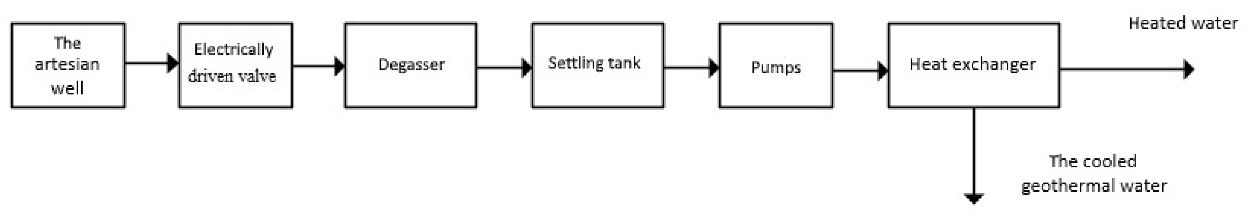
To simulate the system, we will draw up a functional diagram of the considered heat supply system without an acoustic–magnetic device, which shows the main elements (
Figure 3):
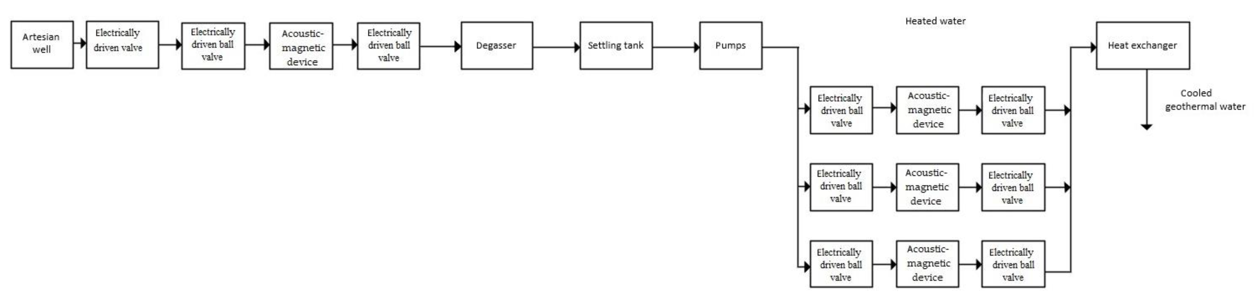
To ensure greater efficiency of the heat supply system, acoustic–magnetic devices were installed to prevent the formation of scale, which reduces the efficiency of the system. The functional diagram of the system using acoustic–magnetic devices is shown in
Figure 4.
To conduct a simulation of a system for water temperature automatic control, it is necessary to compile a mathematical description of the heat exchanger. In its simplest form, the heat exchanger can be represented as an aperiodic unit of the first-order. However, this model provides a large number of simplifications, and as a result, an inaccurate description of the functioning of the investigated object. There are various works that describe heat exchangers with different accuracy [
22,
23,
24]. The model [
25] is used since it is suitable for all types of heat exchangers.
The environment for mathematical simulation “Scilab 6.1” (a high-level, numerically oriented programming language), which has a tool “Xcos graphic systems”, is used to make the model. Define the main transfer functions of the links in the system [
26].
The transfer function of the electrically driven ball valve (with electric motor) for the regulating effects is:
where
= 0.5 rad/(s V) is transmission ratio;
= 0.35 s is the time constant.
The transfer function of the ball valve (with electric motor) to the disturbing effect is:
where
= 1.7 rad/(s V) is gear ratio;
= 0.55 s is the time constant.
Electrically driven ball valve transfer function (reducer) is:
The transfer function of the electrically driven ball valve (working mechanism) is:
where
= 1.9 V s/rad is the gear ratio.
The sump transfer function is:
where
= 0.85 is the transfer gain.
The degasser transfer function is:
where
= 0.98 is the transfer gain.
The transfer function of actuator 1 (primary circuit pump) is:
where
= 0.3 is gear ratio;
= 0.25 s is the time constant.
The transfer function of actuator 2 (secondary circuit pump) is:
where
= 0.0023 is gear ratio;
= 0.2 s is the time constant.
The transfer function of the process of scale formation in the heat supply system is:
where
= 0.38 is gear ratio;
= 1.8 s is the time constant.
An aperiodic link with a coefficient of 0.86 was used as the transfer link of the acoustic–magnetic device. This value is equal to the efficiency of the device, determined from previously conducted experiments [
21].
The transfer function of the acoustic–magnetic device installed in the geothermal heat supply system of the greenhouse complex is:
where
= 0.86 is gear ratio;
= 2 s is the time constant.
The transfer function of electrically driven ball valve:
where
= 0.68 is gear ratio;
= 9.6 s is the time constant.
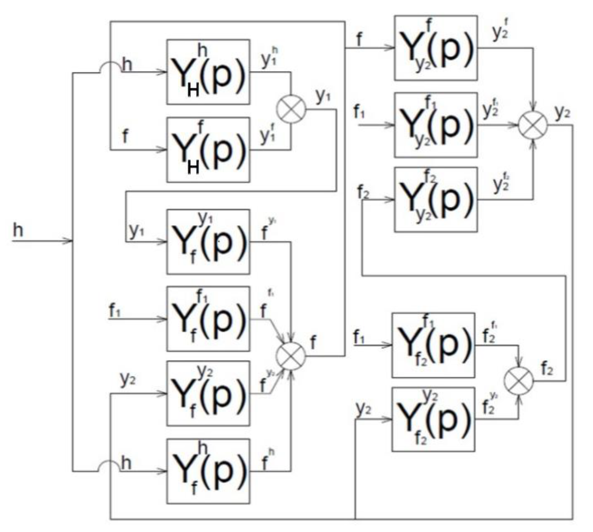
Let define the main transfer functions of the links in the system. According to the representation of the heat exchange installation (
Figure 5), the transfer functions with respect to
and
, which are responsible for the primary and secondary circuit, respectively, have the form:
where
is the transfer function on h;
is the transfer function on f;
is the transfer function on h;
is the transfer function on
;
is the transfer function on
;
is the transfer function on
;
is the transfer function on
;
is the transfer function on
;
is the transfer function on
;
is the transfer function on
;
is the transfer function on y.
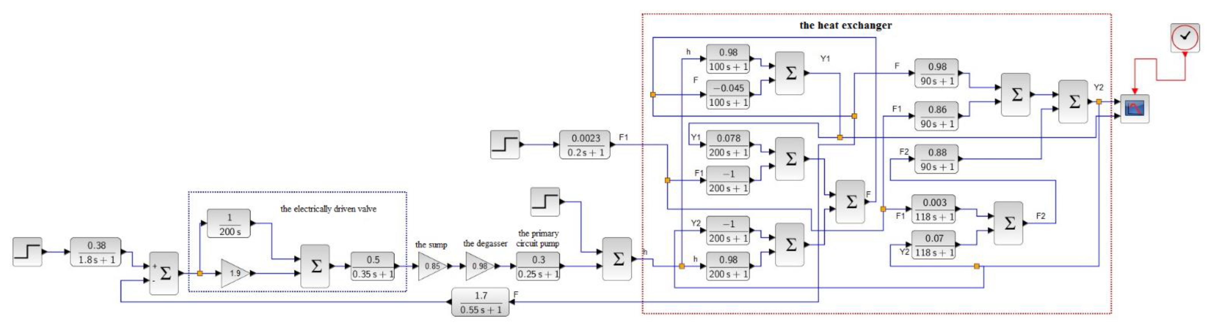
The temperature change of the heat transfer liquid emerging from the heat exchanger and entering the main circuit of the heat supply system is interesting for research. According to the functional diagram using the universal heat exchanger model presented in [
25], the heat exchanger model in the researching heat supply system was implemented, presented in
Figure 6.
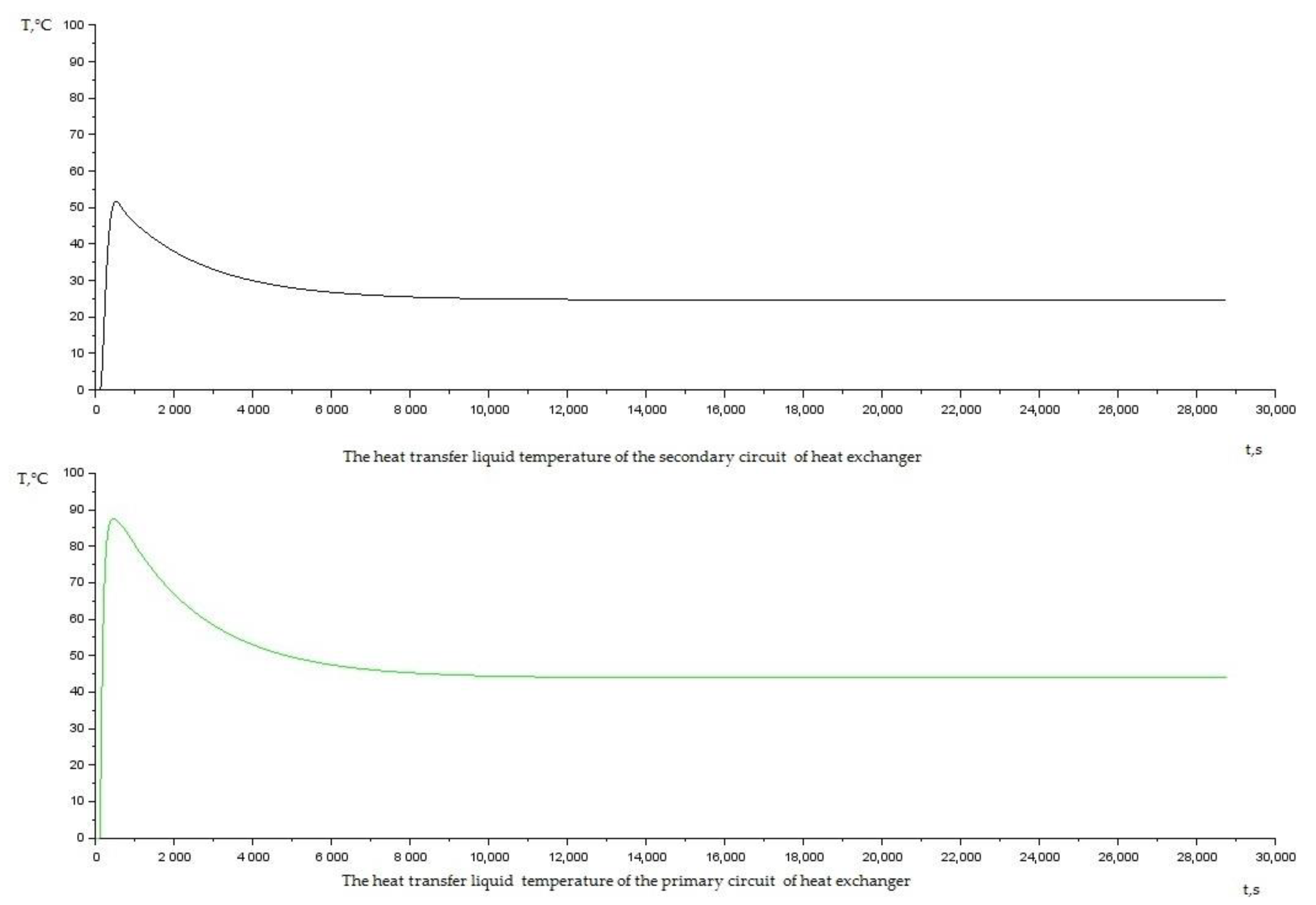
The temperature of geothermal water coming from the well is considered as an input variable. The average temperature of the water is 86 °C (in the range of 80–90 °C, depending on the time of year and other conditions). The picture of the temperature of the primary and secondary heat transfer liquids in the heat exchanger behavior was obtained with visualization tools. It is presented in
Figure 7.
It can be seen from the obtained graphs that during prolonged use of the heat exchanger its efficiency, decreases due to scale formation, which leads to a deterioration in heat transfer. The primary heat transfer liquid (heat carrier) temperature change is determined by the deterioration of the operation of electrically driven valves due to the diameter of the pipeline decreasing.
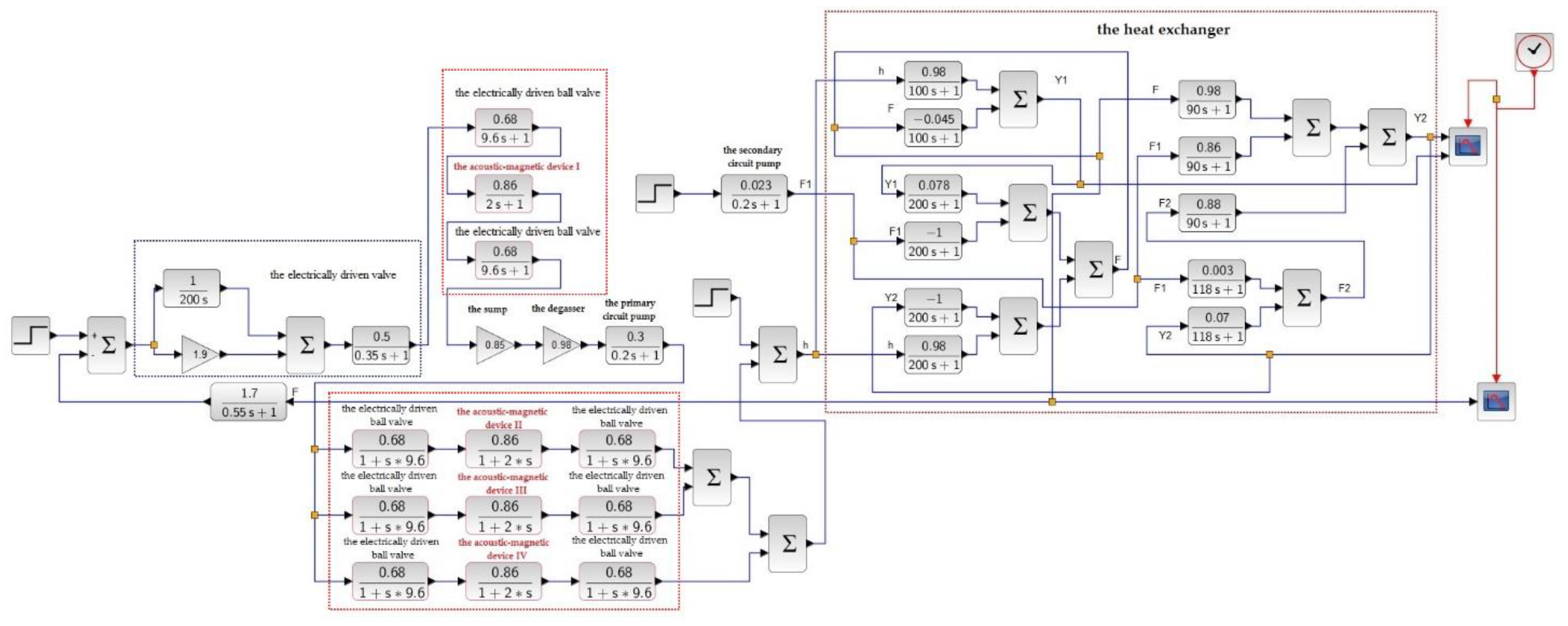
After the inclusion of an acoustic–magnetic device in the simulated system, the new model of the process was built (
Figure 8).
The new model (
Figure 8) was considered without taking into account the factor of scale formation because experiments had confirmed the absence of scale when using acoustic–magnetic devices in the heat supply system. The acoustic–magnetic devices were installed in parallel after the primary circuit pump. Ball valves, installed in series with each device, turn on and off the acoustic–magnetic devices in the primary circuit of the heat exchanger. It allows achieving optimal modes of acoustic–magnetic treatment of geothermal water.
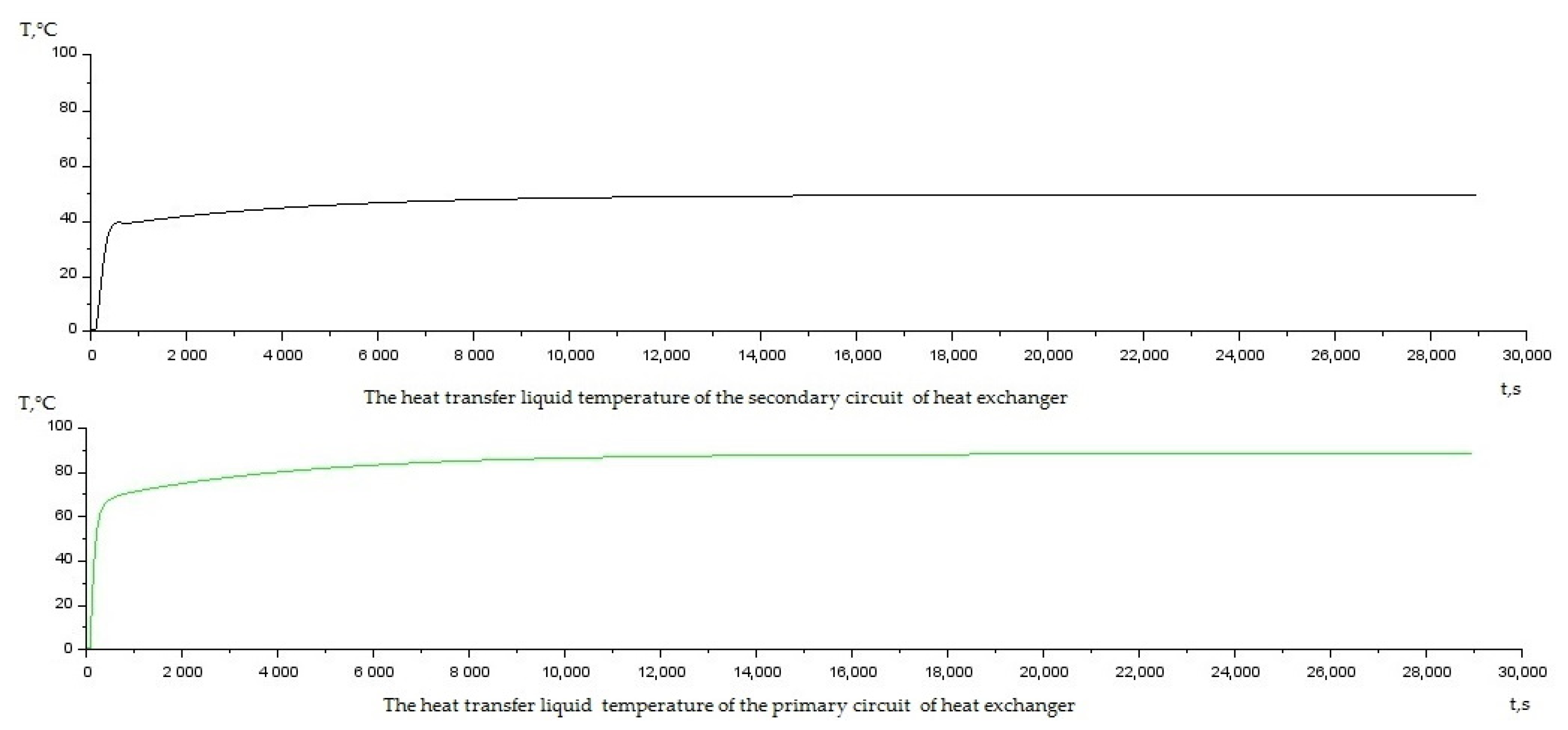
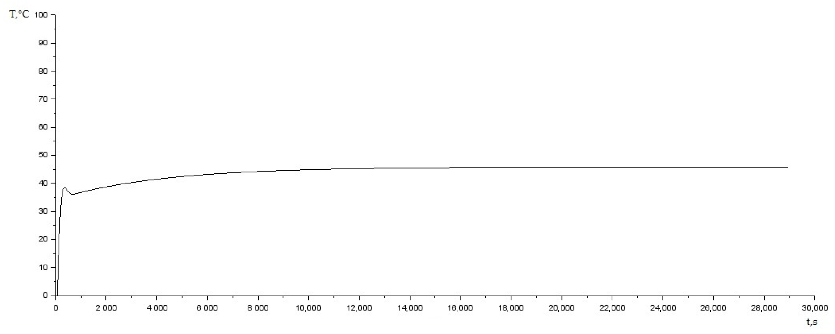
As a result of the simulation, a graph of the parameter behaviors studied was obtained (
Figure 9):
The graphs demonstrate that the temperature level of the primary and secondary heat transfer liquids does not change over a long period of time. This is due to a significant slowdown in the process of scale formation in the heat supply system. Based on the simulation results (
Figure 9) of a system with acoustic–magnetic devices, the following characteristics were obtained:
These characteristics demonstrate the stability and acceptable quality of the simulated system. The operating mode of automation system with acoustic–magnetic devices is stable for a long time interval.
3. Results
An acoustic–magnetic device enables a significant slow down of the scale formation process on the internal surfaces of heat-exchange equipment in heat supply systems (for 9 months and more). This device has greater processing efficiency than other magnetic devices. For example, the electrically driven valves continue to operate faultlessly after 2 years.
In accordance with the results of past studies [
22], it was found that the processing efficiency of this device in case of its correct operation reaches 90%. This compares with other magnetic water treatment devices, which have an efficiency of 40–45% [
27,
28,
29].
Traditionally, magnetic devices are used for the treatment of water and solutions. These devices parameters have conditional diameters (mm): 80; 100; 200; 600; nominal pressures (mPa): 1.6; capacity of processed water (m3 h−1): 25–600; magnetic field strength (kA m−1): 200; consumed power by the electromagnet (kW): 0.35–1.8; dimensions of the magnet (mm): 260 × 420; 440 × 835; 520 × 950; 755 × 1100; weight of magnet (kg): 40; 200; 330; 1000.
One magnetic device installed on a pipe with a diameter of 80 mm demonstrated a power consumption of 1.5 kW, weight 40 kg. Ten acoustic–magnetic devices demonstrate the power consumption of 70–100 watts, weight 8 kg. However, the performance for the processed water was the same (25 m3 h−1). The value of the magnetic field strength of the acoustic–magnetic device measured in the working area was 15 A m−1 with RMS = 1. The overall dimensions and power of the device were optimized.
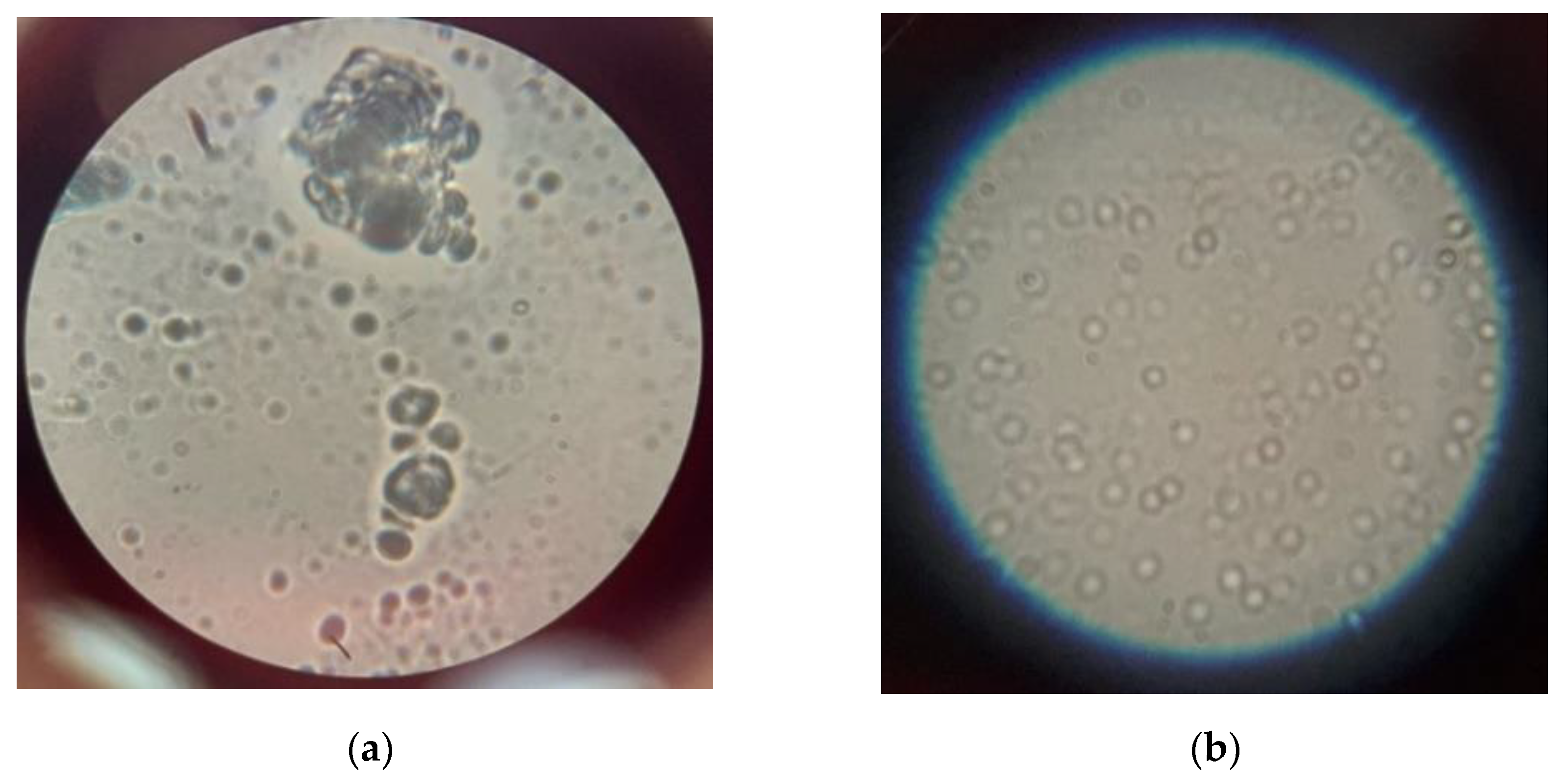
The effect on the crystallization centers of the acoustic and magnetic fields generated by the acoustic–magnetic device can be visualized (
Figure 11).
Figure 11 shows that untreated geothermal water, in contrast to the treatment with acoustic–magnetic device geothermal water, has obvious crystallization centers. Hence, we assume that acoustic–magnetic devices, acting on the crystals of salts, prevents their adsorption, thereby preventing the formation of solid deposits on the surfaces of the heat exchange equipment. The effectiveness of acoustic treatment is manifested in the prevention of the formation of primary crystals on the pipes.
The research carried out demonstrates the effectiveness of the use of reagentless treatment of geothermal water with an acoustic–magnetic device. The installation of these devices in the circuit of the geothermal heat supply system (
Figure 12) leads to a decrease in the frequency of system shutdown for unscheduled cleaning of the heat exchanger, which made it possible to reduce the labor intensity of manual operations of heat exchange equipment maintenance (removal of sludge, scale) and reduce the economic costs of transportation and heat consumption [
30,
31].
To determine the effectiveness of the anti-scale effect, various methods are used. The most obvious is the crystal-optical method [
32], according to which the anti-scale effect θ is determined by the formula:
H—the dimension of solid deposits (inclusion) for untreated liquid;
M—the dimension of solid deposits (inclusion) for treated with an acoustic–magnetic device liquid.
The values of average linear sizes of salt crystals in treated and untreated water were calculated by approximate calculation of the area of complex figures in relative unit measure. The value of the anti-scaling effect is:
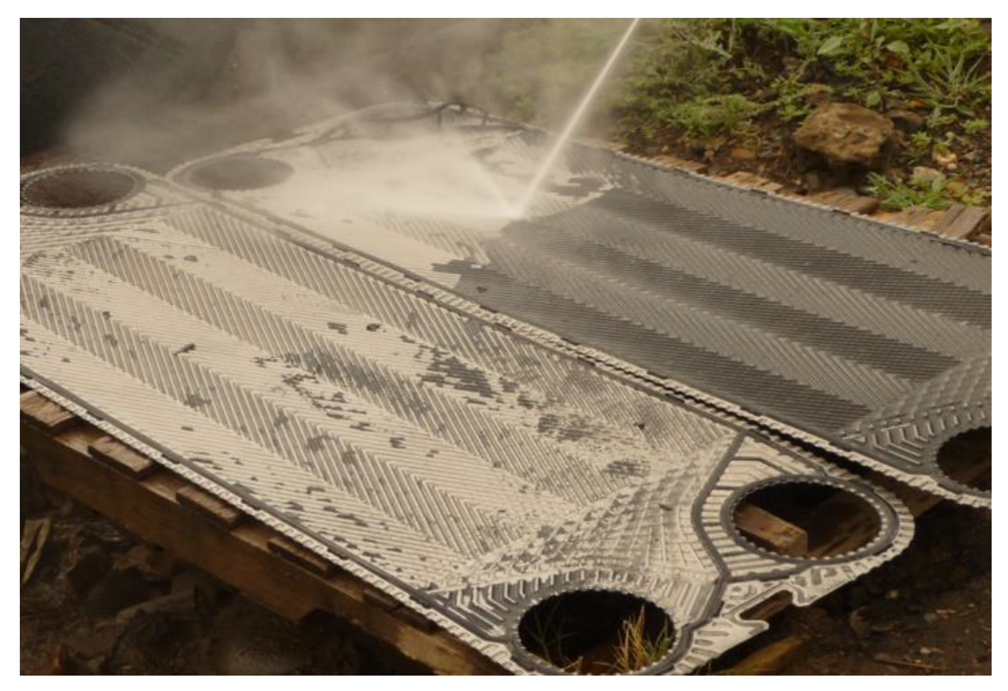
After a long period of exploitation of the equipment, a small amount of scale was deposited, which was removed easily mechanically (
Figure 13).
The discrepancy between the experimental and the simulation values of heat carrier temperature (in the heat supply system with acoustic–magnetic devices) was estimated using the formula
where
is the calculated error of the
;
is the simulated value;
is the experimental value.
The discrepancy of experimental and simulated data does not exceed 5%, which allows for confirmation of the validity of the simulation and fairly accurate correspondence to its physical prototype.
4. Discussion
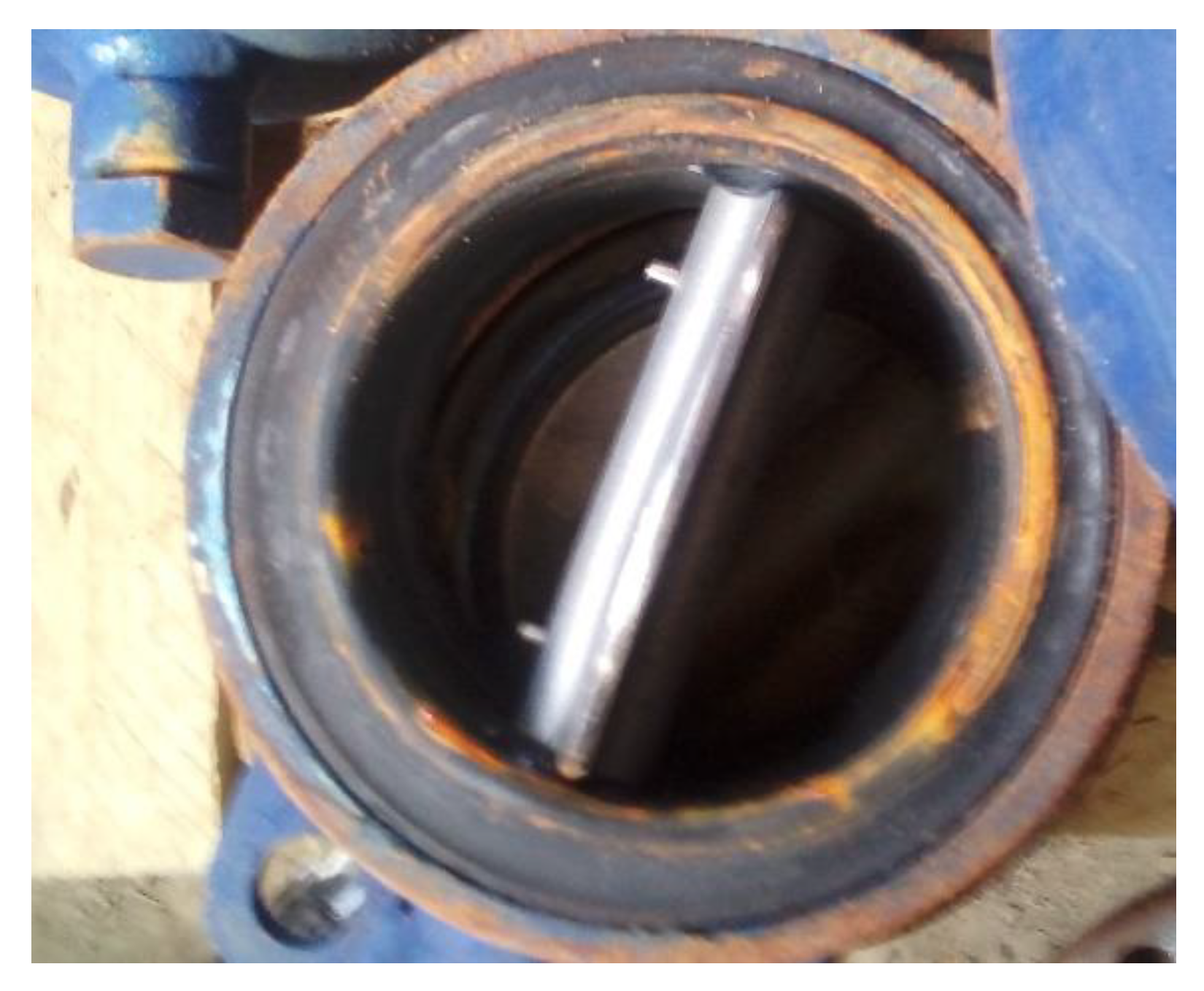
Intensive scale formation on the inner surfaces of the greenhouse heat supply system does not allow the installation of control elements of the automation system to regulate the temperature conditions of the greenhouse complex.
Figure 14 demonstrates a valve through which geothermal water flowed during the heating season. The problem is that the actuating elements of the automation system mechanically cannot move due to the formed deposits.
Sources [
33,
34] present extensive research on various technologies and applications of geothermal energy. However, a comprehensive assessment of geothermal heating systems is relevant due to changes in understanding, the scope of application and evolution, of technologies, which confirms the relevance of the research presented in the article.
Various models of acoustic–magnetic devices were designed for geothermal water reagentless treatment [
35]. They were tested at the geothermal deposits of the Maykop region of the Republic of Adygea. The devices for reagentless acoustic–magnetic water treatment were used successfully at JSC “Raduga”. These devices have the following characteristics: the amount of treated water is up to 0.25 m
3/s, consumed power is about 150 W.
Research (2016–2020) of equipment metal protection from corrosion and salt deposition methods with geothermal water reagentless treatment has significant practical interest. The acoustic–magnetic geothermal water reagentless treatment allows not only protecting the metal of geothermal heat supply system equipment from corrosion effectively but also removing the existing deposits of salts and corrosion products in heat exchangers, pipes and electric valves that disrupt their normal operation. The equipment downtime and the cost of human labor and material resources for troubleshooting main heating mains and pipelines determined by a violation of the water-chemical regime have decreased as a result. The problem of scale formation is solved by installing acoustic–magnetic devices that will make it possible to automate the heat supply system of the greenhouse complex.
The simulation results are consistent with the data obtained as a result of the installation of acoustic–magnetic devices. It is necessary to fulfill a number of conditions to install the acoustic–magnetic device. It will minimize the process of scale formation on the walls of pipes and heating equipment. The main condition is that the device must be installed at the outlet of the geothermal well before the degassing system. The number of installed devices depends on the diameter of the supply pipe, water consumption, and type of acoustic–magnetic device. All devices must be connected in parallel to each other and with sludge traps. For high hourly water flows, it is allowed to process up to 30% of the solution flow. Before installing the acoustic–magnetic device, it is necessary to revise the entire geothermal water supply system, replace pipelines, filters, and clean the old scale from the heat exchanger. Acoustic–magnetic devices and sludge separators are installed in such a way that they are always filled with geothermal water.
Figure 15 demonstrates a valve through which geothermal water from the Maykop field flowed during the heating season if geothermal water is treated with an acoustic–magnetic device.
For optimal operation of acoustic–magnetic devices, it is necessary to provide a fluid flow rate in the range of 1–3 m/s. An automatic reagentless geothermal water treatment system was installed for the hydroponic greenhouses heating system.
Figure 16 demonstrates the automatic reagentless geothermal water treatment system control cabinet.
In accordance with the peculiarities of the technology, equipment and the tasks of control of geothermal water reagentless treatment and on the basis of the general principles of building modern automatic control systems, the designed automatic control system of reagentless geothermal water treatment is capable of controlling the technological process; consumes a small amount of energy, has an acceptable level of reliability.


