Article

Development and Research of Crosshead-Free Piston Hybrid Power Machine

1
Hydromechanics and Machines Department, Omsk State Technical University, Prospect Mira st., 11, 644050 Omsk, Russia
2
Transport, Oil and Gas Storage, Standardization and Certification Department, Omsk State Technical University, Prospect Mira st., 11, 644050 Omsk, Russia
*
Author to whom correspondence should be addressed.
Machines 2021, 9(2), 32; https://doi.org/10.3390/machines9020032
Submission received: 16 December 2020 / Revised: 29 January 2021 / Accepted: 31 January 2021 / Published: 5 February 2021
(This article belongs to the Section Machines Testing and Maintenance)

Abstract

:
This article considers the development and research of a new design of crosshead-free piston hybrid power machine. After verification of a system of simplifying assumptions based on the fundamental laws of energy, mass, and motion conservation, as well as using the equation of state, mathematical models of the work processes of the compressor section, pump section, and liquid flow in a groove seal have been developed. In accordance with the patent for the invention, a prototype of a crosshead-free piston hybrid power machine (PHPM) was developed; it was equipped with the necessary measuring equipment and a stand for studying the prototype. Using the developed mathematical model, the physical picture of the ongoing work processes in the compressor and pump sections is considered, taking into account their interaction through a groove seal. Using the developed plan, a set of experimental studies was carried out with the main operational parameters of the crosshead-free PHPM: operating processes, temperature of the cylinder–piston group and integral parameters (supply coefficient of the compressor section, volumetric efficiency of the pump section, etc.). As a result of numerical and experimental studies, it was determined that this PHPM design has better cooling of the compressor section (decrease in temperature of the valve plate is from 10 to 15 K; decrease in temperature of intake air is from 6 to 8 K, as well as there is increase in compressor and pump section efficiency up to 5%).

1. Introduction

Pumps and compressors designed for the compression and displacement of low-compressible liquids and gases are widely used as in traditional industries: power, oil and gas, transport [1] and aviation, as in new ones: measuring equipment [2], medical industry, etc. In general, from the point of liquid and gas mechanics, “liquid” as a term includes low-compressible (droplet) liquid and compressible liquid (gaseous). They simply use “liquid” instead of “low-compressible liquid” as a term in the theory of pumps, and “gas” is used instead of “compressible liquid” in the theory of compressors. Thus, we also use “liquid” and “gas” in the article.
Due to the fact that 20% of the energy used in industry is spent on pump units’ drive [3], the task to increase their efficiency is important and relevant.
At present, one of the main ways to increase the work efficiency and effectivity of compressors and displacement pumps, as well as to improve their weight and size indicators, is to unite them into a single unit called a piston hybrid power machine. Piston hybrid power machines have the leading role among variety of hybrid power machines. When a pump and a compressor are combined into a single power unit, the compressor cooling is improved, leaks and overflows of the compressed gas are eliminated in the cylinder–piston group, friction forces are reduced in the cylinder–piston group, positive suction head is increased, and gas compression heat is to be utilized in the pump section [4]. There are two main line diagrams among hybrid power machines.
The first diagram is a crosshead hybrid power machine (see Figure 1), in which a disk piston divides the working space of the cylinder into two working chambers: the compressor section is located above the piston and the pump section is located under the piston.
The second diagram has a differential piston and two working chambers. The inner working chamber is a compressor section, and the external working chamber is a pump section (see Figure 2).
Design, development, and research of the crosshead PHPM operation are given in [4]. Experimental and numerical studies of crosshead PHPM with various types of groove seals were carried out there. Findings presented that the crosshead PHPM with a step-like groove seal is the most effective. The crosshead PHPM defects are:
-
Poor cooling of the cylinder–piston group and the compressed gas;
-
Many moving parts with reciprocating movement;
-
Specific weight and size indicators have low values.
These defects are partially eliminated in the crosshead-free PHPM [5].
We developed a new powerful design of crosshead-free PHPM based on the analysis of the above-mentioned defects typical for crosshead and crosshead-free PHPM; its line diagram is shown in Figure 3.
In the developed PHPM, there is annular П-shaped protrusion 16 installed on piston 5 forming two working chambers with the inner surface of outer cylinder 7 and outer surface of inner cylinder 17: working chamber 15 is for gas compressing and moving, working chamber 21 is for liquid compressing and moving. Inner cylinder 17 is mounted concentrically to outer cylinder 7. Pipe 10 is for gas supply and pipe 13 is for its removal in inner cylinder 17. The pipes have suction valve 8 and discharge valve 9, which allow gas to be sucked into working chamber 15 of the compressor section and its supply from the working chamber to the consumer. There are pipes in inner cylinder 17, where suction valve 11 and discharge valve 12 are installed; they supply liquid to the working cavity of pump section 21 and then to the discharge.
The developed assembly of the power machine, including inner cylinder 17 centered relative to working surface of cylinder 7, produces parallel cylindrical surfaces; piston 5 is centered with П-shaped annular protrusion 16 along them. Both external and inner working surfaces of П-shaped protrusion 16 are cylindrical surfaces of one part located on the same axis and can be made concentrically in one assembling on processing equipment.
Reed valves were used as gas distribution bodies in the compressor section; their photos are shown in Figure 4.
The inner cylinder of the compressor section (Figure 5, item 2) is T-shaped and is shown in Figure 6. It has pipes for connecting suction and discharge lines to valve plate 8 of the compressor section; the valve plate is installed in the lower part of inner cylinder 2. Holes are made in the pump cavity in the upper part of inner cylinder 2; they are united by crescent-shaped windows for connection with the suction and discharge lines of the pump.
The crosshead-free piston hybrid power machine operates as follows (see Figure 3): when piston 5 with annular П-shaped protrusion 6 mounted on it is up (from bottom dead center to top dead center), gas is compressed in working cavity of compressor section 15, and liquid is compressed in the working cavity of pump section 21. When the nominal discharge pressure is in the pump section, valve 12 opens, and the liquid flows from cavity 21 to the consumer. With further upward stroke and reaching the nominal gas compression pressure in the working cavity of compressor section 15, discharge valve 9 opens, and gas flows to the consumer through pipe 13.
Thus, when the piston moves upward, liquid and gas are compressed and move to the discharge; it should be noted that the discharge valve of the pump section opens earlier than the discharge valve of the compressor section and the liquid is supplied to the discharge from the pump section at a larger crank angle. When the piston reaches the top dead center, the discharge valve from the pump section and compressor section closes, and the flow of liquid and gas to the discharge stopped. When the piston moves down (from top dead center to bottom dead center), there is an expansion process and a pressure drop to the suction pressure in the pump and compressor section. Then, with a further piston stroke, the suction valves open (11—in the pump section, 8—in the compressor section), and working chambers 21 and 15 are filled with liquid and gas.
The process of back expansion is much shorter in the pump section than in the compressor section, and suction valve 11 opens in the pump section before suction valve 8 of the compressor section opens. Then, the cycle repeats.
The certain advantages of this diagram are enhanced cooling of the cylinder–piston group and compressed gas, as the pump section is located around the compressor section and there are pipes operating as heat exchangers in the valve plate. This design should reduce the temperature of suction gas, improve the compressed gas cooling, and have high economic efficiency as well as specific weight and size indicators.
Currently, when simulating the working processes of compressors and displacement pumps, mathematical models with lumped and distributed parameters are used [6,7,8]. Unlike vane machines [9,10], models with lumped parameters are most widely used in displacement machines. This is due to following reasons:
-
Working chamber volume and boundaries change, the computational grid is to be rebuilt constantly, and it complicates the implementation of existing software for non-steady flow of viscous compressible liquid as for laminar and turbulent flows;
-
Linear dimensions of positive displacement machines are rather small, so there is no need to use models with distributed parameters, as when there are small linear dimensions, uneven distribution of thermodynamic parameters is very small in the working chamber. This is true for displacement pumps, as the speed of sound (speed of propagation of simple waves of compression and expansion) is greater than in gas;
-
The existing patterns of distribution of thermodynamic parameters in the working chambers of compressors and displacement pumps according to the angle of rotation are well-known, and researchers are often interested in averaged parameters at each point of the process under study. Therefore, when using models with distributed parameters, averaging at each angle of rotation is to be carried out, and the results of averaged thermodynamic parameters will be close to the thermodynamic parameters obtained when using models with lumped parameters;
-
Costs of material and physical resources necessary for the development and implementation of models with distributed parameters are higher than for models with lumped parameters;
-
The time to implement models with distributed parameters is higher than the time to implement models with lumped parameters; the difference in the results is nominal [6,7].
Thus, the aim of this article is a comprehensive numerical and experimental study of a crosshead-free piston hybrid power machine to identify the main physical laws in work processes and to establish the influence of the main operational parameters on the work processes and integral characteristics of the machine for their further use in the development and operation of the machine.
The results obtained on the cooling of the cylinder–piston group and the work processes of the machine under study are to be compared with the results of previous studies for crosshead PHPM. The article will make a significant contribution to the study of the work processes of PHPM and will be useful for readers engaged in the research and design of reciprocating compressors, pumps, and hybrid power machines.

2. Mathematical Simulating of Work Processes of the Machine

Considering the above aspects, it seems appropriate to use a model with lumped parameters when developing mathematical models of a crosshead-free PHPM. The scheme of the crosshead-free PHPM is shown in Figure 7.
When developing a mathematical model of work processes, we distinguish three main stages: the mathematical model of the compressor section (see Figure 7, item 3); the mathematical model of the pump section (see Figure 7, item 1); and the mathematical model of a piston seal (see Figure 7, item 2) connecting the pump and compressor sections. The allocated working volumes in figures are shown with dashed lines.

2.1. Mathematical Simulation of Work Processes of Compressor Section

Based on the analysis of existing assumptions accepted when constructing the mathematical model of displacement compressors with lumped parameters, we accept the following system of assumptions without additional justification [11]:
-
Simulated processes are reversible and equilibrium.
-
Working liquid is continuous.
-
Liquid entering the working chamber is localized as liquid layer on the piston surface.
-
Compressible gas is clean air.
-
Changing in gas potential and kinetic energy is negligible.
-
Working liquid is perfect gas.
-
Heat exchange of the working liquid with the walls of the working chambers of the compressor section is carried out only by convection and is described by the Newton–Richmann hypothesis.
When simulating mass flows through valves and leaks, there are assumptions typical for mathematical models with lumped parameters [12,13]: gas flow is one-dimensional, isotropic; dependencies for steady flow are used to describe the flow; flow coefficients obtained with stationary purges are used, etc.
Operation of a piston hybrid power machine can be carried out in the following main modes:
-
PHPM operating mode with priority liquid flow from the pump section to the compressor (discharge pressure in the pump section is equal or higher than the discharge pressure in the compressor section);
-
PHPM operating mode with priority gas flow from the compressor section to the pump section (discharge pressure in the compressor section exceeds the discharge pressure in the pump section);
-
PHPM operating mode with equality of liquid mass per cycle from the pump section to the compressor section and back (the discharge pressure in the compressor section and the pump section are comparable).
The first and third modes of PHPM operation are the most effective. Implementation of the third mode is very difficult, so the first two modes of operation are the most practical. We consider a mathematical model of work processes in the compressor section with priority liquid flow from the pump section to the compressor.
The following basic fundamental laws are the basis of the mathematical model of the compressor section work processes:
-
Energy conservation equation as the first law of thermodynamics of a variable mass body;
-
Mass conservation equation;
-
Equation of motion;
-
Equation of state.
The system of differential equations in full derivatives describing changes in thermodynamic parameters of gas in the compressor section is written as:
{ d U =   d Q p ( d V k i n d M 16 d M 17 ρ w ) + i = 1 N 1 i n i d M n i i = 1 N 2 i 0 d M 0 i d M = i = 1 N 1 d M n i i = 1 N 2 d M 0 i = d M 3 d M 4 + d M 5 + d M 10 d M 9 p = ( k 1 ) U / V T = p V / M R m s p r d 2 h c d τ 2 = i = 1 F i = F g + F s p r + F f r ± m s p r g
where d U = d ( C v M T ) ; d V k i n = υ p F p d τ is elementary change in the control volume due to the kinematics of the drive mechanism; υ p = S h 2 ω ( sin ϕ + λ t 2 sin 2 ϕ ) ; F p = π d 1 2 4 ; i n i = C p i T n i .
There is heat exchange between the compressed gas and the surface of the walls of the working chamber in the working chamber of the compressor section, as it is between the gas and liquid layer above the piston. Then, an elementary amount dQ, diverted from the compressed gas is determined as
d Q = α ¯ T ( F c l + F cov ) ( T ¯ a v t T ) d τ + α ¯ T F p ( T ¯ w T ) d τ
where F c l = π d ( S δ ) ; S = S d + S h 2 [ ( 1 cos ϕ ) + λ t 4 ( 1 cos 2 ϕ ) ] .
The distribution of the temperature field over the surface of the cylinder liner and the surface of the valve plate cover is complex and not stationary over time. The performed studies prove that temperature fluctuations of the cylinder bore and surface of the valve plate are less than 1 K for single-acting compressors, so we assume that the temperature distribution field is stationary. In most cases, the temperature distribution fields are determined experimentally [14].
The averaged integral temperature T ¯ a v t is determined as
T ¯ a v t = 0 F cov T cov ( F ) d F + 0 F c l T c l ( F ) d F F c l + F cov .
The value of the liquid temperature above the piston, as well as the surface of the walls of the working chamber, has an uneven distribution over the surface and in time. However, this unevenness is very small and can be neglected.
The value of the liquid temperature can be considered constant and equal to the temperature of the liquid in the pump section. The heat transfer coefficient is a variable at each point on the surface of the working chamber. While calculating the averaged over the surface heat-transfer coefficient that has been adopted, its value is determined experimentally based on [6,15,16]. While determining the mass flows through the valves, the Bernoulli equation is used with the introduction of correction factors to consider the compressibility of gases. Movement of the blocking element is considered as unsteady movement of a material point with effective mass. Movement of the blocking element is plane-parallel, perpendicular to the seating under the influence of differential pressure and spring [17].
When gas is completely displaced from the working chamber of the compressor section, liquid is displaced from the working chamber, and the compressor section works in the pumping mode. Liquid from the working chamber of the compressor section enters the suction line through leaks in the suction valve dM4w, through the discharge valve to the discharge line of the compressor section dM5w, through leaks of the piston seal and into the working chamber of the pump section dM17. For calculations, we assume that the liquid temperature in the working chamber of the compressor section remains constant (Tw = const).
Figure 7 shows the mass flows of gas and liquid for compressor and pump sections through the main elements of the machine (pressure and suction valves, piston seal) in forward and reverse directions. If forward flow is determined, e.g., mass flow dM9, then dM10 is assumed to be zero and vice versa, if dM10 is determined, then dM9 is assumed to be zero. The direction of gas and liquid flow was determined by the pressure gradient.
In this case, only deformation and mass transfer interaction will be observed in the working chamber and in accordance with [18] pw, pressure is determined as
p w = p w d + E w ( n V w 0 V w + n M w M w 0 ) .
The system of equations describing change in the thermodynamic parameters of liquid is written as
{ V w = V h 2 [ ( 1 cos ϕ ) + λ t 4 ( 1 cos 2 ϕ ) ] + V d c p w = p w d + E w ( n V w 0 V w + n M w M w 0 ) d M w = i = 1 N 4 d M w n i i = 1 N 5 d M w 0 i = d M 6 w d M 4 w d M 16 . T w = c o n s t m s p r d 2 h c d τ 2 = i = 1 N 6 F w i
It should be noted that acting forces on the blocking element i = 1 N 6 F w i when injecting liquid are the same as when injecting gas. However, their definition differs and will be considered later when there is simulating of work processes in the pump section.
Elementary masses of liquid passing through the valves can be determined as
d M w 0 = α g r w f g r ρ w ( p w p i ) d τ .

2.2. Mathematical Model of the Work Processes of the Pump Section

The main assumptions while developing a mathematical model of the pump section work processes are written as follows:
-
The working liquid of the pump section is viscous compressible dropping liquid that follows the laws of Newton and Hooke.
-
Mass transfer processes at the gas–liquid interface can be neglected.
-
The interface between liquid and gas is a plane parallel to the earth.
-
Coefficients of local resistances and the coefficient of friction along the length obtained in stationary modes of liquid flow can be used in unsteady flow.
Displacement pump cycle consists of four processes: compression, discharge, reverse expansion, and suction. According to physical phenomena, four processes can be divided into two groups. The first group includes compression and expansion. In these processes, an increase (decrease) in pressure occurs due to deformation interaction. The second group includes processes of discharge and suction. Mass transfer has a decisive effect.
It should be noted that all four processes are connected with thermal interaction, which is insignificant and neglected. We made a sequential review of the calculations of the above work processes.
Compression and reverse expansion processes
In the processes of compression and reverse expansion, the processes of deformation (reduction in the working chamber volume due to piston movement), mass transfer (leaks and leakage of liquid), and heat transfer (convective heat transfer with surface of the walls of the working chamber) interactions take place when there is no liquid movement, i.e., kinetic energy.
The main fundamental work on the calculation of compression and reverse expansion processes is [19]. Recently published work [18] continues [19] and determines the change in pressure in the working chamber as if there is separately deformation, mass transfer, and thermal interactions, as in their combination.
Due to the fact that change in liquid temperature is very small in the processes of compression and reverse expansion, the system of equations written in [19] can be converted as:
{ V w = V d w + V h 2 [ ( 1 cos ϕ ) + λ t 4 ( 1 cos 2 ϕ ) ] d M w = i = 1 N 3 d M n i w i = 1 N 4 d M 0 i w p w = p s c w + E w ( n V s c w V w + n M w M s c w ) T w = c o n s t
where V s c w = V d w + V h p ; V h p = π 4 ( d 2 2 d 1 2 ) S ; M s c w = V s c w ρ w , V h = S h π ( d 2 2 d 1 2 ) 4 .
The current liquid mass change is determined as
d M w = d M 12 + d M 14 d M 17 .
Mathematical model of discharge and suction
Deformation, mass transfer, and thermal interactions are followed with conversion of the flow kinetic energy into pressure potential energy and back in the processes of discharge and suction.
A method was developed in [20] for calculating the processes of discharge and suction based on the first law of thermodynamics for an open moving thermodynamic system.
The calculation is carried out in two stages. At first, using the Bernoulli equation, we determine change in liquid pressure in the working chamber of the pump as a result of conversion of potential energy into kinetic and pressure loss (pressure process). At the second stage using the first law of thermodynamics, we determine change in temperature and pressure of the working liquid due to deformation, heat, and mass transfer processes; then, we determine the change in pressure, temperature, and mass of the working liquid.
Considering that the external heat transfer is insignificant, the compressibility of the droplet liquid is insignificant, and leakages and overflows of the working liquid are small compared to the main flow; thus, the Bernoulli equation supplemented by the equation of dynamics of a self-acting valve in a single-mass formulation [21] should be based on the calculation
{ p w = p w d + ρ w g ( S D w + S w ) cos α + ρ w w 2 2 w 1 2 2 + Δ h T 1 2 + Δ h 1 2 m d r w d 2 h w d τ 2 = i = 1 N 6 F i w .
The pressure loss due to inner friction is the sum of pressure loss along the length and the pressure loss to overcome local resistance.
Δ h 1 2 = Δ h + Δ h ζ
Values Δ h and Δ h ζ are determined according to Darcy–Weisbach law
Δ h = λ f r ( S D w + S w ) d 1 w 1 2 2 g
Δ h ζ = w 1 2 2 g
where λ f r is length friction coefficient determined using [22,23].
As first approximation, we can assume that the main pressure losses occur during a sudden flow expansion in the valve, which can be determined as
ζ = ( 1 f g r / f 2 ) 2
where f g r = π d v l h w ; f 2 = π d p 2 4 .

2.3. Mathematical Model of Liquid Flow in a Groove Seal

The compressor and pump sections of the PHPM are interconnected by a groove seal, where there is always liquid under the PHPM investigated operation mode, and gas breakthrough from the pump section into the compressor section is impossible. In general, the flow of viscous liquid in a groove seal is unsteady and not axisymmetric, because pressure in pump and compressor sections varies in angle of rotation, and the piston has an eccentricity. The dynamics of liquid movement in a groove seal is as follows:
(1)
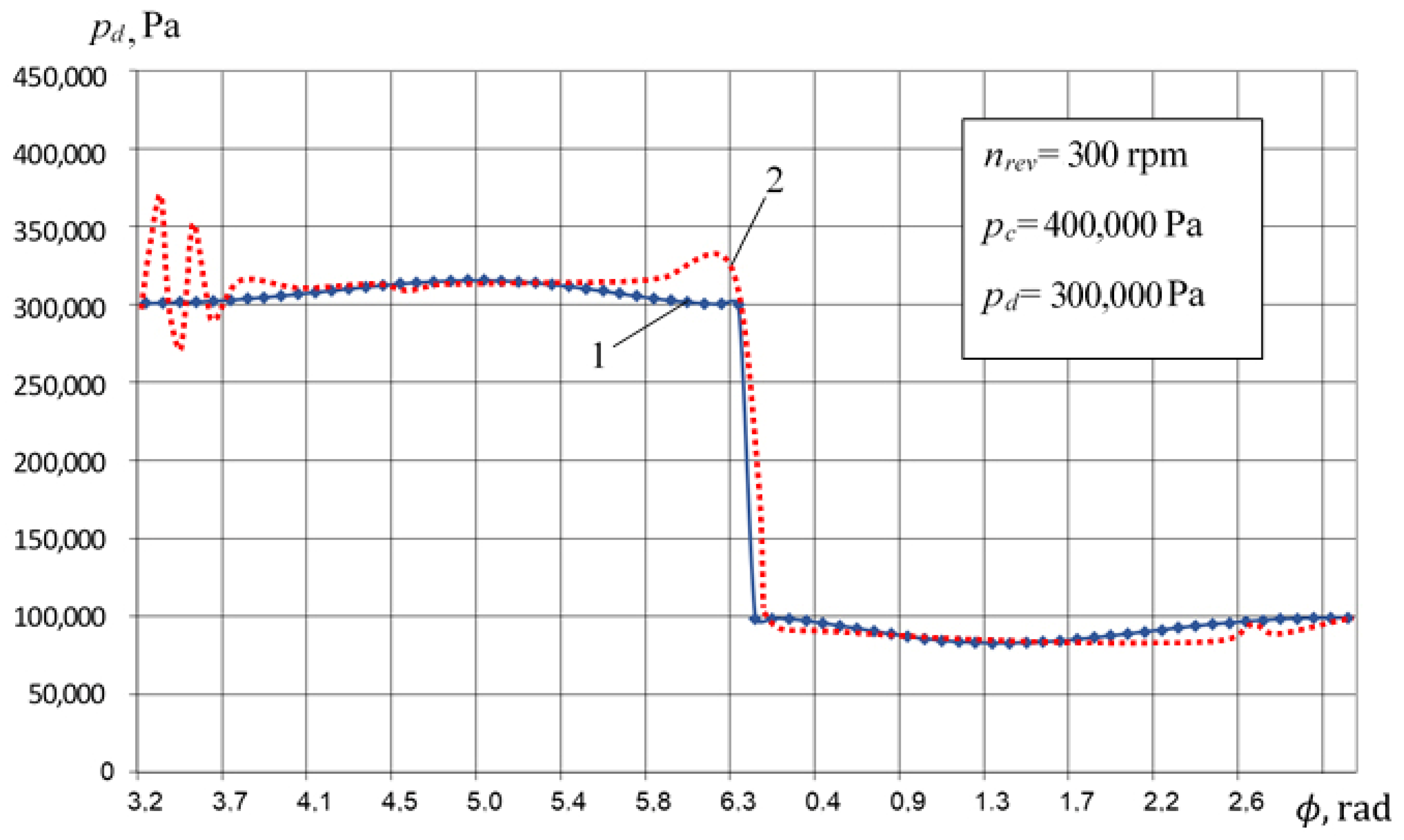
When the piston moves at an angle of rotation from π ϕ 2 π , compression processes are in the pump and compressor cavities. Initially, as the pressure in the pump cavity increases much faster than in the compressor, liquid from the pump section flows through the groove seal into the compressor and forms a liquid layer above the piston.
(2)
If the pressure is equal to pdp = pc, liquid movement into the compressor cavity ceases and then, when the pressure in the compressor cavity pc exceeds discharge pressure pdp in the pump, liquid flows from the compressor cavity to the pump.
(3)
When the piston moves from 0 < φ < π, there is suction in the compressor and pump cavities. If suction pressure in the compressor and pump section is equal, then there is no liquid movement in the groove seal. There is liquid movement from the compressor cavity to the pump as the pressure loss in the pump section during suction is more than that in the compressor.
In general, the liquid flow in a groove seal is described with a system of equations that includes the continuity equation, the equation of motion of viscous liquid, the energy conservation equation, and the equation of state.
Considering the above approach to simulate PHPM work processes, we consider liquid flow in a groove seal as laminar and quasistationary with constant liquid properties and groove geometry.
At present, various types of groove seals are used in PHPM: smooth, step-like, and profiled. The analysis of the PHPM groove seals operation proves that a smooth groove seal will be the most effective for a crosshead-free PHPM. We carry out the calculation for two principal cases: the concentric arrangement of the piston with and without friction movement and the eccentric arrangement of the piston without friction [24,25].
The task of calculating the piston seal is to determine the flow coefficient through the groove seal.
With concentric arrangement of the piston, the flow coefficient is determined as
Q = π d 1 δ 1 3 ( p c p w ) 12 μ u ± 1 2 υ p π d 1 δ 1 .
With an eccentric arrangement of the piston the flow coefficient is determined as
Q = π d 1 δ 1 3 12 μ u ( p c p w ) ( 1 + 3 / 2 ε 2 ) .
It should be noted that the length of the piston seal in the compression and discharge processes increases, and the instantaneous flow coefficient decreases. The current piston seal length u is determined as
u = u 0 + { S h S h 2 [ ( 1 cos ϕ ) + λ t 4 ( 1 cos 2 ϕ ) ] } .  

3. Experimental Study

The main aim of the experimental research is to obtain new knowledge about the object under study and to verify the developed mathematical model. That is why an experimental model of a crosshead-free PHPM was designed.

3.1. Object, Stand for Its Research, Measuring Equipment

The developed experimental model of crosshead-free PHPM has the following main design and operational parameters:
-
Inner diameter of the piston is 55 mm;
-
The outer diameter of the piston is 65 mm;
-
Connecting rod length is 81 mm;
-
Piston stroke is 47 mm;
-
Total piston length is 119 mm;
-
Discharge pressure in the compressor section is up to 10 bar;
-
Discharge pressure in the pump section is up to 20 bar;
-
Crank angular velocity is from 250 to 750 min−1;
-
Suction pressure in the pump section is 1 bar;
-
Suction pressure in the compressor section is 1 bar.
When designing a crosshead-free PHPM, the Solid Works software was used. Air was used as working liquid for the compressor section, and MGE-46V hydrolic oil (specifications are shown in Table 1) was used for the pump section.
The prototype was tested at the developed stand to perform the following functions:
-
To change smoothly the speed of the drive shaft while fixing the frequency of the piston reciprocating movement;
-
Measurement and maintenance of stationary parameters on the lines of liquid and gas suction and discharge;
-
Measurement of instantaneous values of pressures in working chambers with their indicator diagrams in digital and graphic forms;
-
Measuring the productivity of gas and liquid working chambers;
-
Measurement of leaks of working liquid;
-
High ergonomics to influence the main initial parameters;
-
Measuring the temperature of gas and liquid at suction and discharge, the temperature of the inner surface of the valve plate of the compressor section.
A hydropneumatic diagram of the stand is shown in Figure 8.
To change the speed of rotation of the drive shaft, a displacement hydraulic drive is used, which includes a displacement axial piston pump model 313.3.56.804 with a discharge pressure 6.3 MPa and an axial piston hydraulic motor 310.3.56.01.03.V.U. model. Static pressures are measured with pressure gauges; instant pressures are measured with tensometric sensors.
To reduce the unevenness of the pump cavity supply, a pneumatic accumulator with a Danfoss MBS 3000 (Danfoss, Chelyabinsk, Russia) pressure sensor is installed on the discharge line. The same sensor is used to measure the liquid suction pressure. Liquid flow rates are measured with TPR 20-8 (“Arzamas instrument-making plant named after P.I. Plandin”, Chelyabinsk, Russia) flow meters, suction and discharge temperatures are measured with TW N PT100 (Autonics, Chelyabinsk, Russia) sensors, and the liquid temperature in tanks is controlled with DTS 035 50M.V3 (OVEN, Chelyabinsk, Russia) sensors. Leakage is measured with volumetric method.
Air flow is measured with SMCPF2A751-F04-67N-M (SMC Corporation, Lukhovitsy, Russia), Vector-04 (NPP SKYMETER, Chelyabinsk, Russia), and SGV-15 Betar model flowmeters (OOO PKF “BETAR”, Chelyabinsk, Russia) at suction and discharge of the compressor cavity; we used PSE530 M5 l sensors (SMC Corporation, Lukhovitsy, Russia) for measuring suction and discharge pressures. An AD22100 STZ sensor (Analog Devices, Chelyabinsk, Russia) is used to measure the stationary temperature of the valve plate and the upper part of the cylinder.
The hydraulic and pneumatic lines of the stand are equipped with liquid and gas purification devices, safety devices, and controllers to organize the work of the tested machine in different modes. A general view of the tested machine installed on the stand is shown in Figure 9.

3.2. Verification of the Mathematical Model of Work Processes of Crosshead-Free PHPM

Verification of the developed mathematical model is based on the qualitative and quantitative matching of the results of numerical simulating and experimental studies; i.e., it is to verify that the mathematical model responds to changes in operational parameters and how it describes the work processes and integral parameters of the compressor and pump sections.
Verification of the developed mathematical model was confirmed over the range of changes in the independent parameters: pdp, pdc, and nrev.
We compared the indicator diagrams in the compressor and pump cavities, the main integral characteristics: compressor section feed coefficient, volumetric efficiency for the pump section, and the amount of liquid carried into the discharge line of the compressor section.
Figure 10, Figure 11, Figure 12 and Figure 13 compare indicator diagrams for the compressor and pump sections at different nominal discharge pressures.
A comparative analysis of the indicator diagrams in the compressor section proves:
-
Discrepancy in determining instant pressure is insignificant in compression, expansion, and suction, and it is less than 5%.
-
Maximum discrepancy from 10% to 15% is observed during discharge, due to significant inertial forces acting on the liquid when the valve is opened, leading to a significant pressure jump in the experimental data.
We compared indicator diagrams in the pump section and made conclusions:
-
Compression and suction are described with an error 5% max.
The maximum discrepancy in determining instant pressure is observed during the discharge, at the beginning and end of the process when the discharge valve is opened and closed. The maximum discrepancy from 10% to 15% is because inertial forces of liquid displacement are not considered while calculating the discharge process.
It should be noted that the test bench has long discharge and suction pipelines; investigated PHPM has a significant irregularity in the liquid supply—π. According to [24], it leads to significant pressure fluctuation in pipelines (primarily on the discharge line), despite the installed gas cap (see Figure 8 and Figure 9).
Table 2 presents the results of numerical and experimental studies. The flow coefficient of the compressor section was determined as
λ =   d M 6   d M 5 ρ s c V h c .
The volumetric efficiency of the pump section was determined as
η v o l =   d M 13   d M 14 ρ w V h w .
Table 2 presents ΔVw as the amount of liquid carried out from the compressor section to the discharge line. The distribution bodies in the compressor and pump sections in the experimental prototype had the following parameters: maximum lift height of the shut-off element of the suction valve in the pump section hscpmax = 0.0016 m; minimum lift height of the shut-off element of the suction valve in the pump section hscpmin = 5×10⁻⁶ m; spring stiffness of the suction valve in the pump section csprscp = 716 N/m; mass of the shut-off element of the suction valve in the pump section mshscp = 9 gr; passage width in the seating of the suction valve of the pump section dvlscp = 0.03 m; maximum lift height of the shut-off element of the suction valve in the compressor section hsccmax = 0.00175 m; minimum lift height (conditional clearance) of the shut-off element of the suction valve in the compressor section hsccmin = 3.5×10⁻⁶ m; passage width in the seating of the suction valve of the compressor section dvlscc = 0.01775 m; spring stiffness of the suction valve in the compressor section csprscc = 2052 N/m; mass of the shut-off element of the suction valve of the compressor section mshscc = 0.624 gr.
The parameters for the discharge valve of the compressor section are similar: hdcmax = 0.00175 m; hdcmin = 3.5×10⁻⁶ m; dvldc = 0.01775 m; csprdc = 2052 N/m; mshdvl = 0.624 gr. The parameters for discharge valve of the pump section are similar as well: hdpmax = 0.0016 m; hdpmin = 5×10⁻⁶ m; dvldp = 0.03 m; csprdc = 338 N/m; mshdp = 23 gr.
Figure 14 and Figure 15 show changes in the compressor feed coefficient obtained experimentally and numerically with change in the discharge pressure in the compressor section with a fixed pdc and vice versa. According to the theory of the work processes of reciprocating compressors, an increase in the discharge pressure in the compressor section decreases the productivity of the reciprocating compressor due to a decrease in the volumetric ratio and leakage ratio (see Figure 14). Increasing the discharge pressure in the pump section increases the amount of liquid coming to the compressor section. If not all the dead space in the compressor section is filled with liquid (see curve 2 in Figure 15), then there is an increase in the delivery coefficient. If the dead space is completely filled with liquid, the delivery coefficient does not change (see curve 1 in Figure 15). Incomplete filling of the dead space with liquid in a real machine is due to partial removal of the liquid in the form of drops by compressed gas, which was not considered when developing a mathematical model.
It should be noted that increasing the discharge pressure in the pump section, we improve cooling of the suction gas and decrease its leaks and overflows. This leads to an increase in the flow ratio and the capacity of the compressor section.
The presented results prove that we observe a good qualitative and quantitative matching. The discrepancy between the results of numerical and experimental studies is from 3% to 5%.
Figure 16 and Figure 17 show the changes in volumetric efficiency of the pump sections obtained experimentally and numerically by changing pdc at fixed pdp and vice versa.
By increasing the discharge pressure in the compressor section, we increase the amount of liquid flowing from the compressor section to the pump section. This increase is during pumping in the pump section and increases the volumetric efficiency. It is observed due to the underfilling of the working chamber in the real pump; there is no such underfilling in the developed mathematical model (see Figure 16).
As the discharge pressure in the pump section increases, leaks and liquid spills increase and lead to a decrease in volumetric efficiency of the pump section both in the real machine and in the mathematical model (see Figure 17).
The presented results prove correct qualitative and satisfactory quantitative matching. The maximum discrepancy in definition ηvol is within 10%.
Thus, taking into account the complete qualitative matching between the numerical and experimental methods, and the allowable quantitative discrepancy (in determining instant pressures, it is from 10 to 15% and in integral parameters, it is from 5 to 10%), we can conclude that the developed mathematical model of the work processes is true to life.

4. The Results of Numerical and Experimental Studies

When conducting experimental and numerical studies, a classical plan with fractional replicas was used [26]. These operational parameters with following ranges were selected as independent parameters in experimental studies:
-
Pressure in the compressor discharge line (receiver) pdc (from 3 to 7 bar);
-
Pump discharge pressure pdp (from 2 up to 10 bar);
-
Crankshaft speed nrev (from 250 up to 600 rpm).
The experimental studies were carried out as follows:
-
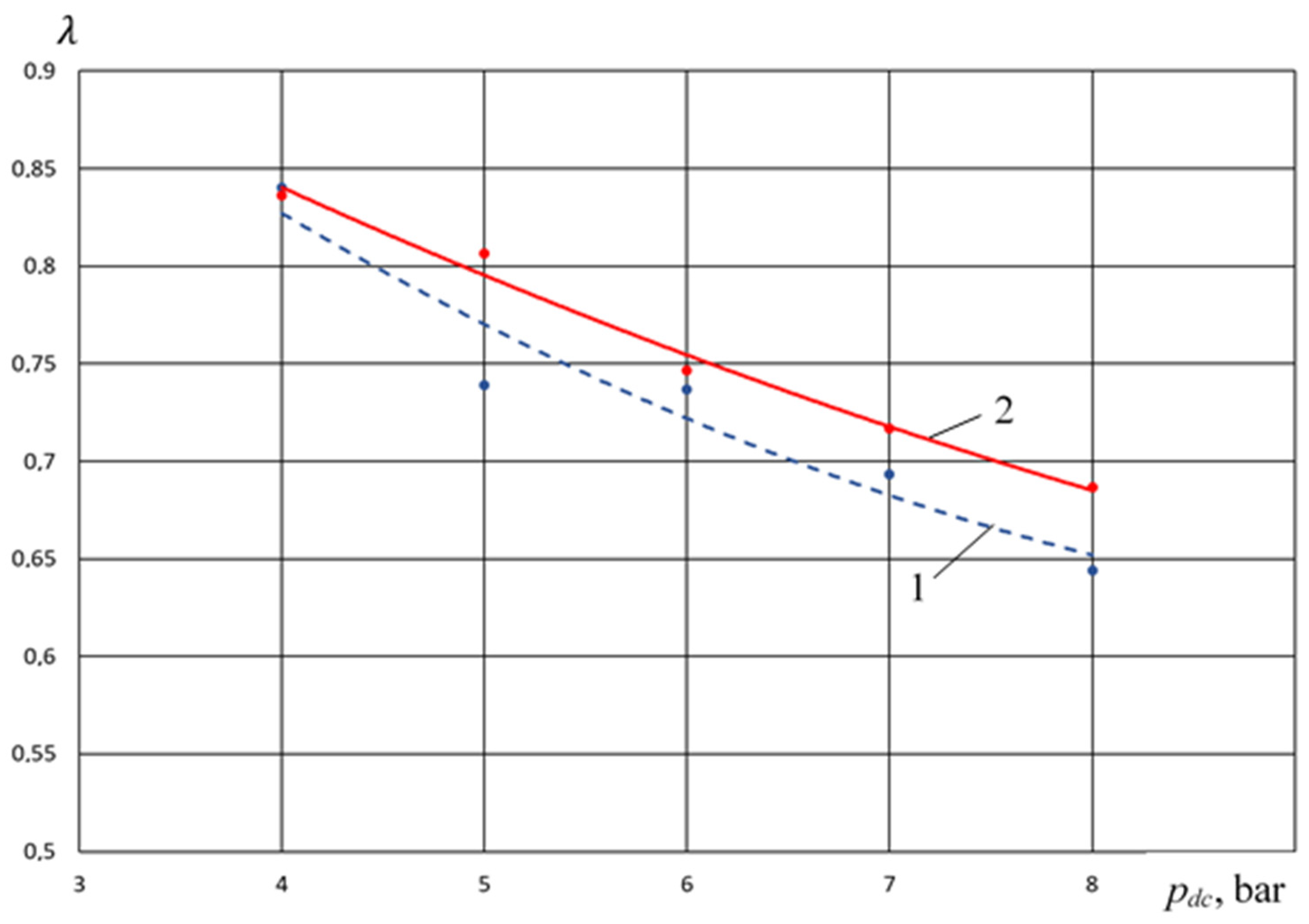
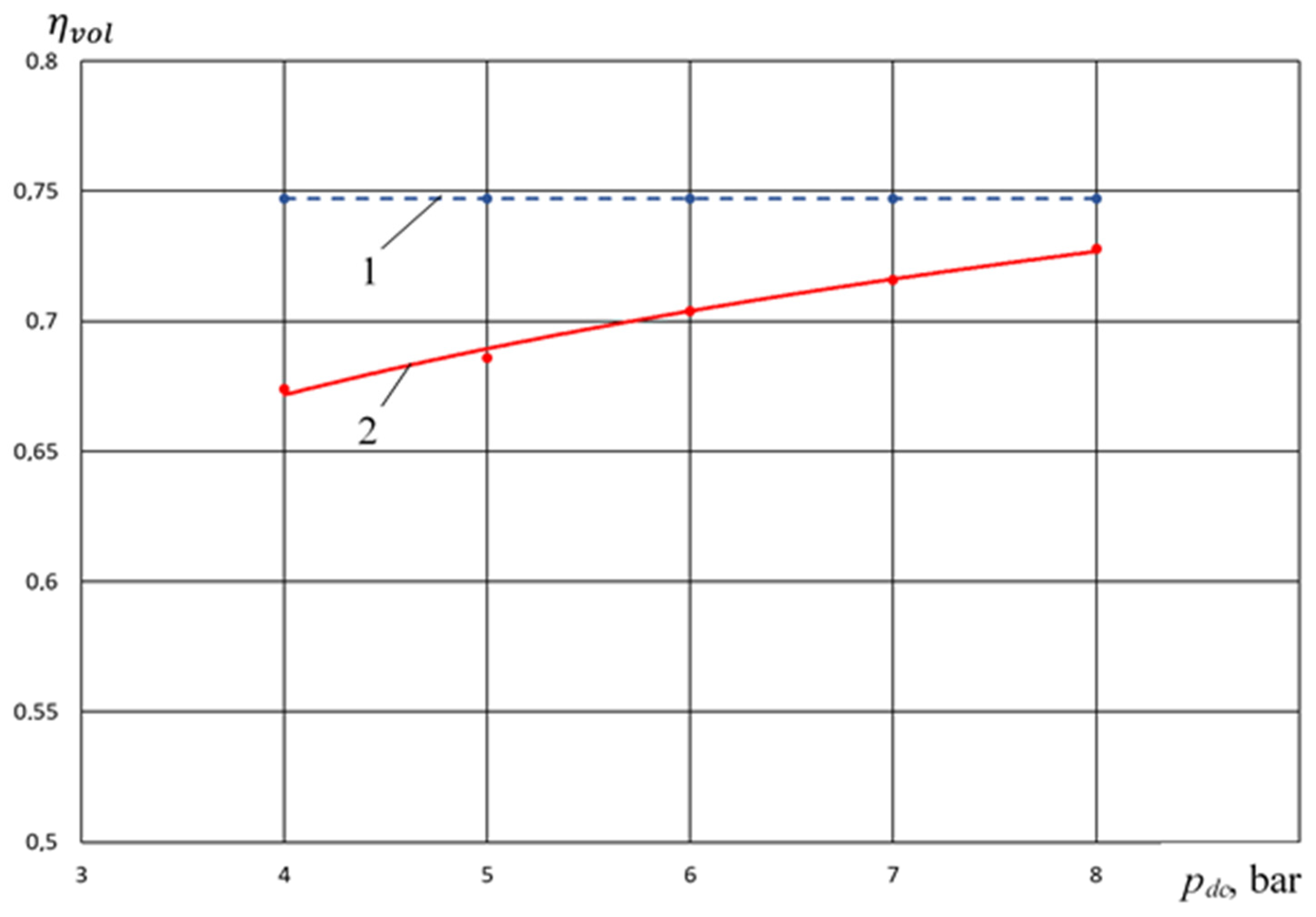
At pdp = 3 bar and nrev = 250 rpm, discharge pressure of the compressor section varied in the range 3 bar ≤ pdc ≤ 7 bar.
-
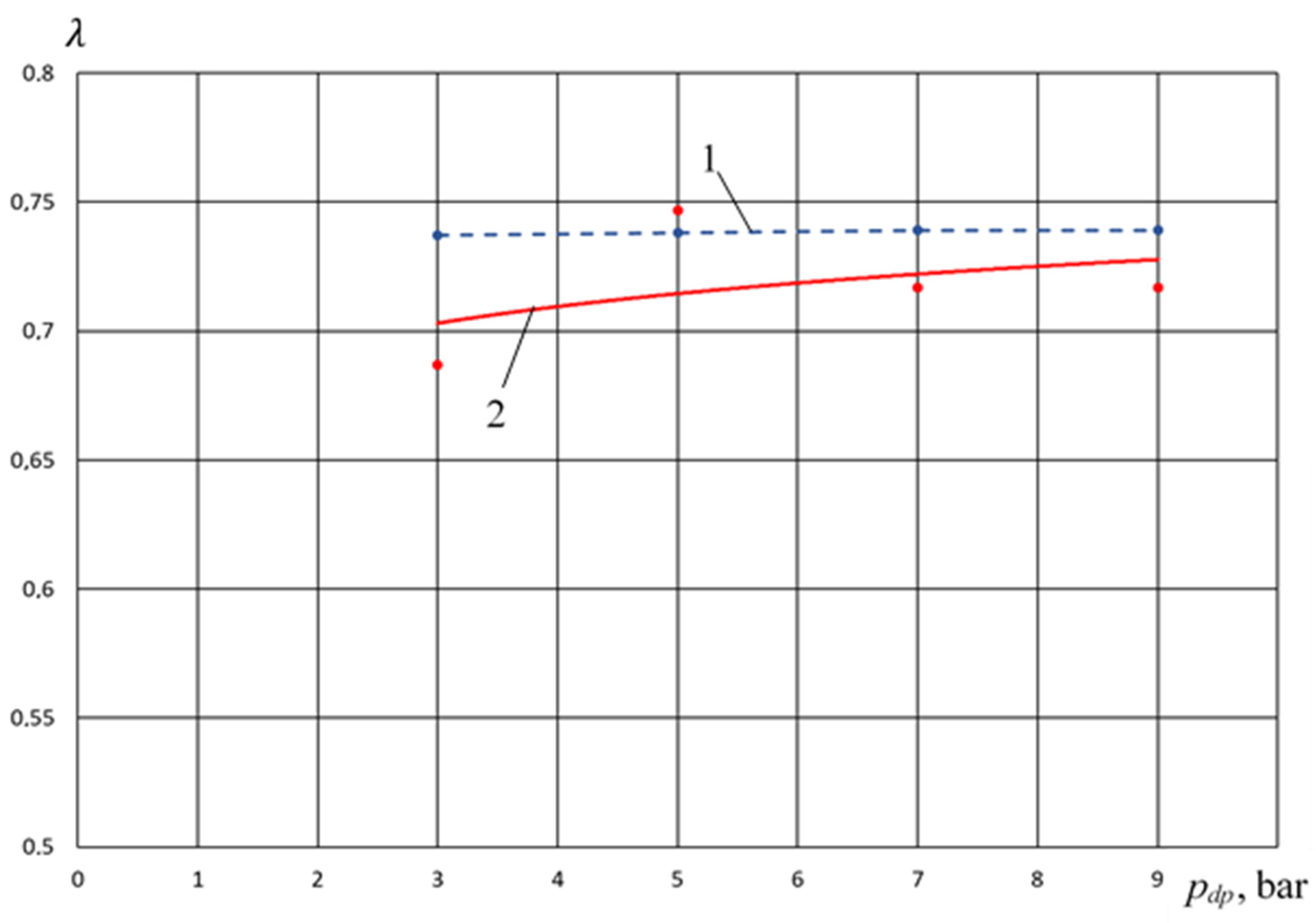
At pdc = 5 bar and nrev = 250 rpm, the pump section discharge pressure varied in the range 2 bar ≤ pdp ≤ 10 bar.
-
At constant discharge pressures in the compressor and pump sections: pdp = 2 bar; pdc = 4 bar angular speed of the crankshaft varied from 250 to 450 rpm.
Water was used as liquid, and air was also used as gas in numerical simulating. In addition, when conducting numerical studies, the following independent parameters were added to the independent operational parameters listed above:
-
Relative dead space value (ad).
-
Radial clearance in the piston seal (δ1).
-
Initial groove seal length (lu0).
The developed mathematical model considers a physical picture of the work processes in the compressor and pump sections of the crosshead-free PHPM.

4.1. Physical Picture of Ongoing Work Processes (Based on the Results of Numerical Analysis)

We consider bottom dead center as a starting point. There is a liquid layer δ ≈ 0.001 m (Figure 18) above the piston that corresponds to the amount of dead space in the compressor section. When the piston moves up to the top dead center, there is a decrease in volume in the compressor and pump sections, which causes an increase in pressure. Considering a high modulus of elasticity of liquid, pressure in the pump cavity increases almost immediately, but it increases rather slowly in the compressor section (Figure 19 and Figure 20).
At φ ≈ 3.4 rad, the pumping process begins in the pump section. Due to the significant pressure difference between the pump and compressor sections, the liquid from the pump section flows into the compressor section and the height of the liquid layer increases. It should be noted that with an increase in the angle of rotation, the length of the groove seal increases (Figure 21) and the pressure drop between the cavities decreases (Figure 19 and Figure 20), leading to a decrease in the instant liquid flow rate from the pump section to the compressor section and the growth rate of the total liquid flow from the pump section to the compressor section (Figure 22).
At the angle of rotation φ ≈ 5.3 rad, the pressure in the compressor section exceeds the pressure in the pump section (Figure 19 and Figure 20), liquid moves into the opposite direction, and the total amount of liquid flowing from the compressor section to the pump section increases (Figure 23). It should be noted that there is a discharge process in the compressor and pump sections this time. When the piston reaches the top dead center, the height of the liquid layer above the piston exceeds the dead volume and all gas from the compressor section is pushed into the discharge line (Figure 24); then, the “pump” stroke starts, and part of the liquid from the compressor cavity enters the discharge line through the discharge valve of the compressor section (Figure 18).
By the end of the discharge process, the height of the liquid layer will be equal to the linear dead volume—0.001 m. It should be noted that the amount of liquid flowing from the compressor section to the pump section (Figure 23) sharply increases at the end of the discharge process. This is due to a sharp increase in the discharge pressure of the compressor section (Figure 19) due to the implementation of the “pump” stroke in the compressor section. When implementing the pump stroke, the increase in pressure is due to an increase in the density of the working liquid tens of times, and dropping liquid is discharged instead of gas.
When the piston moves down, there are reverse expansion processes in the compressor and pump sections of the hybrid power machine. If all the dead space is filled with liquid in the compressor section, the reverse expansion processes in the pump and compressor sections are identical and proceed almost the same, especially if the dead volumes are the same.
If there is compressed gas in the dead space of the compressor section, the reverse expansion will take place at a larger angle of rotation of the crankshaft, and the suction will be in the pump cavity. This will lead to liquid flow into the pump section from the compressor section and thereby will prevent the flow of “fresh” portions of liquid through the suction valve into the pump section reducing volumetric efficiency.
During the suction process, when the nominal suction pressures and pressure losses in the pump and compressor sections are equal, there will be no liquid flow through the groove seal into forward and reverse directions (see Figure 22 and Figure 23). If the pressure loss in the pump section exceeds the pressure loss in the compressor section, the liquid will flow from the compressor section to the pump section (Figure 23, end of the suction process).
If the pressure loss in the compressor section is more than in the pump section, liquid from the pump section through the groove seal enters the compressor section (Figure 22).
Thus, in the suction process, the liquid fills not only the entire space of the working chamber of the pump section but also part of the space of the compressor section.

4.2. Analysis of the Influence of the Main Operational Parameters on the Work Processes of Crosshead-Free PHPM (Based on the Results of Experimental Studies)

Discharge pressure in the pump section pdp (pdc = 0.6 MPa, nrev = 300 rpm)
For PHPM operation with liquid supply from pump section to the compressor section, the liquid removal into the discharge line of the compressor section is typical. If there is increase in the discharge pressure of the pump section, then the amount of discharged liquid increases.
Figure 25 shows that at pdp with 0.3 MPa, there is an intensive removal of liquid ΔVw to the discharge line of the compressor section. This dependence (curve 3) has a parabolic nature (inverted parabola). At pdp = 0.7 MPa, ΔVw is 15 mL/min. This value is less than ΔVw for PHPM with a stepped groove seal (curve 1). Thus, the crosshead-free PHPM in terms of the amount of liquid taken out is an intermediate between the PHPM with a smooth groove seal and the PHPM with a stepped groove seal, and it is closer to the last.
Due to enhanced cooling of the cylinder in the developed new design, as well as the suction and discharge pipes, there is intensive cooling of the entire cylinder–piston group and, in particular, the valve plate as one of the most heated parts.
Experimental results presented in Figure 26 lead to conclusions:
-
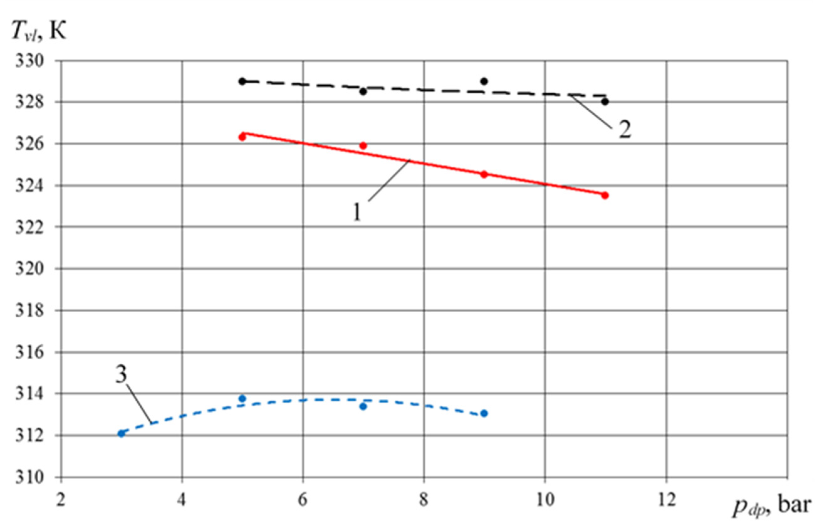
Valve plate temperature has a maximum at pdp = 5 bar–314 K. If pdp increases, Tvl decreases.
-
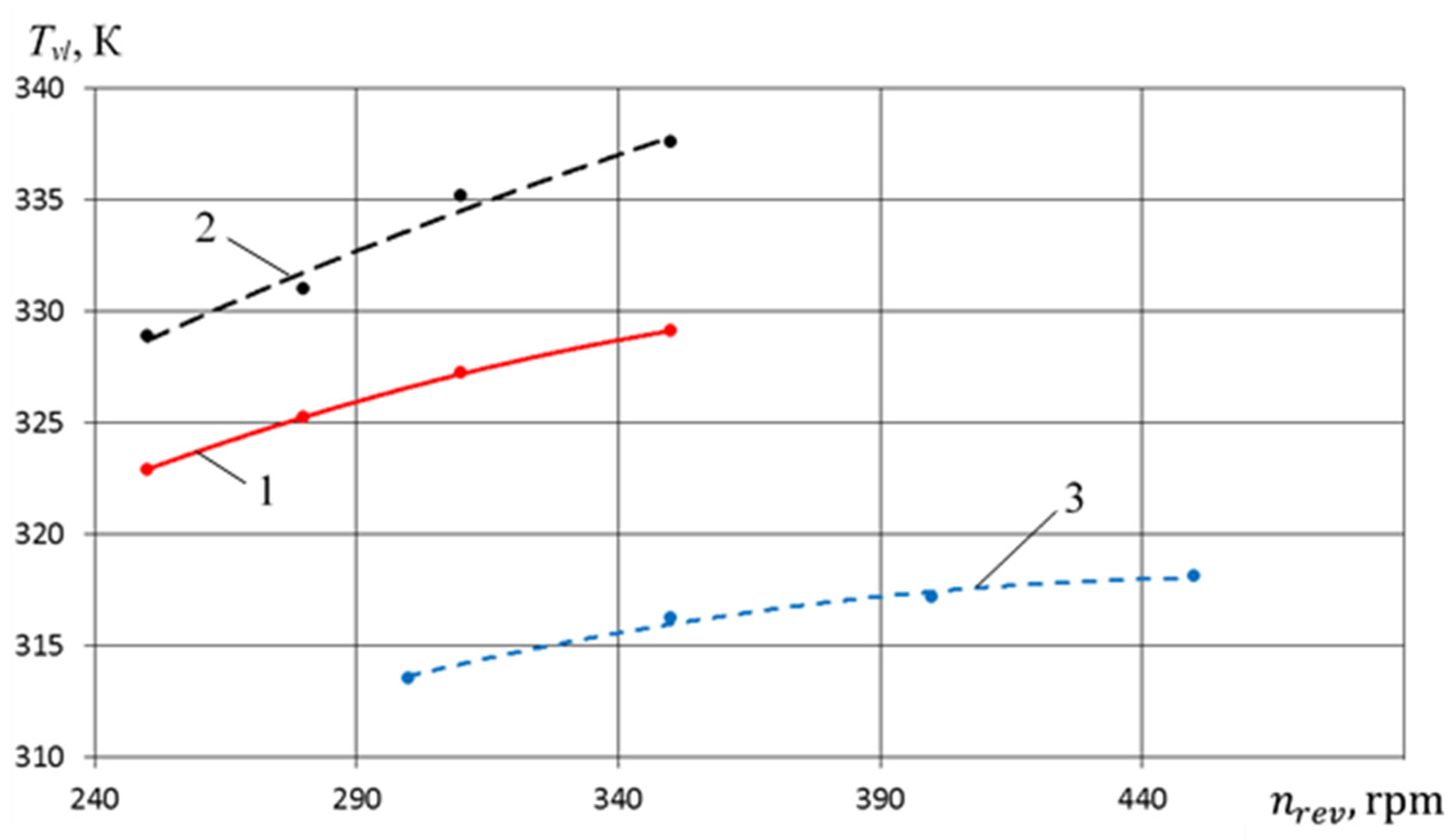
Decreasing Tvl causes an increase in the discharge pressure of the pump section, which is also typical for earlier studies (curves 1 and 2). The most significant decrease Tvl is observed for a PHPM with a stepped groove seal, which is due to a more intensive liquid flow from the pump section to the compressor section.
The temperature of the valve plate of the crosshead-free PHPM is from 10 to 12 K lower than the temperature of the cover of the PHPM with a stepped groove seal, which is a very significant result and fully corresponds to the stated aim
Figure 27 shows the dependence of the temperature of the suction gas on pdp. It should be noted that in this case, as for Tvl, we observe the above trends. For a crosshead-free PHPM, the maximum value of the intake air temperature is observed at pdp = 0.5 MPa. Change in intake gas temperature when changing pdp from 0.3 to 0.9 MPa is about 1 K. The presented results prove that a decrease in temperature of intake air throughout the change pdp amounts to about 8 K, which is a very significant result and leads to an increase in the flow coefficient of the compressor section (Figure 28) and to the following conclusions:
-
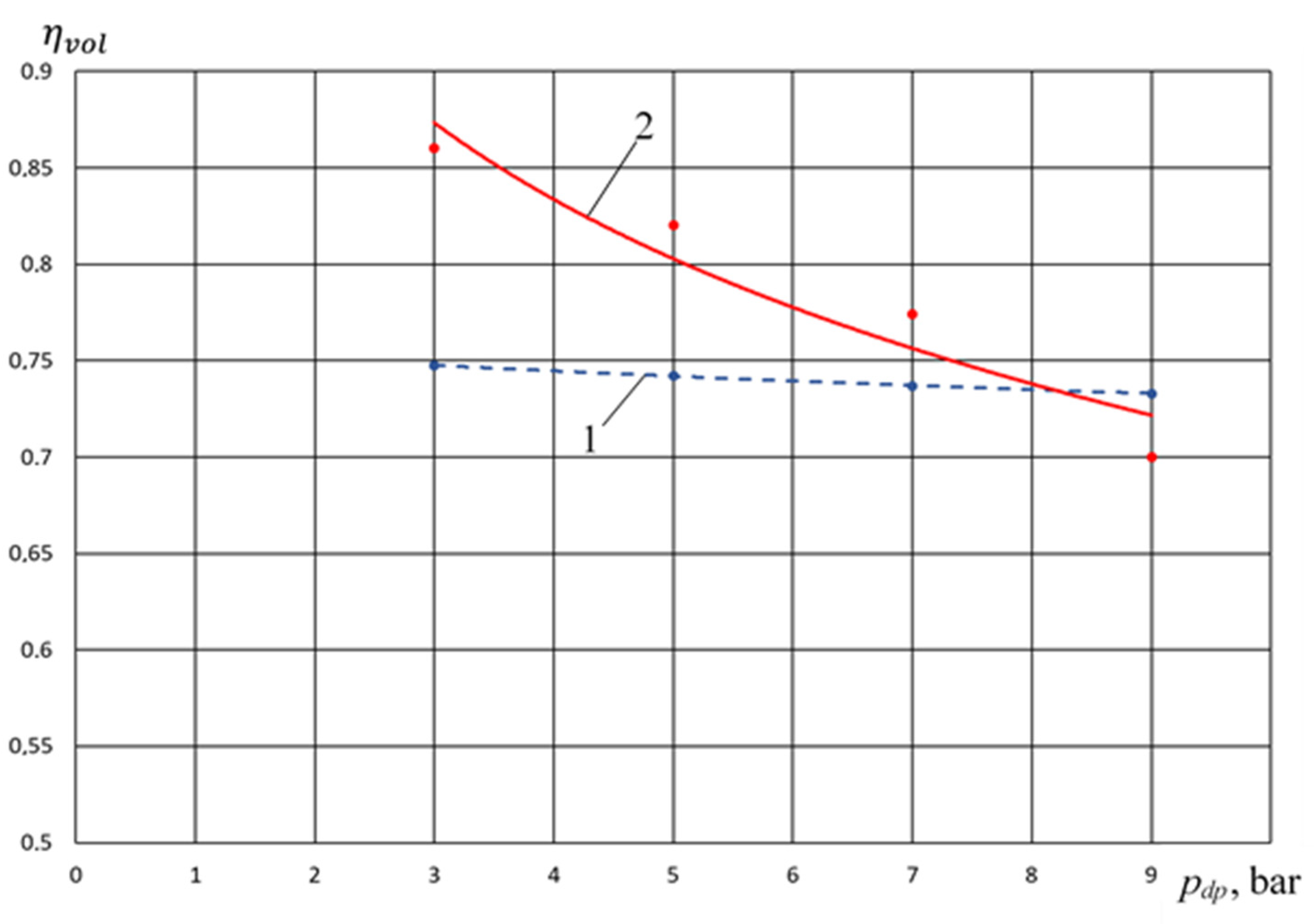
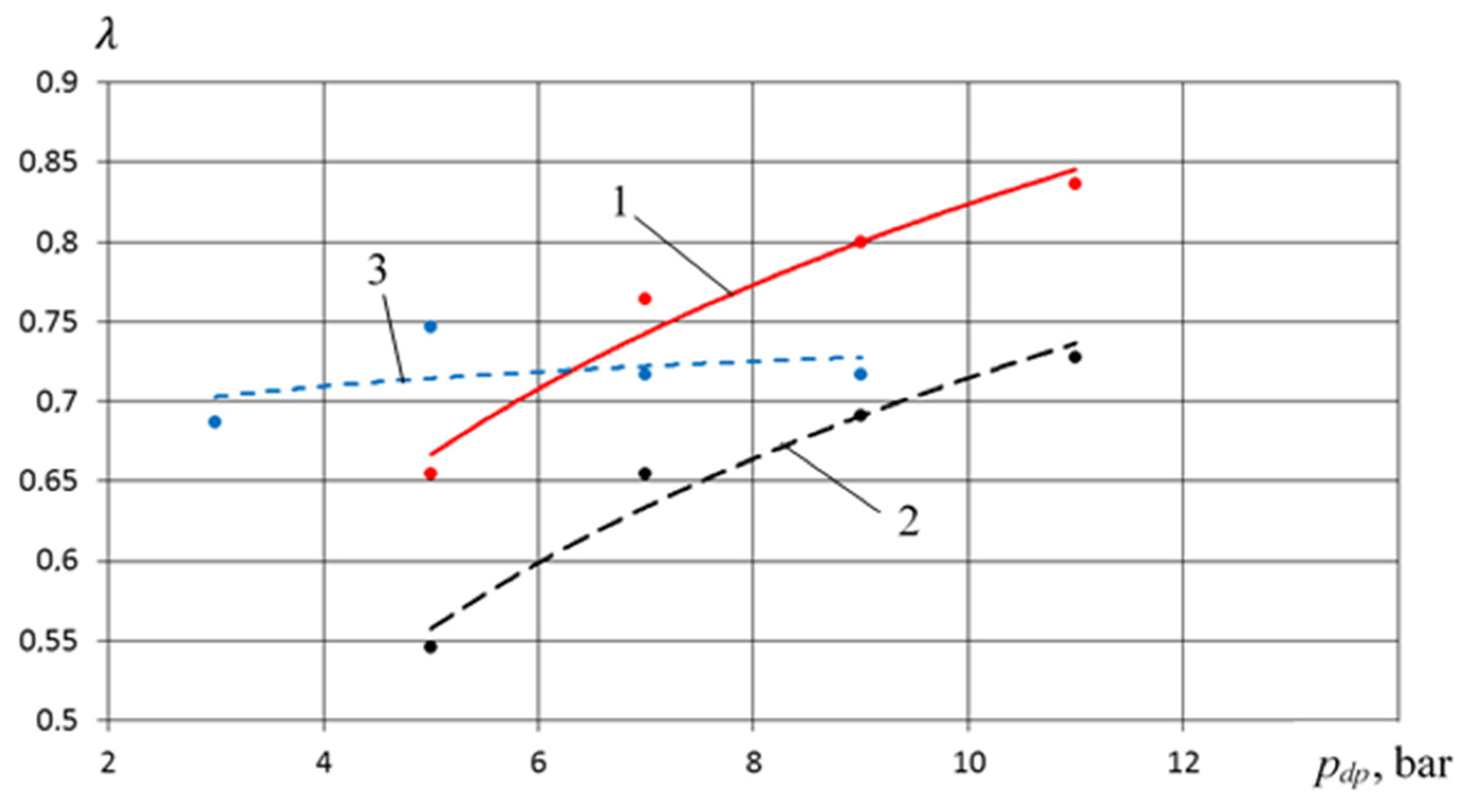
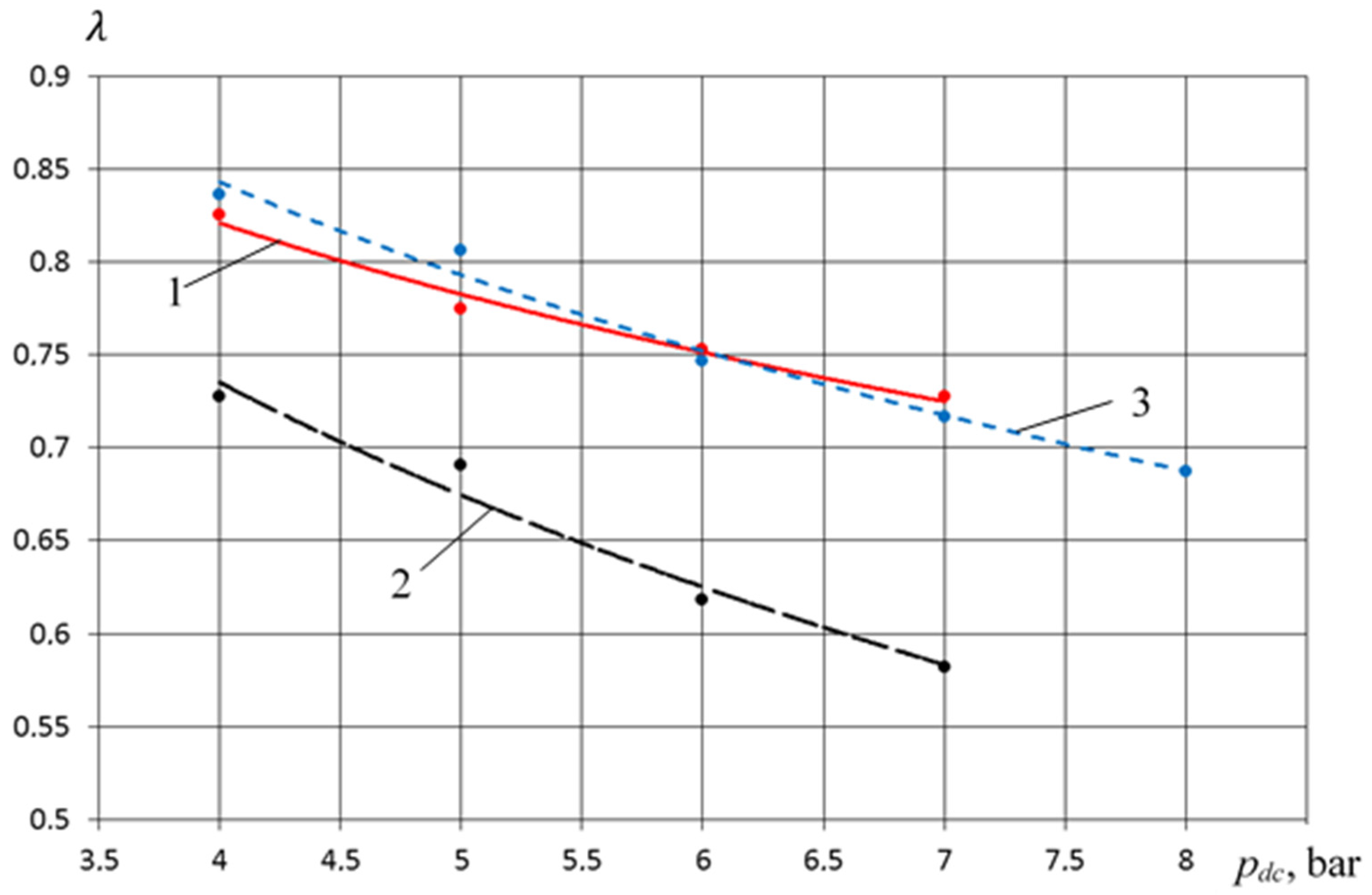
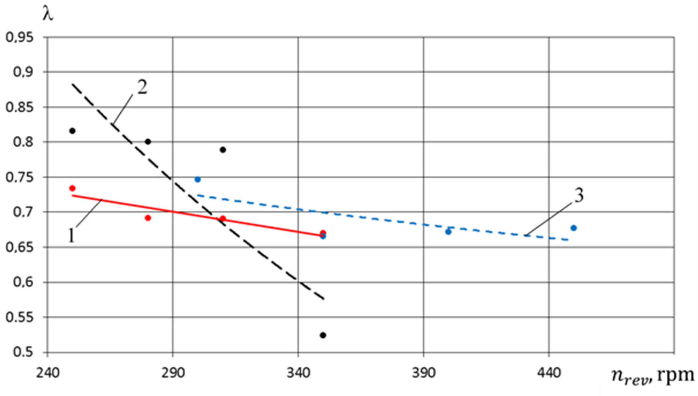
In the range of pressure change 0.3 MPa ≤ pdp ≤ 0.6 MPa, the feed coefficient of the compressor section for the crosshead-free PHPM exceeds the values of the feed coefficients for the PHPM with smooth and stepped groove seals. So, at pdp = 0.5 MPa, the excess feed rate is 0.2 and 0.1 compared with smooth and stepped groove seals, which is, respectively, 27% and 13.5%. Such λ increase is due to λ T , which is a high-temperature coefficient.
-
In the range 0.6 MPa ≤ pdp ≤ 0.9 MPa, the λ feed coefficient for the crosshead-free PHPM exceeds the values of the feed coefficients for the PHPM with smooth groove seals, but λ is lower for the PHPM with stepped groove seals. This is due to the fact that in the PHPM with a stepped groove seal, the amount of incoming liquid from the pump section to the compressor is the maximum among the options considered. This leads to a decrease in dead space and an increase in λ 0 volumetric coefficient and λ .
Increasing pdp, the volumetric efficiency of the pump section decreases (Figure 29). This decrease is typical for all types of positive displacement pumps. Decreasing η v o l is significant and amounts to Δ η v o l = 0.15 when increasing pdp from 0.3 to 0.9 MPa. It should be noted that this dependence is close to linear, and the angle of inclination for all three of the presented dependences is approximately the same. Crosshead-free PHPM η v o l exceeds the volumetric efficiency of PHPM with stepped and smooth groove seals for 5–10%, respectively.
Discharge pressure in the compressor section pdc (pdp = 0.3 MPa, nrev = 300 rpm)
Increasing pdc, the amount of liquid carried into the discharge line of the compressor section is reduced (Figure 30).
In terms of the discharged liquid amount, the crosshead-free PHPM is close to the PHPM with a smooth groove seal and at pdc = 0.7 MPa, the amount of liquid they carry is the same and equal to 2 mL/min. It should be noted that the amount of liquid to be removed from the PHPM with a stepped groove seal is 5–10 times higher than the amount of liquid to be removed from the above-mentioned devices.
Decreasing the amount of liquid leads to increase in temperature of the valve plate (Figure 31) and temperature of the intake gas (Figure 32).
Dependences Tvl and Tscc have a linear nature due to pdc. The presented results lead to the following conclusions:
-
The temperature of the valve plate for the crosshead-free PHPM is 10 K and 15 K, respectively; it is lower than that of the PHPM with a stepped and smooth groove seal.
-
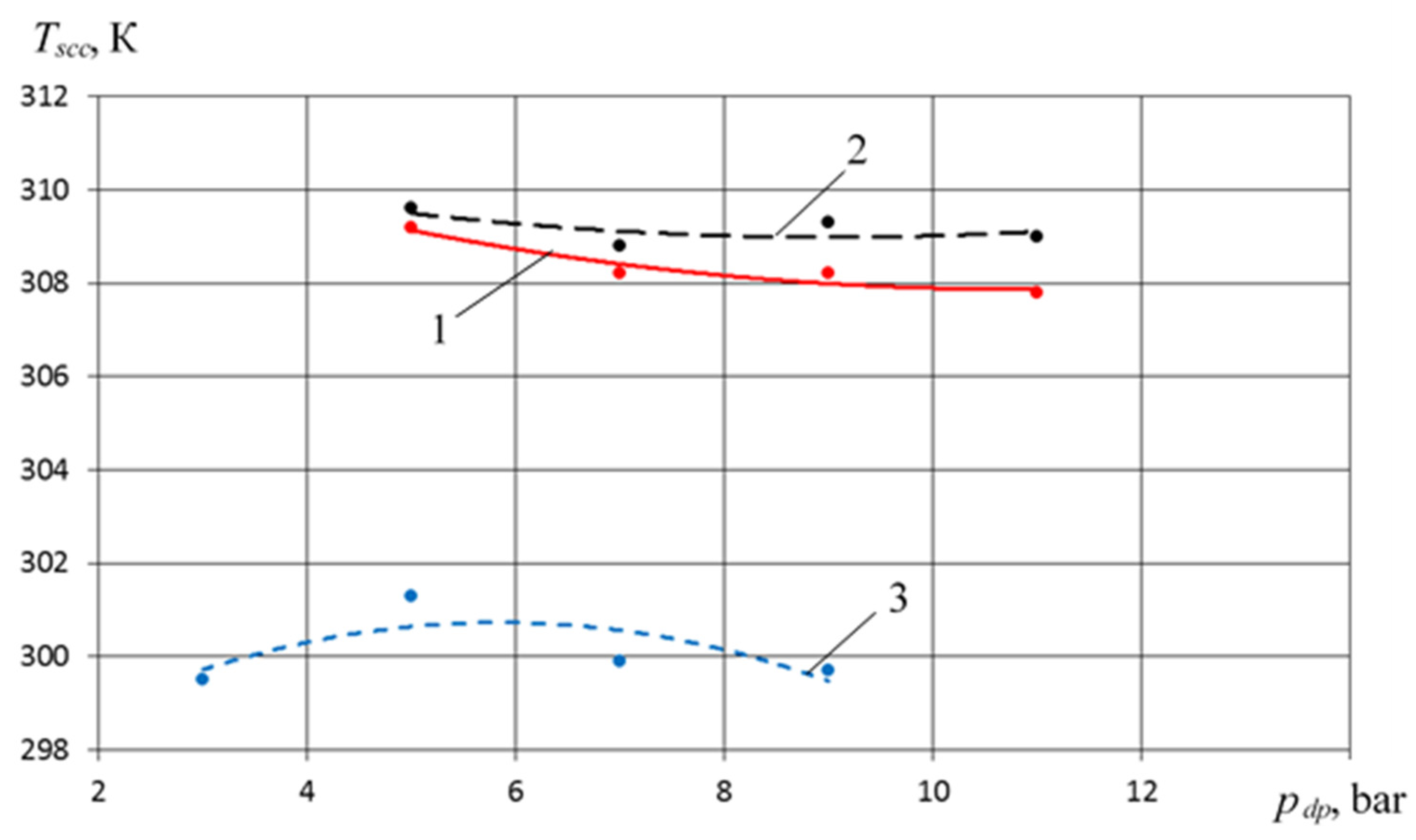
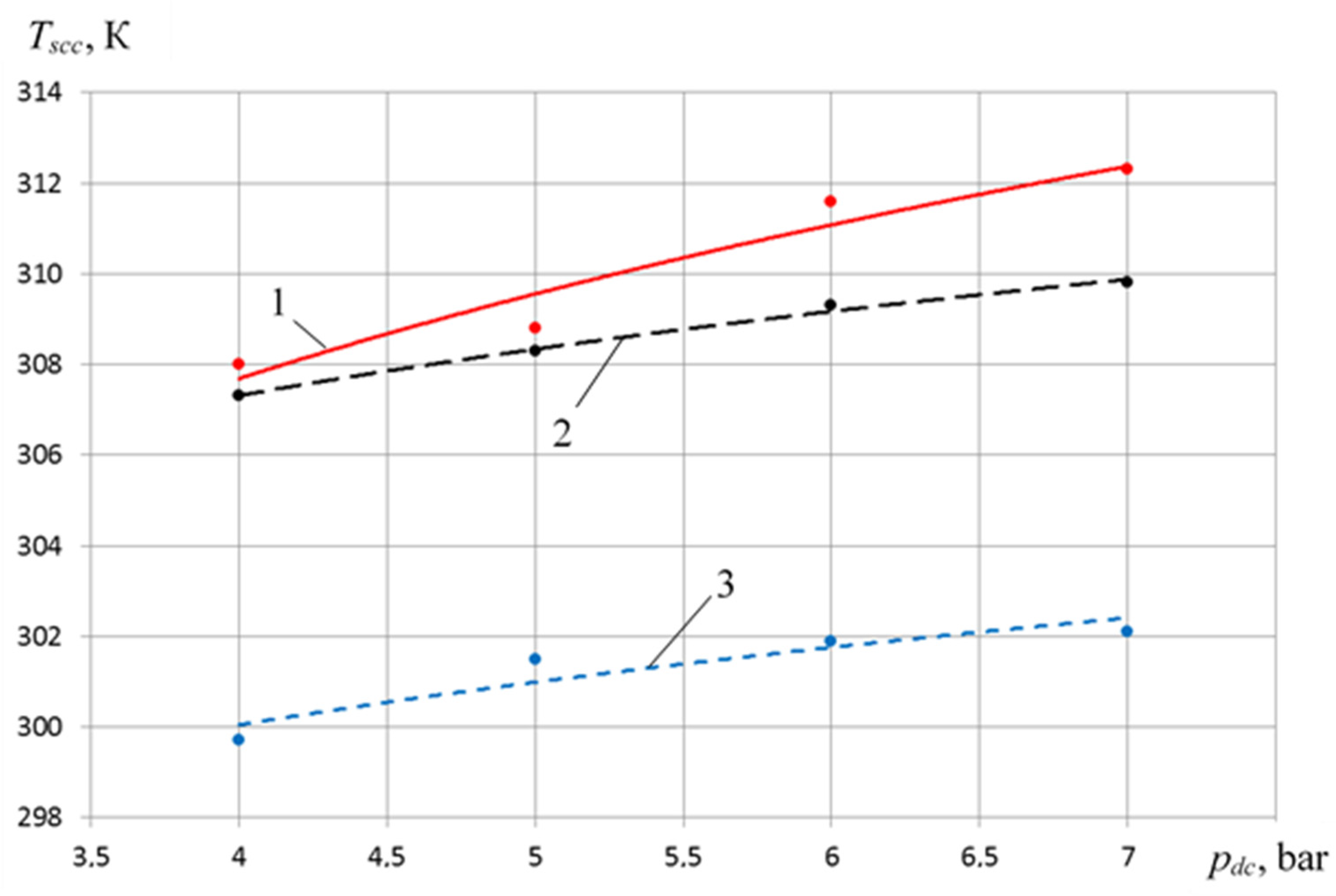
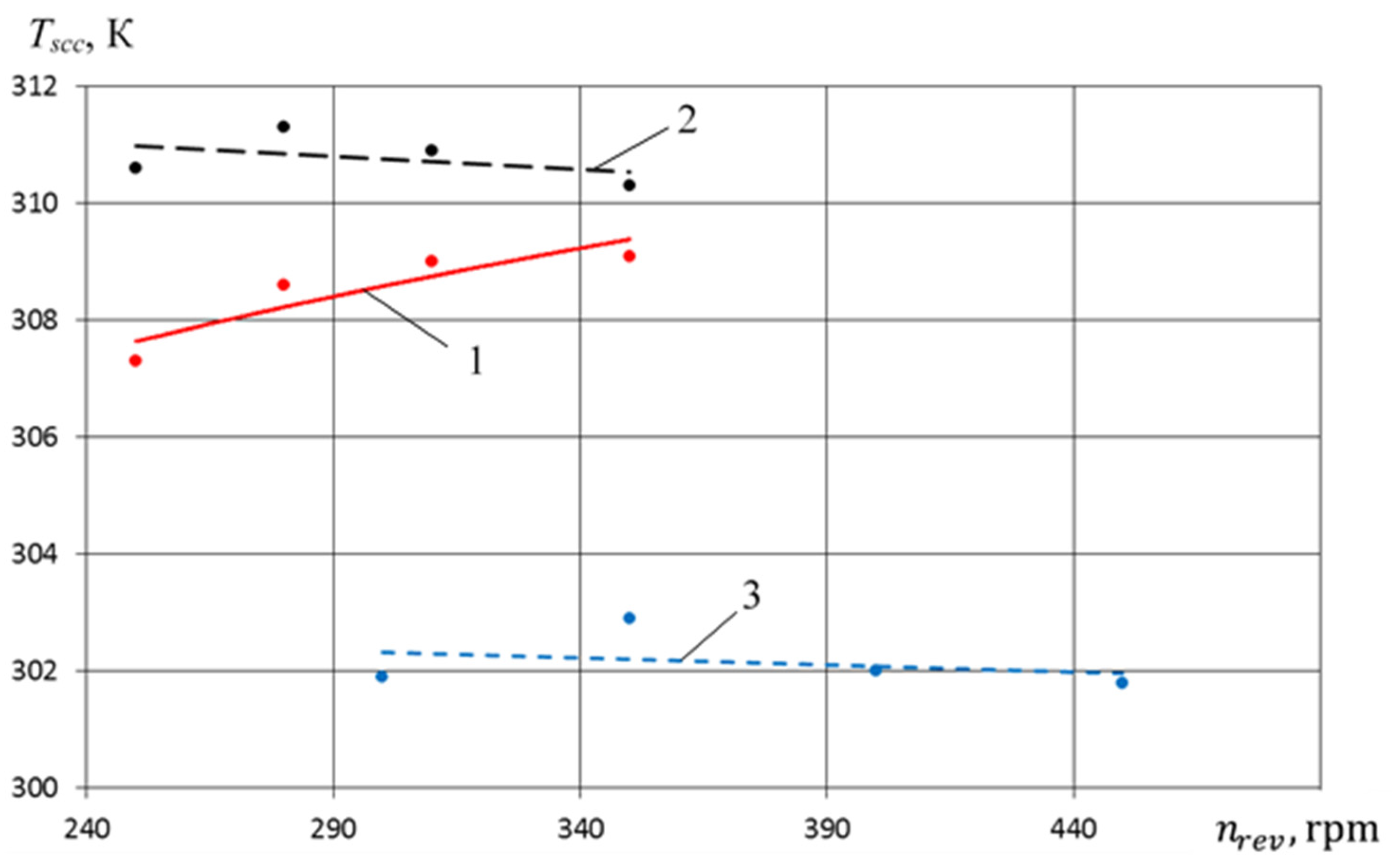
Intake gas temperature Tscc of the crosshead-free PHPM is lower by 6 K and 8 K, respectively, than PHPM with a stepped and smooth groove seal.
Increasing the temperature of the intake gas and an increase in the dead space by reducing the liquid flow from the pump section to the compressor leads to a decrease in the temperature coefficient λ T and volumetric coefficient λ 0 , and therefore the entire feed rate λ . Crosshead-free PHPM value λ is equal with λ for PHPM with a stepped groove seal (Figure 33) and exceeds λ for PHPM with a smooth groove seal from 10 to 20%.
With increasing pdc, there is an increase in volumetric efficiency (Figure 34). It should be noted that η v o l for crosshead-free PHPM exceeds η v o l for PHPM with a stepped and smooth groove seal from 2 to 4%.
Crank angular velocity (pdc = 0.6 MPa, pdp = 0.3 MPa)
With an increase in the crank angular velocity, the amount of discharged liquid per unit time decreases for a crosshead-free PHPM (Figure 35), and it increases for PHPM with smooth and stepped groove seals.
The amount of liquid to be discharged into the discharge line of the compressor section for a crosshead-free PHPM is practically equal to the quantity of liquid to be discharged to the PHPM with a smooth groove seal and is significantly less ΔVw for PHPM with stepped groove seals. If there is an increase in η v o l , then the valve plate temperature increases for all considered PHPM options.
It should be noted that its values from 314 to 318 K and its values from 12.5 to 22 K are lower than the temperature of the valve plate for the PHPM with smooth and stepped groove seals, respectively (Figure 36).
If there is an increase in nrev, the temperature of the intake gas decreases both for the crosshead-free PHPM and for the PHPM with a smooth groove seal. For the PHPM with stepped groove seals, an inverse tendency is typical (Figure 37). It should be noted that for a crosshead-free PHPM, the temperature of the intake air is from 8 to 10 K lower than all the options considered, which is very important and leads to an increase in productivity and indicator efficiency.
If there is increase in crank angular velocity, λ T and λ p values decrease, as well as λ 0 , due to decrease in the amount of liquid coming from the pump section to the compressor. This leads to a decrease in the flow rate of the compressor section λ (Figure 38). It should be noted that in the range of the investigated crank angular velocity, the feed coefficient for the compressor section of the crosshead-free PHPM exceeds λ for PHPM with smooth and stepped groove seals from 5 to 10%.
If there is increase in the crank angular velocity, then the amount of under filling of the working chamber of the pump section increases due to friction forces and inertial pressure losses, which leads to a decrease in the volumetric efficiency of the pump section (Figure 39).
It should be noted that with nrev, the increase of λ for the crosshead-free PHPM decreases less—less than 5%, unlike λ for PHPM with smooth and stepped groove seals. In addition, it is essential that λ for the crosshead-free PHPM significantly exceeds nrev (more than 20%) for other options under consideration.

5. Conclusions

(1)
Analysis of the advantages and disadvantages of existing PHPM constructions helped to develop a new design of crosshead-free PHPM, which is protected by a Patent for Invention of the Russian Federation.
(2)
Based on the fundamental laws of energy, mass, and motion conservation, after verification and adoption of a system of simplifying assumptions, a mathematical model of a crosshead-free PHPM with the primary liquid flow from the pump section to the compressor section has been developed, which includes a mathematical model of the compressor section, operating both in compressor mode and in pump mode, a mathematical model of the pump section, and a mathematical model of groove seals. The mathematical model determines the main integral characteristics of the compressor and pump sections: compressor delivery ratio, indicator efficiency, volumetric efficiency, mass of liquid removed from the compressor section per cycle, etc.
(3)
The developed mathematical model considers the physical picture of the ongoing work processes in the compressor and pump sections, as well as in the groove seals of the crosshead-free PHPM, which include:
-
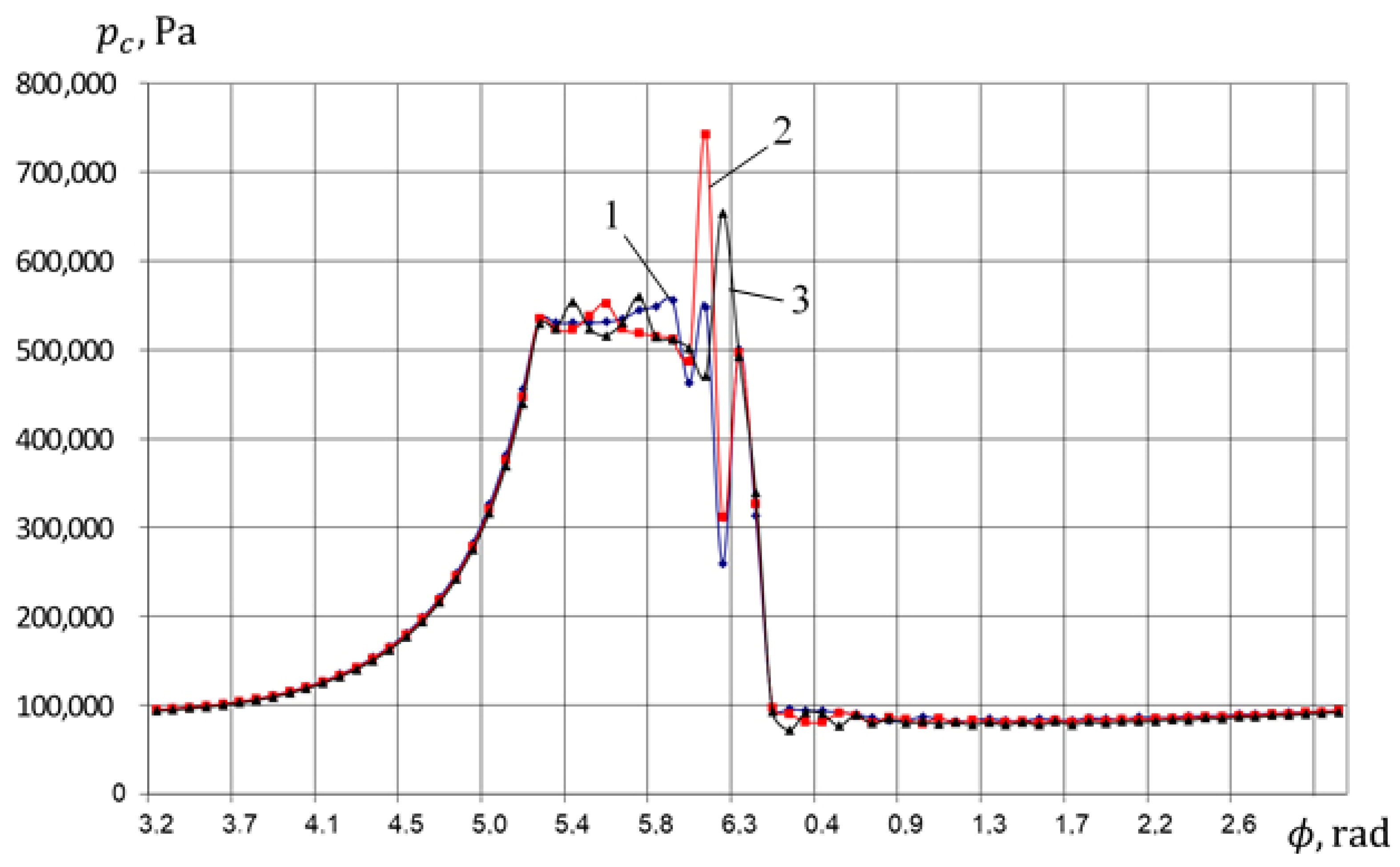
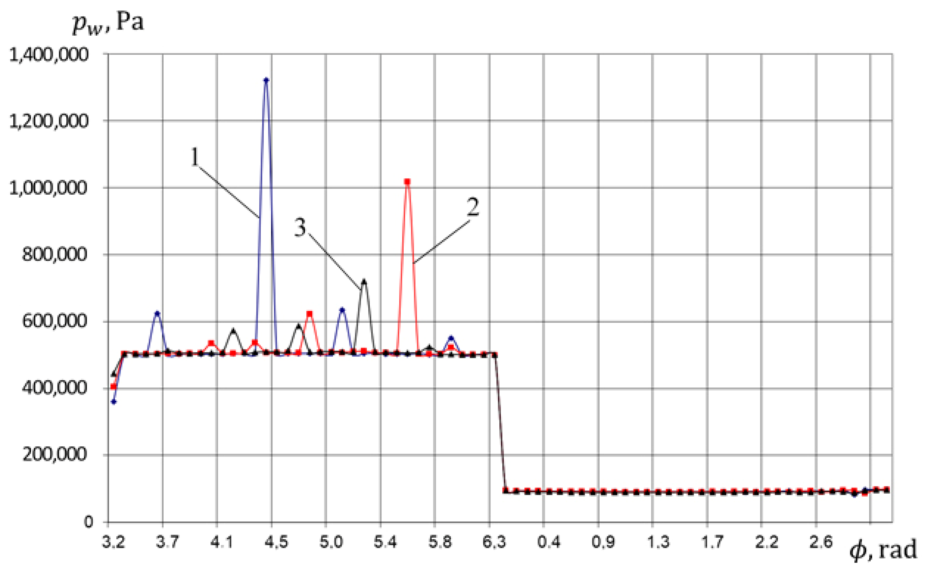
Changes in thermodynamic parameters in the compressor and pump sections in terms of crankshaft angle;
-
Changes in the mass of liquid in the compressor section by the crankshaft angle;
-
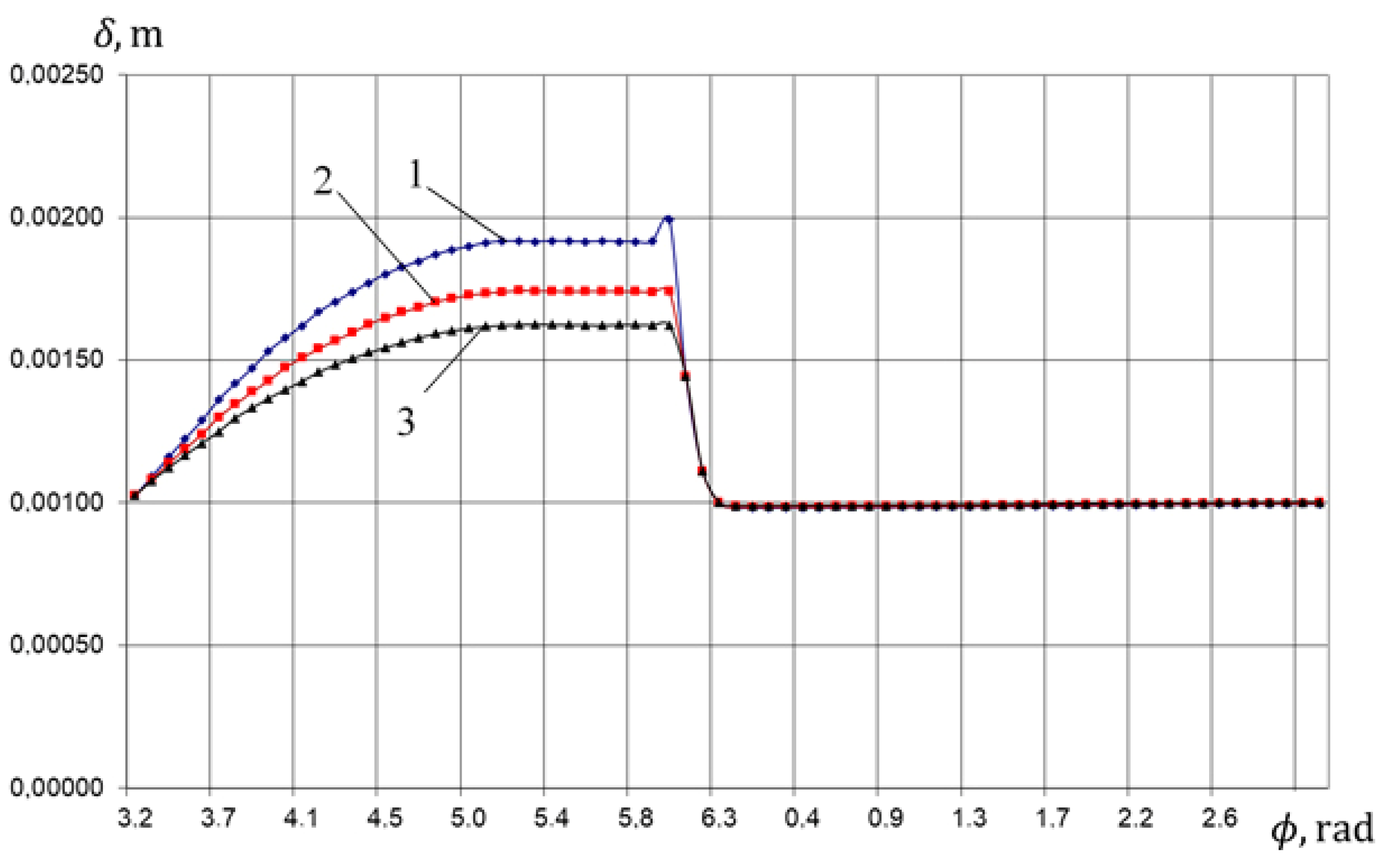
The current height of the liquid layer above the piston in the compressor section according to the crankshaft angle;
-
Implementation of the “pumping stroke” in the compressor section determiming the pressure and flow rate of the liquid in the compressor discharge line.
(4)
Based on the proposed new design of the crosshead-free PHPM, a prototype was developed, and an experimental stand equipped with modern measuring equipment was created. Experimental studies proved the operability of the created prototype in the range of operational parameters; they confirmed the operability of the developed mathematical model with primary liquid flow from the pump section to the compressor section. The verification of the mathematical model was carried out at different discharge pressures of the compressor and pump sections. The comparison was completed using indicator diagrams, feed rate, volumetric efficiency and the volume of liquid removed to the compressor discharge line per cycle. The maximum discrepancy in the instantaneous pressure was observed in the process of injection both in the pump section and in the compressor section, and it was from 10 to 15%. The discrepancy in integral characteristics was within 5–10%. The developed mathematical model qualitatively and quantitatively describes real physical processes and is true to life.
(5)
As a result of the experimental and theoretical studies, it was established:
-
Temperature of the valve plate of the crosshead-free PHPM is from 10 to 15 K less than that of the crosshead PHPM with smooth and step-like groove;
-
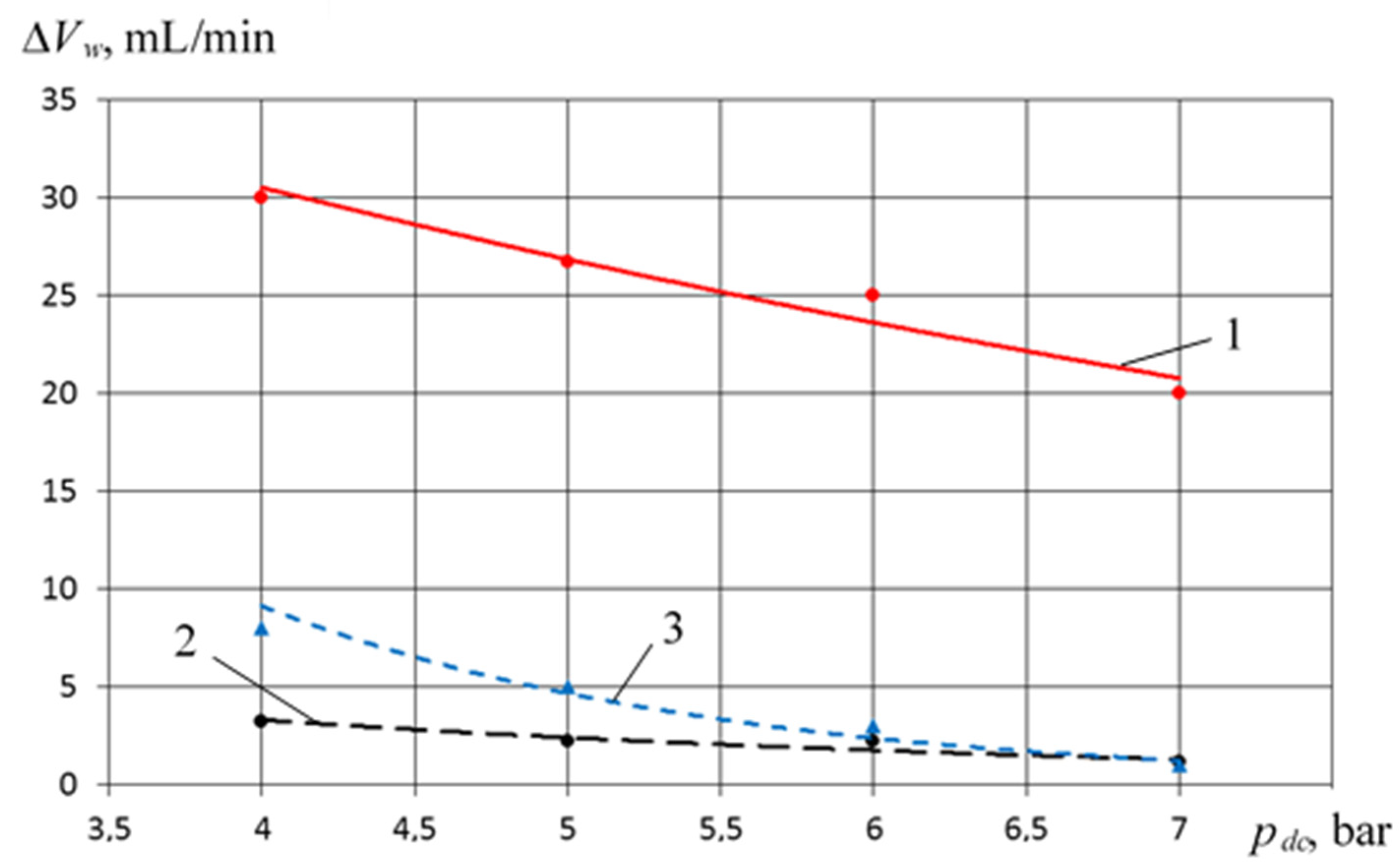
Due to more intensive cooling of the cylinder–piston group in the crosshead-free PHPM, a decrease in the temperature of the suction gas by 6–8 K is observed in the entire range of the studied parameters as compared to the crosshead PHPM with smooth and step-like groove;
-
Due to more intensive cooling of the suction gas, there is an increase in the feed coefficient and indicator efficiency of the compressor section by 3–5% on average, and in some cases, it is higher if compared with analogs;
-
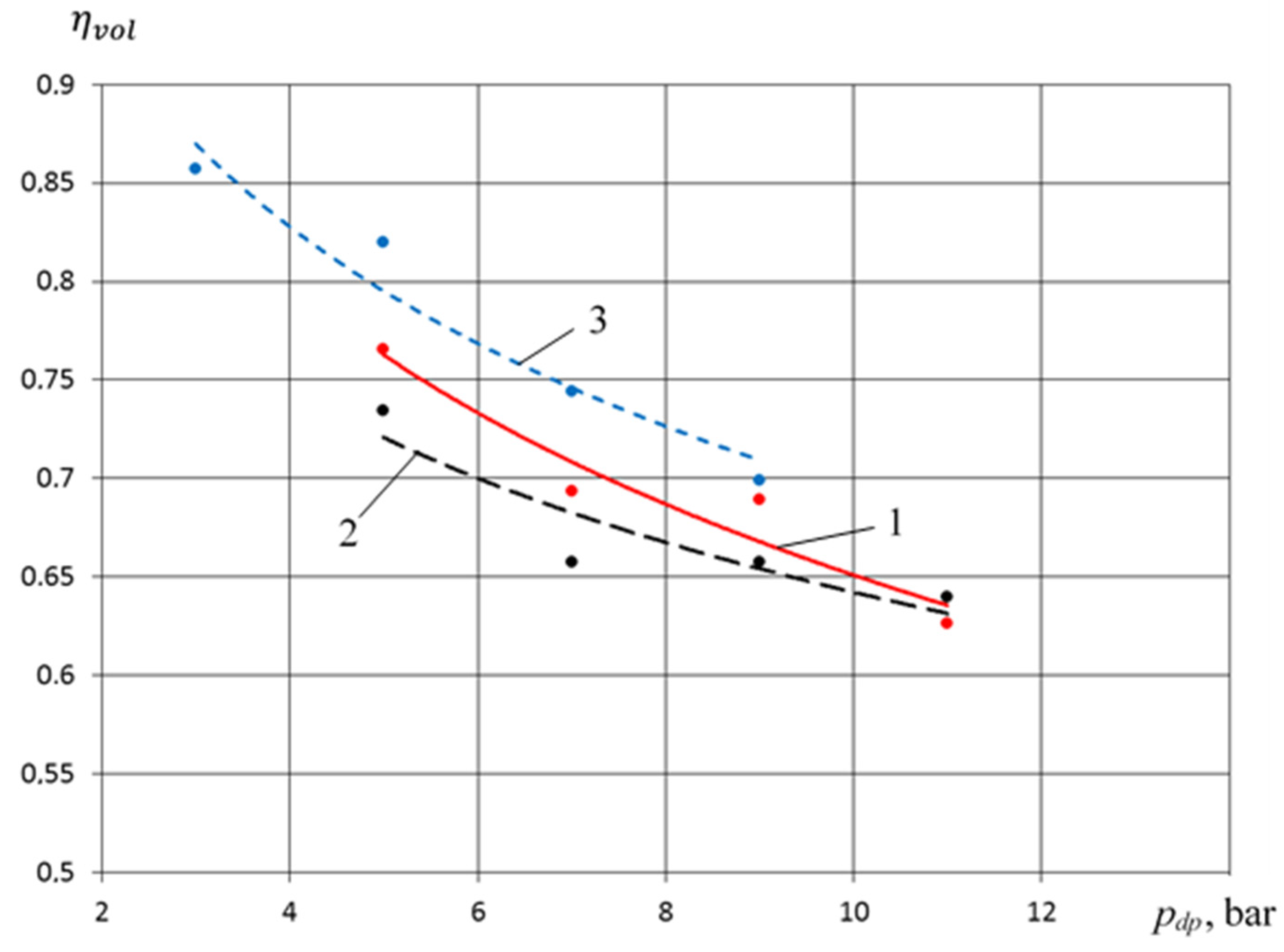
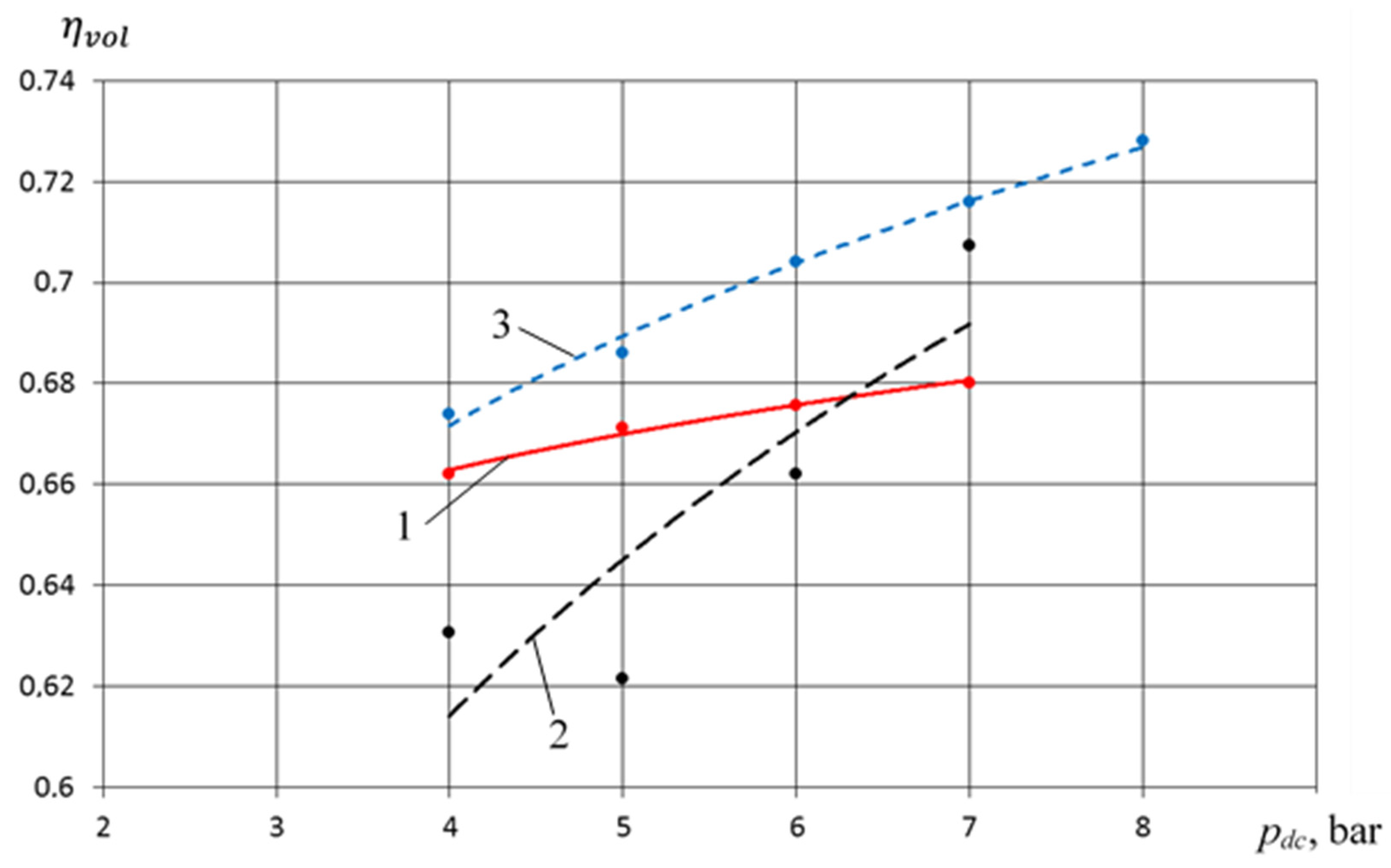
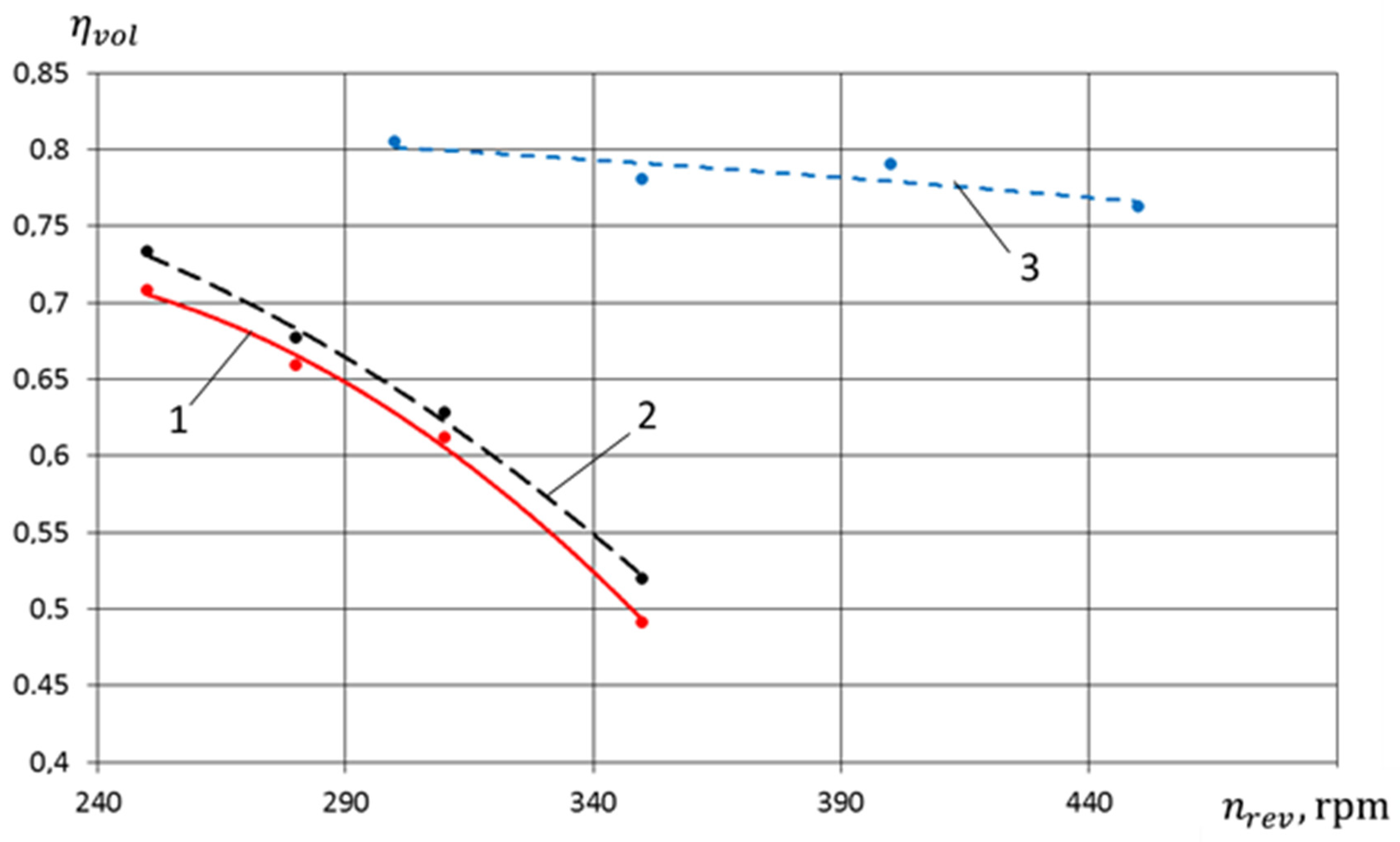
Due to the design features of the crosshead-free PHPM, there is an increase in volumetric efficiency of the pump section by 5–10% compared to the studied analogs;
-
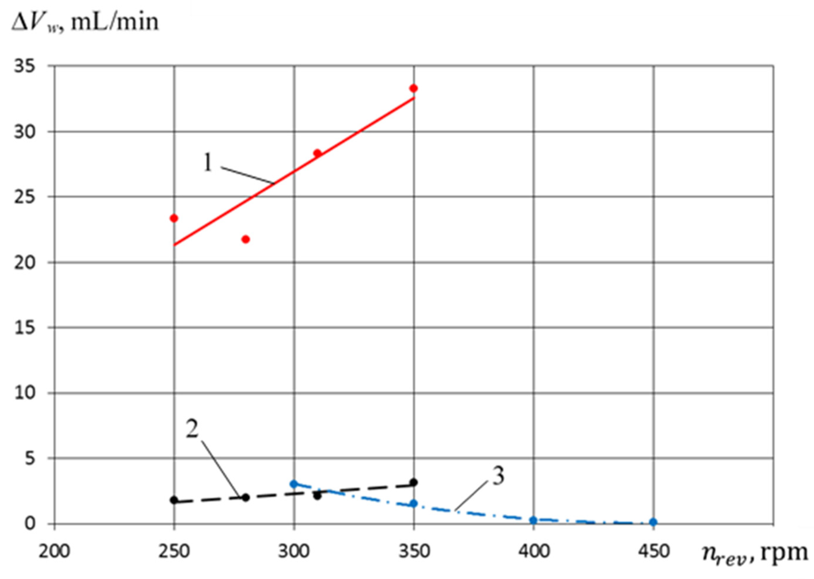
The liquid carryover in the crosshead-free PHPM from the compressor section into the discharge line is at the level of the liquid carryover in the crosshead PHPM with a smooth groove and significantly less than liquid carryover in the crosshead PHPM with a step-like groove. So, it is possible to reduce energy costs for separating liquid from the compressed gas.

Author Contributions

Conceptualization, V.S. (Viktor Shcherba), E.N., E.P. and A.-K.T.; methodology, V.S. (Viktor Shcherba) and E.N.; software, E.P.; validation, V.S. (Viktor Shcherba) and E.P.; formal analysis, V.S. (Viktor Shcherba); investigation, V.S. (Viktor Shcherba); writing—original draft preparation, V.S. (Viktor Shcherba); writing—review and editing, V.S. (Viktor Shcherba), E.P. and E.N.; visualization, E.P., E.N. and A.-K.T.; supervision, V.S. (Viktor Shcherba); project administration, V.S. (Viktor Shcherba); funding acquisition, V.S. (Viktor Shcherba) and V.S. (Viktor Shalay). All authors have read and agreed to the published version of the manuscript.

Funding

This research did not receive any specific grant from funding agencies in the public, commercial, or not-for-profit sectors.

Conflicts of Interest

The authors declare no conflict of interest.

Nomenclature

The nomenclature of the paper is shown below:
pcgas pressure in the compressor section;
Tcgas temperature in the compressor section;
Vcgas volume in the compressor section;
Mcmass of gas in the compressor section;
pwliquid pressure in the pump section;
pscwliquid pressure in the beginning of suction into the pump section;
Twliquid temperature in the pump section;
T ¯ a v t averaged integral temperature of the working chamber surface in the compressor section;
Vwliquid volume in the pump section;
V h working volume of the compressor section;
p, V, T, Mactual thermodynamic parameters in the working chamber of the compressor section-pressure, volume, temperature, and mass, respectively;
Mwliquid mass in the pump section;
Rgas constant;
Ewliquid elastic modulus;
kadiabatic index of the compressible gas;
Uinternal energy of the compressible gas;
Uctotal internal energy of the compressible gas;
dQcelementary amount of heat supplied to the gas;
dMnielementary attachable gas mass;
dMoielementary detachable gas mass;
υ p instantaneous speed of piston;
λtratio of the piston stroke to twice the length of the rod;
ω crank angular velocity;
φcrank angle;
τprocess life;
Cvspecific isochoric heat capacity;
F p piston area in the compressor section;
i n i specific enthalpy of the attached gas mass;
T n i temperature of the attached gas;
C p i specific isochoric heat capacity of the attached gas;
N1, N2number of attached and detachable gas mass;
i 0 specific enthalpy of the detached gas;
ρ w liquid density;
N4, N5number of attached and detachable liquid mass;
msprreduced valve closure mass in the compressor section;
hcdegree of valve closure in the compressor section;
i = 1 N 3 = 4 F i K sum of effective forces to valve closure in the compressor section;
Fggas force;
Fsprcelastic force of the valve spring in the compressor section;
Ffrfriction force of the valve in the compressor section;
Fclcurrent side surface of the cylinder in the compressor section;
ggravitational acceleration;
Shfull piston stroke;
dVkinelementary change of compressor section volume during time derived from kinematics of drive mechanism;
F c o v heat-transfer area between gas and fluid liner;
pcddischarge pressure in the compressor section;
S current piston stroke;
δ liquid layer thickness over the piston;
Fvlvalve body area;
α ¯ T averaged heat-transfer coefficient in the working chamber of the compressor section;
T ¯ w averaged liquid temperature over the piston;
T ( F ) c o v , T c l ( F ) thermal fields along valve body cover and fluid liner;
M w 0 , V w 0 mass and volume of liquid in the beginning of liquid discharge process;
pwdpressure of liquid in the beginning of discharge process;
V w , M w current volume and mass of liquid in the working chamber;
dMwni, dMw0ielementary masses of attached and detached liquid;
dMwelementary change of liquid mass;
Vdcdead volume in the working chamber of the compressor section;
α g r w , f g r flow coefficient during liquid flow and valve cross-sectional area;
pipressure in the control volume where liquid flows;
Twcurrent temperature of the working liquid;
Vdwdead volume in the pump section;
d2, d1inner and outer diameter of the piston;
V s c w liquid volume in the beginning of compression process;
M s c w actuation liquid mass in the beginning of compression process;
dMniwi-th liquid leakage;
dM0iwi-th liquid leak;
w1liquid velocity in I–I cross-section matching with piston head;
w2liquid velocity in II–II cross-section located behind the discharge valve;
Δ h T 1 2 friction losses derived by performing technical work between the selected sections;
Δ h 1 2 friction losses (along the length and local losses);
Δ h friction losses;
Δ h ζ friction losses for local losses;
α angle between the cylinder vertical and axis;
m d r w derived mass of the valve closure of the self-acting valve of the pump section;
hwcurrent degree of the valve closure of the self-acting valve of the pump section;
i = 1 N 6 F w i sum of forces acting on closures of self-acting valves during “pump stroke” into the compressor section;
i = 1 N 6 F i w sum of forces acting on valve closure of the self-acting valve;
λ f r friction coefficient along the length;
λactual volumetric efficiency;
S d linear dead space in the compressor section;
S D w linear dead space in the pump section;
S w current piston stroke in the pump section;
f 2 discharge pipe area;
f g r current discharge valve gap area;
dpdiameter of the discharge valve;
dvldiameter of the valve closure;
ρ s c density of the suction gas;
V h c piston displacement volume in the compressor section;
V h p current pump section volume without considering dead volume;
V h w piston displacement volume in the pump section;
ΔVwvolume of liquid from the compressor section to the discharge line;
ε excentricity of the piston placement in the cylinder;
pdprated delivery pressure in the pump section;
pdcrated delivery pressure in the compressor section;
adrelative dead space;
δ1radial clearance in piston seal;
μcoefficient of shear viscosity;
lu0initial length of the groove seal;
lucurrent piston seal length
nrevrpm per minute;
dM3elementary gas mass supplied from the suction line through suction valve into working chamber 3 of the compressor section during dτ time;
dM4elementary gas mass supplied from the working chamber 3 into suction line of the compressor section during dτ time (gas leaks through suction valve leakages);
dM4welementary liquid capacity supplied through the discharge valve during “pump stroke” into the compressor section;
dM6elementary gas mass supplied from the working chamber 3 of the compressor section into the discharge line through the discharge valve during time;
dM5elementary gas mass supplied from the discharge line of the compressor section into working chamber 3 during dτ time (gas overflows through discharge valve leakages);
dM6welementary liquid capacity supplied through suction valve gaps during “pump stroke” into the compressor section per time;
dM9elementary gas mass supplied from the working chamber 3 into the groove seal gap during dτ time;
dM10elementary gas mass supplied from the groove seal gap into working chamber 3 during dτ time;
dM14elementary liquid capacity supplied through the discharge pump gaps into the pump section working chamber;
dM17elementary liquid mass supplied from the pump section into the groove seal gap during dτ time;
dM16elementary liquid mass supplied from the compressor section through groove seal gap into pump section during dτ time;
dM11elementary liquid mass supplied from the suction line into working chamber 1 of the pump section through the suction valve during dτ time;
dM12elementary liquid mass supplied from the working chamber 1 of the pump section in to suction line during dτ time (liquid overflows through suction valve leakages of the pump section);
dM15elementary mass of liquid supplied from working chamber 1 of the pump section into discharge line during dτ time;
λTtemperature coefficient of actual volumetric efficiency of the compressor section;
λ0clearance volumetric efficiency;
λpthrottling coefficient into compressor section;
ηvolpump section volumetric efficiency;
Tscctemperature of the suction gas in the compressor section;
ΔVwvolume of liquid supplied into discharge line of the compressor section.

References

  1. Barbosa, T.P.; Da Silva, L.A.R.; Pujatti, F.J.P.; Gutiérrez, J.C.H. Hydraulic hybrid passenger vehicle: Fuel savings possibilities. Mech. Based Des. Struct. Mach. 2020, 1–19. [Google Scholar] [CrossRef]
  2. Song, Q.; Zhang, G.; Qiu, Z. Improvements in Microflow Feeding Pump and Measurement Software of the Optoelectronic Liquid Signature Analyzer #. Mech. Based Des. Struct. Mach. 2007, 35, 245–266. [Google Scholar] [CrossRef]
  3. Kleinmann, S.; Dąbrowska, A.; Koller-Hodac, A.; Leonardo, D.; Stetter, R. Model of a Combined Pump and Drive System for Advanced Control and Diagnosis. Arch. Mech. Eng. 2010, 57, 405–414. [Google Scholar] [CrossRef]
  4. Shcherba, V.E. Pump-Compressors. Work Processes and Design Fundamentals; Mashinostrojenii: Moscow, Russia, 2013; p. 368. [Google Scholar]
  5. Shcherba, V.E.; Tegzhanov, A.S.; Bolshtyansky, A.P.; Nosov, E.Y. A Hybrid Displacement Machine with a Trunk Piston. RUS Patent Application No. 2,686,536, 29 April 2019. [Google Scholar]
  6. Plastinin, P.I. Reciprocating Compressors; Kolos: Moscow, Russia, 2006; p. 456. [Google Scholar]
  7. Corvaglia, A.; Rundo, M. Comparison of 0D and 3D Hydraulic Models for Axial Piston Pumps. Energy Procedia 2018, 148, 114–121. [Google Scholar] [CrossRef]
  8. Rundo, M.; Corvaglia, A. Lumped Parameters Model of a Crescent Pump. Energies 2016, 9, 876. [Google Scholar] [CrossRef] [Green Version]
  9. Zharkovskiy, A.; Borshchev, I.; Ivanov, E.; Donskoy, A.; Klyuyev, A. Assessment of acoustic and pulsation characteristics of centrifugal pumps. E3S Web Conf. 2019, 91, 07006. [Google Scholar] [CrossRef]
  10. Svoboda, D.; Zharkovskii, A.A.; Ivanov, E. Influence of the Geometric Parameters of the Impeller of a Free-Vortex Pump on the Energy and Cavitation Characteristics of the Pump. Chem. Pet. Eng. 2019, 54, 673–680. [Google Scholar] [CrossRef]
  11. Roskosch, D.; Venzik, V.; Atakan, B. Thermodynamic model for reciprocating compressors with the focus on fluid dependent efficiencies. Int. J. Refrig. 2017, 84, 104–116. [Google Scholar] [CrossRef]
  12. Busarov, I.S.; Yusha, V.L.; Kobyl’Skii, R.E. Comparative Evaluation of Methods for Calculating the Dynamics of Self-Acting Valves in Reciprocating Compressor Units. Chem. Pet. Eng. 2020, 56, 664–672. [Google Scholar] [CrossRef]
  13. Shcherba, V.E. Theory, Calculation and Design of Positive Displacement Piston Compressors: Study Guide for Bachelor’s and Master’s Degrees, 2nd ed.; Yurayt Publishing House: Moscow, Russia, 2019; p. 323. [Google Scholar]
  14. Tuhovcak, J.; Hejcik, J.; Jicha, M. Comparison of heat transfer models for reciprocating compressor. Appl. Therm. Eng. 2016, 103, 607–615. [Google Scholar] [CrossRef]
  15. Fotin, B.S.; Pirumov, I.B.; Prilutsky, I.K.; Plastinin, P.I. Reciprocating Compressors. Textbook. Manual for University Students; Mechanical Engineering: Leningrad, Russia, 1987. [Google Scholar]
  16. Tuhovcak, J.; Hejcik, J.; Jicha, M. Modelling of fluid flow and heat transfer in a reciprocating compressor. IOP Conf. Ser. Mater. Sci. Eng. 2015, 90, 012018. [Google Scholar] [CrossRef]
  17. Matos, F.F.S.; Prata, A.T.; Deschamps, C.J. Numerical simulation of the dynamics of reed type valves. In Proceedings of the International Compressor Engineering Conference at Purdue, West Lafayette, IN, USA, 16–19 July 2002. [Google Scholar]
  18. Evgen’Yevich, S.V.; Shalai, V.V.; Kondyurin, A.Y.; Ovsyannikov, A.Y.; Dorofeev, E.A.; Kryukov, K.S. Influence of Deformation, Mass Transfer, and Heating on Pump Compression. Russ. Eng. Res. 2019, 39, 1–5. [Google Scholar] [CrossRef]
  19. Shcherba, V.E.; Shalai, V.V.; Pavlyuchenko, E.A.; Khodareva, E.V.; Grigoriev, A.V. Thermodynamic foundations for the analysis of processes compression and expansion in a positive-displacement pump. Chem. Pet. Eng. 2015, 51, 183–187. [Google Scholar] [CrossRef]
  20. Shcherba, V.E.; Shalai, V.V.; Grigoriev, A.V.; Khodoreva, E.V.; Pavlyuchenko, E.A. A generalized thermodynamic approach to the calculation of processes of suction and discharge in positive-displacement pumps and compressors. Chem. Pet. Eng. 2015, 51, 408–413. [Google Scholar] [CrossRef]
  21. Chen, S. Computer Simulation for Movement Law of a 4L-20/8 Piston Compressor Valve. Appl. Mech. Mater. 2011, 52–54, 1021–1025. [Google Scholar] [CrossRef]
  22. Idelchik, I.E. Hydraulic Resistance Guide; YOYO Media: Moscow, Russia, 2012; p. 466. [Google Scholar]
  23. Kundu, P.K.; Cohen, I.M.; Dowling, D.R. Fluid Mechanics; Academic Press: London, UK, 2012. [Google Scholar]
  24. Bashta, T.M. Positive Displacement Pumps and Hydraulic Motors for Hydraulic Systems; Mashinostrojenii: Moscow, Russia, 1979; p. 606. [Google Scholar]
  25. Loitsyanskii, L.G. Mechanics of Liquids and Gases: International Series of Monographs in Aeronautics and Astronautics: Division II: Aerodynamics; Pergamon Press: Oxford, UK, 1966. [Google Scholar]
  26. Fisher, R.A. Statistical Methods, Experimental Design, and Scientific Inference; Oxford University Press: Oxford, UK; New York, NY, USA, 1990. [Google Scholar]
Figure 1. Construction diagram of piston hybrid power machine (PHPM). (1—cylinder; 2—piston; 3, 4—compressor and pump chamber; 5, 6—discharge and suction liquid nozzles; 7—plunger).
Machines 09 00032 g001
Figure 2. Construction diagram of crosshead-free PHPM (1—crankcase; 2—piston; 3—pumping working chamber; 4—gas working chamber).
Machines 09 00032 g002
Figure 3. Scheme of longitudinal section of crosshead-free PHPM test model. 1—crankcase; 2—crankshaft; 3—connecting rod; 4—piston pin; 5—piston; 6—cylindrical surface of the working chamber of the compressor section; 7—outer cylinder; 8—suction valve of the compressor section; 9—discharge valve of the compressor section; 10, 13—channels for supplying and removing compressible gas; 11—suction valve of the pump section; 12—pressure valve of the pump section; 14—inner cylinder attaching to the outer cylinder; 15—working chamber of the compressor section; 16—annular П-shaped protrusion of the piston; 17—inner cylinder; 18—working clearance; 19—O-rings; 20—screw; 21—working chamber of the pump section.
Machines 09 00032 g003
Figure 4. Reed valves installed in the valve body of the compressor section.
Machines 09 00032 g004
Figure 5. Three-dimensional (3D) image of the layout of the test model of a piston hybrid machine. 1—piston unit of the base compressor; 2—inner cylinder; 3—annular П-shaped protrusion of the piston; 4—outer cylinder; 5—pump cavity suction lines; 6—pump cavity discharge lines; 7—compressor section discharge lines; 8—valve body of compressor section.
Machines 09 00032 g005
Figure 6. Inner cylinder: (a) assembled with the valve body, (b) top view, (c) bottom view. 1—holes for positioning pins; 2—fixation holes; 3—holes into the pump section; 4—channel to the discharge valve of the compressor section; 5—channel to the suction valve of the compressor section; 6—hole for assembling the instant pressure sensor in the compressor section.
Machines 09 00032 g006
Figure 7. Construction diagram of a crosshead-free PHPM for developing a mathematical model of work processes. (1—displacement of the pump section; 2—gap clearance between the pump and compressor sections; 3—displacement of the compressor section).
Machines 09 00032 g007
Figure 8. Hydro pneumatic diagram of the test bench to study a crosshead-free PHPM. Legend: 1—fluid control valve; 2, 46—tank; 3—electromotor; 4, 54—pump; 5, 34, 45, 47—oil filter; 6, 20, 29—safety valve; 7, 15, 26, 35, 41, 55—pressure sensor; 8—air filter; 9, 24, 40, 51—ratemeter; 10, 14, 16, 31, 37, 44, 52, 56—temperature sensor; 11, 23, 28—manometer; 12—rotation sensor; 13—compressor; 17—oil-and-moisture separator; 18, 21, 25—globe valve; 19—receiver; 22—pressure switch gauge; 27—fluid-power motor; 30—heat exchanger; 32—throttle; 33, 39, 42, 43, 50—ball valve; 36—hydropneumatic accumulator; 38—measuring container; 48—fluid level gauge; 49—filler neck strainer; SV1-SV3—safety valve; GV1-GV3—globe valve; PSG1—pressure switch gauge; RC1—receiver; MN1-MN3—manometer; RM1-RM4—ratemeter; OS1—oil-and-moisture separator; TS1-TS8—temperature sensor; PS1-PS7—pressure sensor; CM1—compressor; AF1—air filter; F1-F4—oil filter; FN1—filler neck strainer; T1, T2—tank; P1, P2—pump; RS1—rotation sensor; FM1—fluid-power motor; FV1—fluid control valve; TT1—throttle; HE1—heat exchanger; BV1-BV5—ball valve; AC1—hydropneumatic accumulator; FL1—fluid level gauge; MC1—measuring container.
Machines 09 00032 g008
Figure 9. PHPM of crosshead-free and test bench in the installation area of crosshead-free PHPM.
Machines 09 00032 g009
Figure 10. Dependence of the instantaneous pressure in the compressor section in the crosshead-free PHPM determined experimentally and by calculation (1—Calculation; 2—Experiment).
Machines 09 00032 g010
Figure 11. Dependence of the instantaneous pressure in the pump section in a crosshead-free PHPM determined experimentally and by calculation (1—Calculation; 2—Experiment).
Machines 09 00032 g011
Figure 12. The dependence of the instantaneous pressure in the compressor section in crosshead-free PHPM determined experimentally and by calculation (1—Calculation; 2—Experiment).
Machines 09 00032 g012
Figure 13. Dependence of the instantaneous pressure in the pump section in a crosshead-free PHPM determined experimentally and by calculation (1—Calculation; 2—Experiment).
Machines 09 00032 g013
Figure 14. Dependence of the supply coefficient of the compressor section on the discharge pressure of the compressor section (1—Theory; 2—Experiment).
Machines 09 00032 g014
Figure 15. Dependence of the supply coefficient of the compressor section on the discharge pressure of the pump section (1—Theory; 2—Experiment).
Machines 09 00032 g015
Figure 16. Volumetric efficiency the pump section from the discharge pressure of the compressor section (1—Theory; 2—Experiment).
Machines 09 00032 g016
Figure 17. Volumetric efficiency of the pump section from the discharge pressure of the pump section (1—Theory; 2—Experiment).
Machines 09 00032 g017
Figure 18. Dependence of the current height of the liquid above the piston in the compressor section on the angle of rotation of the crankshaft at different speeds. (1— n r e v = 400   rpm ; 2— n r e v = 500   rpm ; 3— n r e v = 600   rpm ).
Machines 09 00032 g018
Figure 19. The indicator diagram of the compressor section at different speeds of the crankshaft (1— n r e v = 400   rpm ; 2— n r e v = 500   rpm ; 3— n r e v = 600   rpm ).
Machines 09 00032 g019
Figure 20. The indicator diagram of the pump section at different speeds of the crankshaft (1— n r e v = 400   rpm ; 2— n r e v = 500   rpm ; 3— n r e v = 600   rpm ).
Machines 09 00032 g020
Figure 21. Dependence of the length of the gap seal on the angle of rotation of the crankshaft.
Machines 09 00032 g021
Figure 22. The dependence of the total liquid flow from the pump section to the compressor section on the angle of rotation of the crankshaft at different speeds (1— n r e v = 400   rpm ; 2— n r e v = 500   rpm ; 3— n r e v = 600   rpm ).
Machines 09 00032 g022
Figure 23. Dependence of the total liquid flow from the compressor section to the pump section on the angle of rotation of the crankshaft at different speeds (1— n r e v = 400   rpm ; 2— n r e v = 500   rpm ; 3— n r e v = 600   rpm ).
Machines 09 00032 g023
Figure 24. Dependence of the height of the gas volume of the compressor section on the angle of rotation of the crankshaft at different speeds.
Machines 09 00032 g024
Figure 25. Dependence ΔVw on the discharge pressure of the pump section (1—PHPM with step-type gap seals; 2—PHPM with smooth gap seals; 3—Crosshead-free PHPM).
Machines 09 00032 g025
Figure 26. Dependence of the temperature of the valve body on the discharge pressure of the pump section (1—PHPM with step-type gap seals; 2—PHPM with smooth gap seals; 3—Crosshead-free PHPM).
Machines 09 00032 g026
Figure 27. Dependence of the temperature of the suction gas on the discharge pressure of the pump section (1—PHPM with step-type gap seals; 2—PHPM with smooth gap seals; 3—Crosshead-free PHPM).
Machines 09 00032 g027
Figure 28. Dependence of the flow coefficient of the compressor section on the discharge pressure of the pump section (1—PHPM with step-type gap seals, 2—PHPM with smooth gap seals, 3—Crosshead-free PHPM).
Machines 09 00032 g028
Figure 29. Dependence of volumetric efficiency of the pump section from the discharge pressure of the pump section: (1—PHPM with step-type gap seals; 2—PHPM with a smooth gap seal; 3—Crosshead-free PHPM).
Machines 09 00032 g029
Figure 30. Dependence ΔVw from the discharge pressure of the compressor section (1—PHPM with step-type gap seals; 2—PHPM with a smooth gap seal; 3—Crosshead-free PHPM).
Machines 09 00032 g030
Figure 31. Dependence of the temperature of the valve plate on the discharge pressure of the compressor section (1—PHPM with step-type gap seals; 2—PHPM with smooth gap seals; 3—Crosshead-free PHPM).
Machines 09 00032 g031
Figure 32. Dependence of the temperature of the suction gas on the discharge pressure of the compressor section (1—PHPM with step-type gap seals; 2—PHPM with smooth gap seals; 3—Crosshead-free PHPM).
Machines 09 00032 g032
Figure 33. Dependence of the supply coefficient of the compressor section on the discharge pressure of the compressor section (1—PHPM with step-type gap seals; 2—PHPM with smooth gap seals; 3—Crosshead-free PHPM).
Machines 09 00032 g033
Figure 34. Volumetric efficiency of the pump section from the discharge pressure of the compressor section (1—PHPM with step-type gap seals; 2—PHPM with a smooth gap seal; 3—Crosshead-free PHPM).
Machines 09 00032 g034
Figure 35. Dependence ΔVw from the angular velocity of the crankshaft (1—PHPM with step-type gap seals; 2—PHPM with smooth gap seals; 3—Crosshead-free PHPM).
Machines 09 00032 g035
Figure 36. The dependence of the temperature of the valve plate on the angular velocity of the crankshaft (1—PHPM with step-type gap seals; 2—PHPM with a smooth gap seal; 3—Crosshead-free PHPM).
Machines 09 00032 g036
Figure 37. Dependence of the temperature of the suction gas on the angular veloci ty of the crankshaft (1—PHPM with step-type gap seals; 2—PHPM with smooth gap seals; 3—Crosshead-free PHPM).
Machines 09 00032 g037
Figure 38. Dependence of the supply coefficient of the compressor section on the angular velocity of the crankshaft (1—PHPM with step-type gap seals; 2—PHPM with smooth gap seals; 3—Crosshead-free PHPM).
Machines 09 00032 g038
Figure 39. Dependence of volumetric efficiency the pump section from the angular velocity of the crankshaft (1—PHPM with step-type gap seals; 2—PHPM with a smooth gap seal; 3—Crosshead-free PHPM).
Machines 09 00032 g039
Table 1. Rosneft MGE-46V hydraulic oil specifications.
IndicatorGOST Standart (TU)
Kinematic viscosity, mm2/s:
at 100 °C, not less than6.0
at 50 °C-
at 40 °C41.4–50.6
at 0 °C, not more than1000
Viscosity index, not less90
Temperature, °C:
flashes in an open crucible, not lower190
solidification, not more−32
Acid number, mg KOH/g0.7–1.5
Mass fraction:
mechanical impurities, no moreabsence
waterabsence
Metal Corrosion Testpass
density at 20 °C, kg/m3, no more890
Oxidation stability:
sediment, %, no more0.05
change in acid number, mg KOH/g oil, not more than0.15
Tribological characteristics at FBM:
wear indicator at axial load 196 N, mm, no more0.45
Table 2. The results of numerical and experimental studies of crosshead-free PHPM.
pdc, barpdp,
bar
nrev, rpmλ
num.
λ
exp.
ηvol num.ηvol exp. T ¯ a v t ,   K ΔVw
mL/min
num.
ΔVw
mL/min
exp.
1633000.7370.6870.74750.8632000.7
2653000.7380.74670.7420.82320011
3673000.7390.71680.7370.774320014
4693000.7390.71680.7330.7320020
5433000.840.8360.7470.67431008
6533000.7390.80640.7470.68631005
7633000.7370.74670.7470.70432003
8733000.69340.71680.7470.71632001
9833000.6440.68680.7470.72832500.5
Publisher’s Note: MDPI stays neutral with regard to jurisdictional claims in published maps and institutional affiliations.

