1. Introduction
A combined braking system (CBS) is a mechanism that links the front and rear brake systems of a motorcycle. The driver only needs to press a single handbrake lever to activate the front and rear wheels simultaneously. In a conventional independent brake system, the left handbrake lever brakes the rear wheel, while the right handbrake lever controls the front wheel brake. It quite often happens that the driver accidentally activates the front wheel brake alone when panic braking, causing rollover accidents. Therefore, the European Union enacts regulations to compel anti-lock braking systems (ABS) or CBS on motorcycles. Countries around the world have followed up to promote this regulation.
The advantages of using a CBS have been studied. Previous work [
1,
2] has shown that a CBS that appropriately allocates front and rear wheels’ braking forces can reduce the risk of crashing accidents due to poor driving skills. When straight-line braking, regardless of whether the driver’s skills are proficient or not, a motorcycle equipped with a CBS can be braked with higher decelerations and lower yaw rates than the conventional independent brake system. When braking during cornering, the motorcycle using a CBS produced less roll motion than the one using the front brake alone [
3].
Application of the front braking force generates a torque to increase the motorcycle’s yaw rate. On the other hand, the rear braking force generates a stabilizing torque to align the motorcycle with its original direction. Therefore, when a motorcycle is braked during cornering with a small left handbrake lever force, a CBS allocating more rear braking force than the front brake is beneficial to the motorcycle’s directional stability. However, a rear braking force that is too large could lead the driver to feel cornering difficulty or even lead to server rear-tire sideslip. Therefore, a previous study [
4] put the optimal rear braking force for their CBS through simulations to avoid rear wheel locking during cornering maneuvers.
For small and median force braking maneuvers, driving comfort is of most concern. A front braking force that is too large tends to dive the motorcycle’s body, leading to feelings of discomfort. In contrast, the rear braking force provides a squat torque to the vehicle body, which is comfortable for the driver. Therefore, a rear brake with a more considerable allocation than the front brake is better for small force braking maneuvers (e.g., Handbrake force < 100 N). Kazuhiko Tani et al. [
5] suggested that the CBS should activate the rear wheel first for all road conditions to respond the same as that of the independent brake system. The purpose is to reduce the discomfort felt by drivers who are new to the CBS. Most importantly, the front wheel being locked first can cause the danger of rollover accidents.
Based on the above discussions, a CBS is required to provide an appropriate braking force distribution (BFD) ratio so that the driver can generate sufficient braking force under most driving conditions using only the left handbrake lever. The right handbrake lever is for auxiliary and backup purposes only. Most of the current CBS products on the market are designed with a constant leverage ratio for braking force allocation (called simple CBS). Simple CBS has the advantages of low costs and being simple to implement. However, due to limited design degree-of-freedom (DOF) constraints and the requirement of braking the rear wheel first, simple CBS is generally designed with a small front braking force allocation. Due to the load transfer effect, the front tire can offer a higher braking force than the rear tire. Excessive braking forces on the rear tire can cause it to become locked. Thus, a high enough front braking force distribution ratio is required to acquire high deceleration while keeping the motorcycle’s stability during emergence braking. Otherwise, a severe skid on the rear tire can occur, leading to unsatisfactory performance in deceleration and stability. A novel mechanism called the variable combined system (VCBS) has been proposed in our previous work [
6] to render the problem mentioned above.
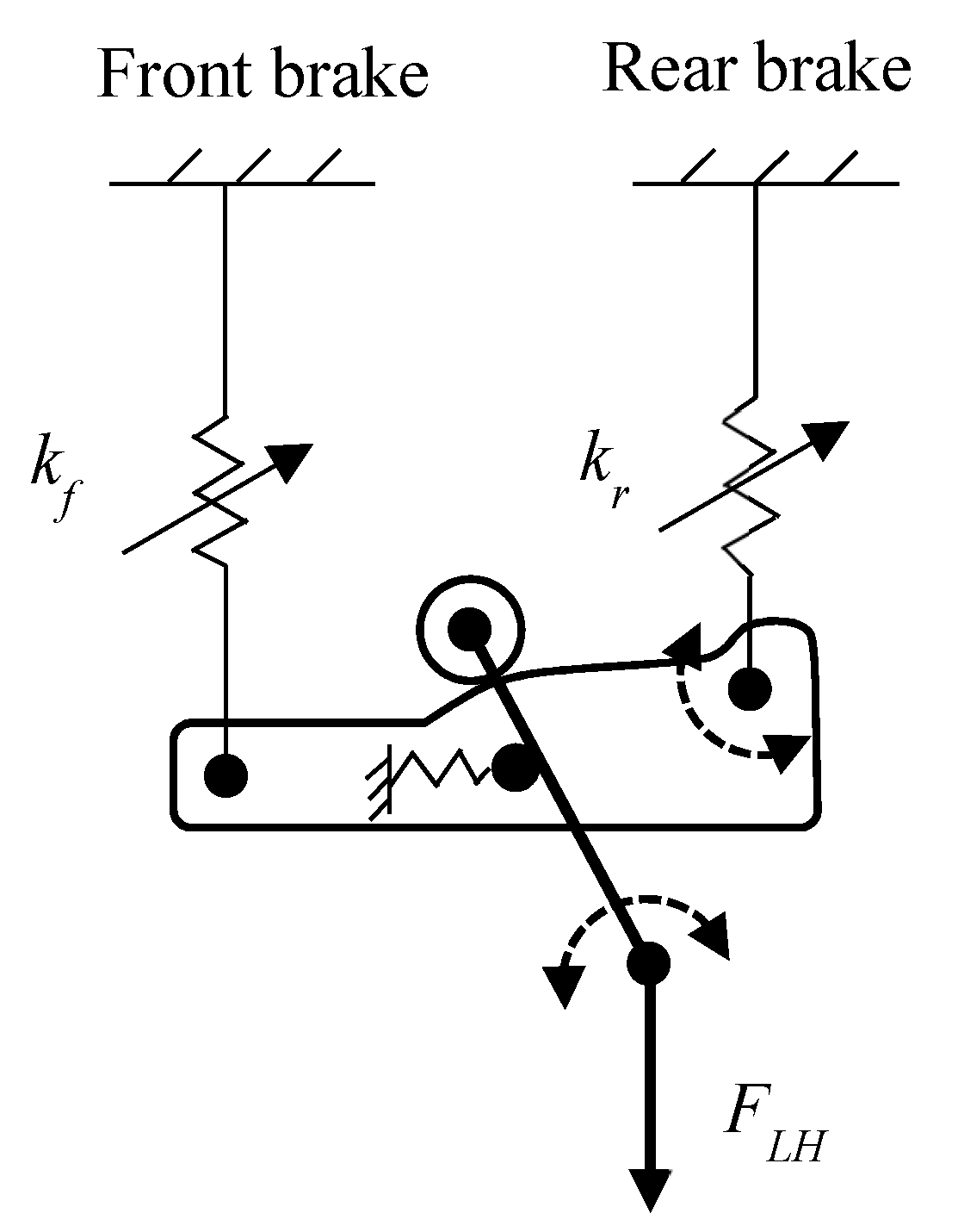
The basic idea behind the VCBS is shown in
Figure 1 schematically. The input force
F is from the left handbrake lever. A floating swingarm is utilized to distribute the input force to the front and rear brake systems. The input force acts on the swingarm’s cam surface through a roller. The magnitude of the input force, the balance of the spring force and the force component due to the cam determine the position of the roller and the force ratio of the front and rear brake systems. Therefore, the number of VCBS’s DOF can be increased to meet the requirements mentioned above simultaneously.
In this mechanism, the cam profile and the returning spring’s rate matching design are critical for the BFD design. The design process requires taking the equivalent stiffnesses of the front and rear brake systems into account since the difference between the displacements of the swingarm’s two sides strongly affects the roller’s balancing position on the cam surface. The cam synthesis procedure has been explored during the last years [
7,
8,
9]. However, because the stiffnesses of the brake systems are highly nonlinear in nature, the relationship between the input force and the BFD ratio by the VCBS is quite complicated. It is challenging to apply the existing methods for the VCBS design directly. First, this paper derives a mathematical model coupling the VCBS mechanism with the brake system’s equivalent stiffness and then proposes a parameter matching design method to resolve this difficulty. Both the simulation and experimental results show that the proposed method possesses the advantages of being feasible, easy to implement, and efficient in generating a cam profile to match the parameters of the VCBS. Road tests are carried out to verify the performance of the VCBS prototype designed by the developed method. Finally, the indexes for evaluating the VCBS’s braking performance are discussed.
2. The Mechanism of VCBS
The VCBS is a force distributor that distributes the input force of the front and rear brake systems. The force distribution ratio of a VCBS (denoted by
Rf hereafter) is defined as, i.e.,
Ff and
Fr in Equation (1) are the forces (N) distributed between the front and rear brake systems, respectively, by the VCBS. With the distributed force, the front and rear wheels generate respective braking forces expressed as:
where
F is the input force (N) to VCBS;
Gf and
Gr are the mechanical gains, and
Ef and
Er are the efficiencies of front and rear brake systems, respectively. Efficiency includes transmitting and mechanical efficiencies. During braking, the maximum available brake forces provided by the front and rear tire-road contact patches,
Ffμ and
Frμ, are determined by [
10,
11]:
where
μ is the road adhesion coefficient,
a the deceleration of the motorcycle in
g,
W the motorcycle’s weight (N),
h the height (m) of center gravity (C.G.),
Lf the distance (m) from the C.G. to the front axle, and
L the wheelbase (m). From Equations (2)–(5)
, the actual braking forces produced by front and rear tire contact patches are:
The braking force distribution (BFD) ratio of the wheels (
RBFD) of a motorcycle on braking is defined as:
For a road condition of
μ, the value of
RBFD that makes the front and rear wheels lock simultaneously is referred to as the ideal
RBFD in this paper. Since the amount of load being transferred increases with the increase of deceleration, the ideal
RBFD is a function of the input force
F from the left handbrake lever. By letting
a =
μ,
Ffw =
Ffμ, and
Frw =
Frμ in Equations (2)–(5), the required
Rf (called
Rf_ideal) for a VCBS that achieves the ideal
RBFD for a motorcycle can be calculated as:
where
,
and
. It is noted that the
Rf_ideal in Equation (9) is determined under the condition of neglecting the effects of the motorcycle’s suspension system. In practice, a VCBS is designed to have an
Rf slightly lower than
Rf_ideal to account for the suspension system’s effect and parametric uncertainties existing in the calculations. From Equation (9), the value of
Rf_ideal varied widely with the input force. For example, the value of
Rf_ideal varied from 0.32 to 0.78 on
F = 0~700 N for the target motorcycle in this study. The design of the VCBS aimed to meet this requirement, that is, having a wide range of
Rf in response to variations of the input force
F.
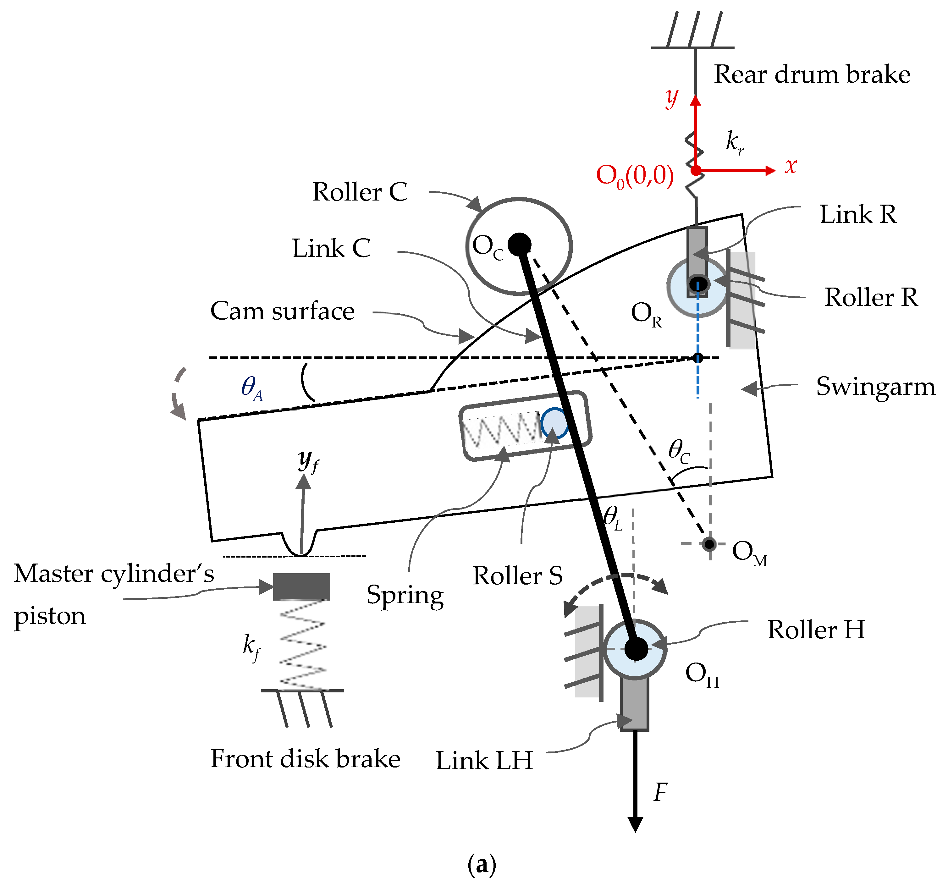
Figure 2 schematically shows the mechanism of the VCBS for motorcycles equipped with front disc and rear drum brake systems in detail. The main component of the VCBS is a swingarm with a contoured cam surface on its upper side. One side of the swingarm is connected to the rear brake wire through a pin that integrates the swingarm with roller R and link R. A bump on the bottom of the swingarm’s left-hand side is designed to push the front brake’s master cylinder piston. Link C is swingable with one end pin-connected to link LH and roller H, while its other end is pin-connected to roller C. The input force
F from the left handbrake lever pulls link C and then roller C to act on the swingarm’s cam surface.
Due to the cam profile, the input force F acting on the roller C generates a force component to move roller C along the cam surface to a balance position. Therefore, the position of F’s acting point can be varied to change the force distribution ratio Rf. To provide the required reacting forces for the movement of roller C, rollers H and R are confined to slide on their respective guides on the mechanism’s shell. A nonlinear returning spring mounted in the slot of the swingarm provides a balancing force against the movement of roller C. In this mechanism, the cam profile and the returning spring’s stiffness are the critical parameters for the braking forces distribution design.
3. Mathematical Model
For all the calculations hereafter, the origin O
0(0, 0) is set at the initial position of roller R’s center, and the weights of all the components in the system are neglected. With the braking forces of the front and rear brake systems (
Fr and
Ff) distributed by the VCBS, the master cylinder piston’s stroke
yf (mm) and the rear brake cable’s stroke
yr (mm) are determined by the equivalent spring rates
kf and
kr of the front and rear brake systems, respectively, i.e.,
where
kf and
kr (N/mm) are measured from the brake systems of the target motorcycle. The stroke difference between the two sides of the swingarm results in the swingarm’s rotating angle
θA (rad) of:
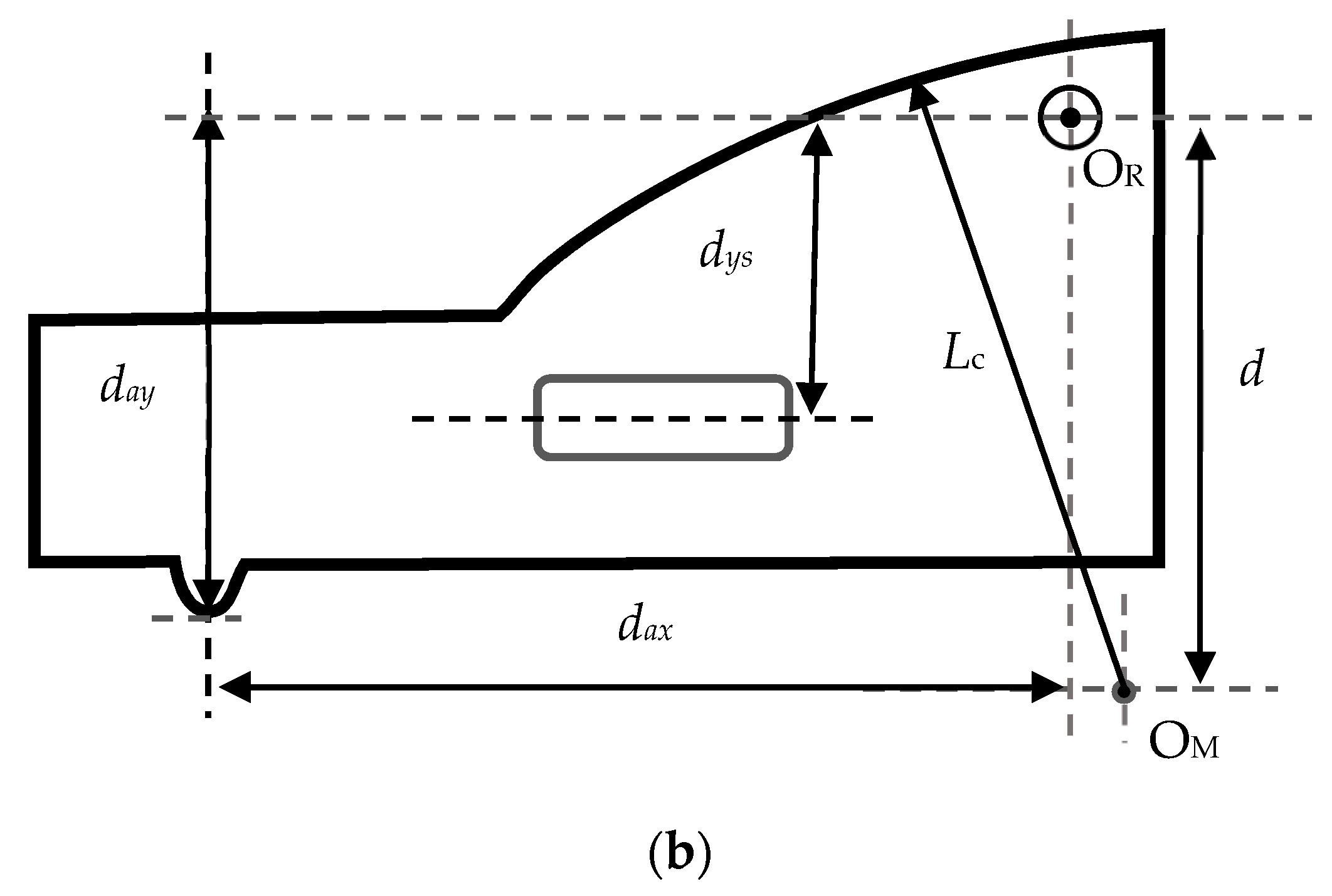
where
dax is the horizontal distance (mm) between the two force acting points of the swingarm, as shown in
Figure 2b.
The cam surface on the swingarm is designed with a variable radius of
Lc centered at O
M(
xm,
ym). According to the geometry of the swingarm shown in
Figure 2b and
Figure 3, the following relationship can be derived as:
where
.
rc is the radius (mm) of roller C;
d is the distance (mm) between O
M (
xm,
ym) and O
R(
xr,
yr);
xh is the horizontal position (mm) of roller H; and
Lh is the length (mm) of link C. The variable
θL is the swing angle (rad) of link C;
θC is the angle (rad) between the
y axis and the line connected by O
C(
xc,
yc) and O
M(
xm,
ym). For the returning spring, a variable pitch spring [
12] that realizes the nonlinear hardening spring characteristics is applied in this study to provide the spring force
Fs expressed as:
where
ks1 (N/mm) and
ks2 (N/mm
3) are the spring rates. The variables
s0 and
ds are the distances (mm) from the center O
R to spring’s free end and roller S’s location, respectively, measured along the returning spring’s axis. In the design stage, the value of
s0 is given to determine the pre-stressed deformation of the spring, and
ds is calculated as:
where
. The variable
dys is the orthogonal distance (mm) between the returning spring’s axis and the center O
R.
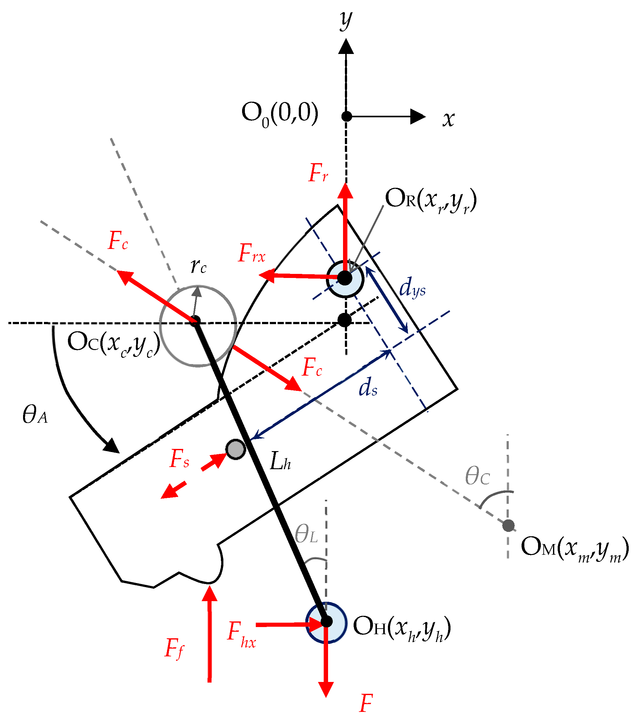
As shown in
Figure 3, the application of input force
F makes roller C generate a normal force,
Fc, acting on the cam surface in the form of
By taking the moment about O
H of link C’s free body diagram in
Figure 3, the relations among
Fc,
Fs,
θA,
θL, and
θC can be obtained as:
where
Lsh is the distance (mm) between rollers S and H, which is calculated as:
Finally, the respective force distributed between the front and rear brakes can be determined by taking the moment about the center O
R using the free body diagram of the swingarm shown in
Figure 3:
4. Parameter Matching Design
Once the mechanical design of the VCBS has been finished, an optimal
Rf curve for a target motorcycle can be obtained (or tuned) by designing a cam profile to match the returning spring’s stiffness (
ks1,
ks2). Thus, a method to generate an optimal cam profile to match the existing VCBS’s parameters is required. The cam profile of the swingarm is a curve centered at O
M(
xm,
ym) with its radius,
Lc, varied with the angle difference
θCA. Since the system that combined the VCBS model and the brake system’s stiffness is complicated and highly nonlinear, it is difficult to directly apply the existing methods of cam profile design. A method that applies the direct one-step-ahead adaptive control technique [
13,
14] is proposed to solve this problem.
For specific values of the spring rates
ks1 and
ks2, the proposed optimal
Lc design is proceeded by building a surrogate model to capture the local behavior of
Rf for
F = 0~700
N. This method, called metamodeling, has been widely used in engineering applications. The surrogate model is used to represent the actual model to reduce computational cost. Extensive research has been carried out to generate the surrogate models based on limited samples [
15,
16]. In this study, a surrogate model is selected to represent the original system (the VCBS model coupled with the brake system’s stiffness):
with
where
F(
k) is the discretized input force that takes values
k = 1, 2, 3, …, i.e.,
F(
k) =
kΔ
F with Δ
F, the sampling value of
F. In control words, the original system can be considered as locally differentially flat since the system’s output
Rf(
k) is visible from its state,
θL(
k) and
θCA(
k), and the input
F(
k) is visible using Equation (20). Flat systems are useful in nonlinear control engineering for explicit trajectory tracking applications. Once the behavior of the flat system can be given by the flat output, planning trajectories in output space and then mapping them to the appropriate inputs are possible; please see [
17] for details. The coefficients in Equation (21) can be estimated online using the Kalman estimator [
18] or the least-squares estimator [
19,
20]. Because the system is free from noise, the sequential least-squares estimator [
21] is applied as follows:
where
is the estimate of
,
ε(
k) the prediction error,
P(
k) the covariance matrix, and
λ the forgetting factor. Initially,
is set arbitrarily, and
P(0) =
αI3×3. A large
α tends to be the high correction of
and therefore tends towards fast convergence. The forgetting factor is in the range of 0.9 ≤
λ ≤ 1; a large
λ behaves with high robustness against disturbance; on the other hand, a small
λ behaves with fast-tracking capability. In this study,
α = 1000 and λ = 0.95 are chosen.
We define the reference model that specifies the ideal response of Equation (20) to the target value
Rf*(
k) as:
where
Rm is the reference model’s output. Since the desired
Rf curve is expected to have a pattern similar to
Rf_ideal, the input to the reference model
Rf*(
k) is defined as
where
Rf0 is a constant used to make the resulting
Rf curve slightly lower than
Rf_ideal, as mentioned previously. We define the tracking error between the reference model output
Rm(
k) and the
estimated by the surrogate model using the newly designed cam profile,
Lc_new(
k), as
The problem is thus to design a controller with output
Lc(
k) to make the plant output
track the reference model output
Rm (
k+1). We define the desired tracking error dynamics as:
where
is selected to determine the error convergence rate. Using Equations (20)–(22) and (26), the left-hand side of Equation (27) can be rewritten as:
Let the right-hand side of Equation (28) be zero to meet the requirement of Equation (27), a new sequence of
Lc(
k) can be obtained and expressed as:
Equation (29) is the adaptive law that generates Lc_new(k) to make (k+1) converge to Rm (k+1), based on the data at instant k.
Remark 1. In Equation (28), the convergence of the tracking error e(k) is guaranteed by selectingand Lc_new in the form of Equation (29), provided that Lc_new is bounded. The boundness of Lc_new is ensured whenholds. Because of the designed geometrical dimensions of the VCBS in this study, the operation range ofis withinfor the target range of Rf within 0 ≤ Rf ≤ 0.6, implying that the boundness of Lc_new(k) is guaranteed automatically.
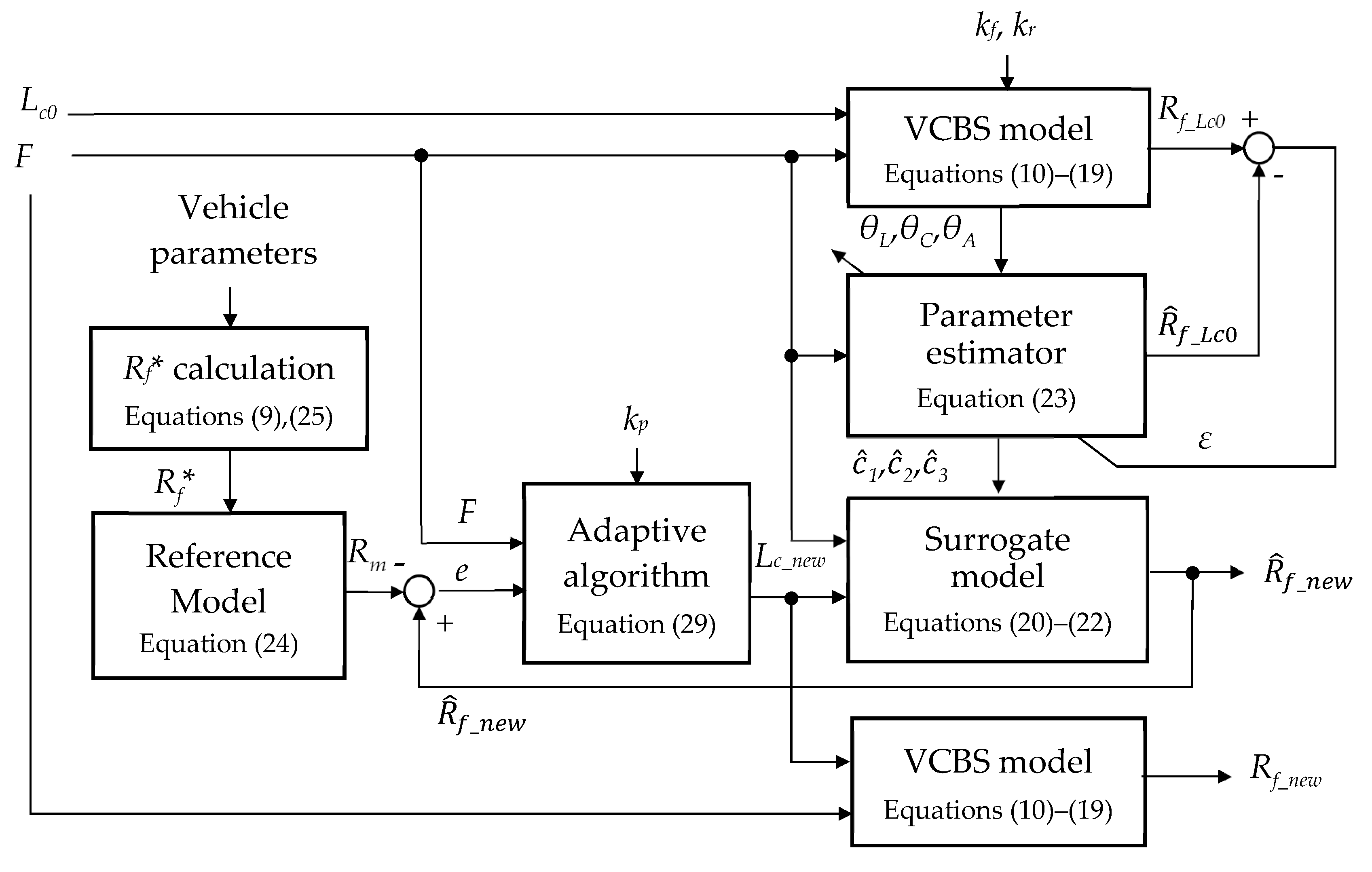
The procedure for designing the swingarm’s cam profile is summarized in
Figure 4. Before starting the design, vehicle parameters such as the center of gravity, mechanical gains and efficiencies, and equivalent stiffness of the brake systems have to be measured. The equivalent brake systems’ stiffnesses are expressed as:
It is noticed that kf represents the relationship between the master cylinder piston’s resisting force Ff (N) and stroke yf (mm), while kr is the relationship between the rear-brake wire’s resisting force Fr and displacement yr. After the kf and kr have been calculated from the measured data, they are expressed as functions of the resisting forces for further calculations. The coefficients in Equations (30) and (31) are obtained through curve fitting. For the target motorcycle in this paper, the coefficients are obtained as: a1 = −0.0006571, a2 = 0.143, and a3 = 1.012; and b1 = 0.0006017, b2 = 0.01, and b3 = 3.633.
The target
Rf curve (denoted by
Rf*) is calculated based on vehicle’s parameters and the required braking performance. After finishing a VCBS’s mechanical design, its geometrical parameters are used to construct the VCBS model of Equations (10)–(19). The cam profile design corresponding to a selected spring rate combination of
ks1 and
ks2 of Equation (13) is started by giving an initial profile of a constant radius of
Lc0. The simulation of the VCBS model generates the
Rf curve corresponding to the
Lc0 (called
Rf_Lc0). Based on the curve
Rf_Lc0, the online parameter estimator of Equation (23) estimates the parameters
of Equation (21). The adaptive law of Equation (29) generates the sequence
Lc_new(
k) that makes the tracking error
e(
k) converge in the case of Equation (27). The sequence
Lc_new(
k) is a function of
θCA, which is used to fabricate the cam profile. For this purpose, an equation is used to represent the cam profile expressed as:
where
b1~
b3 are obtained through curve fitting using the sequence
Lc_new(
k). A design example is demonstrated here by using the parameters of the target motorcycle and VCBS model listed in
Table 1. The parameters for the adaptive law are selected as
kp = 0.5,
Rm0 = −0.3,
Rf0 = 0.1,
am = 0.96, and
bm = 0.04. The spring rates are
ks1 = 8 N/mm and
ks2 = 0.08 N/mm
3. The original cam profile used for the design basis has a constant radius of
Lc0 = 22 mm.
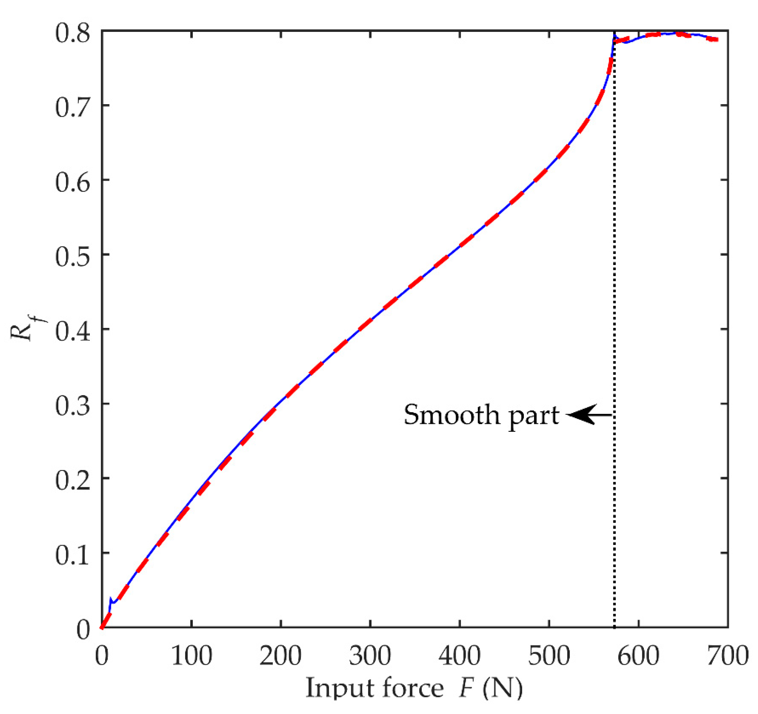
The convergence of the identification procedure is illustrated in
Figure 5 and
Figure 6.
Figure 5 presents the relationship between the trace of
Rf_
Lc0 simulated by the VCBS model and the trace of
predicted by Equations (20)–(22) using the online estimated parameter
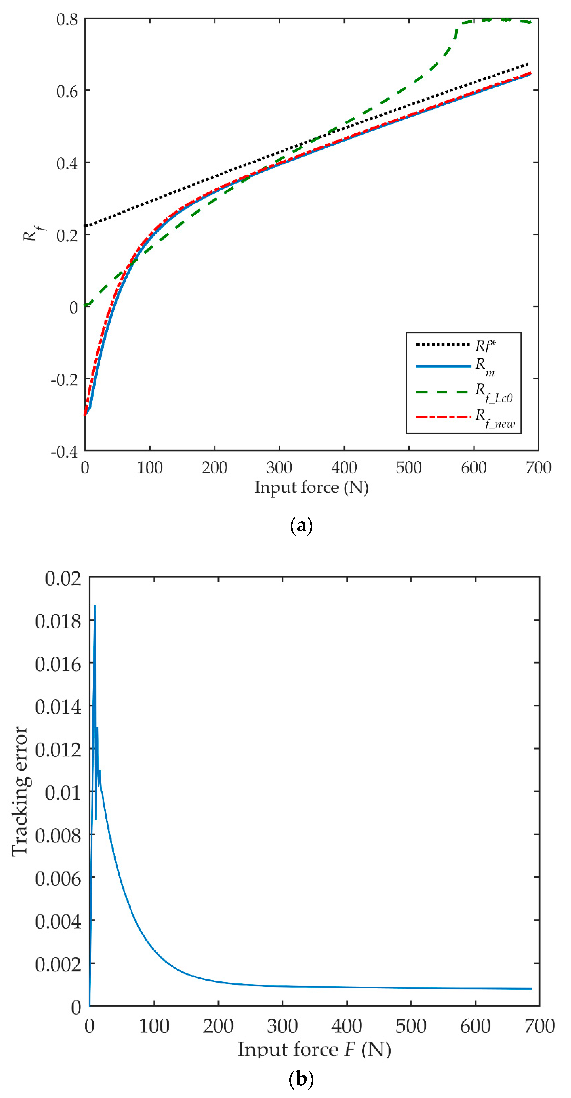
. It can be seen that the predicted output of the surrogate model converges with the VCBS model well. On the other hand, comparing the traces of
Rm,
Rf*, Rf_new, and
Rf_Lc0 in
Figure 6a shows that
Rf_ Lc0 deviates from
Rm significantly, while the trace of
Rf_new tracks the
Rm curve well, with the converged tracking error shown in
Figure 6b. Here, the initial value
Rm0 in Equation (24) is selected to be negative in order to have small values of
Rf_new corresponding to small values of
F.
It is noticed that singularities may exist in Equations (14)–(17) for large values of F depending on the designed parameters of the VCBS. When this happens, a discontinuity followed by an unsmooth sequence can appear on the Rf_Lc0 sequence. Since the smooth part of the Rf_Lc0 sequence spans the entire reasonable operation range of θCA, it is sufficient for generating a satisfactory new cam profile. Therefore, only the smooth part of the Rf_Lc0 is utilized to generate the new cam profile in the design procedure, and the sequence after the discontinuity is discarded. For the present example, the simulation results show that the singularity presents around θCA = 0.945 (rad).
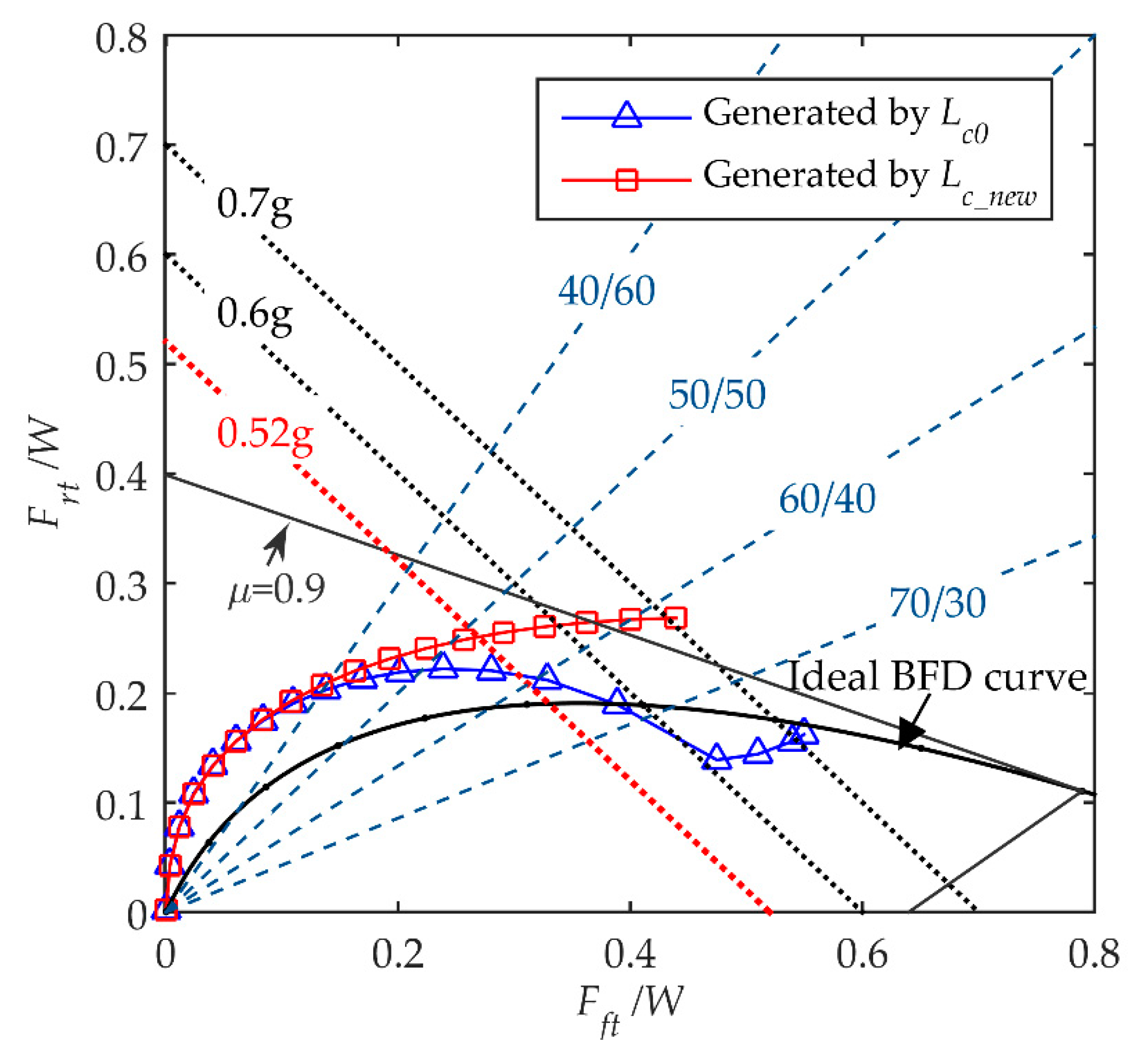
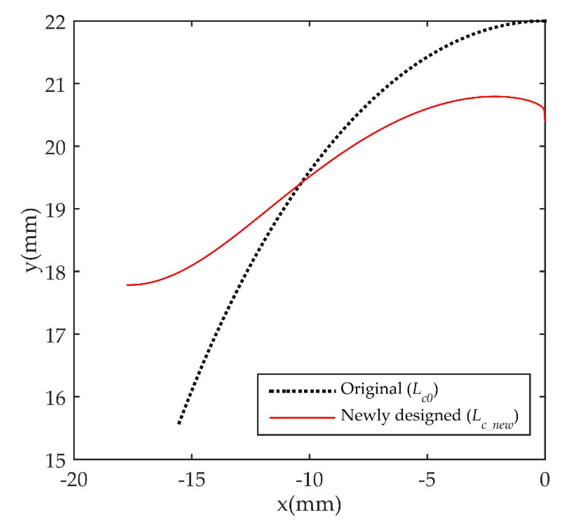
The effect of the newly designed cam profile is shown in
Figure 7. In this figure, the trajectory of dimensionless braking forces
Frt/
W and
Fft/
W, varied with the increase of
F, is defined as the braking force distribution curve (called BFD curve). This curve is useful for evaluating the performance of the VCBS because it can explore the relationship between the variation of decelerations and the force distribution ratio. In this diagram, the ideal BFD curve represents the traces of
Frt/
W and
Fft/
W that make the front and rear wheels locked simultaneously in all road conditions defined by
μ. It can be seen that the original cam profile (
Lc0) generates a BFD curve that falls below the ideal BFD curve on large input forces. This situation is undesirable because it may cause the front wheel to lock first and consequently cause rollover accidents on large braking forces. The BFD curve generated by the newly designed cam profile (
Lc_new) is successfully pulled above the ideal BFD curve for large
F values and has the same changing trend as the ideal BFD. The front braking force distribution ratio varies smoothly with the increase of
F and achieves a high value for large input forces. The improvement of the BFD curve can be understood by observing the two cam profiles on the x-y coordinate shown in
Figure 8. At the positions far from the profile’s center, corresponding to large values of
θCA (so as to large values of
F),
Lc_new is increased gradually compared to
Lc0 and thereby pulls up the BFD curve.
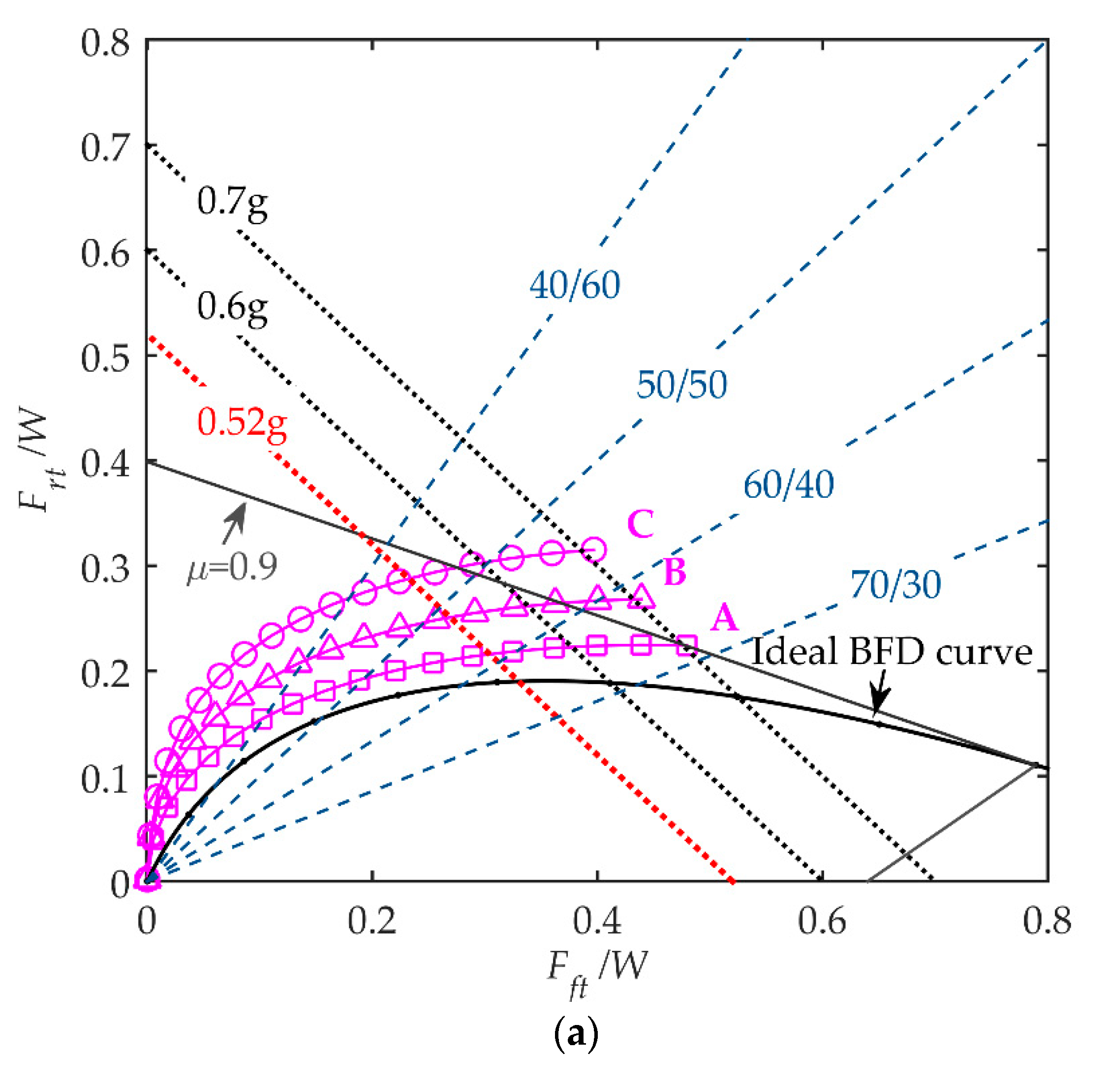
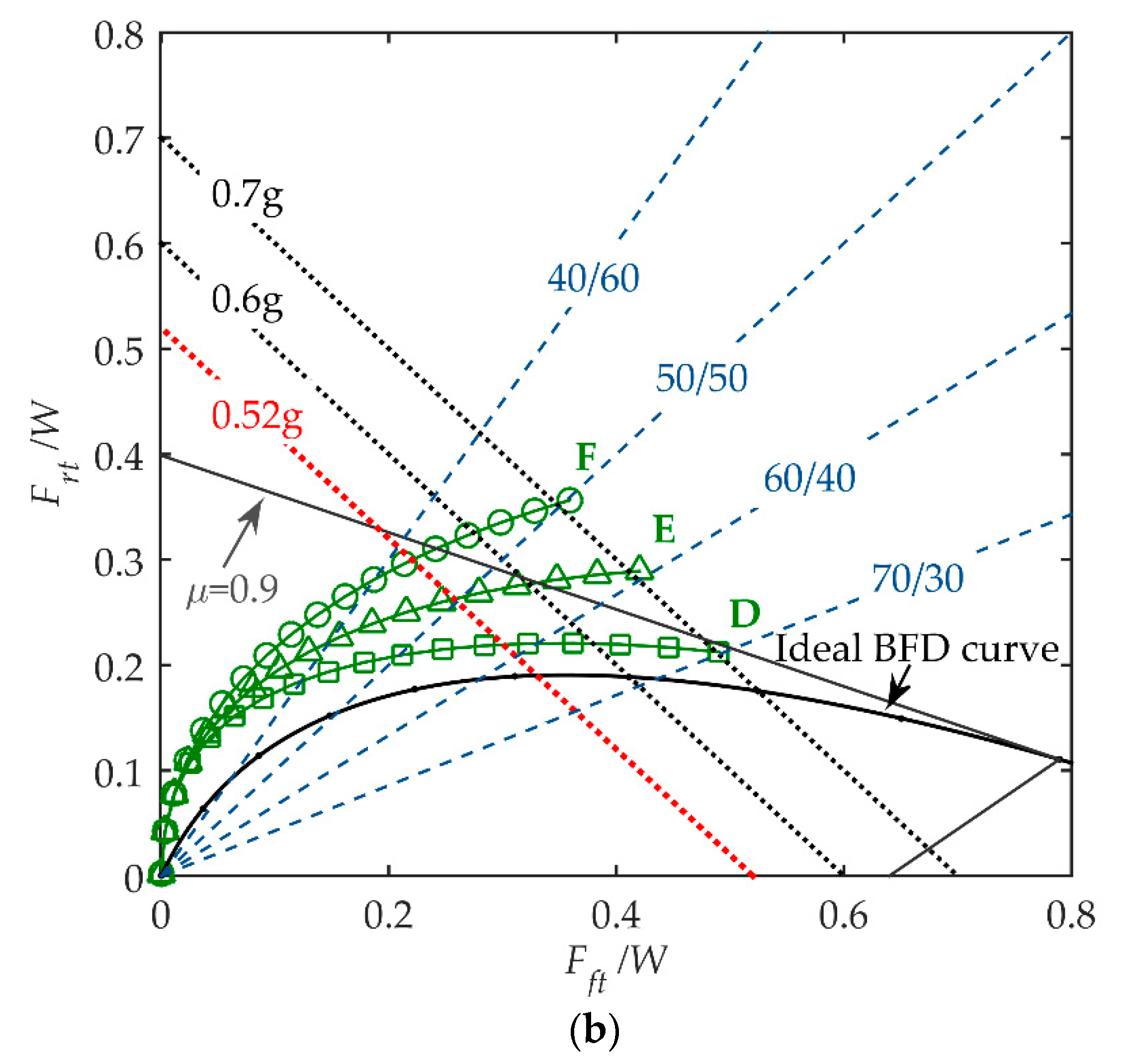
The newly designed cam profile can match various spring rates to obtain different BFD curves.
Figure 9 presents variations of the BFD curve for different spring rates. As shown in
Figure 9a, increases in the linear spring rate
ks1 move the overall BFD curve higher than the ideal BFD curve. On the other hand, the nonlinear spring rate
ks2 affects the curvature of the BFD curve. When
ks2 is increased, part of the BFD curve corresponding to high input forces is turned away from the ideal BFD curve, as shown in
Figure 9b.
5. Design Realization and Road Test Results
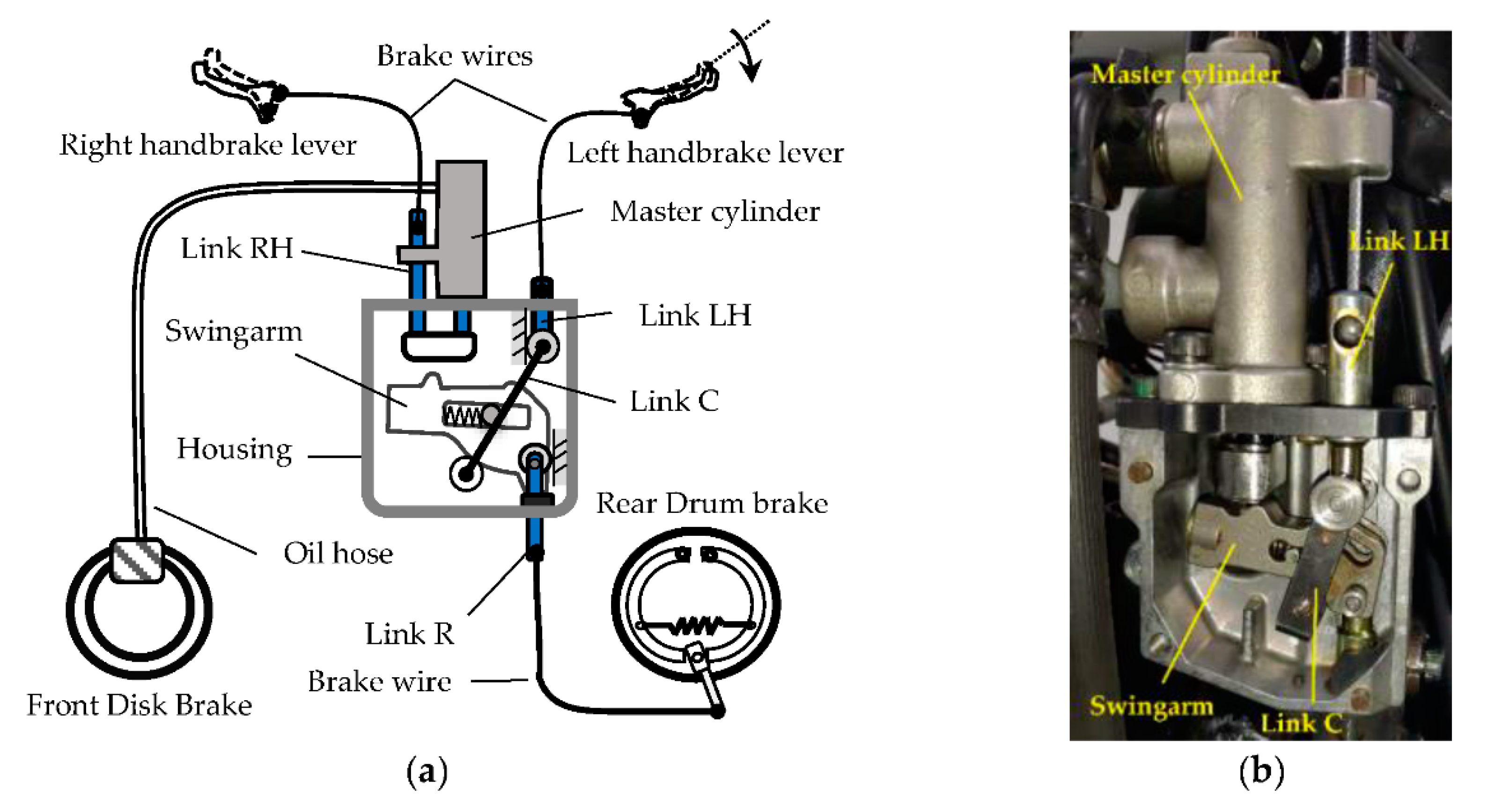
A prototype of the VCBS has been designed and developed based on the design method described in the previous sections.
Figure 10a shows the layout of the VCBS on a motorcycle with a 125 cc gasoline engine and a disc-drum brake system. The input force to the VCBS is from the left handbrake lever through a braking wire, which is the primary source of the motorcycle’s braking force. The right handbrake lever independently activates the front brake by pulling the master cylinder’s piston through a wire. It is only for auxiliary or backup purposes. The prototype’s photo is also presented in
Figure 10b, in which the mechanism’s cover is removed for clarity.
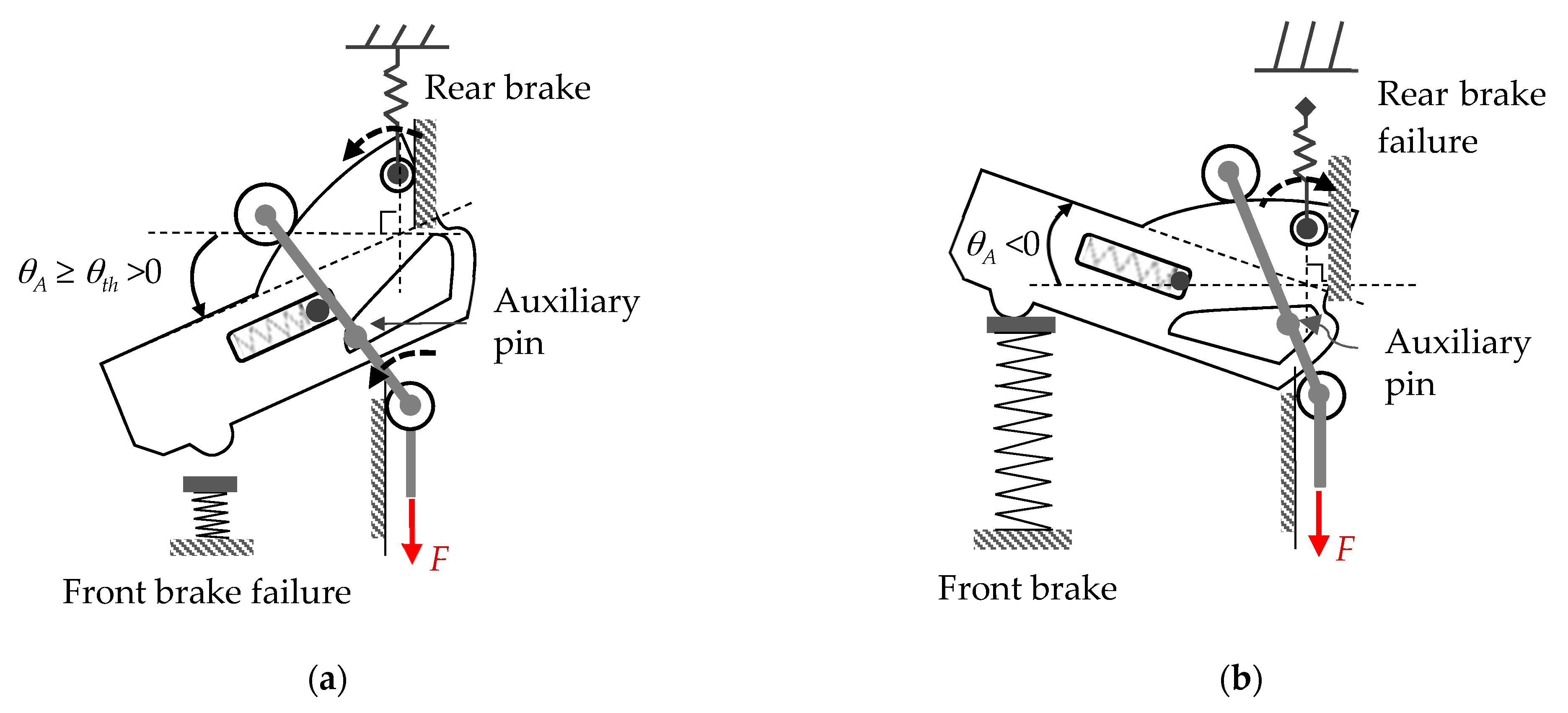
An auxiliary pin mounted onto link C and a slot on the swingarm are designed, as shown in
Figure 11, to achieve a higher deceleration on failure mode operations. The geometry of the slot is well designed so that the following two operation conditions hold:
- (1)
θA ≥ θth >0: the swingarm and link C locked together by the pin, where θth is the maximum allowable anticlockwise rotating angle of the swingarm.
- (2)
θA < θth: the pin without contact with the boundary of the slot.
The first condition is for front brake failure mode. When the master cylinder piston loses its resisting force against the swingarm because of front brake failure, its anticlockwise rotating angle θA could become enormous. If θA ≥ θth holds, the auxiliary pin will contact the slot’s boundary to lock the swingarm with link C. Under this condition, the swingarm can no longer rotate such that the rear brake takes all the magnitude of the input force F. On the other hand, with rear brake failure, the swingarm loses the brake wire resisting force acting on the roller R, and the input force F makes the swingarm rotate clockwise freely. Consequently, both the front and rear brake receive no braking forces on the application of F. The value of θth is a compromise between the required deceleration on front brake failure and the maximum desired Rf value in a normal condition. In this study, θth = 6° is selected.
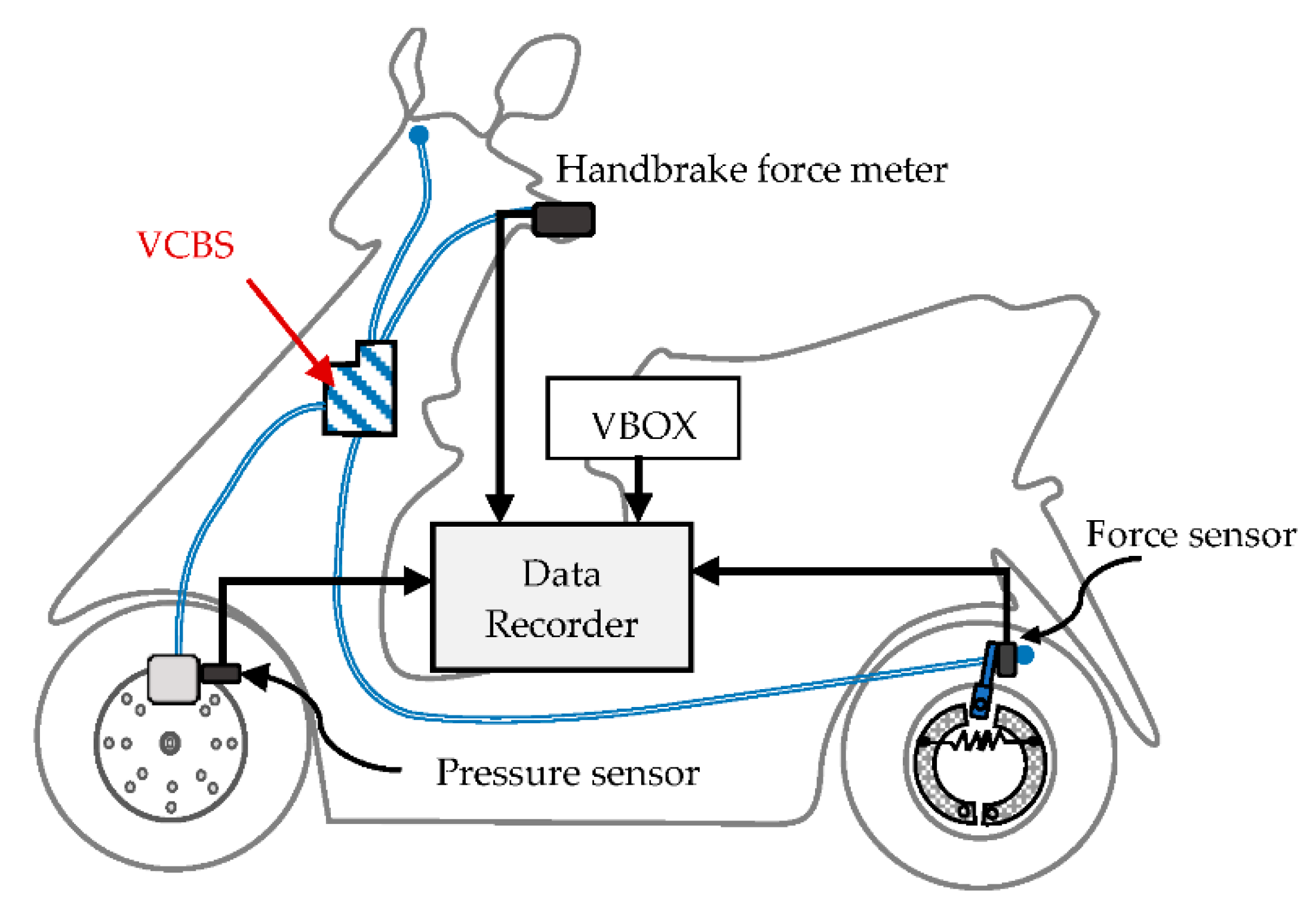
The straight-line braking test is carried out on the studied motorcycle to verify the performance of the VCBS. The measurement system includes the VBOX speed sensor to acquire speed, deceleration, and braking distance; a handbrake meter to measure the driver’s input force; a hydraulic pressure transducer installed on the caliper of the front brake, and a force sensor installed on the rear brake wire, as shown in
Figure 12. The tests [
22] are performed by a skilled driver on a standard road condition with an adhesion coefficient of about 0.9. When the vehicle accelerates to more than 60 km/h and reaches the brake start sign on the roadside, the driver presses the left handbrake lever (with force not larger than or equal 200 N within 0.6 s) to activate the VCBS and stop the motorcycle in an emergency. When the motorcycle stops, the braking distance is measured, and the recorded data during braking are stored.
Table 2 presents three test cycles’ recorded data, including the averaged maximum left handlever force, brake triggering speed, MFDD (Mean Fully Developed Deceleration) [
22,
23], and braking distance. The test results show that, with the averaged maximum handbrake lever force of 190.54 N, the averaged MFDD is 6.37 m/s
2—much higher than the homologation requirement of 5.1 m/s
2 (0.52 g).
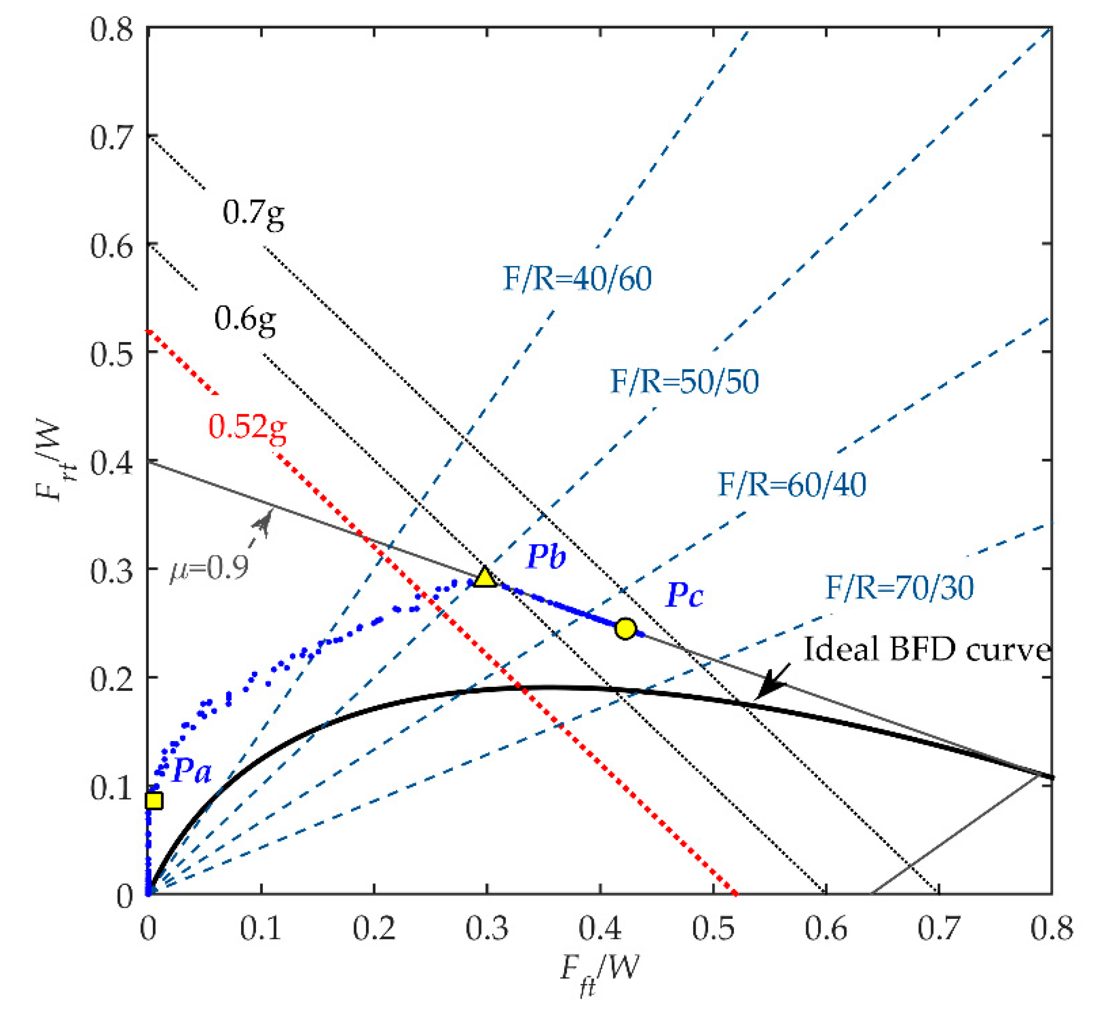
The dynamic left handbrake lever force, the front braking force calculated from the measured pressure, and the rear braking force during braking are used to plot the BFD curves as shown in
Figure 13. There are three performance metrics for the BFD curve concerning braking performance and driving comfort:
Pa,
Pb, and
Pc. The dimensionless rear braking force
Frt/W at point
Pa represents the dimensionless delaying force of the front brake. A sufficiently large value of
Frt/W at point
Pa can avoid the occurrence of rollover accidents caused by the front wheel locking first for all road conditions and help lower the motorcycle’s pitch rate on low braking forces operation, thus improving driving comfort. It is the professional drivers’ opinion through subjective evaluation that the optimal dimensionless delaying force
Pa for the studied motorcycle is within 0.08 <
Frt/W < 0.1 at laden load. The tested result is within an average of 0.09, which agrees well with the requirement.
Pb is the point where the BFD curve intersects with the line μ = 0.9 and the rear tire starts to skid. At this point, the values of the braking force distribution ratio of wheels (RBFD), which is defined in Equation (8), and the deceleration are of interest. It is required that the deceleration at Pb is as high as possible to achieve high braking performance. A higher value of RBFD is required to obtain higher deceleration corresponding to Pb, which is the purpose of the VCBS design. The curve shows that the averaged deceleration corresponding to the point Pb is 5.77 m/s2 (0.59 g) and RBFD = 0.507.
After passing through the point
Pb, deceleration is increased with the increase of the input force
F due to the increase of the front braking force (
Fft). Since the deceleration of the motorcycle, contributed to by the rear braking force, is decreased, the slope of the BFD curve is turned negatively. The curve ceases at the point
Pc corresponding to the maximum input force. The estimated averaged maximum deceleration at
Pc is calculated as 6.54 m/s
2, which approaches the averaged MFDD test result of 6.37 m/s
2. For the front brake failure mode test, the tested MFDD is with an average of 3.38 m/s
2, higher than the 2.9 m/s
2 of homologation requirement, as listed in
Table 3. All the road test results verify that the VCBS prototype can achieve satisfying deceleration performance and driving comfort.


