Article

Design and Multi-Objective Optimization of a 12-Slot/10-Pole Integrated OBC Using Magnetic Equivalent Circuit Approach

1
Smart-CI Center, Alexandria University, Alexandria 21526, Egypt
2
Department of Electrical Engineering, Cairo University, Cairo 12613, Egypt
3
Department of Electrical Engineering, Alexandria University, Alexandria 21526, Egypt
4
Department of Electrical and Control Engineering, Arab Academy for Science, Technology and Maritime Transport, Alexandria 21913, Egypt
5
CEMSE Division, King Abdullah University of Science and Technology, Thuwal 23955, Saudi Arabia
*
Author to whom correspondence should be addressed.
Machines 2021, 9(12), 329; https://doi.org/10.3390/machines9120329
Submission received: 3 November 2021 / Revised: 27 November 2021 / Accepted: 30 November 2021 / Published: 1 December 2021
(This article belongs to the Special Issue Innovative Applications of Multiphase Machines)

Abstract

:
Permanent magnet machines (PMs) equipped with fractional slot concentrated windings (FSCWs) have been preferably proposed for electric vehicle (EV) applications. Moreover, integrated on-board battery chargers (OBCs), which employ the powertrain elements in the charging process, promote the zero-emission future envisaged for transportation through the transition to EVs. Based on the available literature, the employed machine, as well as the adopted winding configuration, highly affects the performance of the integrated OBC. However, the optimal design of the FSCW-based PM machine in the charging mode of operation has not been conceived thus far. In this paper, the design and multi-objective optimization of an asymmetrical 12-slot/10-pole integrated OBC based on the efficient magnetic equivalent circuit (MEC) approach are presented, shedding light on machine performance during charging mode. An ‘initial’ surface-mounted PM (SPM) machine is first designed based on the magnetic equivalent circuit (MEC) model. Afterwards, a multi-objective genetic algorithm is utilized to define the optimal machine parameters. Finally, the optimal machine is compared to the ‘initial’ design using finite element (FE) simulations in order to validate the proposed optimization approach and to highlight the performance superiority of the optimal machine over its initial counterpart.

1. Introduction

Battery chargers can either be installed at charging stations, known as off-board chargers, or mounted on electric vehicles (EVs), known as on-board chargers. Although off-board chargers offer high power transfer capability, their installation cost is substantially high. On the other hand, on-board battery chargers (OBCs) are cost-effective units that can be directly connected to the grid; however, their power transfer capability is restricted because of weight, space, and cost constraints. To alleviate the problems associated with OBCs and the lack of charging points, integrated OBCs have been the topic of a significant body of recent literature [1]. The proposed charging topology integrates the drivetrain elements into the charging process, thus facilitating the deployment of fast three-phase charging [2].
Various electric machines can be used in EVs, namely the induction motor (IM), permanent magnet synchronous machine (PMSM), and switched-reluctance motor (SRM) [3]. IMs have been utilized in several Tesla Models (e.g., Model S, Model X, and Roadster). Meanwhile, the electric traction machine used in the Volkswagen e-Golf is a PMSM [4]. Despite being cost effective and providing good traction performance [5], practical employment of SRMs in commercial EVs is very limited due to the machine’s high torque ripple. It is worth mentioning that PMSMs have the highest efficiency among all other EV drivelines, both three-phase and multiphase configurations. The prime motivation to employ multiphase-based machines in EV applications, besides fault tolerance capability and decreased converter per phase current rating, is the higher degrees of freedom that ensure zero average torque production during the charging process [6].
Performance wise, PM machines equipped with a fractional slot concentrated winding (FSCW) have shown promise in EV applications, as they correspond to a substantial improvement in torque/power densities [7]. Among all possible winding layouts, e.g., the six-phase asymmetrical, six-phase symmetrical, dual three-phase layouts, the six-phase asymmetrical configuration gives better rotor loss index when compared to the dual three-phase one under both the propulsion and charging modes of operation owing to its superior MMF spectra [2]. Recently, the optimal design of FSCW-based PM machines has been investigated in the literature [8,9]. From the perspectives of torque components and core losses, the asymmetrical six-phase winding configuration is superior when compared to the dual three-phase one in the motoring mode. Meanwhile, the forces during charging for the dual three-phase machine are much higher than those for the asymmetrical winding machine [8]. Therefore, the six-phase asymmetrical machine is selected for this study.
Machine design optimization can broadly be categorized into single-objective optimization and multi-objective optimization. The former can easily optimize a single variable at a time; however, it may have a negative impact on the EV drivetrain performance. On the other hand, the latter can meet multiple design requirements while considering the interaction between variables [10]. In [11], Wang et al. illustrated that magnet width can highly reduce torque ripple on the basis of single-objective optimization. Zhu et al. proposed an efficient multi-objective optimization strategy for a less-rare-earth PM machine [12]. In this work, the selected objectives constitute the output torque, PM cost, cogging torque, torque ripple, and efficiency. As a result, lower PM cost has been achieved. In [9], Zhu et al. introduced an emerging multi-level optimization design of a less-rare-earth hybrid PM machine, i.e., motor level optimization, followed by control-level optimization. The average torque, torque ripple, and demagnetization have been selected as the objectives in the motor design level. Based on the resonance compensation strategy, the torque ripple and speed vibration level have been effectively adjusted in the motor control level.
Although most of the previous multi-objective optimization strategies were mainly based on numerical techniques such as 2D and 3D finite element (FE) models, recent literature has proposed some alternatives based on parametric magnetic equivalent circuit (MEC) models [13], which is a notable contribution of this analysis. FE techniques are the most accurate; however, owing to the heavy computational burden and the cumbersome operations, MEC-based models are highly preferred because of their low computational costs during the initial design stages [14,15]. The main drawback of the MEC modeling approach is that the flux leakage cannot be captured. Conversely, taking the spatial harmonic contents into consideration, the accuracy of the MEC model in combination with the meshing method is highly improved [16]. Moreover, Fourier-based MEC modeling efficiently considers the eddy current effects [17].
Design optimization of PM machines using both FE and MEC models has been thoroughly discussed in the literature under the propulsion mode of operation [18]; however, this paper proposes the design and optimization of an integrated OBC using an asymmetrical six-phase 12-slot/10-pole SPM machine based on the efficient parametric MEC approach. In [8], the influence of various design parameters, namely the slot-opening width and PM width to pole pitch ratio, on the torque ripple and core losses under both modes of operation was thoroughly addressed, and the optimal solution was selected based on the Pareto optimization technique. The main contributions of this study over the one presented in [8] are summarized in the following bullets:
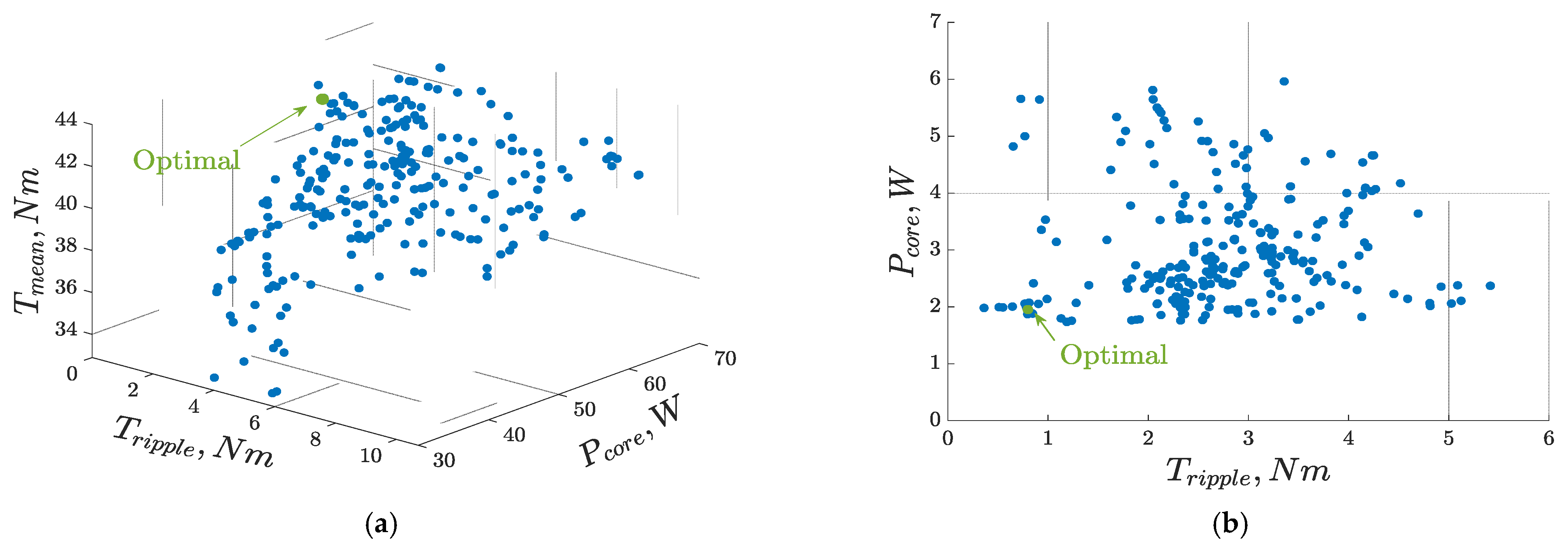
  • Multi-objective genetic algorithm (MOGA) optimization of the employed integrated OBC considering average output torque, torque ripple under propulsion, core losses under propulsion, torque ripple under charging, and core losses under charging.
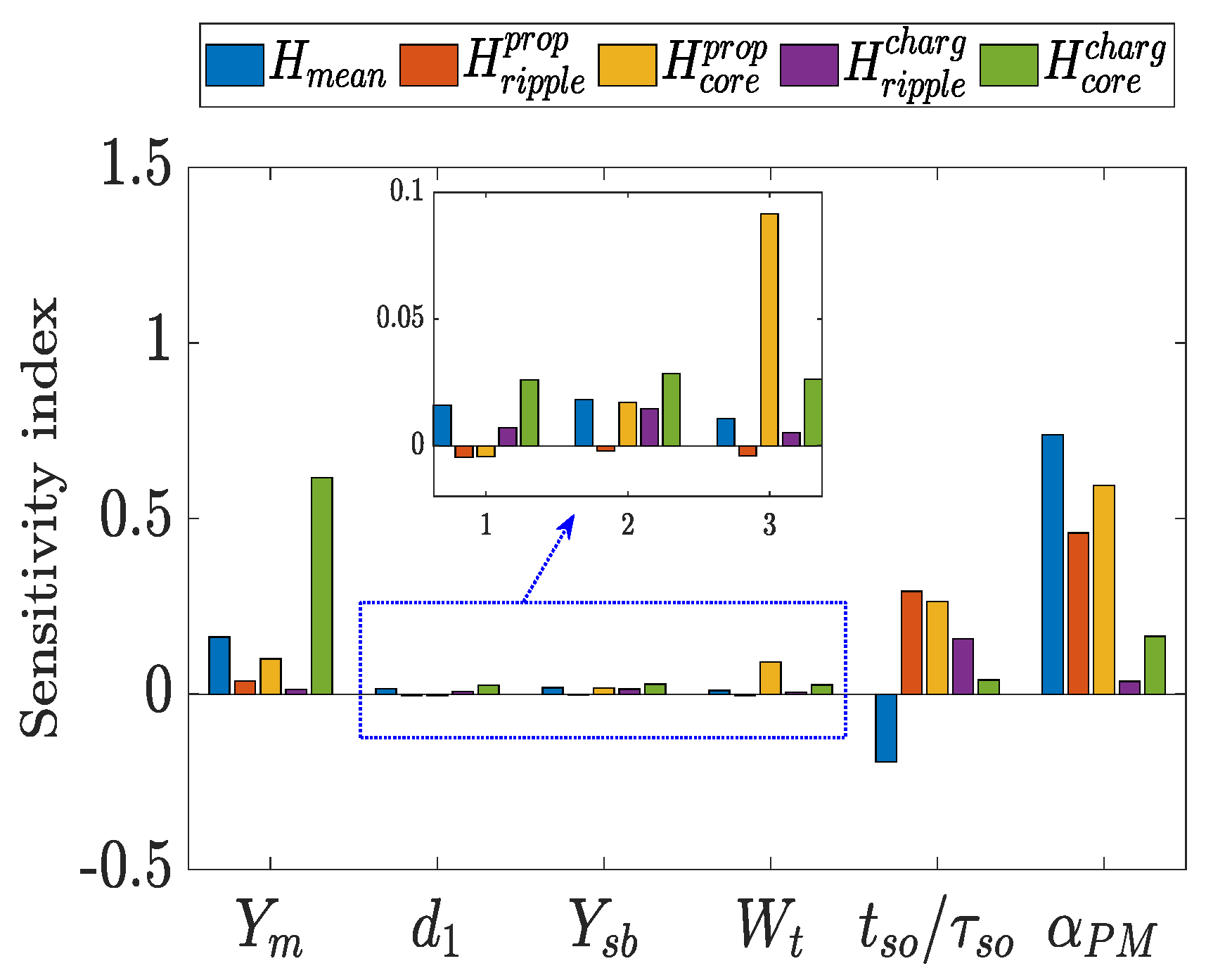
  • Sensitivity analysis to identify the influence of each design parameter on the various optimization performances of the SPM machine.
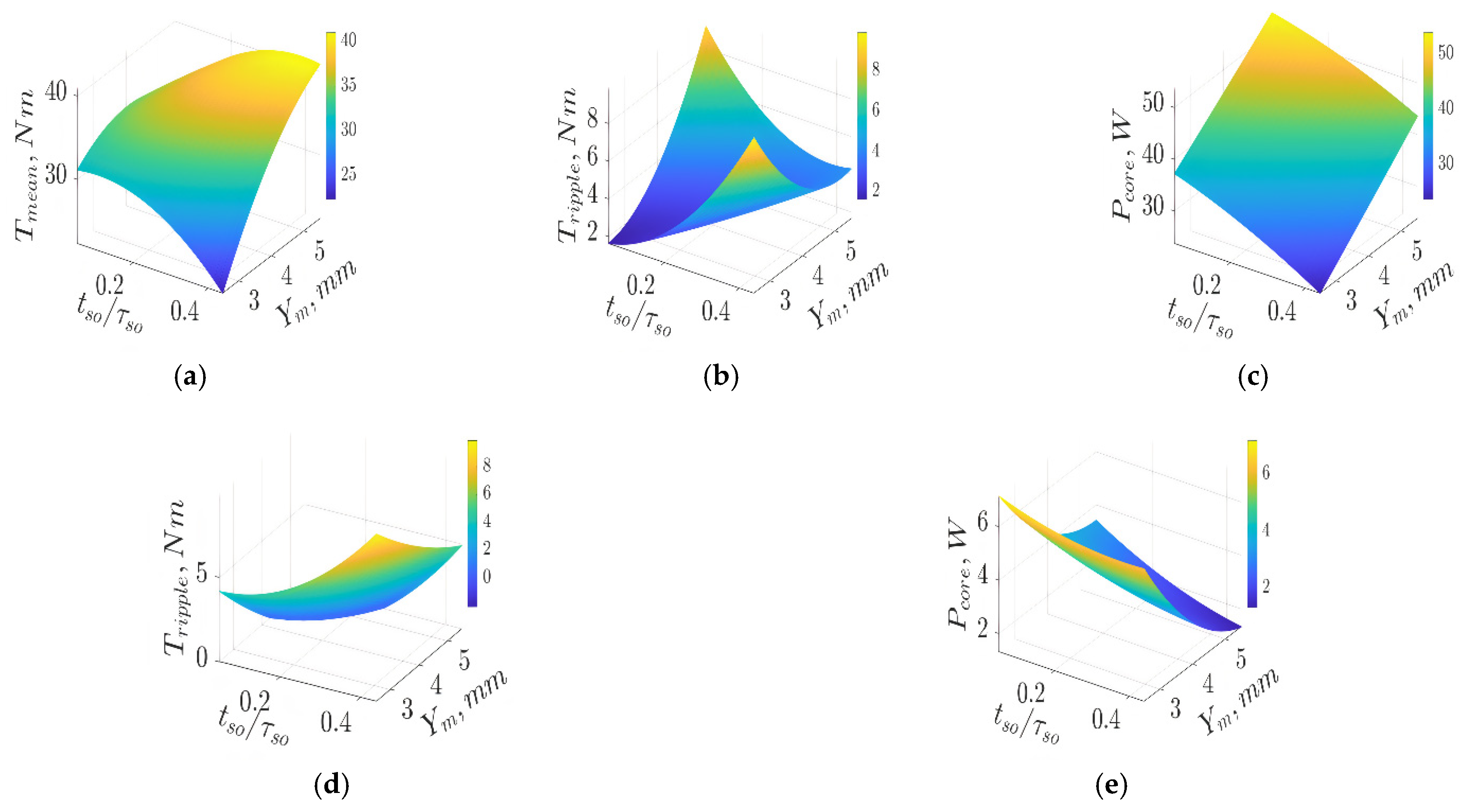
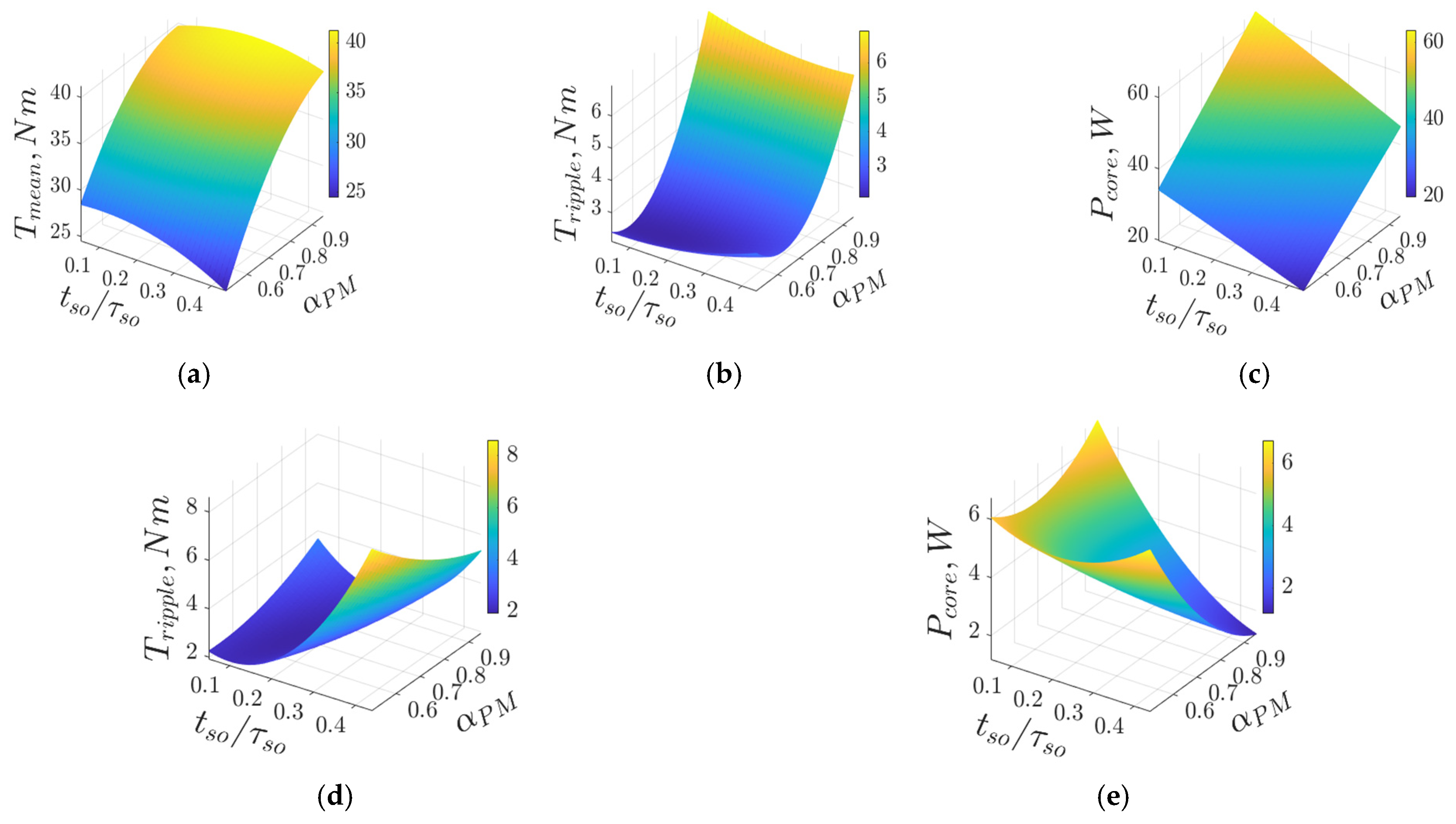
  • Response surface (RS) methodology to illustrate the relationship between the optimization objectives and high-sensitive design parameters.
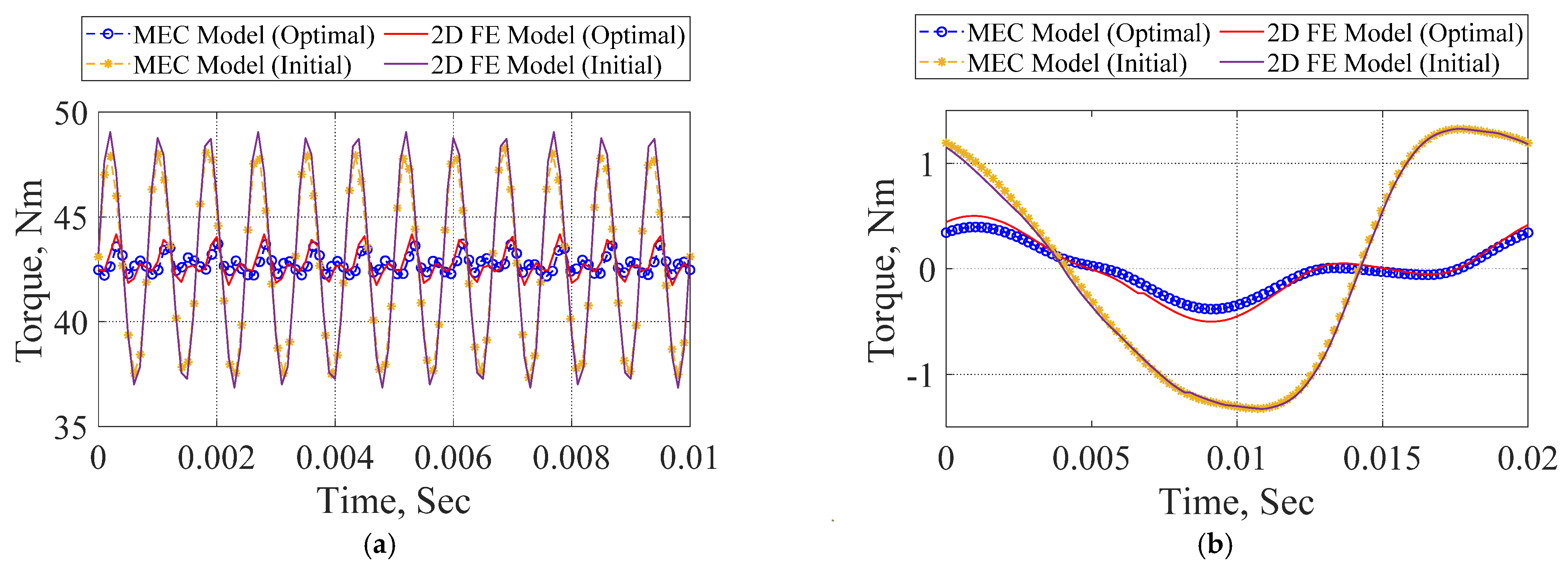
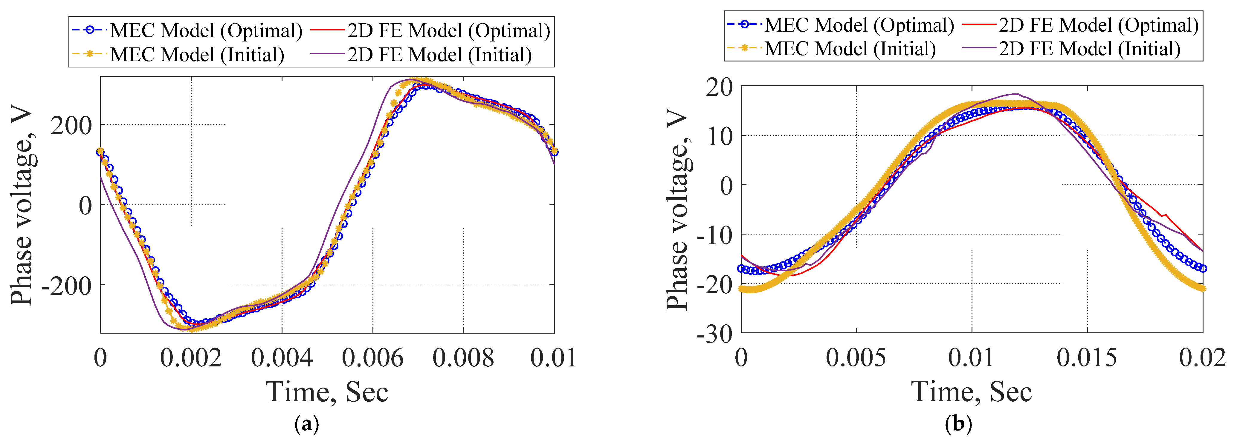
  • Improved electromagnetic performances, namely, torque profile and core losses, under both operational modes were obtained and validated using finite element analysis (FEA).

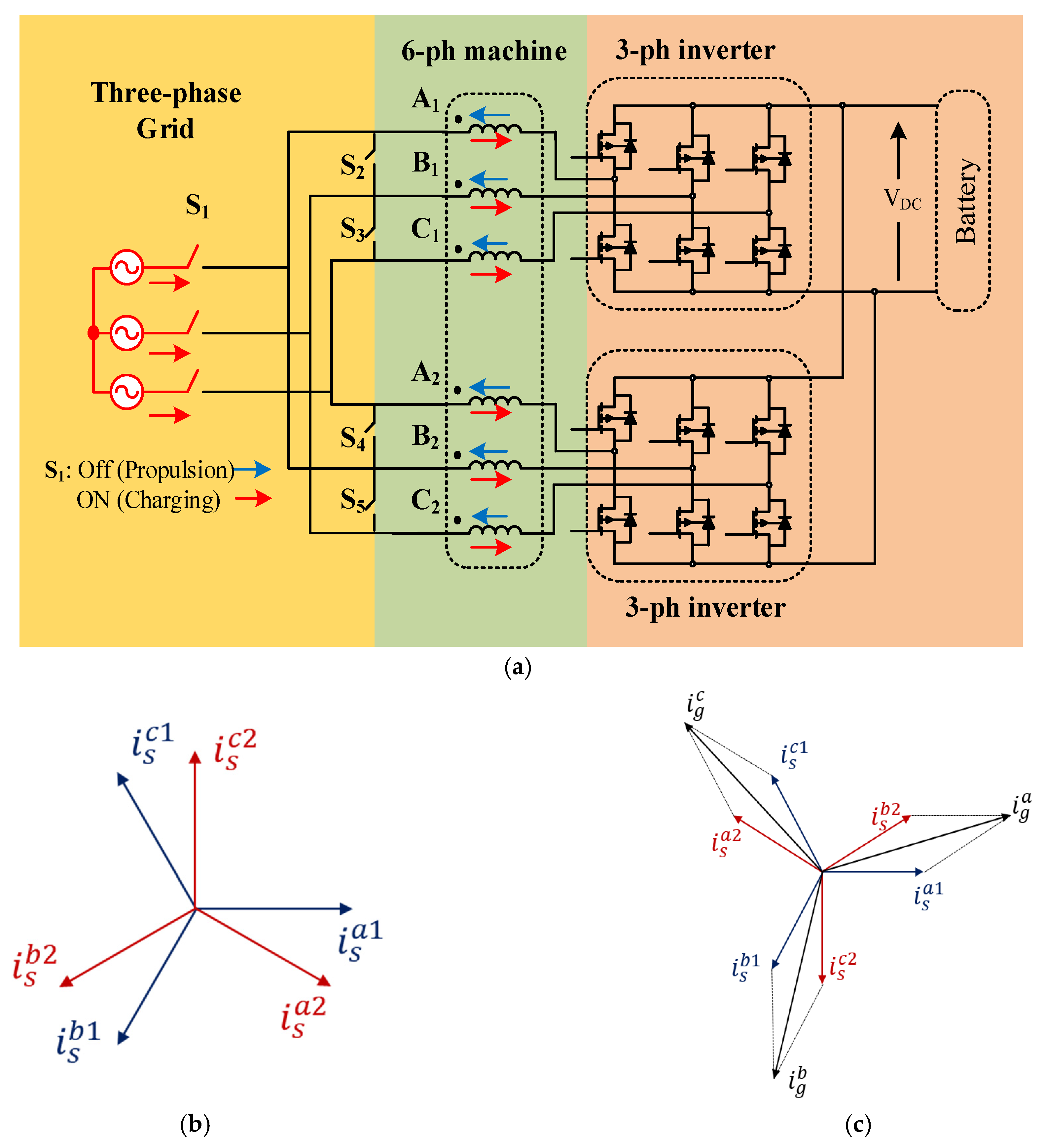
2. Design Requirements and Integrated EV Charging Application

During charging mode, a low peak-to-peak torque ripple is required to reduce vibrations and noise in SPM machines. Core losses are also important, since they may lead to thermal demagnetization. Typically, application requirements are utilized as input to the machine design process. Design specifications for a scaled SPM machine are given in Table 1. In this paper, an asymmetrical six-phase integrated OBC is presented and designed, as depicted in Figure 1. It comprises a six-phase machine, an inverter, and a battery connected to a DC-DC converter to control the DC link voltage. The DC link voltage is maintained at 600 V through the boost DC-DC converter [19]. This study investigates the asymmetrical six-phase winding topology under propulsion ( δ = 30 ° ), as well as charging ( δ = 210 ° ), where δ is the spatial phase angle between the two three-phase winding groups.
The proposed charger offers zero average torque production in the charging process when switch S 1 is on and switches S 2 S 5 are off. In that case, after synchronization, the grid line currents i g a , i g b , and i g c are divided between the first three-phase winding set with to the phase sequence i s a 1 , i s b 1 , and i s c 1 and the second three-phase winding set with the phase sequence of i s b 2 , i s c 2 , and i s a 2 . Thus, the resultant magnetic fields of the fundamental subspace from the two winding groups oppose each other, yielding a zero-torque-producing magnetizing flux component [20]. Moreover, the reference charging phase currents are derived based on the direct component of the grid line currents, while the quadrature current component is set to zero. Unity power factor operation at the grid side is, therefore, guaranteed. The six-phase windings are utilized as grid-side filters [21].
Under propulsion, switch S 1 is off, and switches S 2 S 5 are on, the two three-phase winding sets are connected in series forming a single neutral point topology, while each three-phase winding group is fed from a separate three-phase inverter. As a result, it can be noted that the proposed integrated OBC entails simple hardware reconfiguration between the propulsion and charging modes using switches S 1 S 5 .

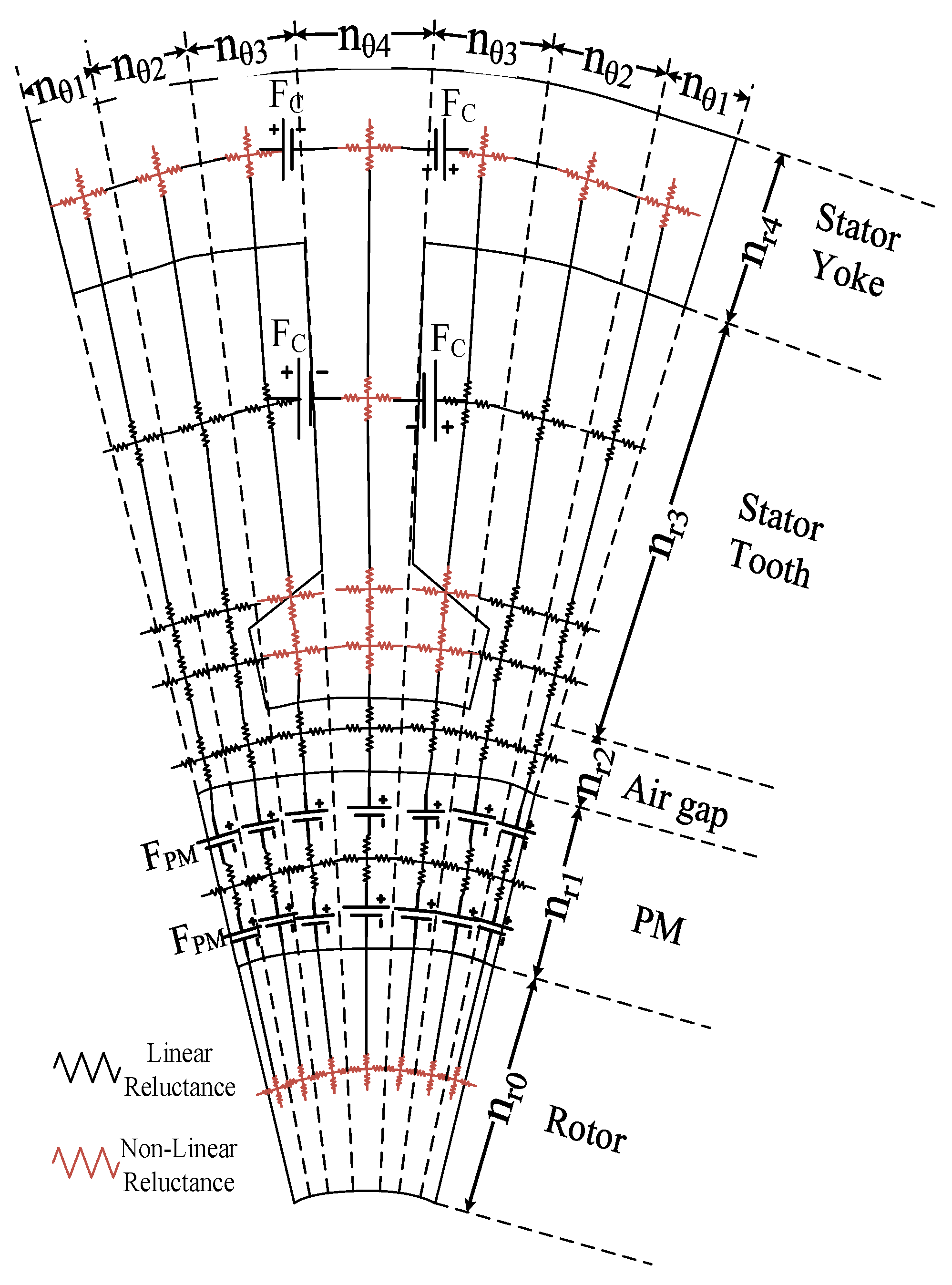
3. Parametric MEC Model

The MEC model proposed in [18] was developed for axial flux permanent magnet synchronous machines. The model is adjusted for radial flux permanent magnet synchronous machines (RFPMSMs) and is employed in the optimization process.
Figure 2 shows a one-tooth pitch defining all parts of the machine. The machine is divided into the rotor, the permanent magnets, the air gap, the tooth, and the yoke. Each tooth is divided into three parts consisting of the tooth tips and the tooth main part. Modeling of each part is performed using the MEC model. The saturation of the iron is included in the model by defining the non-linear reluctance elements. The connection between all elements is achieved using the loop matrices [18].
The model is divided into several nodes. The values of n r 0 = 2, n r 1 = 3, n r 2 = 2, n r 3 = 10, and n r 4 = 2 define the amount of discretization in the radial direction of the rotor yoke, PMs, air gap, stator tooth, and stator yoke, respectively. The discretization in the circumferential direction is defined by n θ 1 , n θ 2 , n θ 3 , and n θ 4 , where the value of n θ 1 , n θ 2 , n θ 3 , and n θ 4 used in this study are 8, 18, 13, and 13, respectively. This allows a detailed discretization in a certain part of the machine.
The system matrix consists of the reluctance elements and the magnetomotive force of the windings and the PMs.
Modeling of the PMs is performed by defining the magnetomotive force sources of the PMs as a Fourier series expansion in the circumferential direction for the PMs. Rotation of the PMs is performed by including the time in the Fourier series. The average magnetomotive force between two points can be easily obtained by an analytical formula. The details of obtaining the magnetomotive force of the PMs can be found in [18]. Therefore, the stator and rotor reluctance matrices are kept constant and the only moving elements are the magnetomotive forces. This allows a fast and accurate solution for all electromagnetic parameters.
The reluctances of the machine consist of linear and non-linear elements. Therefore, a Jacobian matrix is defined to solve the machine by using the Newton–Raphson technique. The procedure and the equations can be found in [18]. As shown in Figure 2, the model considers the variation of the reluctances in the radial direction.
After obtaining the flux density distribution in all stator and rotor iron parts, the iron losses can easily be obtained using the concept of the iron losses separation technique [22]. Finally, all electromagnetic parameters can be obtained. This includes the flux linkage for each phase, the full-load voltages, the mean torque, the torque ripple, the cogging torque, and the iron losses. All electromagnetic properties are verified by means of finite element (FE) analysis at the end of the article.
During the iterative design process, the model is fully parameterized in terms of the geometrical machine parameters, the number of slots, the number of poles, and the number of phases. The same model can be used for propulsion and charging modes.

4. Motor Topology and Optimization Model
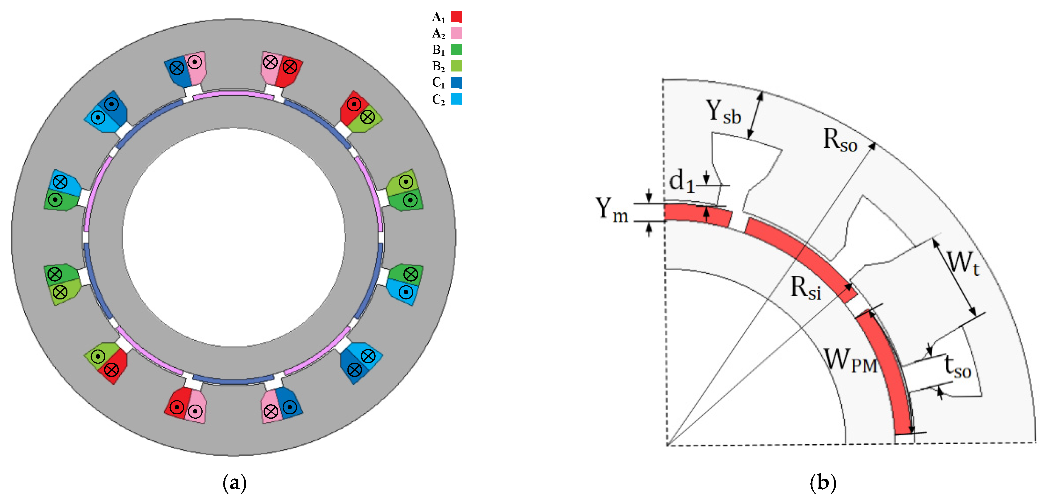
4.1. Motor Topology

Among the various available PM machine topologies, the SPM machine equipped with an FSCW is adopted in this study. Figure 3a depicts the model of the employed asymmetrical six-phase 12-slot/10-pole PM machine, while the parametric model that highlights the selected design variable is shown in Figure 3b. The application of FSCW-based SPM machines in EVs is of particular interest, not only for its shorter end turns and high slot fill factor, but also for the higher torque density and inherent fault-tolerance capability [23]. The corresponding MMF harmonic spectra per unit current in the propulsion and charging modes are shown in Figure 4a,b, respectively. Where, under propulsion, the torque-producing component ( h = 5), as well as the inevitable slot harmonic ( h = 7), is highlighted. Meanwhile, the torque-producing component is canceled under charging, which yields zero average torque production during the charging process.
Based on the machine design requirements listed in Table 1, the initial machine design can be obtained, as revealed in Table 2. For an SPM machine, the electromagnetic torque and the peak-to-peak torque ripple are given by (1) and (2), respectively:
T e m = 3 2 p ψ P M I r a t e d
T r i p p l e = T m a x T m i n T m e a n 100 %
where I r a t e d is the rated rms current, ψ P M is the PM flux linkage, p is the number of pole pairs, and T m e a n is the average torque. T m a x and T m i n are the maximum and minimum values of the developed output torque, respectively.

4.2. Optimization Model

From an EV perspective, the output torque, peak-to-peak torque ripple and core losses can be considered as the optimization objectives in the propulsion mode of operation. Conversely, torque ripple and core losses constitute the major optimization objectives during the charging process. It is worth noting that the above-mentioned optimization objectives cannot be accomplished simultaneously. Therefore, the optimization model to achieve the optimum trade-off between the various objectives is proposed to find an operating point that satisfies the operational constraints while being optimum with respect to the five objectives.
In this paper, the objective function (3) is minimized according to various decision variables X i such as magnet thickness Y m , tooth-tang depth d 1 , core back width Y s b , tooth width W t , slot-opening ratio t s o / τ s o , and PM width to pole pitch ratio α P M . This work, however, mainly focuses on the charging performance. For simplicity, thermal demagnetization is discarded in the formulation. Moreover, the optimization problem also contains several types of inequality constraints. For instance, the current density J is determined according to the cooling method used. Meanwhile, the copper fill factor K c u is selected to maximize the effective machine winding turns and, therefore, enhance torque density. Furthermore, the design variables have lower and upper bounds ( X i m i n and X i m a x ), as listed in Table 3.
The considered optimization model is formulated as follows:
minimize Y m ,   d 1 ,   Y s b ,   W t ,   t s o τ s o ,   α P M F ( X i )   F ( x i ) = λ 1 T m e a n T m e a n ( X i ) + λ 2 T r i p p l e p r o p ( X i ) T r i p p l e p r o p   + λ 3 P c o r e p r o p ( X i ) P c o r e p r o p     + λ 4 T r i p p l e c h a r g ( X i ) T r i p p l e c h a r g   + λ 5 P c o r e c h a r g ( X i ) P c o r e c h a r g
Subject to J 5   A / m m 2 K c u 0.5 % T m e a n 40   N m T r i p p l e 8 % X i m i n X i X i m a x
where T m e a n ( X i ) , T r i p p l e p r o p ( X i ) , P c o r e p r o p ( X i ) , T r i p p l e c h a r g ( X i ) , and P c o r e c h a r g ( X i ) are the optimized values of average output torque, torque ripple under propulsion, core losses under propulsion, torque ripple under charging, and core losses under charging, respectively. Meanwhile, the corresponding initial values are T m e a n , T r i p p l e p r o p   , T c o r e p r o p   , T r i p p l e c h a r g   , and T c o r e c h a r g , respectively. Moreover, λ 1 , λ 2 , λ 3 , λ 4 , and λ 5 are the weight factors of the five optimization objectives, respectively, whereas λ 1 + λ 2 + λ 3 + λ 4 + λ 5 = 1.
The determination of the weighting factors is crucial to the optimization approach; however, there is no specific standard to define these factors [24]. Based on the proposed integrated EV charging application, it is assumed that the five selected objectives have the same priority. Thus, the weighting factors are considered equal ( λ 1 = λ 2 = λ 3 = λ 4 = λ 5 = 0.2). Obviously, the average torque production is the most important target when designing the SPM machine for EVs since it enables the EVs to meet the requirements of high starting, frequent acceleration, and overload climbing. Nevertheless, the torque ripple and core losses significantly affect the performance of the SPM machine under the charging process, the main contribution of this study. Therefore, they are considered as important as the machine performances under propulsion.

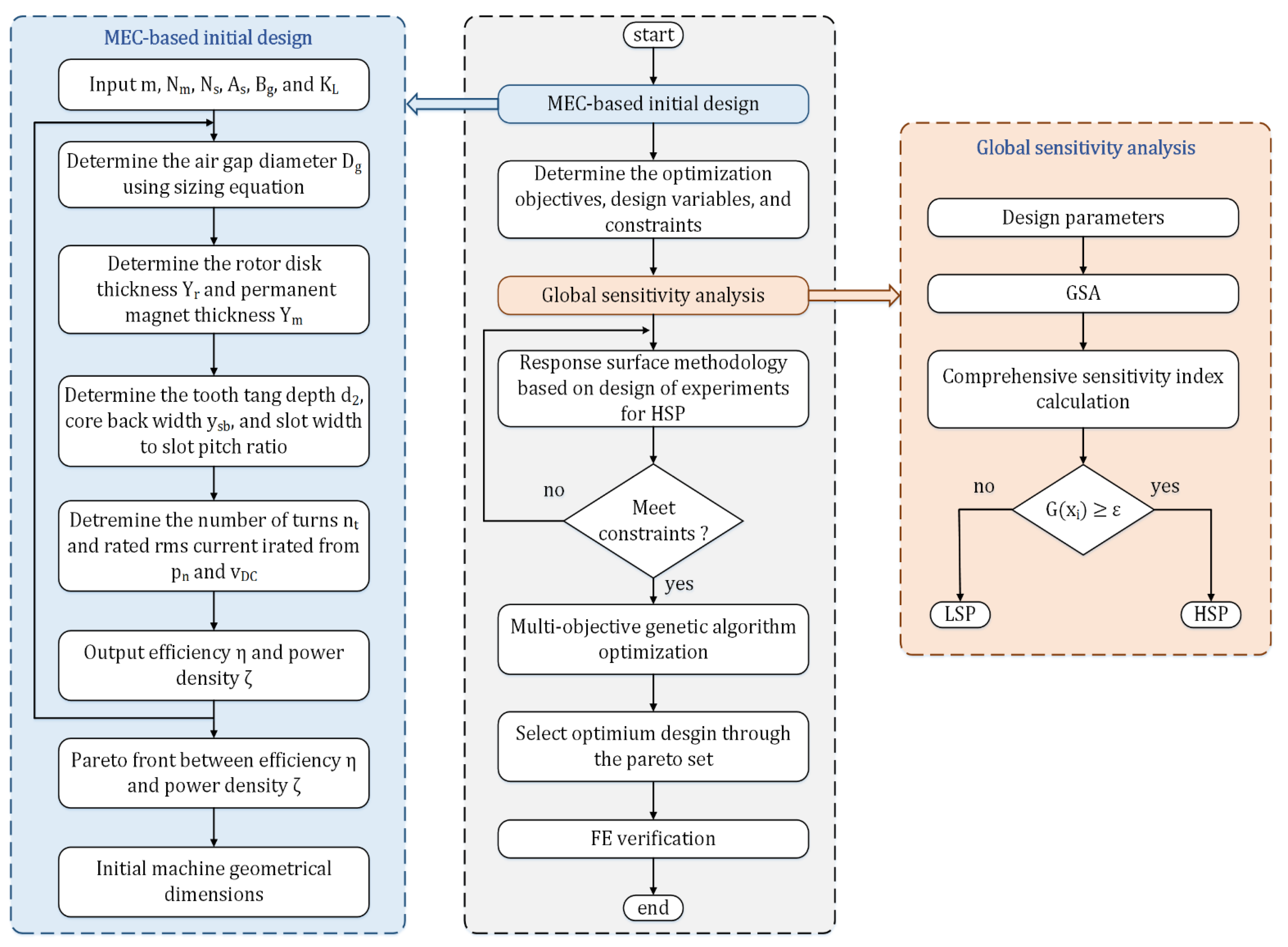
5. Overview of the Overall Design Optimization Process

This section describes the proposed design and optimization approach for obtaining the optimal SPM machine that can be used as the drivetrain element for EV on-board integrated chargers. First, the comprehensive sensitivity analysis technique is introduced, followed by a detailed description of the proposed approach’s main steps.

5.1. Comprehensive Sensitivity Analysis

Sensitivity analysis can effectively identify the influence of each design parameter on the various optimization performances of the SPM machine [13,25]. Sensitivity analysis based on functional decomposition of variance is adopted in this paper to show the effect of each design variable on the optimization objectives [10]. The variance-based sensitivity indices are obtained as in (5):
H ( X i ) = V a r [ E ( Y / X i ) ] V a r ( Y )
where the optimization output is defined as Y , the design parameters are defined as X i , and the average value of Y when X i is constant is defined as E ( Y / X i ) . V a r [ E ( Y / X i ) ] and V a r ( Y ) are the variances of E ( Y / X i ) and Y , respectively.
These indices express the share of variance of the optimization objective that is due to a given input ( X i ) so that the positive index means to increase the output and vice versa for the negative one. Moreover, the comprehensive sensitivity function with respect to the above-mentioned optimization goals can be achieved using (6):
G ( X i ) = λ 1 | H m e a n ( X i ) | + λ 2 | H r i p p l e p r o p ( X i ) | + λ 3 | H c o r e p r o p ( X i ) | + λ 4 | H r i p p l e c h a r g ( X i ) | + λ 5 | H c o r e c h a r g ( X i ) |
where H m e a n ( X i ) , H r i p p l e p r o p ( X i ) , H c o r e p r o p ( X i ) , H r i p p l e c h a r g ( X i ) , and H c o r e c h a r g ( X i ) are the sensitivity indices of the output torque, torque ripple in the propulsion, core losses in the propulsion, torque ripple in the charging, and core losses in the charging, respectively. The sensitivity indices, as well as the corresponding value of the comprehensive sensitivity function, are listed in Table 4. In Figure 5, the bar chart shows the comparison of all design variable indices on the five optimization goals. Therefore, the design parameters can be classified into high-sensitive parameters (HSP), which are bold in Table 4, and low-sensitive parameters (LSP) based on their significant effects. In that case, Y m , t s o / τ s o , and α P M constitute the HSP [ G ( X i ) >   0.3 ] , and the other design variables d 1 , Y s b , and W t are considered as the LSP [ G ( X i ) <   0.3 ] . Then, the significant design parameters will be optimized first.

5.2. Flowchart of the Design Optimization Approach

The flowchart of the design, together with the multi-objective optimization process, is shown in Figure 6. First, the initial machine design is obtained based on the MEC model, previously explained in Section 2. Then, according to the initial design, the optimization objectives, design variables, and boundary constraints are defined. After that, the selected design variables are categorized into HSP and LSP based on the comprehensive sensitivity analysis.
Furthermore, the response surface (RS) methodology is applied to HSP to illustrate the relationship between the optimization objectives and high-sensitive design parameters. The variation range of HSP is, therefore, refined. In addition, the multi-objective genetic algorithm (MOGA) is utilized to determine the optimal design point. Finally, a finite element (FE) model of the optimally-designed SPM machine is developed to validate the proposed optimization approach.

6. Multi-Objective Optimization Approach

In this paper, a multi-objective optimization approach is realized on the basis of a multi-objective genetic algorithm (MOGA) [26] to efficiently determine the optimal design point. The response surface (RS) methodology has been shown before to enhance the optimization efficiency [9].

6.1. Box–Behnken Response Surface Method

The RS methodology was shown to give considerable insight into how the optimization objectives vary with respect to the variation in key design variables [27]. Consequently, the RS method is adopted in this study to improve the variation range of HSP, which yields a reduction in the computational burden of the following MOGA-based optimization. In that case, Box–Behnken designs for RS methodology were developed with only 15 sampling points of the three high-sensitive variables. Accordingly, the three levels of the Box–Behnken designs need to be determined, which are −1, 0, and 1. From Table 3, the initial values of the key design parameters are adjusted as the central points (0), while the corner points (−1) and (1) are set based on the variation ranges.
The interacting influences of the five optimization performances with respect to the variation in the design variables Y m , t s o / τ s o and α P M are illustrated in Figure 7 and Figure 8. It can be noted that the optimization objectives cannot be achieved simultaneously. Taking the optimization objectives under charging (namely the peak-to-peak torque ripple and core losses) as an illustrative example, the reduction in the core losses is accompanied by a rise in the torque ripple, as shown in Figure 7e,f. Moreover, Figure 8e depicts the considerable reduction in the core losses with the increase in the PM thickness in the charging mode. Meanwhile, under propulsion, the higher the PM ratio, the higher the average torque production; however, the torque ripple also increases. In addition, the increase in the PM thickness yields a substantial rise in the average torque. In that case, the torque ripple is increased as well. Thus, an optimum trade-off between the various optimization targets needs to be defined.

6.2. Multi-Objective Genetic Algorithm (MOGA)

To avoid the inherent conflict between the optimization objectives, a MOGA-based optimization approach was utilized to define the optimal operating point, at which the optimum trade-off between the five objectives was realized. Not only the high-sensitive parameters but also the low-sensitive ones were optimized using the MOGA algorithm. It is worth mentioning that the corresponding parameters of the MOGA constitute objectives are: space dimension, 5; individuals for the population, 50; number of divisions for each dimension, 50; mutation probability, 0.2; and parameter used for crossover, 0.25. Moreover, the stopping criteria are either maximum number of generations, 100, or function tolerance, 1 e 4 . Figure 9 depicts the optimization results under both the propulsion and charging modes of operation. Thus, various design candidates were obtained. According to the design requirements of the EV charging application, the optimal design of the employed SPM machine, highlighted in green, can be determined, as shown in Figure 9.
Moreover, the optimal values of the selected optimization objectives, as well as the key design parameters, are listed in Table 5 and are quantitatively compared with the initial machine design obtained from the MEC model. Although both machines offer almost the same average torque production under propulsion, the peak-to-peak torque ripple and core losses are significantly curtailed when the optimal machine design is employed under various operational modes.

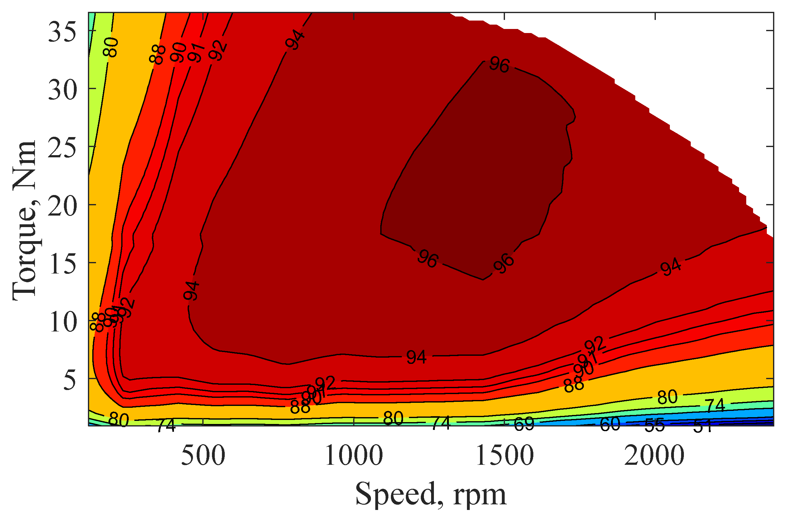
7. Finite Element Validation

In order to validate the results of the proposed MEC-based design optimization approach of an SPM machine in the charging process of EVs, FE simulations of both the optimal and initial designs were developed using the JMAGTM Designer 2D transient module. The two machines were assessed under both motoring and charging operational modes using the design parameters outlined in Table 2 considering the optimized values of the key design parameters listed in Table 5. Moreover, the results of the FE model were compared to the results obtained from the MEC model. Simulations of the two motors were carried out at the same speed of 1200 rpm.
Table 6 reveals the differences between the analytical and FE models with respect to the average torque production, the peak-to-peak torque ripple, RMS phase voltage, and core losses.
Figure 10 shows the torque profiles of the two machines under both operational modes. Under charging, the average torque production is nullified, which is the basic premise of the integrated OBC for EVs, as shown in Figure 10b. Despite the fact that the initial and optimal machines offer the same average torque under propulsion and zero average torque under charging, the peak-to-peak torque ripple is considerably reduced when the optimal machine is employed under both operational modes.
For example, the torque ripple notably decreases from 10.9 to 1.59 Nm when the initial and optimal machines are employed, respectively, in the motoring mode. During charging, the torque ripple reaches 0.78 Nm for the optimal machine, compared to 2.56 Nm obtained when the initial design is utilized.
Moreover, Figure 11 shows that both the initial and optimal machines have the same phase voltage profiles, i.e., same magnitude and frequency. Thus, similar average torque can be developed by the two motors at the same stator current in the propulsion mode, as shown in Figure 10a. The air-gap flux density of the two machines under both propulsion and charging operational modes is shown in Figure 12. Appropriate utilization of the PMs can be observed, since the value of the air-gap flux density approaches 1.0 T under both modes. Finally, good agreement between the FE and MEC-based analytical models with respect to the electromagnetic performances in both the initial and optimal designs can be noticed under the various operational modes.
The efficiency of the optimized machine with different operating conditions is shown in Figure 13. The optimal machine offers high efficiency at various operating points.

8. Conclusions

In this paper, an asymmetrical six-phase 12-slot/10-pole SPM machine is designed based on the MEC analytical model and optimized based on a multi-objective optimization approach under both the propulsion and charging modes of operation. A trade-off optimization design method among five design objectives (average output torque, torque ripple under propulsion, core losses under propulsion, torque ripple under charging, and core losses under charging) is efficiently achieved by using the response surface methodology and MOGA-based optimization. Both the theoretical findings and FE simulation results demonstrate the effectiveness of the proposed machine and the design optimization approach. Eventually, zero average torque production, lower peak-to-peak torque ripple, and lower core losses highlight the superiority of the optimized machine under the charging mode of operation when compared to the initial one.
From the perspective of optimization of PM machines, the proposed optimization approach can also be applicable to SPMs with different slot-pole combinations and other types of PM machines for torque improvement. Demagnetization capability and overall cost of PMs are also highly dependent on the geometrical dimensions of the employed machine. In the future, the authors will attempt to extend the proposed optimization approach for optimization of other performances, such as demagnetization capability and overall cost, so as to further verify its applicability and limitations.

Author Contributions

Conceptualization, A.H., A.S.A.-K. and M.Y.M.; methodology, A.H. and M.S.H.; software, A.H. and M.Y.M.; validation, M.S.H. and M.Y.M.; formal analysis, A.H., A.S.A.-K. and M.S.H.; investigation, M.S.H. and S.A.; resources, A.S.A.-K. and S.A.; data curation, A.H. and M.Y.M.; writing—original draft preparation, A.H., A.S.A.-K. and M.Y.M.; writing—review and editing, A.H., A.S.A.-K., M.Y.M., M.S.H. and S.A.; visualization, A.H. and A.S.A.-K.; supervision, A.S.A.-K. and S.A.; project administration, A.H., A.S.A.-K., M.S.H. and S.A.; funding acquisition, A.S.A.-K., M.S.H. and S.A. All authors have read and agreed to the published version of the manuscript.

Funding

This research received no external funding.

Institutional Review Board Statement

Not applicable.

Informed Consent Statement

Not applicable.

Data Availability Statement

Data are contained within the article.

Acknowledgments

This work was achieved by the financial support of ITIDAs ITAC collaborative funded project under the category type of advanced research projects (ARP) and Grant Number ARP2020.R29.7.

Conflicts of Interest

The authors declare no conflict of interest.

References

  1. Pescetto, P.; Pellegrino, G. Integrated Isolated OBC for EVs with 6-phase Traction Motor Drives. In Proceedings of the 2020 IEEE Energy Conversion Congress and Exposition (ECCE), Detroit, MI, USA, 11–15 October 2020; IEEE: Piscataway, NJ, USA, 2020; pp. 4112–4117. [Google Scholar]
  2. Metwly, M.Y.; Abdel-Majeed, M.S.; Abdel-Khalik, A.S.; Hamdy, R.A.; Hamad, M.S.; Ahmed, S. A Review of Integrated On-Board EV Battery Chargers: Advanced Topologies, Recent Developments and Optimal Selection of FSCW Slot/Pole Combination. IEEE Access 2020, 8, 85216–85242. [Google Scholar] [CrossRef]
  3. De Santiago, J.; Bernhoff, H.; Ekergård, B.; Eriksson, S.; Ferhatovic, S.; Waters, R.; Leijon, M. Electrical Motor Drivelines in Commercial All-Electric Vehicles: A Review. IEEE Trans. Veh. Technol. 2012, 61, 475–484. [Google Scholar] [CrossRef] [Green Version]
  4. Grunditz, E.A.; Thiringer, T. Performance Analysis of Current BEVs Based on a Comprehensive Review of Specifications. IEEE Trans. Transp. Electrif. 2016, 2, 270–289. [Google Scholar] [CrossRef]
  5. Bostanci, E.; Moallem, M.; Parsapour, A.; Fahimi, B. Opportunities and Challenges of Switched Reluctance Motor Drives for Electric Propulsion: A Comparative Study. IEEE Trans. Transp. Electrif. 2017, 3, 58–75. [Google Scholar] [CrossRef]
  6. Salem, A.; Narimani, M. A Review on Multiphase Drives for Automotive Traction Applications. IEEE Trans. Transp. Electrif. 2019, 5, 1329–1348. [Google Scholar] [CrossRef]
  7. El-Refaie, A.M. Fractional-Slot Concentrated-Windings Synchronous Permanent Magnet Machines: Opportunities and Challenges. IEEE Trans. Ind. Electron. 2010, 57, 107–121. [Google Scholar] [CrossRef]
  8. Hemeida, A.; Metwly, M.; Abdel-Khalik, A.; Ahmed, S. Optimal Design of A 12-Slot/10-Pole Six-Phase SPM Machine with Different Winding Layouts for Integrated On-Board EV Battery Charging. Energies 2021, 14, 1848. [Google Scholar] [CrossRef]
  9. Zhu, X.; Fan, D.; Xiang, Z.; Quan, L.; Hua, W.; Cheng, M. Systematic multi-level optimization design and dynamic control of less-rare-earth hybrid permanent magnet motor for all-climatic electric vehicles. Appl. Energy 2019, 253, 113549. [Google Scholar] [CrossRef]
  10. Yin, J.; Zhu, X.; Quan, L.; Zhang, C.; Xiang, Z. Comprehensive multi-objective scalarisation optimisation of a permanent magnet machine with correlation parameters stratified method. IET Electr. Power Appl. 2017, 11, 72–79. [Google Scholar] [CrossRef]
  11. Wang, D.; Wang, X.; Jung, S.-Y. Cogging Torque Minimization and Torque Ripple Suppression in Surface-Mounted Permanent Magnet Synchronous Machines Using Different Magnet Widths. IEEE Trans. Magn. 2013, 49, 2295–2298. [Google Scholar] [CrossRef]
  12. Zhu, X.; Wu, W.; Quan, L.; Xiang, Z.; Gu, W. Design and Multi-Objective Stratified Optimization of a Less-Rare-Earth Hybrid Permanent Magnets Motor With High Torque Density and Low Cost. IEEE Trans. Energy Convers. 2019, 34, 1178–1189. [Google Scholar] [CrossRef]
  13. Cao, D.; Zhao, W.; Ji, J.; Wang, Y. Parametric Equivalent Magnetic Network Modeling Approach for Multi-Objective Optimization of PM Machine. IEEE Trans. Ind. Electron. 2020, 68, 6619–6629. [Google Scholar] [CrossRef]
  14. Ding, L.; Liu, G.; Chen, Q.; Xu, G. A Novel Mesh-Based Equivalent Magnetic Network for Performance Analysis and Optimal Design of Permanent Magnet Machines. IEEE Trans. Energy Convers. 2019, 34, 1337–1346. [Google Scholar] [CrossRef]
  15. Tiegna, H.; Amara, Y.; Barakat, G. Overview of analytical models of permanent magnet electrical machines for analysis and design purposes. Math. Comput. Simul. 2013, 90, 162–177. [Google Scholar] [CrossRef]
  16. Cao, D.; Zhao, W.; Ji, J.; Ding, L.; Zheng, J. A Generalized Equivalent Magnetic Network Modeling Method for Vehicular Dual-Permanent-Magnet Vernier Machines. IEEE Trans. Energy Convers. 2019, 34, 1950–1962. [Google Scholar] [CrossRef]
  17. Pluk, K.J.W.; Jansen, J.W.; Lomonova, E.A. 3-D Hybrid Analytical Modeling: 3-D Fourier Modeling Combined With Mesh-Based 3-D Magnetic Equivalent Circuits. IEEE Trans. Magn. 2015, 51, 8208614. [Google Scholar] [CrossRef]
  18. Hemeida, A.; Lehikoinen, A.; Rasilo, P.; Vansompel, H.; Belahcen, A.; Arkkio, A.; Sergeant, P. A Simple and Efficient Quasi-3D Magnetic Equivalent Circuit for Surface Axial Flux Permanent Magnet Synchronous Machines. IEEE Trans. Ind. Electron. 2018, 66, 8318–8333. [Google Scholar] [CrossRef]
  19. Abdel-Khalik, A.S.; Ahmed, S.; Massoud, A.M. Performance Evaluation of an On-Board Integrated Battery Charger System Using a 12-Slot/10-Pole Surface-Mounted PM Propulsion Motor. In Proceedings of the 2017 9th IEEE-GCC Conference and Exhibition (GCCCE), Manama, Bahrain, 8–11 May 2017. [Google Scholar]
  20. Subotic, I.; Bodo, N.; Levi, E. Integration of Six-Phase EV Drivetrains Into Battery Charging Process With Direct Grid Connection. IEEE Trans. Energy Convers. 2017, 32, 1012–1022. [Google Scholar] [CrossRef] [Green Version]
  21. Subotic, I.; Bodo, N.; Levi, E.; Dumnic, B.; Milicevic, D.; Katic, V. Overview of fast on-board integrated battery chargers for electric vehicles based on multiphase machines and power electronics. IET Electr. Power Appl. 2016, 10, 217–229. [Google Scholar] [CrossRef]
  22. Bertotti, G. General properties of power losses in soft ferromagnetic materials. IEEE Trans. Magn. 1987, 24, 621–630. [Google Scholar] [CrossRef]
  23. Wang, J.; Yuan, X.; Atallah, K. Design Optimization of a Surface-Mounted Permanent-Magnet Motor With Concentrated Windings for Electric Vehicle Applications. IEEE Trans. Veh. Technol. 2012, 62, 1053–1064. [Google Scholar] [CrossRef]
  24. Ma, C.; Qu, L. Multiobjective Optimization of Switched Reluctance Motors Based on Design of Experiments and Particle Swarm Optimization. IEEE Trans. Energy Convers. 2015, 30, 1144–1153. [Google Scholar] [CrossRef] [Green Version]
  25. Zhu, X.; Shu, Z.; Quan, L.; Xiang, Z.; Pan, X. Multi-Objective Optimization of an Outer-Rotor V-Shaped Permanent Magnet Flux Switching Motor Based on Multi-Level Design Method. IEEE Trans. Magn. 2016, 52, 8205508. [Google Scholar] [CrossRef]
  26. Martínez-Iranzo, M.; Herrero, J.M.; Sanchis, J.; Blasco, X.; García-Nieto, S. Applied Pareto multi-objective optimization by stochastic solvers. Eng. Appl. Artif. Intell. 2009, 22, 455–465. [Google Scholar] [CrossRef]
  27. Zhu, X.; Xiang, Z.; Quan, L.; Chen, Y.; Mo, L. Multimode Optimization Research on a Multiport Magnetic Planetary Gear Permanent Magnet Machine for Hybrid Electric Vehicles. IEEE Trans. Ind. Electron. 2018, 65, 9035–9046. [Google Scholar] [CrossRef]
Figure 1. Asymmetrical six-phase integrated battery charger schematic and phasor diagrams: (a) configuration; (b) phasor diagram under propulsion; (c) phasor diagram under charging.
Machines 09 00329 g001
Figure 2. MEC subdivision principle for RFPMSM.
Machines 09 00329 g002
Figure 3. Motor topology: (a) 2D configuration; (b) parametric model.
Machines 09 00329 g003
Figure 4. MMF harmonic spectra per unit current: (a) under propulsion; (b) under charging.
Machines 09 00329 g004
Figure 5. Sensitivity analysis results.
Machines 09 00329 g005
Figure 6. Flowchart of the design and multi-objective optimization process.
Machines 09 00329 g006
Figure 7. Response surface results of various optimization objectives versus t s o / τ s o and α P M : (a) average torque under propulsion; (b) torque ripple under propulsion. (c) core losses under propulsion; (d) torque ripple under charging; (e) core losses under charging.
Machines 09 00329 g007
Figure 8. Response surface results of various optimization objectives versus t s o / τ s o ; and Y m : (a) average torque under propulsion; (b) torque ripple under propulsion; (c) core losses under propulsion; (d) torque ripple under charging; (e) core losses under charging.
Machines 09 00329 g008
Figure 9. MOGA-based optimization results of the five optimization objectives under various operational modes: (a) propulsion; (b) charging.
Machines 09 00329 g009
Figure 10. Torque profiles under various operational modes: (a) propulsion; (b) charging.
Machines 09 00329 g010
Figure 11. Phase voltage profiles under various operational modes: (a) propulsion; (b) charging.
Machines 09 00329 g011
Figure 12. Air-gap flux density under various operational modes: (a) propulsion; (b) charging.
Machines 09 00329 g012
Figure 13. Efficiency map.
Machines 09 00329 g013
Table 1. SPM machines design specifications.
e-Golf Requirements
Rated power (kW)5
Rated speed (rpm)1200
Maximum speed (rpm)10,500
Rated torque (Nm)39.8
Line current peak value (A) 5.9
DC link voltage (V)600
Table 2. SPM machine parameters.
ParameterSymbolValue
Stator outer diameter (mm) D s o 231.4
Stator inner diameter (mm) D s i 155
Stack length (mm) L e f f 84
Air gap length (mm) g 1
Depth of stator slot (mm) d s s 22.5
Slot-opening width (mm) t s o 9.06
Rotor outer diameter (mm) D r o 153
Shaft diameter (mm) D s h a f t 111.8
Rotor disc thickness (mm) Y r 15.4
Gap between magnets (mm) d p m 5.59
No. of turns per coil N t 80
Rated RMS current (A) I a 4.1676
Phase resistance (Ω) R 0.03988
Table 3. Design parameters initial value and variation range.
ParameterSymbolInitialRange
Magnet thickness (mm) Y m 42.5–5.5
Tooth-tang depth (mm) d 1 6.75.5–7.9
Core back width (mm) Y s b 14.313–16
Tooth width (mm) W t 26.5121.17–31.78
Slot-opening ratio t s o / τ s o 0.150.05–0.44
PM width to pole pitch ratio α P M 0.950.5–0.95
Table 4. Comprehensive sensitivity analysis indices.
Item H m e a n H r i p p l e p r o p H c o r e p r o p H r i p p l e c h a r g H c o r e c h a r g G ( X i )
Y m 0.16270.03720.10030.01340.61680.3269
d 1 0.0160−0.0046−0.00440.00720.02590.0207
Y s b 0.0183−0.00200.01710.01450.02840.0280
W t 0.0107−0.00400.09160.00520.02630.0440
t s o / τ s o −0.19320.29320.26360.15790.04090.3139
α P M 0.73790.45950.59430.03640.16510.6818
Table 5. Optimal SPM machine results.
Variable/ObjectiveInitialOptimal
Y m 45.2
d 1 6.76.8
Y s b 14.315.7
W t 26.5129.23
t s o / τ s o 0.150.21
α P M 0.950.88
T m e a n 42.7 Nm42.73 Nm
T r i p p l e p r o p 10.9 Nm1.59 Nm
P c o r e p r o p 64.77 W56 W
T r i p p l e c h a r g 2.56 Nm0.78 Nm
P c o r e c h a r g 2.53 W1.99 W
Table 6. Comparison of FE and analytical models.
Initial MachineOptimal Machine
OutputPropulsionChargingOutputPropulsionCharging
JMAGMECJMAGMECJMAGMECJMAGMEC
T a v g   ( N m ) 4342.700 T a v g   ( N m ) 42.7742.7300
T r i p p l e   ( N m ) 12.210.92.642.56 T r i p p l e   ( N m ) 1.891.5910.78
r m s   V p h   ( V ) 219.521811.5712.62 r m s   V p h   ( V ) 22322210.9511.64
P c o r e   ( W ) 65.364.772.312.53 P c o r e   ( W ) 54.5562.351.99
Publisher’s Note: MDPI stays neutral with regard to jurisdictional claims in published maps and institutional affiliations.

