Article

Algorithm for Compression Design Allowable Determination of Composite Laminates with Initial Delaminations

1
School of Aeronautic Science and Engineering, Beihang University, Beijing 100191, China
2
Aircraft and Propulsion Laboratory, Ningbo Institute of Technology, Beihang University, Ningbo 315100, China
3
Key Laboratory of Bio-Inspired Smart Interfacial Science and Technology of Ministry of Education, School of Chemistry, Beihang University, Beijing 100191, China
*
Author to whom correspondence should be addressed.
Machines 2021, 9(12), 307; https://doi.org/10.3390/machines9120307
Submission received: 28 October 2021 / Revised: 13 November 2021 / Accepted: 22 November 2021 / Published: 24 November 2021

Abstract

:
With the increasing demands for detailed design of composite aircraft structures, the method of covering all damages with low design allowables cannot meet the current requirements for aircraft structure design. Herein, this paper proposes a novel algorithm for design allowable determination of composite laminates by combining the damage distribution with damage factor model of design allowable, so as to provide different structures with more accurate design allowables based on their initial damages. For the composite laminates with initial delaminations, a model describing the effect of delamination size and depth position on the compression design allowable is developed and the compression design allowable of different aircraft structures are individually determined by employing abundant initial delamination statistics. Compared with the design allowable offered by the single-point method, the design allowable based on the initial damage can be increased by at least 5% to 20%, greatly improving the economic benefits of the aircraft structures and providing an important support for the damage tolerance design of the composite structures.

1. Introduction

Serving as the threshold of actual stress/strain, the design allowable plays a vital role in ensuring the safety and reliability of composite aircraft structures [1,2,3]. The aeronautical industry usually applies the A/B-basis value of the material properties as the design allowable of composites laminates. To obtain the statistical distributions of material properties such as the strength or failure strain, a sufficient number of coupons at the same configuration need to be tested, leading to a costly and time-consuming process.
Among the basis value estimation methods, the single-point method proposed by MIL-HDBK-17F [4] is the most widely used approach to generating the design allowables, which assumed that the strength of each specimen at the same configuration is conform a common distribution and the distribution can be approximated when a sufficient number of tests have been carried out. Based on the single-point method, a regression analysis based pooling method was reported by CMH-17 [5] to merge multiple condition samples through checking the inter-assay variability.
In order to reduce the time and economic costs associated with considerable experimental tests, analytical [6,7] and numerical [8,9,10,11,12] simulation have become important alternative options for estimating the design allowables. For example, Vallmajó et al. [6] predicted the B-basis design allowable of notched composite laminates by utilizing an analytical model and considering the variability of material properties and specimen geometry. Cózar et al. [9] proposed a method to obtain the design allowables of the compression after impact (CAI) strength, which combined high-fidelity FE simulations to model the progressive degradation and failure of composites, local sensitivity analysis to identify the key parameters, response surface methodology to construct the correlation between the key parameters and CAI strength, and Monte Carlo simulation to propagate the uncertainty of the parameters. Moreover, to provide further reduction of the computational time, machine learning algorithms were employed by Furtado et al. [7] to analyze the uncertainty propagation from input parameters including material properties and geometric features to the open-hole strength. In terms of the strength distribution, the B-basis values of the open-hole strength is eventually estimated.
However, these studies mainly performed statistical analysis on the single-state data (the results of the same type of test) to generate the design allowable values, which implies that the worst environmental conditions and the most dangerous defects are taken into account, leading to a conservative design allowable. Therefore, an algorithm based on multi-state data that can provide individual design allowables for composite structures according to their actual damage distribution or environmental conditions is of great necessity.
For the compressive load cases, the design allowable mainly generates based on the test data of specimens with impact damage [1,9], which can result in matrix cracking, delamination and fiber breakage of the laminates [13]. Among these damage modes, delamination plays the dominant role in CAI loading event [14,15] and becomes a key influencing factor of compression design allowable. Recently, a number of studies dedicated to understanding the delamination effect on the compressive behavior and ultimate strength of composite laminates have been carried out. İpek et al. [16] experimentally analyzed the effects of delamination size and through-thickness position on the buckling behavior of the laminated composites. Their results revealed that the critical buckling loads decrease as the delamination size increases, and the shallower delamination causes a greater reduction in the critical buckling load. Kharghani at al. [17] utilized the Layerwise Higher Order Shear Deformation Theory to predict the ultimate strength of composite laminates with different types of delaminations and reported that the depth of through-width delamination significantly affects the ultimate strength. However, in practice, multiple delaminations often appear in the laminates, rather than a single one. For this reason, Aslan and Sahin [18] performed an experimental and numerical investigation on the effects of delamination sizes on the buckling and compressive failure load of composite laminates containing multiple delaminations. It was found that the critical buckling load of composite laminates are mainly affected by the longest and near-surface delamination size. Jin et al. [19] substituted the multi-delamination region by a sub-laminate having same dimensions and stacking sequences but with reduced stiffness to analyze the bulking behavior of the composite laminates.
In this study, a strategy for design allowable determination based on multi-state data is proposed. This procedure explores the intrinsic relationship between the results of experiments with different configurations and establishes a factor model for assessing the influence of damage size and location on the design allowable. For composite laminates with delamination, a response model considering the effect of delamination on the compression design allowable is established, where the effect of delamination size and depth position is quantified. In this condition, structures that are highly threatened by foreign impact can adopt a more conservative design allowable, while the structures facing less threat of impact are able to employ a larger design allowable. It can be foreseen that this will greatly boost the design allowables, which will facilitate the detailed design of the composite structures and improve the economic benefits while ensuring the safety and reliability.
This paper is organized as follows. Section 2, the distributions of delamination size in several composite aircraft structures are investigated, and the most dangerous delamination deficiencies are estimated. Section 3 performs static compression tests on the composite laminates embedded with delamination. Section 4 establishes a factor model to characterize the influence of delamination size and depth position on the compression failure strain and determines the compression design allowable of different composite structures with their initial damages. Finally, in Section 5, there is a conclusion.

2. Statistical Analysis of Delamination

As a predominant form of deficiency during fabrication and service, delamination exhibits uncertainty and distribution characteristics in terms of delamination size and depth position. For different composite structures, the delaminations may follow completely distinct distributions, resulting in diverse initial delaminations should be taken into account when determining design allowables. Therefore, a better understanding of the delamination distribution of composite aircraft structures will be of great benefit to the composite structure design.

2.1. Distribution Fitting of Delamination Size

In this section, a total of 281 delamination data caused by manufacturing defects are considered. These data were collected by the composite testing technology center of AVIC Composite Co., Ltd. from four composite aircraft structures by using ultrasonic C-scan technique when leaving the factory. The structures considered involve the wing skin, wing rib, horizontal tail skin, and horizontal tail rib. The statistical results demonstrate that more than 90% of the delaminations are located in the depth position of h / 4 , h / 3 , and h / 2 , where h represents the thickness of the laminates. And it was also shown that more than 80% of the delaminations are smaller than 25.4 mm, less than 15% are between 25.4 mm and 50 mm, and only about 5% are larger than 50 mm. It should be mentioned that due to the diverse shapes of actual delaminations, the delamination considered in this paper is uniformly modelled as a circular delamination, and the delamination size is defined as the diameter, which is the average of the maximum length and width of delamination detected during manufacturing and service. In order to describe and characterize the distribution of delamination size, the Weibull, normal and lognormal distributions were selected for the study.
The probability density function (PDF) of the two-parameter Weibull distribution is expressed as
f ( D ; α , β ) = { β α ( D α ) β 1 exp [ ( D α ) β ] D > 0 0 D 0
where α and β are the scale and shape parameters, respectively, which can be calculated by the maximum-likelihood method,
{ n β ^ α ^ + β ^ α ^ β ^ + 1 i = 1 n D i β ^ = 0 n β ^ n ln α ^ + i = 1 n ln D i i = 1 n [ ( D i α ^ ) β ^ ( ln D i ln α ^ ) ] = 0
where the hat ‘’ ^ ’’ indicates the estimation of the variable.
The PDF of normal distribution is given by
f ( D ; μ , σ ) = 1 2 π σ exp [ ( D μ ) 2 / 2 σ 2 ]
where μ and σ 2 can be estimated by
{ μ ^ = 1 n i = 1 n D i σ 2 ^ = 1 n i = 1 n ( D i μ ^ ) 2
And the PDF of lognormal distribution is described as
f ( D ; μ , σ ) = { 1 2 π σ D exp [ ( ln D μ ) 2 / 2 σ 2 ] D > 0 0 D 0
Similar to the normal distribution, the parameters can be obtained with:
{ μ ^ = 1 n i = 1 n ln D i σ 2 ^ = 1 n i = 1 n ( ln D i μ ^ ) 2
The maximum likelihood estimates of these parameters are listed in Table 1 and Figure 1 plots the cumulative distribution functions (CDF) of the delamination sizes. As can be seen, the CDF curves of the lognormal distributions are much closer to the empirical cumulative distribution function (ECDF) curves of the data than those of other distributions.

2.2. Goodness-of-Fit Test

Anderson–Darling (A–D) test, which is sensitive to discrepancies in the tail regions, is employed to determine whether the chosen distributions should be statistically accepted [20]. The Anderson–Darling test is defined as:
H 0 : The delamination size data follow the specific distribution; and
H 1 : The delamination size data do not follow the specific distribution.
The A–D test statistic is defined as
A 2 = n i = 1 n 2 i 1 n [ ln ( F ( D i ) ) + ln ( 1 F ( D n + 1 i ) ) ]
where n is the sample size, F ( · ) is the CDF of the specific distribution, and D i are the ordered data of delamination size. Then the p -value can be calculated with A 2 . The test will reject the null hypothesis when the p -value is less than or equal to the significance level of 0.05. In addition, coefficients of determination R 2 are calculated to make an intuitionistic comparison between the proposed distributions. Summarized in Table 1, the test results and R 2 -values of the hypothesized distributions indicate that the delamination data of the considered structures are all in excellent agreement with the lognormal distribution.

2.3. Initial Damage

To represent the most dangerous delamination that may emerge in the composite structures, the upper one-sided confidence bound of population percentile of delamination size is calculated, defined as the initial damage D R U , that is,
Pr { D R D } = R
Pr { D R U D R } = γ
where D R presents the 100 R t h percentile values of delamination size distribution, R and γ are the reliability and confidence level, respectively.
Since the delamination size datasets come from populations with lognormal distributions, the initial damage D R U is denoted as
D R U = exp ( μ + k σ )
where μ and σ are the model parameters of the lognormal distribution, and k is the one-sided tolerance-limit factor, which depends on the sample size, reliability and confidence [21]. A numerical approximation to k value is given as
k = 2 n 3 2 n 4 ( t R + t γ 1 n ( 1 t γ 2 w ) + t R 2 w ) ( 1 t γ 2 w ) 1
w = 2 ( n + t γ 1.645 1 n + t γ 1.645 )
where n is the sample size, t R = Φ 1 ( R ) and t γ = Φ 1 ( γ ) are the standard normal deviator, and Φ ( ) is the CDF of the standard normal distribution.
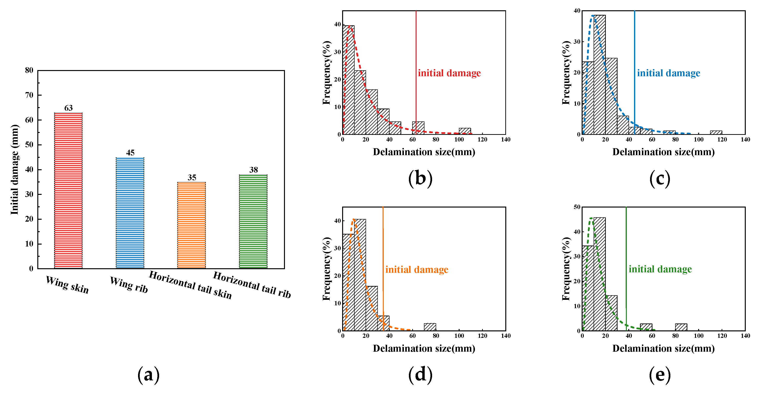
In this study, the initial damages with reliability of 90% and confidence of 95% of different composite aircraft structures are illustrated in Figure 2. As shown in the figure, the initial damage varies widely from structure to structure, ranging from 35 to 63 mm.

3. Experimental Study

Literature has revealed that the presence of delamination significantly decreases the compression carrying capacity of the composite laminates [16,17,22,23]. However, few researchers statistically investigate the effect of the delamination on the compression failure strain, which is related to the design allowable. In this study, static compression tests were conducted on composite laminates embedded with different kinds of delaminations and a phenomenological model was proposed to characterize the effect of delamination size and depth position on the compression failure strain.

3.1. Material and Specimen

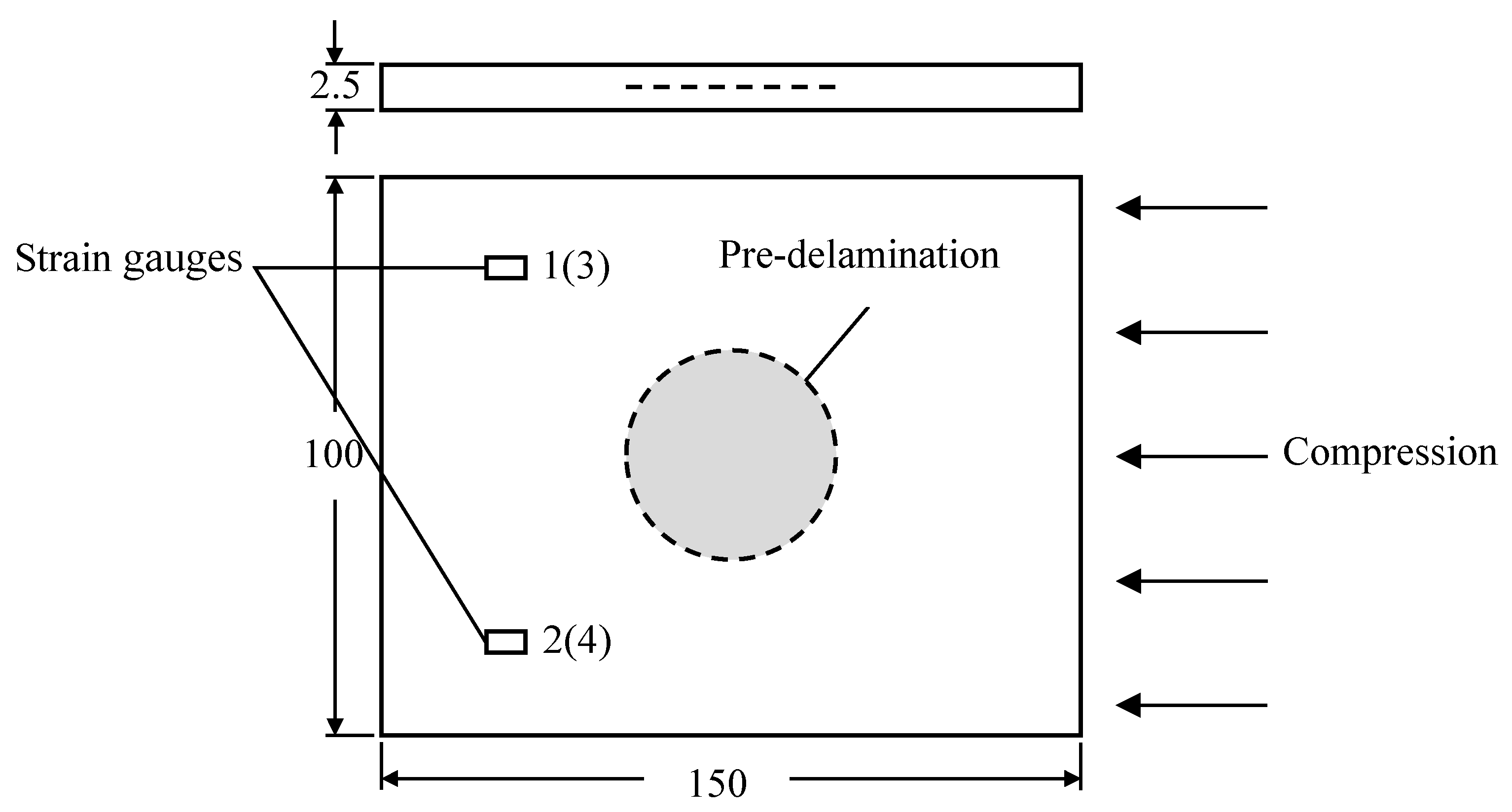
ZT7H carbon fiber and 5429 bismaleimide resin prepregs were used to manufacture the tested specimens and the stacking sequence of laminates was set as [-45/0/45/90/0/0/-45/90/45/0]S. During stacking, a single 100 microns PTFE circular film was placed within the two specific prepreg tapes to introduce the delamination deficiency. As shown in Table 2, 25 mm, 38 mm, and 50 mm were selected to be the diameter of the delamination, and the depth position of delamination was either h / 2 or h / 3 . The dimension of specimen for the compression tests was obtained as 150 mm × 100 mm × 2.5 mm (see Figure 3).

3.2. Compression Test

The static compression tests were performed on an INSTRON 8804 universal testing machine, following the ASTM D7137/D7137M standard [24]. Four strain gauges were attached on both sides of the specimen to monitor the compression strain, so as to keep the percent bending within a small range. In the tests, the compression failure strain were obtained when the force decreases from approximately 30% from maximum in the stress-strain curves. Moreover, the compression failure strain of laminate without delamination was also measured, according to the ASTM D6641/D6641M standard [25].

4. Results and Discussion

4.1. Effects of Delamination Size and Depth Position

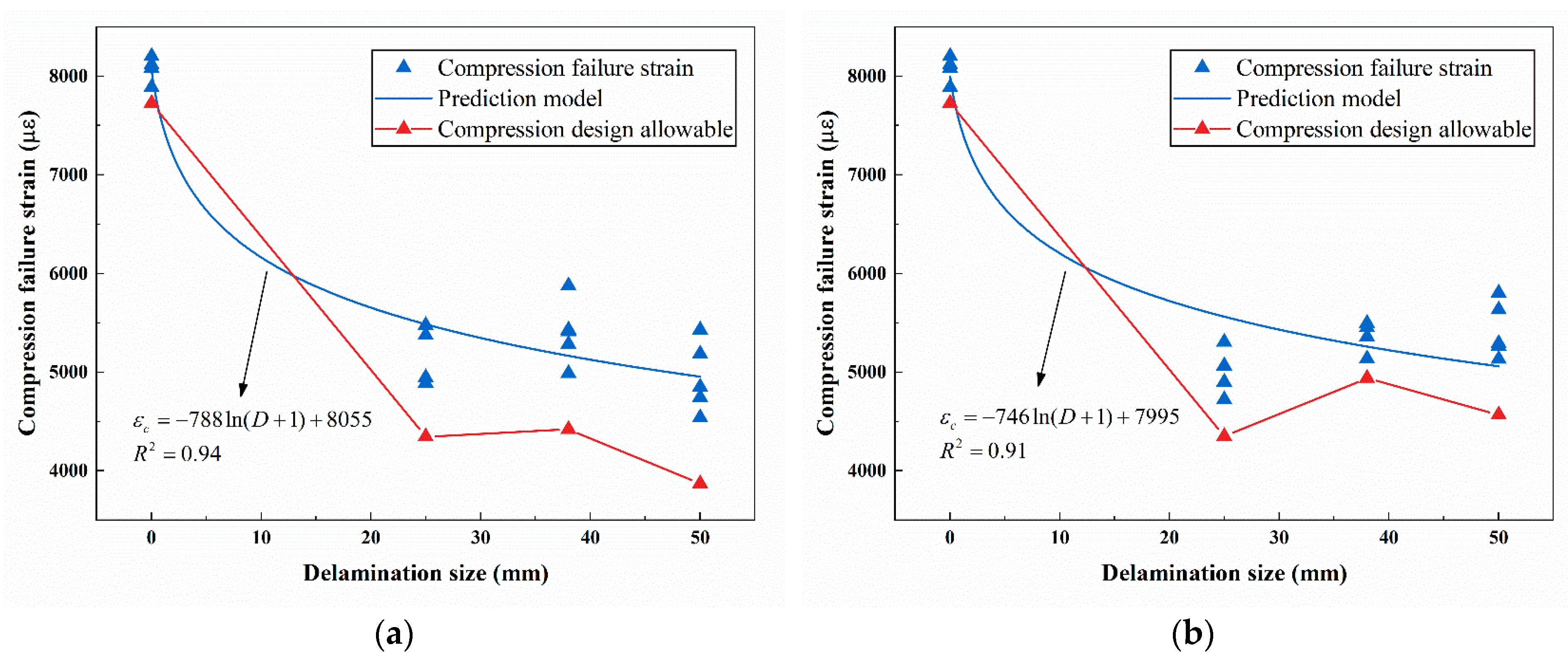
The compression failure strains of the laminates with delamination in h / 3 and h / 2 are shown in Figure 4. It can be seen that the presence of delamination significantly reduce the compression carrying capability of laminates, since the compression failure strain decreases by more than 35% as the delamination size increases from 0 to 25 mm. However, there is no major difference between the compression failure strains when the delamination size is larger than 25 mm. A logarithm prediction model is established for phenomenological description,
ε c = A ln ( D + 1 ) + B + ε
where ε c is the compression failure strain, D is the delamination size, A , B are the model parameters which can be estimated through linear regression, and ε is a random variable with zero expectation characterizing the stochastic nature of composites. From Equation (13), it can be known that when D = 0 , ε ^ c = B , representing the compression failure strain of the laminates without delamination.
In the structure design of aircraft, the design allowables are often determined with the A/B-basis values. Assuming that the compression failure strain datasets are all from populations with normal distributions, then the compression design allowable ε p can be given by the single-point method,
ε p = ε ¯ c k B s
where ε ¯ c and s are the mean and standard deviation of the experimental data, respectively, and k B is the one-sided tolerance-limit factor calculated with Equation (11), where R = 90 % and γ = 95 % . As shown in Figure 4, the design allowable obtained by the conventional method fluctuates due to the interaction of the mean and dispersion of the sample.
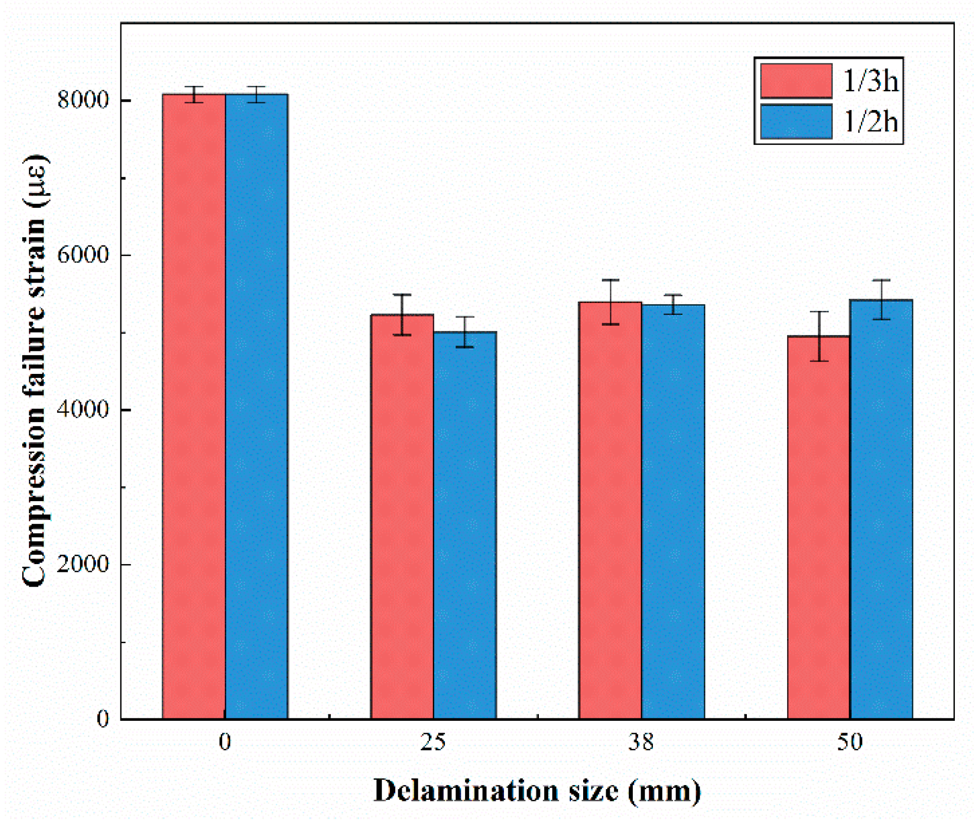
Literature has shown that the upper delamination depth position has a negative effect on the compression bearing capacity of the laminate [16,26]. However, the experiment results of this study shows that the compression failure strains of these two positions are of little difference (see Figure 5). This may be mainly because the depth position considered does not alter the buckling behavior and the buckling remains a closing mode shape (the midpoints of two sub-laminates moving in same direction), thus the critical loads did not changed significantly. If the delamination is closer to the surface, the midpoints of two sub-laminates may move in reverse, and the critical loads may decrease greatly [27].

4.2. Compression Failure Strain Estimation

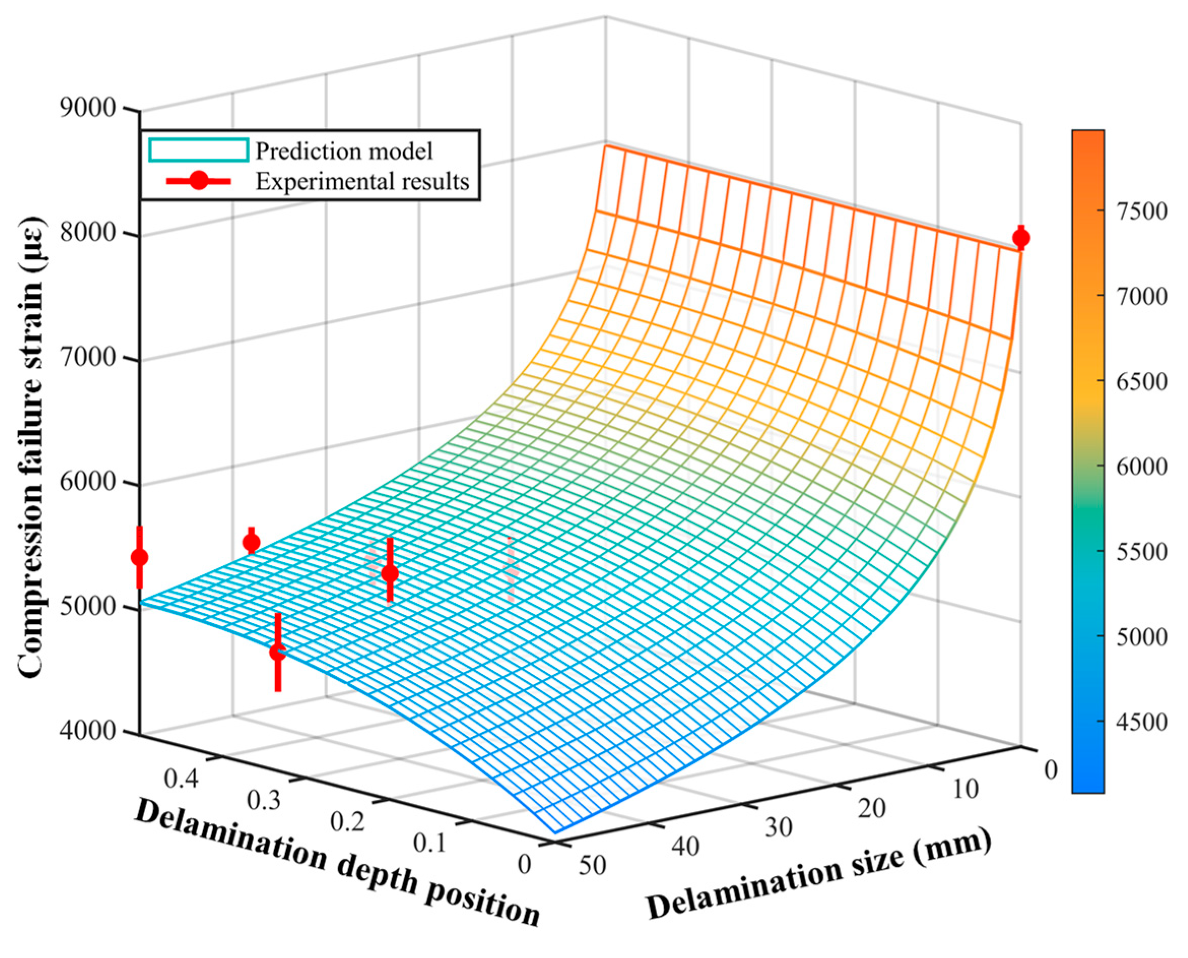
By comparing the prediction models shown in Figure 4, it can be found that the failure strain is more sensitive to the variation of delamination size when the delamination is near the surface. Based on the Equation (13), the compression failure strain prediction model is updated to
ε c = A e m ( H 0.5 ) 2 ln ( D + 1 ) + B + ε
where H presents the relative depth position of delamination, [ A e m ( H 0.5 ) 2 ln ( D + 1 ) ] characterizes the reduction of compression failure strain caused by delamination, and D = 0 indicates no delamination. With the item “ ( H 0.5 ) 2 ”, the depth positions that are symmetrical about the middle layer have the same effect on the failure strain. It also should be mentioned that H only makes sense in some specific values to imply that the delamination is located in two specific prepreg tapes, that is, H = i / N , where i = 1 , 2 , , N 1 and N is the number of layers.
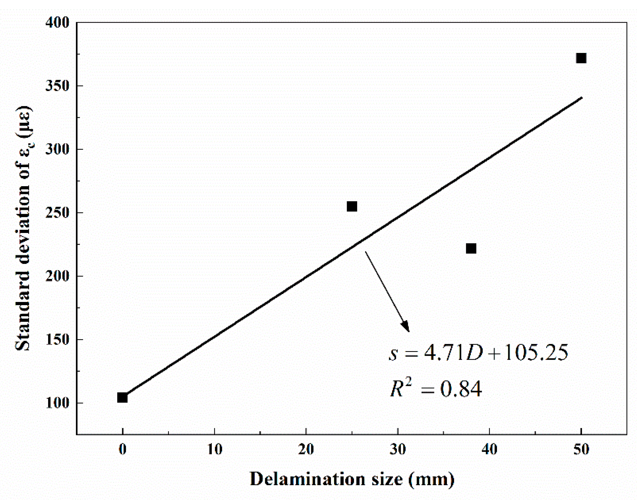
In addition, a linear correlation between the standard deviation of ε c and the delamination size D is found (see Figure 6), which can be described as
s = a D + b
where s is the sample standard deviation, a , b are the model parameters. Involving such variation of variance in estimating the model parameters will be beneficial to improving the estimation accuracy.
Due to the model nonlinearity and variable variance, the extended Kalman filter (EKF) [28], which has numerous applications in nonlinear estimation, is employed to recursively estimate the parameters in Equation (15).
In this study, the system state x k is composed of the model parameters, that is, x k = [ x 1 x 2 x 3 ] T = [ A m B ] T . And the dynamic state-space model studied is
x k = x k 1 + w k 1
y k = h k ( x k ) + v k
where y k = ε c , k is the measurement, w k , v k are the perturbation sources with covariance of Q k and R k = s 2 , respectively, and h k ( x 1 , x 2 , x 3 ) is a nonlinear function, that is, h k ( x 1 , x 2 , x 3 ) = ln ( D k + 1 ) x 1 [ exp ( ( H k 0.5 ) 2 ) ] x 2 + x 3 .
In EKF, linearization is performed on the measurement equation by Taylor expansion, and the system state is estimated the by minimizing the square sum of a posteriori estimation errors. The derivation of EKF algorithm is attached in the Appendix A and the complete specification for the EKF for parameter estimation is shown in Algorithm 1.
Algorithm 1. EKF for Parameter Estimation.
Initialize with:
x ^ 0 + = E ( x 0 )
P 0 + = E [ ( x 0 x ^ 0 + ) ( x 0 x ^ 0 + ) T ]
For   k { 1 , 2 , , n } ,
Time update:
x ^ k = x ^ k 1 +
P k = P k 1 +
Linearization:
H k = h k x | x ^ k
Measurement update:
K k = P k H k T ( H k P k H k T + R k ) 1
x ^ k + = x ^ k + K k [ y k h k ( x ^ k , 0 ) ]
P k + = ( I K k H k ) P k ( I K k H k ) T + K k R k K k T
In Algorithm 1, E ( ) represents the expectations of the variables, P k and P k + are the prior and posteriori error covariance, respectively, H k is the partial derivative of h k ( x k ) with respect to x k , K k denotes the gain matrix determined by minimizing the summary of variances of the estimations errors, and I is the unit matrix. Table 3 demonstrates the estimates and errors of the model parameters.
From Figure 7, it can be seen that the prediction model of compression failure strain is able to fit the experimental samples with good accuracy.

4.3. Compression Design Allowable Determination

The compression design allowables are obtained according to the B-basis value of the compression failure strain. Assuming that the experimental data is from a population with a normal distribution, then the B-basis compression design allowable value can be given as
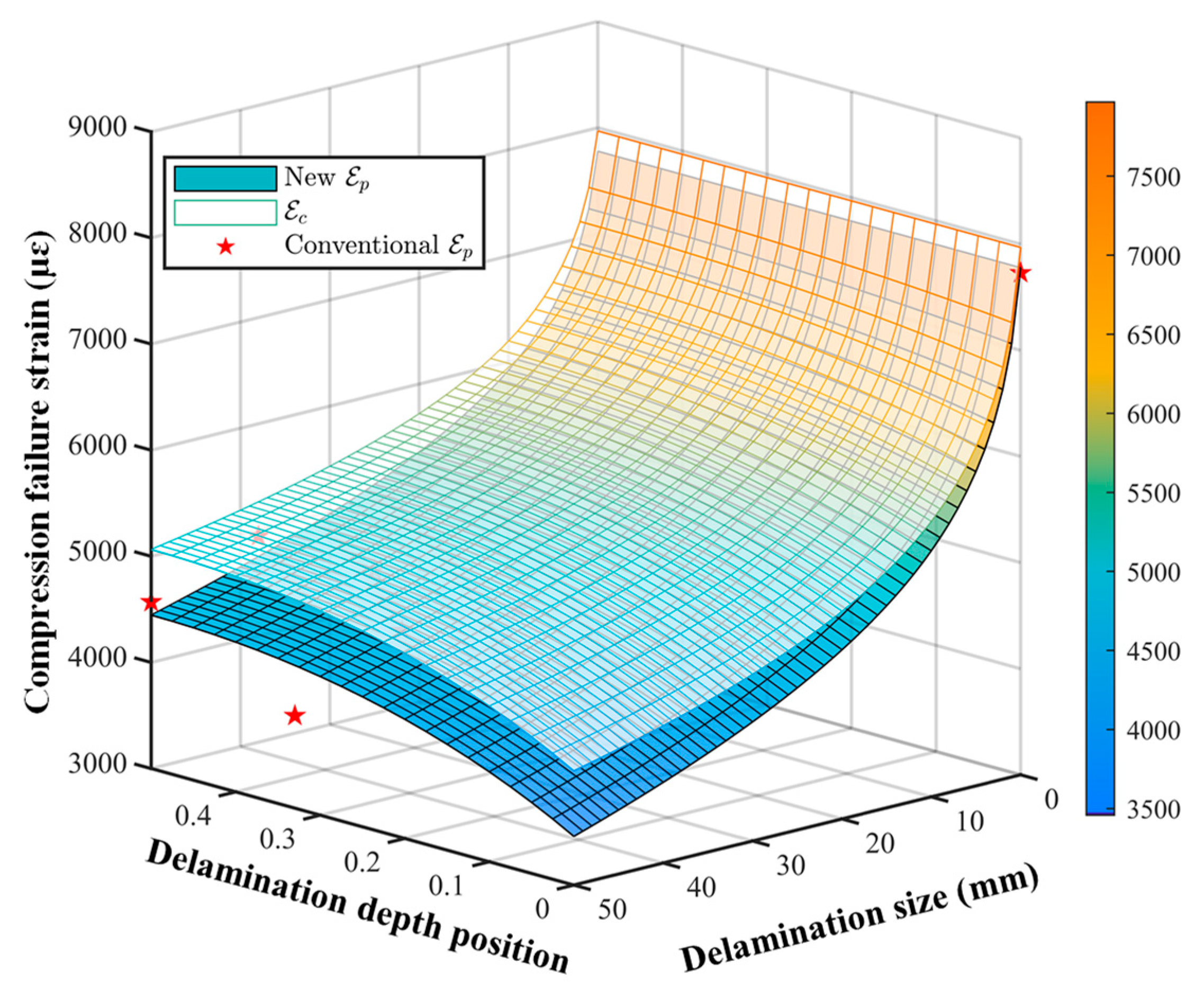
ε p = ε ^ c k B s = A e m ( H 0.5 ) 2 ln ( D + 1 ) + B k B s
where ε ^ c is the compression failure strain estimated by Equation (15), k B is the tolerance factor, s is the sample deviation presented in Equation (16). According to the above expression, the compression design allowable surface is demonstrated in Figure 8.
The design allowable surface serves two purposes: it can determine the compression design allowable based on the damage distributions of composite structures; and it is able to estimate the damage thresholds when the design allowables are defined so as to provide references for the composite structures maintenance. For example, assuming that the aircraft structures presented in Section 2 are manufactured with the composites laminate tested, then their compression design allowables can be obtained under the input of the initial damages. Due to the large proportion and serious harmfulness, the initial damages take h / 4 as their depth positions. Shown in Table 4, the compression design allowable range from 3900 to 4700 με. And the generally applied design allowable strain is limited between 3000 and 5000 με [1].
It should be mentioned that the obtained design allowables are only based on the damages caused by manufacturing defects, neglecting the delamination propagation and multiple delaminations during service. Therefore, it is necessary to monitor the delamination growth during service and adjust the design allowables in time to ensure the structural integrity.

4.4. Comparison

According to the CMH-17 [5], design allowable are obtained by taking statistical analysis on the single-state data (open-hole strength, bolted strength, impact strength, etc.), including the distribution fitting, goodness-of-fit testing, and basis value calculation. Different from the single-point method, the proposed method explores the inner relations between the multi-state data and establishes a factor model for assessing the influence of delamination size and depth position on the compression design allowable.
As shown in Table 5, a comparison is made between the compression design allowable values calculated by the conventional method and the newly proposed method. It was indicated that in most cases, the compression design allowable values predicted by the new method have an increase of 5% to 20% compared with the results calculated by traditional method. However, there are three cases where the design allowable values given by the two methods are relatively close. That is because the conventional method is greatly affected by the fluctuation of the experimental results in the single state when the sample size is small. For example, as shown in Figure 4b, two abnormally large experimental data at 50 mm raise the mean value of compression failure strain, and lead to a high design allowable generated by single-point method. And the other two cases are caused by the abnormally small standard deviation of the experimental results.

4.5. Implementation of the Developed Design Allowable Determination Algorithm

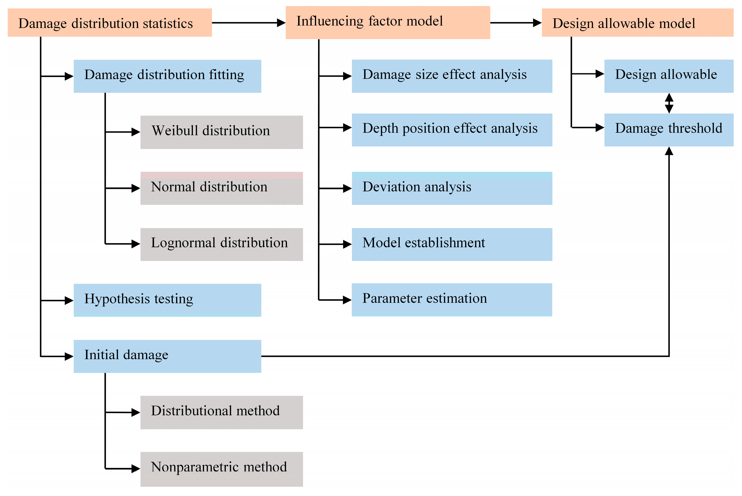
To clarify the proposed algorithm for compression design allowable determination, the implementation procedure is illustrated in Figure 9.
First, conduct the distribution fitting and goodness-of-fit testing on the delamination size and calculate the initial damage to cover most delaminations existing in the composite structures.
Secondly, examine the effect of damage size and depth position on the compression failure strain and construct the factor model of compression failure strain.
Finally, based on the assumed initial damage and the predicted compression failure strain, determine the compression design allowables for different composite aircraft structures.

5. Conclusions

This work presents a novel algorithm for compression design allowable determination of composites laminates with delaminations. First, a statistical investigation is conducted on the delamination size distribution of composite aircraft structures, where the deficiencies of the wing skins, wing ribs, horizontal tail skins, and horizontal tail ribs caused by manufacturing defects are considered. To approximate the most dangerous delamination that may emerge in the structures, the percentiles with upper confidence are estimated, defined as the initial damages. The statistical analysis demonstrates that the delamination samples of the considered structures are all in excellent agreement with the lognormal distribution.
Then a series of static compression tests are carried out on the composite laminates containing delaminations of different sizes and different depth positions. A factor model of compression failure strain is constructed to quantify the effects of delamination size and depth position. To estimate the model parameters, extended Kalman filter combined with variability analysis is employed. From the factor model, it can be seen that the delamination size has a significant influence on the compression failure strain.
To obtain the compression design allowable, the B-basis value of the factor model is estimated by using the one-sided tolerance factor. With the design allowable surface, the compression design allowable can be determined based on the damage distributions of composite structures, and the damage thresholds can be estimated when the design allowables are defined so as to provide references for the composite structures maintenance.
While it should be noted that this paper only counts the delamination data during manufacturing and considers the single delamination, thus the most dangerous damage sizes given are conservative due to the neglect of the delamination growth and the multiple delaminations in service. Therefore, the allowable strain should be adjusted when the data of delamination onset and propagation in service is available, so as to fully ensure the structural integrity.

Author Contributions

Conceptualization, J.G. and Y.Z.; methodology, Y.Z.; software, J.G.; validation, J.G., Y.Z. and K.C.; formal analysis, J.G.; investigation, J.G.; resources, Y.Z.; data curation, J.G. and K.C.; writing—original draft preparation, J.G.; writing—review and editing, Y.Z. and K.C.; visualization, J.G., Y.Z. and K.C.; supervision, Y.Z. and K.C.; project administration, Y.Z.; funding acquisition, Y.Z. All authors have read and agreed to the published version of the manuscript.

Funding

This research was funded by National Key Research and Development Program of China, grant number 2018YFF0216004.

Institutional Review Board Statement

Not applicable.

Informed Consent Statement

Not applicable.

Data Availability Statement

Not applicable.

Conflicts of Interest

The authors declare no conflict of interest.

Appendix A

Suppose the system model can be denoted as
x k = x k 1 + w k 1
y k = h k ( x k ) + v k
where x k is the state vector, y k is the measurement vector, h ( ) is a nonlinear function, and w k , v k are the perturbation sources with covariance of Q k and R k , respectively.
Linearize the measurement vector around x k = x ^ k by Taylor expansion with the high-order terms neglected:
y k = h k ( x ^ k ) + h k x | x ^ k ( x k x ^ k ) + v k = h k ( x ^ k ) + H k ( x k x ^ k ) + v k = H k x k + [ h k ( x ^ k ) H k x ^ k ] + v k = H k x k + z k + v k
where the x ^ k represents the estimation of x k before y k . z k and H k are defined as
z k = h k ( x ^ k ) H k x ^ k
H k = h k x | x ^ k
Moreover, the last filtered state estimate is as
x ^ k = E ( x k | y 1 , y 2 , , y k - 1 ) = E ( x k 1 | y 1 , y 2 , , y k - 1 ) = x ^ k 1 +
Then the error covariance matrix of x ^ k and x ^ k 1 + are
P k = E [ ( x k x k ) ( x k x k ) T ]
P k 1 + = E [ ( x k 1 x k 1 + ) ( x k 1 x k 1 + ) T ]
Substituting Equations (A1) and (A6) into Equations (A7) and (A8), it can be obtained as
P k = P k 1 +
Assuming that x ^ k + is a linear combination of x ^ k and y k :
x ^ k + = x ^ k + K k ( y k H k x ^ k z k )
where K k is a gain matrix to be determined.
Besides, Equation (A10) can be rewritten as
x ^ k + = x ^ k + K k [ y k h k ( x ^ k ) ]
According to Equations (A3) and (A10), the mean estimation error is written as
E ( ε x , k ) = E ( x k x ^ k + ) = E [ x k x ^ k K k ( y k H k x ^ k z k ) ] = E [ ε x , k 1 K k ( H k x k + v k H k x ^ k ) ] = ( I K k H k ) ε x , k 1 K k E ( v k )
And the summary of estimation error is
J k = E ( ε x , k T ε x , k ) = E [ Tr ( ε x , k ε x , k T ) ] = Tr P k +
Using Equation (A12), the error covariance matrix is described as
P k + = E ( ε x , k ε x , k T ) = E { [ ( I K k H k ) ε x , k 1 K k v k ] [ ( I K k H k ) ε x , k 1 K k v k ] T } = ( I K k H k ) E ( ε x , k 1 ε x , k 1 T ) ( I K k H k ) T K k E ( v k ε x , k 1 T ) ( I K k H k ) T ( I K k H k ) E ( ε x , k 1 v k T ) K k T + K k E ( v k v k T ) K k T
Due to ε x , k 1 is independent with v k , then
E ( v k ε x , k 1 T ) = E ( v k ) E ( ε x , k 1 T ) = 0
The Equation (A14) can be rewritten as
P k + = ( I K k H k ) P k ( I K k H k ) T + K k R k K k T
In order to minimize J k , let the derivative of J k with respect to K k be zero:
J k K k = 2 ( I K k H k ) P k ( H k T ) + 2 K k R k = 0
Finally, the gain matrix is obtained as
K k = P k H k T ( H k P k H k T + R k ) 1

References

  1. Wencheng, L. Principles for determining material allowable and design allowable values of composite aircraft structures. Procedia Eng. 2011, 17, 279–285. [Google Scholar] [CrossRef] [Green Version]
  2. Spendley, P.R. Design Allowables for Composite Aerospace Structures; University of Surrey: Surrey, UK, 2012. [Google Scholar]
  3. Mangalgiri, P.D. Design Allowable Considerations for use of Laminated Composites in Aircraft Structures. J. Indian Inst. Sci. 2013, 93, 571–592. [Google Scholar]
  4. MIL-HDBK-17-1F, Composite Materials Handbook, Volume 1 Polymer Matrix Composites Guidelines for Characterisation of Structural Materials; Department of Defense: Washington, DC, USA, 2002.
  5. CHM-17, Composite Materials Handbook: Volume 1: Polymer Matrix Composites; SAE International: New York, NY, USA, 2012.
  6. Vallmajó, O.; Cózar, I.R.; Furtado, C.; Tavares, R.; Arteiro, A.; Turon, A.; Camanho, P.P. Virtual calculation of the B-value allowables of notched composite laminates. Compos. Struct. 2019, 212, 11–21. [Google Scholar] [CrossRef]
  7. Furtado, C.; Pereira, L.F.; Tavares, R.P.; Salgado, M.; Otero, F.; Catalanotti, G.; Arteiro, A.; Bessa, M.A.; Camanho, P.P. A methodology to generate design allowables of composite laminates using machine learning. Int. J. Solids Struct. 2021, 233, 111095. [Google Scholar] [CrossRef]
  8. Shah, P.D.; Melo, J.D.D.; Cimini, C.A.; Ridha, M. Evaluation of Notched Strength of Composite Laminates for Structural Design. J. Compos. Mater. 2010, 44, 2381–2392. [Google Scholar] [CrossRef]
  9. Cózar, I.R.; Turon, A.; González, E.V.; Vallmajó, O.; Sasikumar, A. A methodology to obtain material design allowables from high-fidelity compression after impact simulations on composite laminates. Compos. Part A Appl. Sci. Manuf. 2020, 139, 106069. [Google Scholar] [CrossRef]
  10. Abumeri, G.; Abdi, F.; Raju, K.; Housner, J.; Bohner, R.; McCloskey, A. Cost effective computational approach for generation of polymeric composite material allowables for reduced testing. In Advances in Composite Materials—Ecodesign and Analysis; InTech Open: London, UK, 2011; pp. 247–270. [Google Scholar] [CrossRef] [Green Version]
  11. Nam, K.; Park, K.J.; Shin, S.; Kim, S.J.; Choi, I.-H. Estimation of Composite Laminate Design Allowables Using the Statistical Characteristics of Lamina Level Test Data. Int. J. Aeronaut. Space Sci. 2015, 16, 360–369. [Google Scholar] [CrossRef] [Green Version]
  12. Abdi, F.; Clarkson, E.; Godines, C.; DorMohammadi, S. A-B Basis Allowable Test Reduction Approach and Composite Generic Basis Strength Values. In Proceedings of the 18th AIAA Non-Deterministic Approaches Conference, San Diego, CA, USA, 4–8 January 2016. [Google Scholar]
  13. Suemasu, H. On the instability of multiple annular delaminations of axisymmetric laminates with arbitrary boundary conditions subjected to transverse load. Compos. Struct. 2020, 251, 112678. [Google Scholar] [CrossRef]
  14. Baluch, A.H.; Falcó, O.; Jiménez, J.L.; Tijs, B.; Lopes, C.S. An efficient numerical approach to the prediction of laminate tolerance to Barely Visible Impact Damage. Compos. Struct. 2019, 225, 111017. [Google Scholar] [CrossRef] [Green Version]
  15. Köllner, A.; Nielsen, M.W.; Srisuriyachot, J.; Rhead, A.T.; Butler, R. Buckle-driven delamination models for laminate strength prediction and damage tolerant design. Thin-Walled Struct. 2021, 161, 107468. [Google Scholar] [CrossRef]
  16. Ipek, G.; Arman, Y.; Çelik, A. The effect of delamination size and location to buckling behavior of composite materials. Compos. Part B Eng. 2018, 155, 69–76. [Google Scholar] [CrossRef]
  17. Kharghani, N.; Soares, C.G. Analytical and experimental study of the ultimate strength of delaminated composite laminates under compressive loading. Compos. Struct. 2019, 228, 111355. [Google Scholar] [CrossRef]
  18. Aslan, Z.; Şahin, M. Buckling behavior and compressive failure of composite laminates containing multiple large delaminations. Compos. Struct. 2009, 89, 382–390. [Google Scholar] [CrossRef]
  19. Jin, F.; Xu, P.; Xia, F.; Liang, H.; Yao, S.; Xue, J. Buckling of composite laminates with multiple delaminations: Part I Theoretical and numerical analysis. Compos. Struct. 2020, 250, 112491. [Google Scholar] [CrossRef]
  20. Heo, J.-H.; Shin, H.; Nam, W.; Om, J.; Jeong, C. Approximation of modified Anderson–Darling test statistics for extreme value distributions with unknown shape parameter. J. Hydrol. 2013, 499, 41–49. [Google Scholar] [CrossRef]
  21. Fu, H.M. A method of two-dimensional one-sided torlerance factors. Acta Aeronaut. Et Astronaut. Sin. 1993, 14, 166–172. [Google Scholar]
  22. Li, H.; Yao, Y.; Guo, L.; Zhang, Q.; Wang, B. The effects of delamination deficiencies on compressive mechanical properties of reinforced composite skin structures. Compos. Part B Eng. 2018, 155, 138–147. [Google Scholar] [CrossRef]
  23. Zhao, L.; Liu, Y.; Hong, H.; Wang, K.; Zhao, J. Compressive failure analysis for low length-width ratio composite laminates with embedded delamination. Compos. Commun. 2018, 9, 17–21. [Google Scholar] [CrossRef] [Green Version]
  24. ASTM D7137/D7137M-17. Standard Test Method for Compressive Residual Strength Properties of Damaged Polymer Matrix Composite Plates; ASTM International: West Conshohocken, PA, USA, 2017. [Google Scholar]
  25. ASTM D6641/D6641M-16. Standard Test Method for Compressive Properties of Polymer Matrix Composite Materials Using a Combined Loading Compression (CLC) Test Fixture; ASTM International: West Conshohocken, PA, USA, 2016. [Google Scholar]
  26. Zhe, L.A.; Pl, B.; Ns, C. Effect of delamination on the flexural response of [+45/45/0]2s carbon fibre reinforced polymer laminates. Compos. Struct. 2019, 209, 93–102. [Google Scholar]
  27. Hunt, G.W.; Hu, B.; Butler, R.; Almond, D.P.; Wright, J.E. Nonlinear Modeling of Delaminated Struts. AIAA J. 2004, 42, 2364–2372. [Google Scholar] [CrossRef]
  28. Simon, D. Optimal State Estimation: Kalman, H∞, and Nonlinear Approaches; John Wiley & Sons: Hoboken, NJ, USA, 2006; pp. 298–305. [Google Scholar]
Figure 1. CDF of delamination sizes for (a) Wing skin, (b) Wing rib, (c) Horizontal tail skin, and (d) Horizontal tail rib.
Machines 09 00307 g001
Figure 2. Initial damages with confidence of 95% and reliability of 90%. (a) Comparison of initial damages of different aircraft structures; Delamination distribution and initial damage of (b) Wing skin, (c) Wing rib, (d) Horizontal tail skin, and (e) Horizontal tail rib.
Machines 09 00307 g002
Figure 3. Sketch top and side views of the delaminated composite laminate (lengths in mm).
Machines 09 00307 g003
Figure 4. Compression failure strain and design allowable of laminates with delamination in (a) h / 3 and (b) h / 2 .
Machines 09 00307 g004
Figure 5. Compression failure strain of laminates with delamination at different depth positions.
Machines 09 00307 g005
Figure 6. The linear model of standard deviation and delamination size.
Machines 09 00307 g006
Figure 7. The compression failure strain surface.
Machines 09 00307 g007
Figure 8. The compression design allowable surface.
Machines 09 00307 g008
Figure 9. Design allowable determination for composite structures flowchart.
Machines 09 00307 g009
Table 1. Estimated parameters of the selected distributions for different composite structures.
DistributionWing
Skin
Wing
Rib
Horizontal
Tail Skin
Horizontal
Tail Rib
Weibull α 21.3422.1317.5416.52
β 1.161.251.511.30
R 2 0.97 (accept)0.95 (reject)0.90 (reject)0.89 (reject)
Normal μ 20.1420.3515.6215.03
σ 20.1521.3712.3314.85
R 2 0.83 (reject)0.79 (reject)0.79 (reject)0.70 (reject)
Lognormal μ 2.622.732.572.46
σ 0.880.710.570.65
R 2 0.99 (accept)0.99 (accept)0.94 (accept)0.96 (accept)
Table 2. ZT7H/5429 composite laminates test matrix.
Composite materialsZT7H/5429
Stacking sequence[-45/0/45/90/0/0/-45/90/45/0]S
Dimensions (mm3)150 × 100 × 2.5
Delamination size (mm)0Φ25Φ38Φ50
Delamination
depth position
h / 3 5555
h / 2 555
Number of specimen5101010
Table 3. Estimation results and errors of parameters.
ParametersEstimationError
A −7393.11
m 1.170.67
B 79699.65
Table 4. The compression design allowables of different composite aircraft structures.
Composite StructureInitial DamageCompression Design
Allowable (με)
Size (mm)Depth Position
Wing skinΦ63 h / 4 3934
Wing ribΦ454350
Horizontal tail skinΦ354630
Horizontal tail ribΦ384541
Table 5. Comparison of the conventional method and novel method for design allowable determination.
DelaminationCompression Design
Allowable (με)
% Difference
Single-Point MethodNovel Method
No delamination772977870.76
Φ 25   mm ,   h / 3 4347509517.21
Φ 25   mm ,   h / 2 4351517518.95
Φ 38   mm ,   h / 3 442346795.81
Φ 38   mm ,   h / 2 49404770−3.46
Φ 50   mm ,   h / 3 3871437713.07
Φ 50   mm ,   h / 2 45704474−2.11
Publisher’s Note: MDPI stays neutral with regard to jurisdictional claims in published maps and institutional affiliations.