Abstract
This study investigates the statistic behavior and parameter estimation problems of a double-sided, LCC-compensated, wireless power transfer system. Based on the commonly used wireless charging circuit model, this study proposes a five-step parameter estimation method, which is applicable to automotive static wireless charging systems. The eight parameters in the circuit model of this study are the most important key components of the wireless charging system. The study also found that, under certain conditions, the statistic mode of wireless charging systems has a specific distribution. However, the current status of these eight components for wireless charging of electric vehicles will have complex parameter drift problems. These drift problems will deteriorate the performance of the vehicle power systems. This study probes these factors and proposes some related mathematical theories. The noted factors can be applied to the analysis of the wireless charging system and provide alternative solutions to explain the deteriorations from coil misalignments. Both simulations and experiments are given to show the evaluated issues of the proposed study.
1. Introduction
A wireless power transfer (WPT) system is a resonant circuit consisting of transmitting and receiving coils and a compensation circuit. The compensation circuit determines the system performance, so its topology and parameter design have become the most important part of WPT systems. Regarding the wireless power transfer, many approaches are referenced and studied, such as magnetic flux induction, two-coil loosely coupled transformer, microwaves, and lasers [,]. Herein, the two-coil loosely coupled transformer, which can transfer power wirelessly with high efficiency across large air gaps, is of note. Four basic topologies are often referenced. Depending on how the compensation capacitors are added to the transmitting and receiving coils, they are simply named as series–series (SS), series–parallel (SP), parallel–series (PS), and parallel–parallel (PP) topologies [,]. Compared with the conventional topologies, the double-sided LCC compensation network is shown in Figure 1. It works as a current source to both the input and output [,,,,], which is suitable for light and heavy load conditions. Even when no load is placed in the load side, this topology can maintain suitable power distributions. This feature is very suitable for dynamic WPT because misalignment will commonly appear during the dynamic charging. The compensation capacitor is determined by the self-inductance, so coil misalignment does not significantly affect the resonance. Moreover, the circuit can realize unity power factor at the input, so there is no reactive power in the system. Furthermore, the circuit can be designed to provide zero-voltage-switching (ZVS) for the input inverter and eliminate the reverse recovery loss in the rectifier, so the system efficiency can reach 96%. Also, two of the inductors can be designed as planar inductors, integrated with the main coils to save space [,]. As illustrated in Figure 1a, this topology consists of one inductor and two capacitors at both the primary and secondary sides. Note that in Figure 1a, the double-sided LCC compensation topology was applied in the WPT unit of this paper. Its applications are highly suitable for both dynamic and static WPT of electric vehicles [,]. Additionally, due to the coils, the system can be placed under the chassis. Such structure of WPT is also easy to integrate into autonomous vehicles [,]. Eight parameters in the LCC circuit model are applied in the wireless charging system. These factors affect the system performance such as power, efficiency, and safety []. Basically, temperature, DC bias, and stochastic process may affect the parameter drift significantly. In practice, these drift affections will deteriorate the output performance of the vehicle systems. Clearly, parameter drift problems in static WPT and misalignment issues in dynamic WPT reveal similar effects to unsteady output, which are both important issues that could be investigated.
Figure 1.
Double-sided LCC compensation topology. (a) Double-sided LCC resonant circuit. (b) Equivalent circuit.
From Figure 1a, the equivalent circuit can be obtained, as Figure 1b. The circuit in Figure 1b can be described by the following equations:
where
Note that stands for the mutual inductance and k is the coupling coefficient. The resonance can be obtained in many ways. The useful conditions are obtained when all the diagonal elements are real and no imaginary part is present. Thus, the following resonant conditions can be derived:
Clearly, the resonant frequency should be controlled under the condition of
Accordingly, in order to obtain all the diagonal elements being real, with no imaginary parts, the following assumption is imposed in the sequel:
Hypothesis 1.
Assume that.
2. Problem Formulations
In this study, we consider a stochastic model of the wireless power transfer as follows:
where is a one dimensional Brownian motion, and , , , , . , , , and are given parameters; and
, , , , , , , and are parameters that need to be estimated. For simplicity, we denote that hereafter.
From Formula (6), we have
This gives
For simplicity, denote
We obtain .
3. Steady Behavior of Primary Current I1(t)
In order to clarify the asymptotic behavior of , we propose the following definition at first:
Definition 1.
is said to have the invariant measureif, and only if, there exists the probability measure, such that
for any Borel setand each fixed. From Formula (5), we obtain
As a matter of fact, it is well known that is the Ornstein–Uhlenbeck process. Thus, we point out that Bhattacharya and Waymire’s study [] is a readable literature devoted to the proof.
Result 3.1.
has the following probability density function:
Result 3.2.
has the following invariant measure:
Proof.
By Result 3.1, if we take on both sides of Formula (7), we obtain the following:
This yields that
is the invariant measure of . This completes the proof. □
Accordingly, the random variable has the probability density function .
4. Synthesis Process
4.1. Probability Density Function
Let
Clearly, for any , we have
Since and , are dependent on and , respectively, the values and , are also dependent on and , respectively.
Result 4.1.
Under Hypothesis 1, for any, we obtain the following:
Proof.
It is trivial from the statement of this section above. This completes the proof. □
4.2. Homogeneous Markov Chain
In this section, we assume , , and . Therefore, by Result 3.1, we have the following:
Let for , and
where
Take a proposal density function by
for each and define
In terms of Result 3.2, we have
where is determined by . Now, define the time homogeneous Markov chains on by the following transition probability: for any Borel, set , ,
where the dirac measure is defined by
Result 4.2.
Under Hypothesis 1 and, , , has the invariant measurewith density function
Proof.
By the definition of , for satisfying
we see
which implies
On the other hand, for , satisfying
we see
which also implies
Combining the above arguments, we obtain
for any . Now, from definition 1 and (8), for any Borel, set , , we integrate the following with respect to ,
This establishes
Moreover, since
we have
By induction, we obtain
for any Borel set , and each fixed positive number . Hence, is the invariant measure of . This completes the proof. □
4.3. Estimation Algorithm
For sake of estimating , we refer to the assumptions of Result 3.1 and [] via Metropolis–Hastings algorithm as follows. Result 4.2 ensures the convergence of the following estimation algorithm.
Step 1: Given any initial state on .
Step 2: Generate a candidate state from a uniform distribution on and a acceptance value from a uniform distribution on .
Step 3: Calculate
where is determined by and is determined by .
Step 4: If , then we accept , otherwise, take
and go back to Step 2.
Step 5: Repeat the previous steps until we obtain a convergent chain.
5. Simulations and Experiments
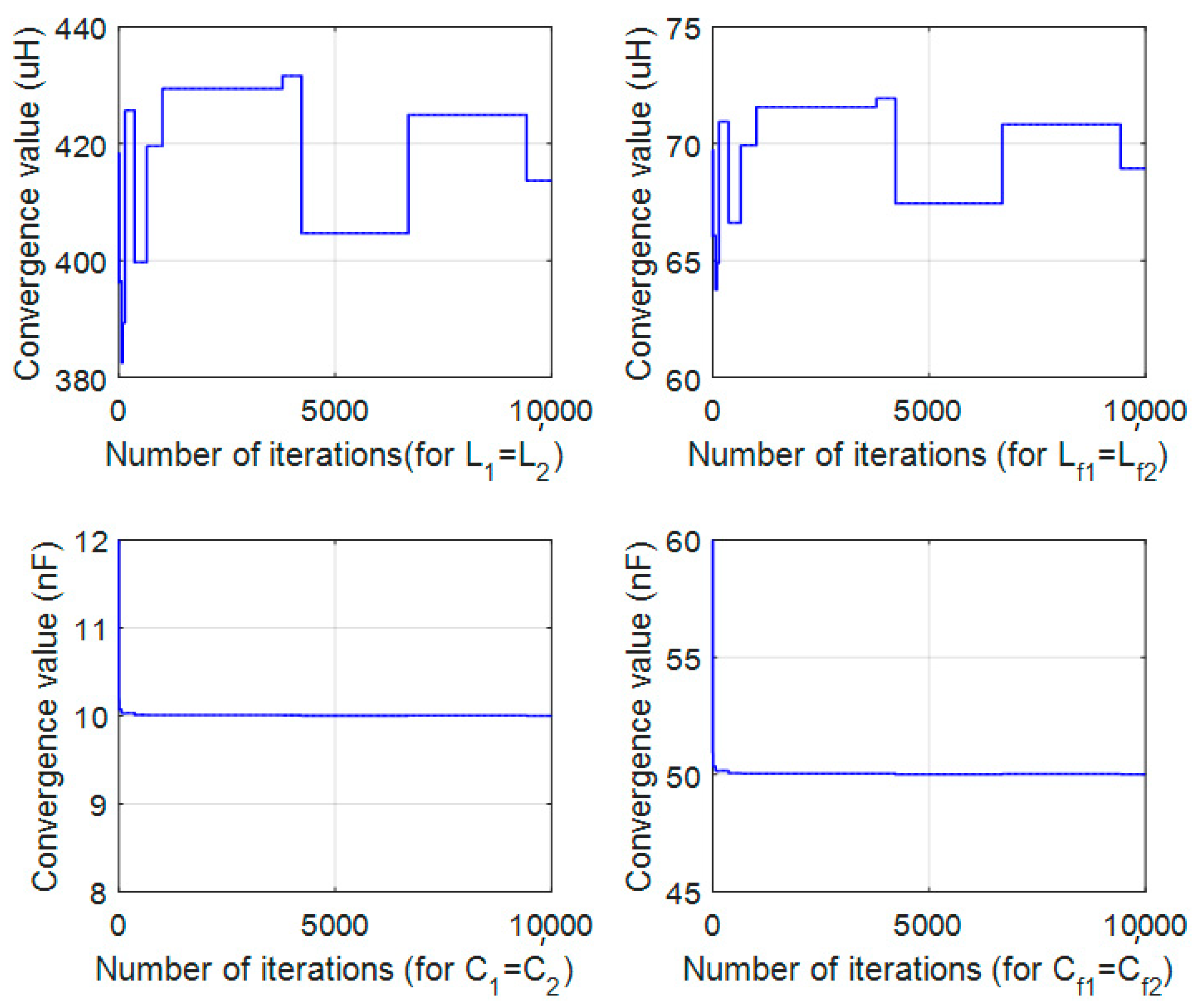
Under Hypothesis 1 and , , , for the sake of simplifying a simulation, we set , , and , , , , , and for each to guarantee that Hypothesis 1 holds. Additionally, we take and an initial state . Then, proceed the estimation algorithm as mentioned in Section 4.3. For from 1 to 10,000, the synthesized values were revealed in Figure 2. In Figure 2, all tests are done by 10,000 iterations. As can be seen in this figure, the sample path is reasonably well converged, which satisfies the conditions that an asymptotic stable circuit should have. Under the condition of Hypothesis 1, the convergent value of capacitance reaches its steady state quickly. However, the inductance has a slower convergent rate. The convergent speed of steady value is different between inductor and capacitor because of the dynamical behavior of LCC topology. Note that only static WPT fits this conclusion.
Figure 2.
Sample paths for .
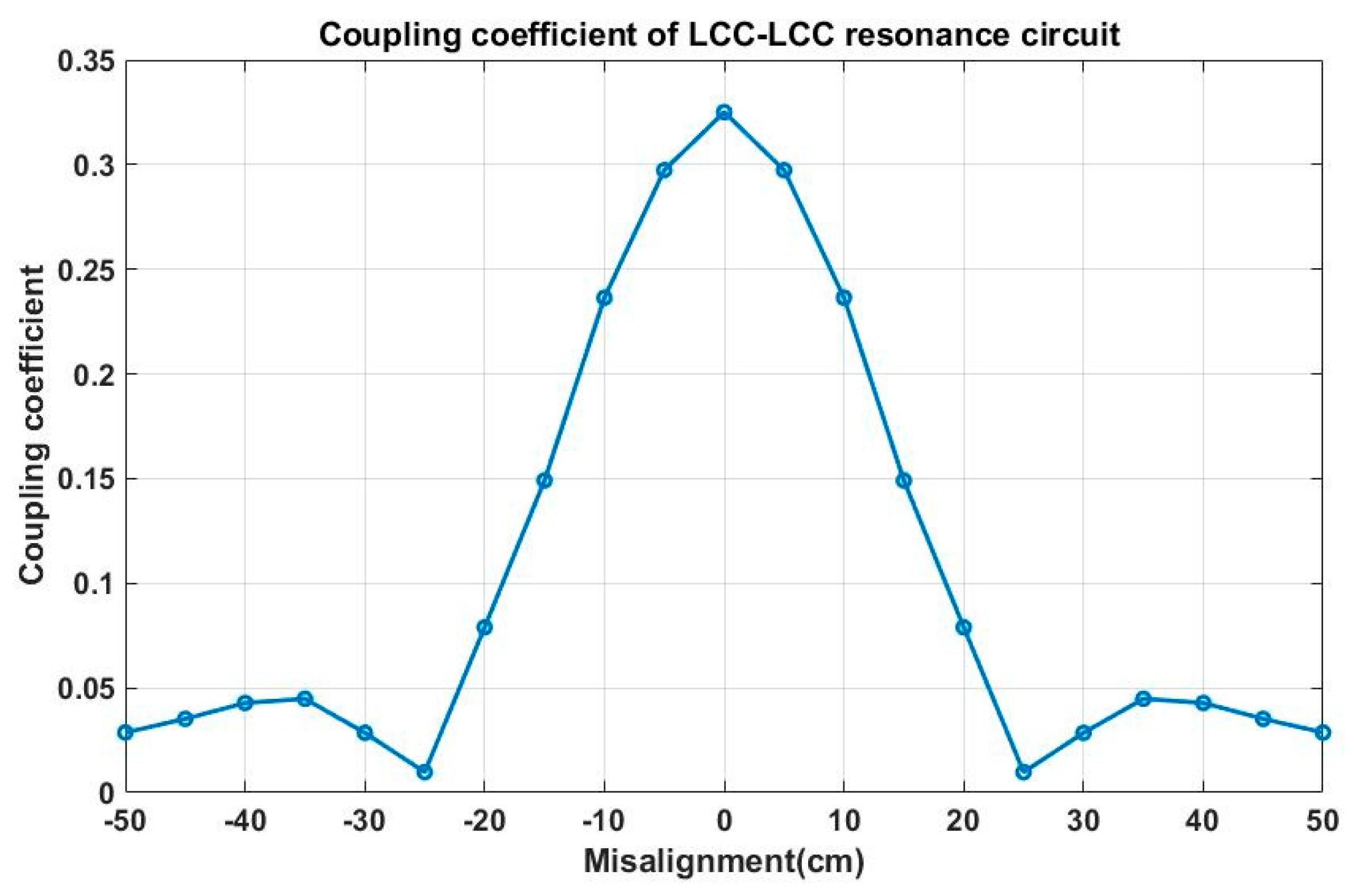
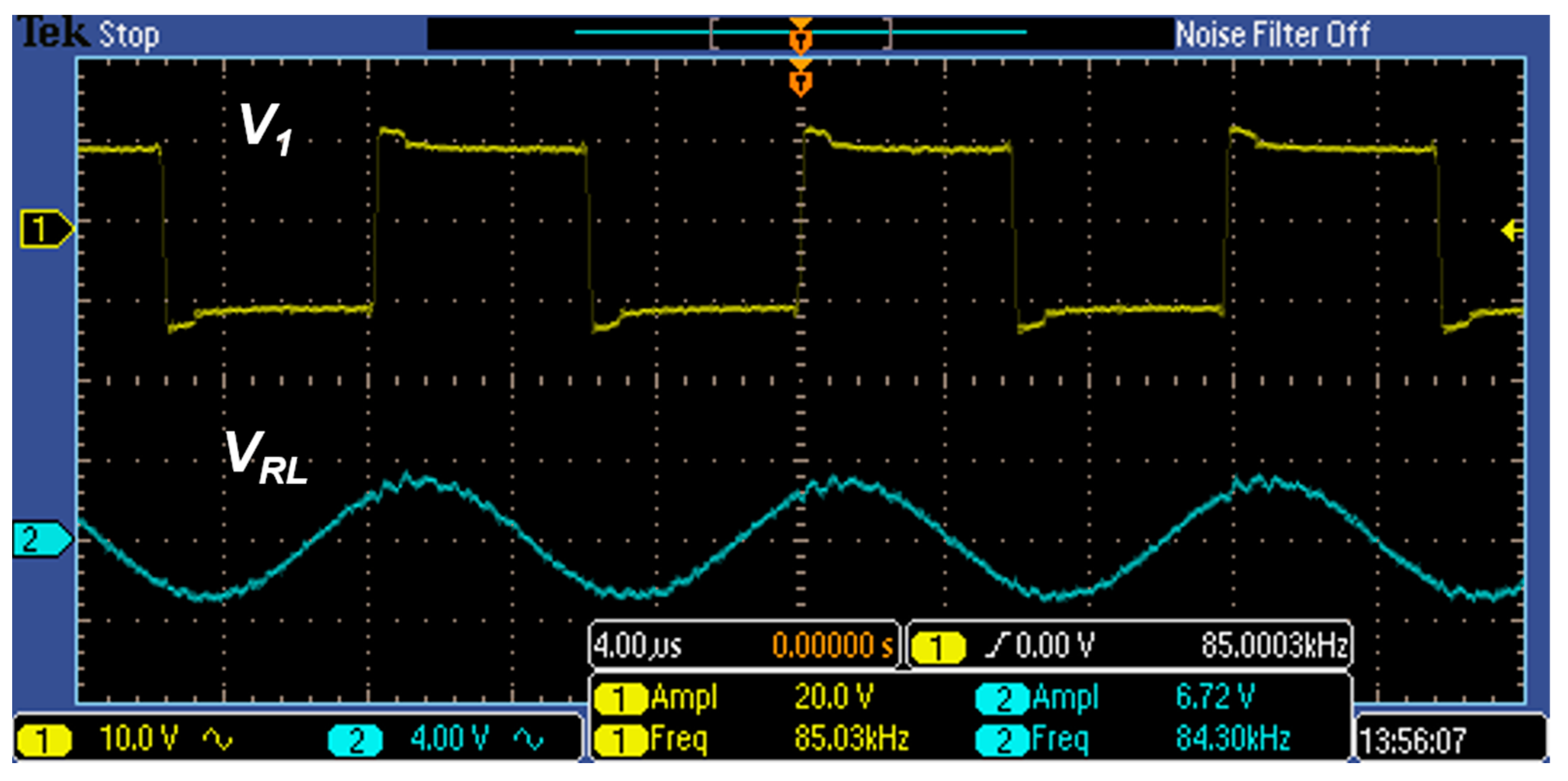
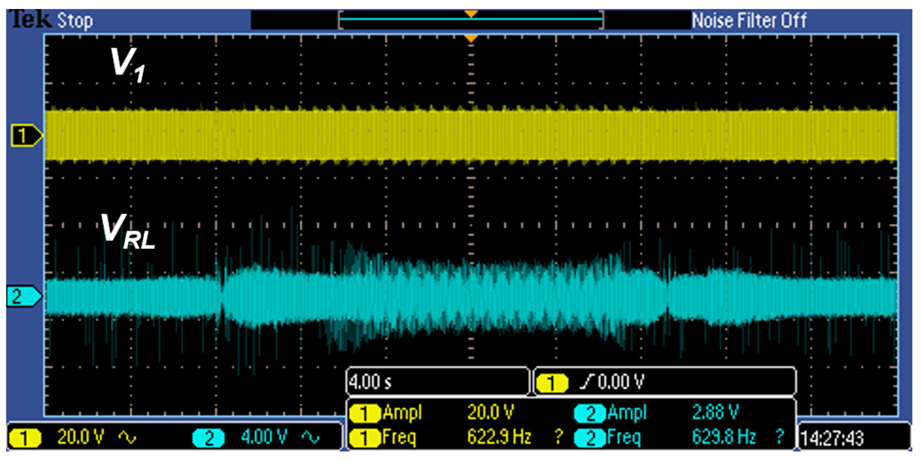
Misalignment in static WPT can be applied to simulate the approaching or leaving statuses (or both) of dynamic WPT. In dynamic WPT, parameter drift affects the transmission power and efficiency, respectively. Basically, the whole process of “approaching–central–leaving” of the dynamic WPT can be treated as a series of parameter varying, which can be modeled by stochastic process. Hence, using the stochastic model to probe the system performance is an appropriate solution. Via simulation, engineers can use the stochastic model to preview the system performance before the activation of dynamic WPT process. For further demonstrating the LCC-compensated performance in dynamic charging, a small scale of experiment was employed to show its feasibility. The verification experiments are carried out on the test bench, as shown in Figure 3. Table 1 illustrates the relevant specifications of test bench. Its rated DC voltage is 10V, which is a small scale of WPT for demonstration. Figure 4 is the measurement data for coupling coefficient. Figure 5 shows the resonant conditions. Clearly, the resonant frequency exactly falls on 85 kHz, which satisfies the requirement from WPT. To test the affections of misalignment, as shown in Figure 6, a scenario of dynamic movement of receiving coils are scheduled. The experimental result is revealed in Figure 7. Clearly, the received energy is sensitive to the misalignment, which is relevant to the coupling coefficient, as shown in Figure 4.
Figure 3.
Test bench of the experiment.
Table 1.
Specifications of the test bench.
Figure 4.
Measurement of coupling coefficient.
Figure 5.
Experimental result for WPT evaluation.
Figure 6.
Scenario of a dynamic movement.
Figure 7.
Misalignment result of the scheduled dynamic WPT.
6. Conclusions
Considering the misalignment in the WPT process, this study investigated the statistic model for double-sided, LCC-compensated, wireless power transfer system. The main contributions are considered as:
For the initial value , has the following probability density function:
In addition, has the following invariant measure:
Under Hypothesis 1, for any , we obtain
Additionally, if , , and , then the Markov chains with the state space have the following invariant measure:
for any Borel set .
The statistic mode of the wireless charging system constructed in this paper is suitable for dynamic wireless power transfer, based on the LCC topology. The stochastic model can be applied to simulate the deteriorations from misalignment of the static WPT. Therefore, it can be employed to evaluate the system’s features, such as efficiency in advance. After the simulation, engineers can apply the stochastic model to preview the power or the efficiency (or both) before the activation of the dynamic WPT process. This study analyzed eight key components on the circuit. When it is used for dynamic wireless charging scenarios, there will be complex parameter drift problems, which lead to the deterioration of the power systems. In consequence, from the perspective of statistic model, this paper discussed the performance deteriorations and put them into practice in WPT applications of electric vehicles. Additionally, for further evaluations, simulations and experiments were given to show the noted factors of the proposed study.
Author Contributions
Conceptualization, F.-R.H. and J.-S.H.; methodology, F.-R.H.; investigation, F.-R.H. and J.-S.H.; resources, F.-R.H. and J.-S.H.; data curation, F.-R.H.; writing—original draft preparation, F.-R.H. and J.-S.H.; writing—review and editing, F.-R.H. and J.-S.H.; funding acquisition, F.-R.H. and J.-S.H. All authors have read and agreed to the published version of the manuscript.
Funding
This work was financially supported by the Ministry of Science and Technology of Taiwan with Grands MOST 107-2115-M-142-001, MOST 110-2622-8-005-005-TE1, and MOST 108-2221-E-024-013-MY3.
Institutional Review Board Statement
Not applicable.
Informed Consent Statement
Not applicable.
Data Availability Statement
No new data were created or analyzed in this study. Data sharing is not applicable to this article.
Conflicts of Interest
The authors declare no conflict of interest. The funders had no role in the design of the study, in the collection, analyses, or interpretation of data, in the writing of the manuscript, or in the decision to publish the results.
References
- Li, S.; Li, W.; Deng, J.; Nguyen, T.D.; Mi, C.C. A Double-Sided LCC Compensation Network and Its Tuning Method for Wireless Power Transfer. IEEE Trans. Veh. Technol. 2015, 64, 2261–2273. [Google Scholar] [CrossRef]
- Hu, J.-S.; Lu, F.; Zhu, C.; Cheng, C.-Y.; Chen, S.-L.; Ren, T.-J.; Mi, C.C. Hybrid Energy Storage System of An Electric Scooter Based on Wireless Power Transfer. IEEE Trans. Ind. Inform. 2018, 18, 4169–4178. [Google Scholar] [CrossRef]
- Imura, T.; Hori, Y. Maximizing Air Gap and Efficiency of Magnetic Resonant Coupling for Wireless Power Transfer Using Equivalent Circuit and Neumann Formula. IEEE Trans. Ind. Electron. 2011, 58, 4746–4752. [Google Scholar] [CrossRef]
- Tsai, J.-S.; Hu, J.-S.; Chen, S.-L.; Huang, X. Directional Antenna Design for Wireless Power Transfer System in Electric Scooters. Adv. Mech. Eng. 2016, 8. [Google Scholar] [CrossRef] [Green Version]
- Bi, Z.; Kan, T.; Mi, C.C.; Zhang, Y.; Zhao, Z.; Keoleian, G.A. A Review of Wireless Power Transfer for Electric Vehicles: Prospects to Enhance Sustainable Mobility. Appl. Energy 2016, 179, 413–425. [Google Scholar] [CrossRef] [Green Version]
- Li, W.; Zhao, H.; Li, S.; Deng, J.; Kan, T.; Mi, C.C. Integrated LCC Compensation Topology for Wireless Charger in Electric and Plug-In Electric Vehicles. IEEE Trans. Ind. Electron. 2015, 62, 4215–4225. [Google Scholar] [CrossRef]
- Mosammam, B.M.; Mirsalim, M. New Integrated Tripolar Pad Using Double-Sided LCC Compensation for Wireless Power Transfer. IEEE Trans. Veh. Technol. 2020, 69, 15633–15643. [Google Scholar] [CrossRef]
- Yao, Y.; Wang, Y.; Liu, X.; Cheng, H.; Liu, M.; Xu, D. Analysis, Design, and Implementation of A Wireless Power and Data Transmission System Using Capacitive Coupling and Double-Sided LCC Compensation Topology. IEEE Trans. Ind. Appl. 2019, 55, 541–551. [Google Scholar] [CrossRef]
- Kan, T.; Lu, F.; Nguyen, T.; Mercier, P.P.; Mi, C.C. Integrated Coil Design for EV Wireless Charging Systems Using LCC Compensation Topology. IEEE Trans. Power Electron. 2018, 33, 9231–9241. [Google Scholar] [CrossRef]
- Zhang, X.; Kan, T.; You, C.; Mi, C.C. Modeling and analysis of AC Output Power Factor for Wireless Chargers in Electric Vehicles. IEEE Trans. Power Electron. 2017, 32, 1638–1650. [Google Scholar] [CrossRef]
- Hu, J.-S.; Wang, Y.; Fujimoto, H.; Hori, Y. Robust Yaw Stability Control for In-Wheel Motor Electric Vehicles. IEEE/ASME Trans. Mechatron. 2017, 22, 1360–1370. [Google Scholar] [CrossRef]
- Wang, K.; Wang, Y.; Wang, L.; Du, H.; Nam, K. Distributed Intersection Conflict Resolution for Multiple Vehicles Considering Longitudinal-Lateral Dynamics. IEEE Trans. Veh. Technol. 2021, 70, 4166–4177. [Google Scholar] [CrossRef]
- Yin, D.; Wang, J.; Du, J.; Chen, G.; Hu, J.-S. A New Torque Distribution Control for Four-Wheel Independent-Drive Electric Vehicles. Actuators 2021, 10, 122. [Google Scholar] [CrossRef]
- Guidi, G.; Lekkas, A.M.; Stranden, J.E.; Suul, J.A. Dynamic Wireless Charging of Autonomous Vehicles: Small-scale Demonstration of Inductive Power Transfer as An Enabling Technology for Self-Sufficient Energy Supply. IEEE Electrif. Mag. 2020, 8, 37–48. [Google Scholar] [CrossRef]
- Doan, V.; Fujimoto, H.; Koseki, T.; Yasuda, T.; Kishi, H.; Fujita, T. Allocation of Wireless Power Transfer System from Viewpoint of Optimal Control Problem for Autonomous Driving Electric Vehicles. IEEE Trans. Intell. Transp. Syst. 2018, 19, 3255–3270. [Google Scholar] [CrossRef]
- Song, K.; Yang, G.; Zhang, H.; Huang, X.; Jiang, J.; Lan, Y.; Huang, X.; Li, J.; Zhu, C. An Impedance Decoupling-Based Tuning Scheme for Wireless Power Transfer System under Dual-Side Capacitance Drift. IEEE Trans. Power Electron. 2021, 36, 7526–7536. [Google Scholar] [CrossRef]
- Bhattacharya, N.; Waymire, E.C. Stochastic Processes with Applications; John Wiley & Sons: New York, NY, USA, 1990. [Google Scholar]
- Chib, S.; Greenberg, E. Understanding the Metropolis-Hastings algorithm. Am. Stat. 1995, 49, 327–335. [Google Scholar]
Publisher’s Note: MDPI stays neutral with regard to jurisdictional claims in published maps and institutional affiliations. |
© 2021 by the authors. Licensee MDPI, Basel, Switzerland. This article is an open access article distributed under the terms and conditions of the Creative Commons Attribution (CC BY) license (https://creativecommons.org/licenses/by/4.0/).