Abstract
In order to better control the vibration of the rotor system so as to improve the stability and safety of the rotor, a novel vibration control solution is needed. In this paper, the multi-objective optimization problem is used for designing a novel integral squeeze film bearing damper (ISFBD). The method attempts to reduce the stiffness and stress convergence of ISFBD, which can greatly decrease the transmitted force of the rotor system and better use the damping effect to dissipate the vibration energy. The finite element model of ISFBD is established to analyze the stiffness and stress, and the correctness of the calculation is verified by setting up a stiffness test platform. The sensitivity of different structural parameters of stiffness and stress is analyzed by ANOVA. Meanwhile, the non-dominated sorting genetic algorithm (NSGA-II) and grey correlation analysis (GRA) algorithms are coupled for multi-objective optimization of stiffness and stress. The results indicate that optimized ISFBD can distribute 26.6% of the rotor system’s energy and reduce 59.3% of the transmitted force at the bearing location. It is also proved that the optimization strategy is effective, which can provide a useful method for ISFBD design in practical applications.
1. Introduction
With the development of modern science and technology, the rotor of a machine is developing towards higher speed and heavier loads. The problem of rotor vibration is becoming increasingly prominent, and finding an effective method to control the vibration of the machine is urgent. The excitation sources of the rotor mainly include internal and external excitation. Internal excitations contain imbalance, misalignment, friction and so on. External excitations are composed of fluid shock, thermal creep, etc. When the excitation frequency is close to the natural frequency, resonance occurs. This will not only shorten the life of the rotor, but also cause accidents and economic losses. Therefore, how to effectively control the vibration of the rotor is of great significance [1,2].
In consideration of rotor safety and a longer operation period, many scholars have proposed different vibration control methods. Xu et al. [3] developed a vibration monitoring system which can collect rotor vibration data in real time. However, the monitoring system only provided fault warnings. Rizvi et al. [4] designed a friction damper based on the principle of frictional energy dissipation to solve the problem of blade vibration. But the friction damper had a serious nonlinearity. Numanoy et al. [5] applied the radial active magnetic bearing system (AMBS) in the bearings of the overhung rotors to control the fault vibration. Nevertheless, various power electronic devices were still needed, and magnetic shielding directly affects signal feedback. In addition, Ma et al. [6] used metal rubber dampers to control vibration by braiding metal wires. The disadvantage of the shock absorber was that it only had an effect at the critical speed. He et al. [7] used the squirrel-cage squeeze film damper to reduce the vibration of the rotor, but this took up a lot of space and had serious nonlinearity, easily causing a nonlinear response. Bistable and locking phenomena may occur when the rotor passes a critical speed.
In terms of multi-objective optimization, Pourzangbar et al. [8] calculated the optimal performance of the combined brace-viscous damper system (BVDS) and pendulum tuned mass damper (PTMD) by particle swarm optimization (PSO) to slow down the dynamic response of the pipe frame platform. The results proved that the toggle configuration for the first to third layers and the chevron configuration of the top layer are the optimal layouts. Wang et al. [9] proposed a new evaluation method combining empirical model decomposition (EEMD) and entropy methods, which allowed a comprehensive evaluation of the tail pipe pressure pulsation phenomenon of a 200 MW Francis turbine. However, there was still a need to improve the method to make the characteristic results more accurate. Kuntoğlu et al. [10] discussed the optimization effect of the three components of the cutting force and the material removal rate of the harmonic artificial bee colony algorithm (H-ABC) in turning AISI 5140 steel to realize the optimal parameters in machining application. According to the results, H-ABC provides an effective solution compared with the commonly used method. Zhang et al. [11] applied a multi-dimensional optimization method based on a sequential quadratic programming (SQP) algorithm for the unbalanced force and unbalanced moment of multi-stage disks to solve the vibration problem of the tie rod rotor. This method can be used not only for the guidance of the tie rod rotor assembly, but also for vibration control in operation. Sun et al. [12] put forward a new multi-objective discrete robust optimization (MODRO) algorithm for the design of engineering structures involving uncertainties. The results showed that the algorithm can achieve optimal design in an effective way. Zhou et al. [13] used a genetic algorithm to optimize the stability of a rotor with a nonlinear seal. The main parameters of the optimization included seal radius, seal gap and seal length. Yet, the results demonstrated weak stability. Fotios et al. [14] conducted an experimental investigation using Taguchi L16 orthogonal array, selecting the best milling strategy and cutting conditions, as well as the appropriate tool to obtain the best process conditions so as to construct the impeller with the best dimensional accuracy and surface quality. The results showed that this optimization method improved the surface roughness of the impeller.
In view of the research status of the above-mentioned vibration control methods, the process of practical application is not only limited by the machine space, working environment and newly added additional devices, but there are also problems of nonlinearity and narrow control frequency range. Therefore, in response to these shortcomings, this paper designs a novel integral squeeze film bearing damper which has low stiffness and high damping. Consequently, the transmitted force of the rotor can be reduced and the energy dissipation can be enhanced at the same time. Moreover, it has a good vibration control effect on a wide frequency range. The structural design of ISFBD can change its structural performance, such as through stiffness and stress, which will lead to a change in the rotor system characteristics, thus affecting the safety and stability of the rotor system and providing a good vibration control strategy for industrial machines. In the meantime, there is a coupling relationship between the stiffness and stress performance of the ISFBD. When the stiffness decreases, the stress increases but weakens the strength of the ISFBD. When the stress decreases, the stiffness increases but impairs the vibration control effect of the ISFBD. Considering only one of the factors and ignoring the synergy between them tends to reduce the engineering applicability of ISFBD. Hence, the structural design of ISFBD is a complex optimization problem. In the design process, not only must the coupling relationship between stiffness and stress be considered, but also the influence on energy distribution, load limit and force transmission. It is not only necessary to ensure a good vibration control effect, but also to avoid structural fatigue failure of the rotor system. Consequently, how to balance the relationship between stiffness and stress is a key step in the design of ISFBD.
The structural optimization design of ISFBD provides good vibration control for the dynamic performance of the rotor system in terms of stability and safety. Nevertheless, there is a synergy between stiffness and stress which affects the engineering applicability. Therefore, it is of great significance to better balance the optimal design between these two structural parameters to improve the safety and stability of the rotor system. In this paper, the novel ISFBD is taken as the research object, and the structural parameters are selected as the design variables. The stiffness and stress of ISFBD with different structural parameters are modeled and calculated based on FEM and an experimental platform is built to verify the effectiveness of the model. On this basis, the weight of different structural parameters in stiffness and stress is analyzed by ANOVA, and the sensitivity of different structural parameters is obtained. The NSGA-II and GRA algorithms are coupled to perform the multi-objective optimization of the stiffness and stress, so as to realize the structural optimization design of ISFBD.
2. Dynamic Model and Weight Analysis Formula
2.1. Dynamic Model of ISFBD
The structure of ISFBD is mainly divided into outer flange, inner flange, elastomer and segmented squeeze film area. The elastomer mainly changes the stiffness of the structure, and the oil film mainly provides damping. When the inner and outer flange diameters, elastomer height and split zone spacing are kept at a constant value, the main structural parameters affecting the stiffness and stress of ISFBD include the axial length L, the distribution angle θ, the film gap δ and the radial height h, as shown in Figure 1. The vibration control mechanism of ISFBD mainly includes vibration isolation measures and damping energy dissipation. The structure can reduce the stiffness, which can effectively isolate the transfer of the excitation force generated by the rotor to the foundation and reduce the transmission force. Meanwhile, the oil film in ISFBD can dissipate the vibration energy through the squeezing effect.
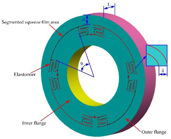
Figure 1.
Integral squeeze film bearing damper model.
The dynamic model of the ISFBD is shown in Figure 2. The outer and inner flange of the ISFBD is fixed to the bearing seat and the outer ring of the bearing, respectively. It is assumed that the stiffness and damping are isotropic, and the bearing and seat are rigid with respect to the damper. When the journal performs simple harmonic motion, the external force on the rotor system is .
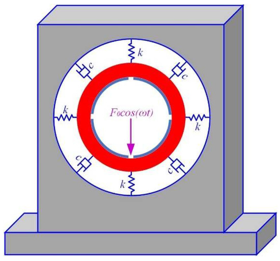
Figure 2.
Dynamic model of ISFBD.
The dynamic equation of the rotor system has the following expression [15,16,17,18]:
where m, c and k are the mass, damping and stiffness of the system, respectively.
When the system is excited by an external force at the beginning, it will have a transient response and a steady-state response. After a period of time, only the steady-state response remains. The steady-state solution is:
where
The force Ff(t) transmitted to the bearing and chamber through the ISFBD is:
Then the magnitude of this force is:
Through Equations (4) and (5), the force transfer coefficient can be obtained:
where , ξ is the ratio of damping.
The force transfer coefficient curve is displayed in Figure 3. The amplitude transferred to the foundation can be reduced by designing the low stiffness of the system, and the damping needs to be increased to drop the amplitude when passing the critical speed. When the system damping is constant, , Tf < 1 can effectively improve the vibration control effect. Therefore, it is very meaningful to reduce the stiffness of the ISFBD for rotor stability.
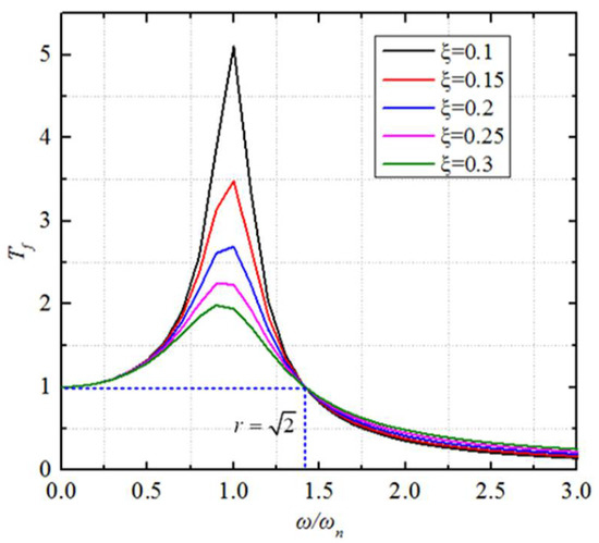
Figure 3.
Force transfer coefficient curve.
2.2. Weight Analysis Based on ANOVA
In this work, the ANOVA weight analysis method was used in order to investigate the weights of the different structural parameters of the ISFBD in terms of stiffness and stress respectively.
The total variance of ANOVA contains the intergroup variance and the error variance, where the total variance and its degree of freedom are [19,20]:
The variance and degree of freedom of intergroup are:
The variance and degree of freedom of error are:
The relationship between the three factors is as follows:
The mean square of total variation, intergroup variation and error variation can be conducted:
The F-value check equation is:
where F ≤ 1, indicating that the variation is mainly caused by errors and individual differences; that is, the experimental treatment is basically ineffective. If F > 1, there is a significant difference between the effects of experimental treatments.
Taking factor A as an example, the weight coefficients are:
The weight coefficients of other factors B, C, D and so on are similar to Equation (13) in this way.
3. Multi-Objective Optimization Based on NSGA-II and GRA Algorithm
It is difficult to ensure that the conflicting multi-objective optimization results can reach the minimum value as much as possible and at the same time. For this purpose, a multi-objective optimization with a combination of NSGA-II and GRA algorithms is used for designing ISFBD.
Assuming that there are r optimization objectives, the objective function can be expressed as [21,22,23]:
where
The NSGA-II algorithm is applied to introduce an elite retention strategy as well as a congestion comparison operator. The congestion of individuals in the population is cal-culated as Equation (16).
where id denotes the congestion of a given point i, fri+1 is the value of the i+1 fixed point in the objective function of r and fri−1 is the value of the i − 1 fixed point in the objective function of r.
The elite retention strategy, on the other hand, synthesizes the parent and child populations into a new population, arranging them in order of Pareto rank from lowest to highest and congestion from largest to smallest to obtain the Pareto frontier.
The application of the GRA algorithm is to select the optimized points in the Pareto frontier as a reference sequence for normalizing the orthogonal experimental data [24,25,26]:
where Xi*(k) and xi(k) are the sequence after the data processing and comparability sequence, respectively. k is the target value.
Determine the deviation ∆0i(k) between the values in Equation (18):
The deviation ∆0i(k) is the absolute difference between the baseline series x0*(k) and the comparable series xi*(k) after normalization.
Calculate the gray correlation coefficients:
where ∆max and ∆min are the global maximum and minimum values of normalized values, respectively. ρ is the distinguishing factor having values between 0 and 1. As stiffness and stress are equally important performance parameters for ISFBD, the equal weight age is given to stiffness and stress in the optimization process by giving the value of the distinguishing factor (ζ) as 0.5.
The multi-objective comprehensive gray relational grade (GRG) is:
Finally, the optimal solution of ISFBD in the orthogonal experiment is obtained, and the flow chart is shown in Figure 4.
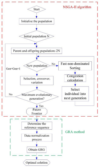
Figure 4.
Flow chart of multi-objective optimization of ISFBD.
4. Results and Discussion of Multi-Objective Optimization of ISFBD
4.1. Numerical Analysis of Baseline Initial Support
The rotor bearing is often connected to the bearing chamber, which is a rigid support in its initial state, and its static stiffness and stress distribution performance characteristics are analyzed by the static structural module of ANSYS FEM. The inner and outer diameters of the rigid support are 30 mm and 60 mm, respectively, and the thickness is 10 mm. Set the outer ring of the rigid support as a fixed constraint and apply a static force of 1000 N in the y direction to the inner ring. Figure 5 shows the static deformation cloud diagram and stress distribution cloud diagram of the rigid support. The stiffness calculated by K = F/δ is 1.14 × 10⁴ MN/m, and the corresponding maximum stress is 1.8496 MPa. While the relationship between bearing and rigid support is in series, and the stiffness of the bearing is about 100MN/m, which is much smaller than the rigid support, so the stiffness at the support is about equal to the stiffness of the bearing.
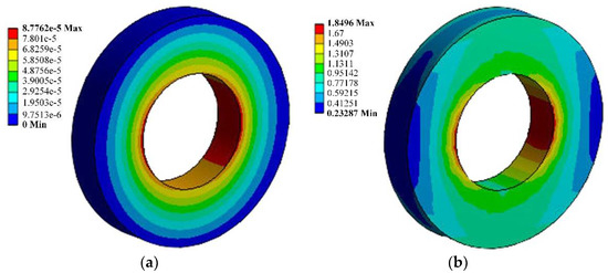
Figure 5.
Numerical results of rigid support: (a) Stiffness; (b) Stress.
In this paper, an example of a rotor system is established, as shown in Figure 6a. This model simulates the installation of ISFBD with different structural parameters by modifying the stiffness of the support, while ensuring parameters such as damping and unbalance remain unchanged, so as to strictly control the variables to more reasonably compare the influence of different structural parameters on the rotor system. The following three different working conditions were designed to investigate the influence of different support structures on the energy distribution and force transmission of the rotor system: (1) the rigid support is installed in the bearing chamber as a baseline; (2) ISFBD with lower stiffness under an ideal state; (3) ISFBD with multi-objective optimization. The energy distributions under both left and right supports with rigid support are 4.19% and 4.62%, respectively. The energy distribution at the shaft is 91.19%, as shown in Figure 6b. Most of the energy concentrated at the shaft will transfer the vibration outward along the bearing to the other components. If the ISFBD is attached at the bearing, the stiffness of the ISFBD is lower than that of the bearing, the stiffness at the support is about the stiffness of the ISFBD and the structure can reduce the transmission force of the rotor and control the vibration problem of the rotor effectively. As shown in Figure 6c, when the stiffness of ISFBD is 10 MN/m, the energy distribution at the left and right supports are 23.82% and 25.61%, which can reduce the transmitted force. It can be seen that the stiffness design of ISFBD is reasonable. Additionally, it does not exceed the tensile strength of the material when reducing the stiffness of ISFBD. The material is stainless steel with a yield strength of 515 MPa.
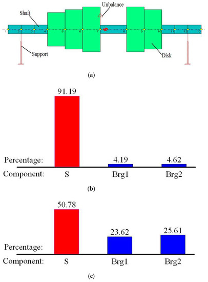
Figure 6.
Rotor system and energy distribution with different supports: (a) Rotor system with supports; (b) Rigid supports; (c) ISFBD supports.
4.2. Analysis and Validation of ISFBD
As shown in Figure 7, the four structural parameters of ISFBD including axial length L, radial height h, distribution angle θ and film gap δ are in different combinations for the analysis with the inner and outer flange diameters, as well as the elastomer height and length being constant. Similarly, ANSYS finite element analysis method is used to calculate the stiffness and stress of different structures of ISFBD. In the calculation, the outer ring of ISFBD is fixed, and the static force is applied in the y direction of the inner ring. The stiffness of different structures is calculated by K = F/δ.
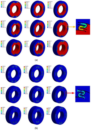
Figure 7.
Simulation results of Run No. 1–9 of stiffness and stress: (a) Stiffness plot; (b) Stress plot.
The boundaries of the parameters are determined as follows: (1) Axial length L: the inner diameter of ISFBD is 30 mm which corresponds to a bearing width of about 10 mm, considering that the width of the bearing chamber is 20 mm. For this purpose, axial lengths of 10 mm, 15 mm and 20 mm are set to investigate the influence on stiffness and stress. (2) Distribution angle θ: since the elastomers are symmetrically distributed at 90°, the oil film area should be longer than the elastomer area and the elastomer areas should also not be connected together. Otherwise, the unreasonable distribution angles obviously alter or destroy the structure, therefore 42°, 52° and 56° are chosen. (3) Film gap δ: if the film gap is set narrowly, the gap may be pressed close to 0 when subjected to a large load. This is detrimental to its function and rotor stability. If the film gap is set too large, the stiffness is too weak and may lead to fatigue fracture of the structure. To explore this issue, film gaps of 0.1 mm, 0.2 mm and 0.3 mm are set in a given space. (4) Radial height h: owing to the fact that the inner and outer diameters of the ISFBD have been determined, the elastomer moves up and down in that space, as close as possible to the outer and inner edges without damaging the structure. For this purpose, 2 mm, 4.8 mm and 7 mm were chosen as boundaries.
A four-factor, three-level orthogonal test table L9(34) is used to conduct three replicate experiments to increase sample diversity and reduce the effect of error. A total of 27 sets of data are shown in Table 1 and one series of results is presented in Figure 8. The ANOVA weight analysis method is used to determine the importance of structural parameters on performance characteristics. Moreover, the mean analysis of the main effects is performed using graphical plots, which is useful for understanding the trends of the input parameters on the response variables.

Table 1.
3 series of L9 orthogonal repeated experiments.
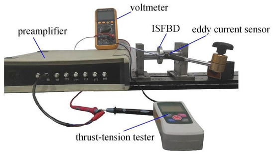
Figure 8.
Stiffness test rig.
In order to verify the correctness of model, the ISFBD of No. 2 in Table 1 is manufactured. Then a stiffness test platform is built, including a rigid test platform, two rigid chambers, a short shaft, a push-pull tester, an eddy current sensor, a preamplifier and a voltmeter, as shown in Figure 8. The parameters of each component are as follows:
1. Sensors: The range of the eddy current sensor and preamplifier is 0–1000 μm, sensitivity is 8 mV/μm, resolution is 1μm, operating frequency is 0–4000 Hz and linearity is 1.5%.
2. Preamplifier: The preamplifier is an electronic signal processor. The internal coil of the eddy current sensor provides high frequency alternating current. Changes of the sensor parameter due to changes of displacement can be detected.
3. Thrust-tension tester and voltmeter: The range of the thrust-tension tester is 2–500 N, with a division value of 0.1 N and an accuracy of ±0.5%. The voltmeter has a range of 0–20 V.
It is assumed that the structural characteristics are isotropic, so only the horizontal direction is analyzed. The thrust-tension tester is used to measure the force and the corresponding voltage value in the horizontal direction of the ISFBD and the shaft, respectively. According to the equation K = F/δ, the force-displacement diagram can be plotted. Further, its stiffness can be calculated as shown in Figure 9. The stiffness of ISFBD is 32.7 MN/m according to Figure 9. This is in good agreement with the calculated stiffness.
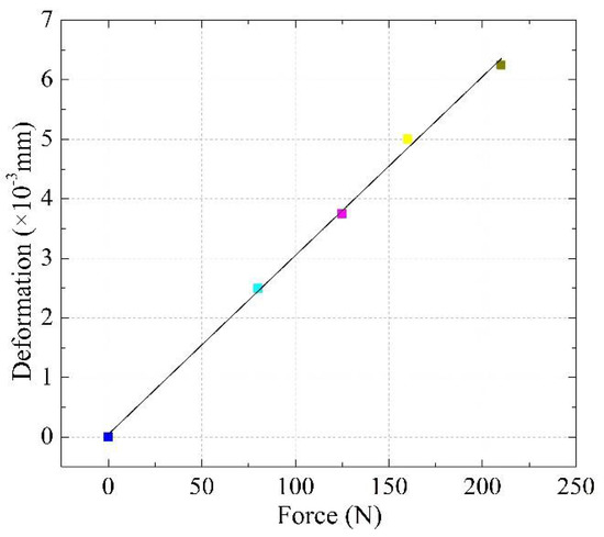
Figure 9.
Force-displacement diagram.
4.3. Weight Analysis of Stiffness and Stress
Combining Table 1 and Figure 10 shows that the stiffness increases as the axial length increases from 10 to 20 mm, with the maximum value of stiffness obtained at 20 mm. Similarly, the stiffness increases as the radial height increases and the film gap decreases. The distribution angle is found to have almost no significant effect on the stiffness.
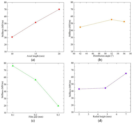
Figure 10.
Main effect for stiffness: (a) Axial length; (b) Distribution angle; (c) Film gap; (d) Radial height.
As can be seen from Table 2, the columns represent sources of variation, degrees of freedom (DF), sum of squares (SS), mean of squares (MS), F-value and p-value. The last column represents the percentage contribution of parameters. Axial length, radial height, film gap and distribution angle are important parameters for stiffness magnitude at 95% confidence level. The distribution angle has a smaller effect on the stiffness compared to the other parameters. The axial length and film gap are the most important parameters, with a percentage contribution of 27.94% and 58.72%. Figure 11 shows the percentage contribution of the structural parameters to the stiffness.
Table 2.
ANOVA for stiffness.
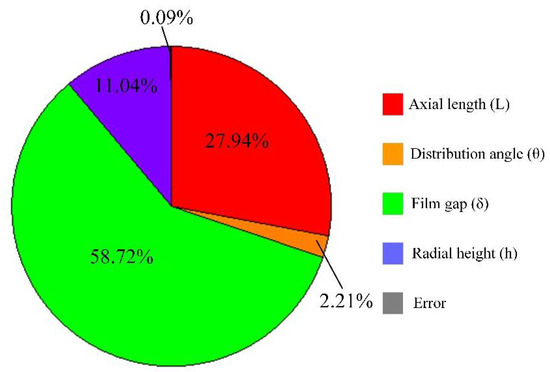
Figure 11.
Contribution of structural parameters on stiffness.
The effect of various structural parameters on the stress is presented in Figure 12. As the axial length increases, the stress decreases. Analogously, as the film gap increases, the stress gradually increases. As the radial height and distribution angle increase, the stress remains essentially constant.
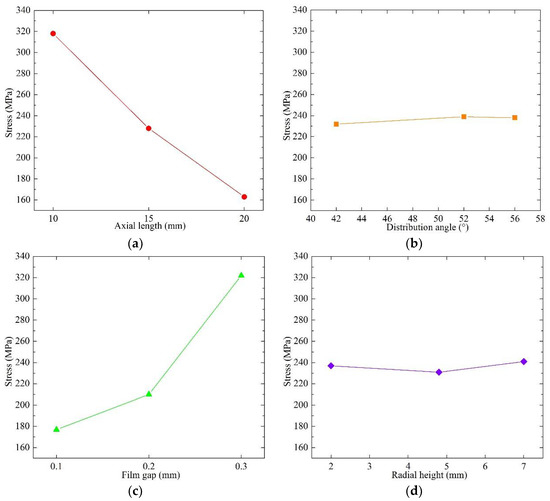
Figure 12.
Main effect for stress: (a) Axial length; (b) Distribution angle; (c) Film gap; (d) Radial height.
It can be concluded from Table 3 that the axial length and film gap are the most important factors, with contributions of 48.64% and 46.35%, respectively, for stress. Meanwhile, the distribution angle and radial height account for 0.12% and 0.21%, respectively, which are nearly negligible. Figure 13 shows the percentage contribution of structural parameters to the stress.
Table 3.
ANOVA for stress.
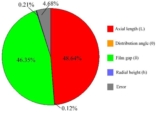
Figure 13.
Contribution of structural parameters on stress.
4.4. Multi-Optimization of ISFBD Using NSGA-II and GRA
The comprehensive expression of the low stiffness and low stress concentration optimization model is as follows:
The optimization is performed using NSGA-II. Due to the fact that the fitting equations do not have an extrapolation function, only the points with similar structural parameters in Table 1 can be selected to form the Patero optimal frontier, as shown in Figure 14.
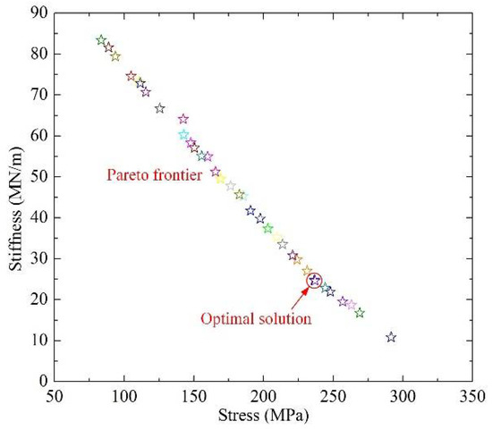
Figure 14.
Patero optimal frontier using NSGA-II.
For the rotor system in which ISFBD requires smaller stiffness and lower stress concentration, the optimal solution needs to be selected from the Pareto frontier. Considering that stiffness and stress play equally important roles, the optimal solution is marked in Figure 14, which corresponds to a stiffness and stress of K = 24.8 MN/m and σ = 219.1 MPa, respectively.
By using the above selected optimization points as the reference sequence, the three replicate experiments in Table 1 are averaged to generate individual responses for the two performance characteristics using the GRA algorithm. In the gray correlation model, the data are normalized to obtain the gray correlation corresponding to the two performances, and the comprehensive GRG is derived as shown in Table 4 and Figure 15.
Table 4.
Comprehensive GRG using GRA.
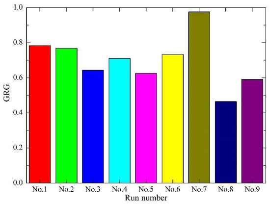
Figure 15.
Comprehensive GRG for different Run number.
From Table 4 and Figure 15, comparing the different structures of ISFBDs, it can be seen that the larger the comprehensive GRG is, the more optimized the structure is. No. 7 clearly has the comprehensive GRG of 0.9726 which can provide the best structural configuration, where the axial length is 20 mm, the distribution angle is 42°, the oil film gap is 0.3 mm and the radial height is 4.8 mm, resulting in a stiffness of 26.7 MN/m and a stress of 229 MPa for the ISFBD.
Substituting these parameters into the rotor system (Figure 6a) shows that the ISFBD can make the energy distribution at the two supports at 12.7% and 13.9%, and then dissipate the energy through its internal oil film damping, which can make the rotor system reduce the 59.3% external transmitted force (the damping coefficients under different kind of supports are the same) and improve the vibration control performance as shown in Figure 16a,b. Comparing Figure 6c with Figure 16a, Figure 6c shows the rotor energy distribution obtained with the more ideal ISFBD structural parameters characteristics, while Figure 16a shows the rotor energy distribution obtained with the actual optimized ISFBD structural parameters. Since the stiffness of Figure 16a is larger than that of Figure 6c, it can be concluded that as the stiffness decreases, it can effectively reduce the vibration energy on the shaft and improve the energy distribution at the bearing. It also reveals that the energy at the bearing can be better dissipated through the squeezing effect.
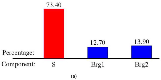
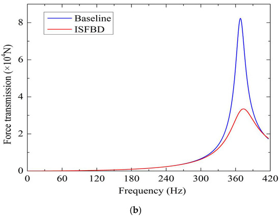
Figure 16.
Vibration control performance of the optimized ISFBD: (a) Energy distribution; (b) Force transmission.
The stress is much smaller than the compressive strength, so it can carry a larger external excitation force without suffering fatigue failure and has a wider application range.
5. Conclusions
In this paper, aimed at addressing the vibration problem of the rotor system, a multi-objective optimization method was proposed to design a novel integral squeeze film bearing damper to better match the corresponding rotor system, so as to control the vibration of the system. The stiffness and stress of ISFBD with different structural parameters were calculated, and a platform was built to verify the accuracy of the model. Then, the ANOVA method was used to analyze the weight of each parameter of ISFBD on stiffness and stress. Finally, the NSGA-II and GRA algorithms were coupled to optimize the design of ISFBD. The following are key takeaways of this research:
(1) The ISFBD is designed to verify the stiffness calculated by the FEM model. Experiment validation can prove the correctness of the model.
(2) The sensitivity of the input variable parameters to performance characteristics is analyzed using the ANOVA method. For the stiffness, axial length and film gap are the most important factors, with percentage contributions of 27.94% and 58.72%. For the stress, axial length and film gap dominated with 48.64% and 46.35% contributions, respectively. This helps to focus on which structural parameters should be major concerns in the design of ISFBD.
(3) In order to access low stiffness and less stress concentration, a combined NSGA-II and GRA algorithm is used. Compared with the initial support baseline, the optimal solution provides a stiffness of 26.7 MN/m, which makes the energy distribution accounted for 26.6% and reduces the force transmission rate by 59.3% at ISFBD. The stress also meets the strength condition.
On the one hand, the method obtained in this paper can play a guiding role in the design of the ISFBD. On the other hand, it can ensure safety and stability when the rotor is working. In the future, the influencing factors of damping will be studied. Also, the combination of jointly optimized stiffness, stress and damping will be taken into account.
Author Contributions
Conceptualization, Y.Z.; methodology, Y.Z.; software, Y.Z.; validation, Y.Z., J.Y. and G.Z.; formal analysis, Y.Z.; investigation, Y.Z. and W.Y.; resources, L.H.; data curation, Y.Z.; writing—original draft preparation, Y.Z.; writing—review and editing, L.H. and X.J.; visualization, Y.Z.; supervision, L.H.; project administration, L.H.; funding acquisition, L.H. and X.J. All authors have read and agreed to the published version of the manuscript.
Funding
This research was funded by the National Science and Technology Major Project of China (Grant No. 2017-IV-0010-0047), China Postdoctoral Science Foundation Funded Project (Grant No. 2020M670113) and the Fundamental Research Funds for the Central Universities (Grant No. JD2003).
Institutional Review Board Statement
Not applicable.
Informed Consent Statement
Not applicable.
Data Availability Statement
Not applicable.
Acknowledgments
The authors would like to thank the coauthors for their help and suggestions. The authors are also very grateful to the editors and the reviewers for their careful reading and helpful comments.
Conflicts of Interest
The authors declare no conflict of interest.
References
- Bai, H.; Liu, X.; Li, H.; Zhang, W.; Meng, G.; Li, M.; Wang, X. Nonlinear dynamic characteristics of a large-scale tilting pad journal-bearing rotor system. J. Vibroeng. 2014, 16, 4045–4064. [Google Scholar]
- Zhou, W.; Qiu, N.; Wang, L.; Gao, B.; Liu, D. Dynamic analysis of planar multi-stage centrifugal pump rotor system based on a novel coupled model. J. Sound Vib. 2018, 434, 237–260. [Google Scholar] [CrossRef]
- Xu, X.; Lei, Y.; Li, Z. An incorrect data detection method for big data cleaning of machinery condition monitoring. IEEE Trans. Ind. Electron. 2020, 67, 2326–2336. [Google Scholar] [CrossRef]
- Rizvi, A.; Smith, C.W.; Rajasekaran, R.; Evans, K.E. Dynamics of dry friction damping in gas turbines: Literature survey. J. Vibrat. Control 2016, 22, 296–305. [Google Scholar] [CrossRef]
- Numanoy, N.; Srisertpol, J. Vibration reduction of an overhung rotor supported by an active magnetic bearing using a decoupling control system. Machines 2019, 7, 73. [Google Scholar] [CrossRef] [Green Version]
- Ma, Y.; Liang, Z.; Wang, H.; Zhang, D.; Hong, J. Theoretical and experimental steady-state rotordynamics of an adaptive air film damper with metal rubber. J. Sound Vib. 2013, 332, 5710–5726. [Google Scholar]
- He, B.; Ouyang, H.; He, S. Dynamic response of a simplified turbine blade model with under-platform dry friction dampers considering normal load variation. Appl. Sci. 2017, 7, 228. [Google Scholar] [CrossRef] [Green Version]
- Pourzangbar, A.; Vaezi, M. Optimal design of brace-viscous damper and pendulum tuned mass damper using Particle Swarm Optimization. Appl. Ocean Res. 2021, 112, 102706. [Google Scholar] [CrossRef]
- Wang, W.; Chen, Q.; Yan, D.; Geng, D. A novel comprehensive evaluation method of the draft tube pressure pulsation of Francis turbine based on EEMD and information entropy. Mech. Syst. Signal Process. 2019, 116, 772–786. [Google Scholar] [CrossRef]
- Kuntoğlu, M.; Acar, O.; Gupta, M.; Sağlam, H.; Sarikaya, M.; Giasin, K.; Pimenov, D. Parametric optimization for cutting forces and material removal rate in the turning of AISI 5140. Machines 2021, 9, 90. [Google Scholar] [CrossRef]
- Zhang, Y.; He, L.; Yang, J.; Wang, J.; Zhu, G. Vibration control of tie rod rotors with optimization of unbalanced force and unbalanced moment. IEEE Access 2020, 8, 66578–66587. [Google Scholar] [CrossRef]
- Sun, G.; Zhang, H.; Fang, J.; Li, G.; Li, Q. A new multi-objective discrete robust optimization algorithm for engineering design. Appl. Math. Model. 2018, 53, 602–621. [Google Scholar] [CrossRef]
- Zhou, W.; Wei, X.; Zhai, L. Nonlinear characteristics and stability optimization of rotor-seal-bearing system. J. Vibroeng. 2014, 16, 818–831. [Google Scholar]
- Stratogiannis, F.; Galanis, N.; Karkalos, N.; Markopoulos, A. Optimization of the manufacturing strategy, machining conditions, and finishing of a radial impeller. Machines 2019, 8, 1. [Google Scholar] [CrossRef] [Green Version]
- Lu, K.; He, L.; Zhang, Y. Experimental study on vibration reduction characteristics of gear shafts based on ISFD installation position. Shock Vib. 2017, 2017, 7246356. [Google Scholar] [CrossRef] [Green Version]
- Zhang, Y.; He, L.; Yang, J.; Wan, F.; Gao, J. Vibration control of an unbalanced single-side cantilevered rotor system with a novel integral squeeze film bearing damper. Appl. Sci. 2019, 9, 4371. [Google Scholar] [CrossRef] [Green Version]
- Kamesh, D.; Pandiyan, R.; Ghosal, A. Passive vibration isolation of reaction wheel disturbances using a low frequency flexible space platform. J. Sound Vib. 2012, 331, 1310–1330. [Google Scholar] [CrossRef]
- Brungart, T.; Riggs, E. Rotor isolation for vibration and noise reduction. J. Vib. Acoust. 2003, 125, 407–411. [Google Scholar] [CrossRef]
- Burr, T.; Martin, K.; Norman, C.; Zhao, K. Analysis of variance for item differences in verification data with unknown groups. Sci. Technol. Nucl. Ins. 2019, 9, 1769149. [Google Scholar] [CrossRef]
- Kyratsis, P.; Markopoulos, P.; Efkolidis, N.; Maliagkas, V.; Kakoulis, K. Prediction of thrust force and cutting torque in drilling based on the response surface methodology. Machines 2018, 6, 24. [Google Scholar] [CrossRef] [Green Version]
- Bakhshinezhad, S.; Mohebbi, M. Multi-objective optimal design of semi-active fluid viscous dampers for nonlinear structures using NSGA-II. Structures 2020, 24, 678–689. [Google Scholar] [CrossRef]
- Jiang, R.; Jin, Z.; Liu, D.; Wang, D. Multi-objective lightweight optimization of parameterized suspension components based on NSGA-II algorithm coupling with surrogate model. Machines 2021, 9, 107. [Google Scholar] [CrossRef]
- Torabi, S.; Alibabaei, S.; Bonab, B.; Sadeghi, M.; Faraji, G. Design and optimization of turbine blade preform forging using RSM and NSGA-II. J. Intell. Manuf. 2017, 28, 1409–1419. [Google Scholar] [CrossRef]
- Zhi, X.; Zhu, X.; Liu, Y.; Gu, Z. The method of gray model control for the vibration of rotor system. Kybernetes 2004, 33, 464–469. [Google Scholar]
- Lei, Y.; Zhou, D.; Zhang, H. Investigation on performance of a compression-ignition engine with pressure-wave supercharger. Energy 2010, 35, 85–93. [Google Scholar] [CrossRef]
- Shinde, A.; Pawar, P. Multi-objective optimization of surface textured journal bearing by Taguchi based grey relational analysis. Tribol. Int. 2017, 114, 349–357. [Google Scholar] [CrossRef]
Publisher’s Note: MDPI stays neutral with regard to jurisdictional claims in published maps and institutional affiliations. |
© 2021 by the authors. Licensee MDPI, Basel, Switzerland. This article is an open access article distributed under the terms and conditions of the Creative Commons Attribution (CC BY) license (https://creativecommons.org/licenses/by/4.0/).