Article

Cooling Performance Analysis of Outside Fins of the Closed Circuit Axial Piston Transmission

1
Institute of Process Equipment, College of Energy Engineering, Zhejiang University, Hangzhou 310027, China
2
State Key Laboratory of Fluid Power and Mechatronic Systems, Zhejiang University, Hangzhou 310027, China
*
Author to whom correspondence should be addressed.
Machines 2021, 9(1), 17; https://doi.org/10.3390/machines9010017
Submission received: 15 December 2020 / Revised: 7 January 2021 / Accepted: 12 January 2021 / Published: 16 January 2021
(This article belongs to the Section Machines Testing and Maintenance)

Abstract

:
Realizing conversion between fluid power and mechanical energy, the closed circuit axial piston transmission (CCAPT) plays a vital and indispensable role in miscellaneous industries. The frictional loss and leakage loss inside the system give rise to the inevitable temperature rise. In order to prolong the life of the device, a cooling structure on the outside of the CCAPT is designed for promoting heat dissipation. Based on the relevant heat transfer law and the temperature distribution of internal machinery elements, a spiral fin structure is designed at the shell side. With the help of numerical simulation, the effects of fin height, fin pitch, and fin thickness on the thermal performance are studied. The flow field and temperature field on the outside of the fin structure are obtained as a guidance for enhancing heat dissipation effect. Results indicate that the area of rotating elements tend to accumulate heat, where more attention should be paid for a better cooling effect. In addition to this, a moderate increase of fin height, fin pitch and fin thickness has a positive effect on heat transfer enhancement. The peak value of Nusselt number is obtained with a fin height of 7.5 mm, which is about 2.09 times that of the condition without the fin structure. An increase in fin pitch improves both heat transfer performance and comprehensive performance at the same. When fin pitch is 30 mm, Nusselt numberincreases 104% over the original condition.

1. Introduction

Energy shortages have attracted wide attention worldwide, in terms of energy supply, energy storage, energy consumption, and so on [1,2]. The compact structure, smooth transmission, and high efficiency make the closed circuit axial piston transmission (CCAPT) a significant part for the development of the engineering machinery, which contains a variable displacement axial piston pump and a fixed displacement axial piston motor, realizing the conversion between fluid power and mechanical energy. The oil from the pump flows in the motor directly, while the hydraulic transmission and the mechanical transmission take place at the same time. The intense heat production and inevitable temperature rise pose a great threat to the life of the device. As is known, over temperature will bring about adverse impact on the elements, the hydraulic fluid, and the working properties of the hydraulic system [3]. For the sake of protecting hydraulic components, great significance is attached to various heat dissipating arrangement or other cooling methods [4]. Simultaneously, the cooling efficiency, waste heat and operation cost should be taken into consideration. Optimization design of the oil supplement system is an effective solution [5], which is not discussed in this paper.
Data show that cooling equipment consumes about 30–50% of the power consumption [6]. In need of additional apparatus, liquid cooling is usually expensive and complex [7,8]. When it comes to heat transfer augmentation of the air-side, fin configuration is considered as one of the effective methods. The easy fabrication and various types make fins a choice for heat transfer augmentation on the shell side, and the heat transfer coefficient on the air side could be 50–150% larger than that without fins. The selection of fin type varies with the controlling temperature and the application occasion, including rectangular fin [9], spiral fin [10], louvered fin [11], slit fin [12], wavy fin [13], perforated fin [14], etc. The fin type is dependent on the use of heat exchange structure, which makes a difference to the heat transfer efficiency. Lee et al. [15] analyzed the air-side thermal characteristics in a spiral fin-and-tube heat exchanger. The j-factor was measured with various fin pitches and numbers of tube rows for the inline and the staggered fin alignment. Kim [16] focused on the wet surface heat transfer and compared performance between louver fin and slit fin. For higher efficiency, the slit fins are arranged radial to the tube to make the flow direction and the slit direction identical. Pongsoi et al. [17] carried out experiments to prove that fin pitch had a negligible impact on air-side heat transfer coefficient in the L-footed spiral fin-and-tube heat exchanger.
There are some similarities between the CCAPT and the axial piston pump. The study of the axial piston pump could shed light on the performance of the CCAPT. Three crucial friction pairs consist of a slipper-swash plate pair, piston-cylinder pair, and valve plate-cylinder pair. With respect to lubrication and sealing, they are tightly related with the volumetric efficiency, mechanical efficiency, temperature rise, operational reliability, and working life. Norgard [18] proposed a simple experimental method to measure the power loss transported away to the oil in a hydrostatic pump. Such a method could also be applied to other hydraulic components. Olems [19] analyzed the temperature distribution of a swash plate type axial piston pump by means of simulation model and experimental measurement. From the perspective of theoretical analysis, Iboshi et al. investigated the fluid film lubrication of the slipper bearing, which also played a significant role in the swash plate-type axial piston pump. A theoretical analysis was given [20] and certified by experimental values later [21]. Furthermore, in a gesture to diminish power loss, a design method for the slipper was introduced [22] with the guidance of former study, taking oil-film parameters and slipper size into consideration. Xu et al. [23] investigated the effect of drain pressure on the height of the lubricating oil film. Apart from the sliding bearing, the lubricating gap can also function as a sealing element. Wieczorek [24] utilized the simulation tool CASPAR to calculate the non-isothermal gap flow in the bearing and sealing gaps of a swash plate-type axial piston pump, together with the fluid force and loss resulted from viscous friction and leakage flow.
Despite individual friction pair, some researchers focused on the thermodynamic performance of the whole water hydraulic pump. Li et al. [25] established an integrated thermal model of a water lubricating axial piston pump including heat generation and heat dissipation. The accuracy of simulation was verified by the measurement results of temperature sensor and thermal imager. With the capability of presenting the kinematics, dynamics and flowing characteristics, the model developed by Xu et al. [26,27,28] could investigate the axial piston pump explicitly and in detail. The hydro-mechanical loss can be derived from the accurate interaction force between contact parts, despite the complexity of the structure, the lubrication condition, and the motion of parts. Furthermore, the distribution proportion of hydro-mechanical loss generated in different friction pairs can be obtained under various working conditions. Results showed that piston cylinder pair and slipper swash plate pair are the main sources of hydro-mechanical loss at full displacement conditions and the proportion changes with the decrease of displacement. Under a wide range of operating ranges, the change tendencies of compression flow loss and leakage flow loss with the decreasing pump displacement are investigated by Xu et al. [29].
The application of fin structure to the shell is an attempt to improve its heat transfer characteristics, and prolong its service life. The size and weight of CCAPT has great limitation on the arrangement of fin structure. In a gesture to determine the distribution range of the heat dissipation structure, the internal temperature distribution of the CCAPT is investigated with the knowledge of heat transfer path. With the aim of decreasing the maximum temperature of shell, the effects of fin height h, fin pitch p and fin thickness t on the thermal performance are studied by the means of numerical simulation, considering that the finite volume method is a useful tool [30,31]. The flow field and temperature field on the outside of the fin structure are also obtained as a guidance for improving the heat dissipation effect. This work is beneficial for further research on the cooling process of the CCAPT.

2. Analysis and Modeling

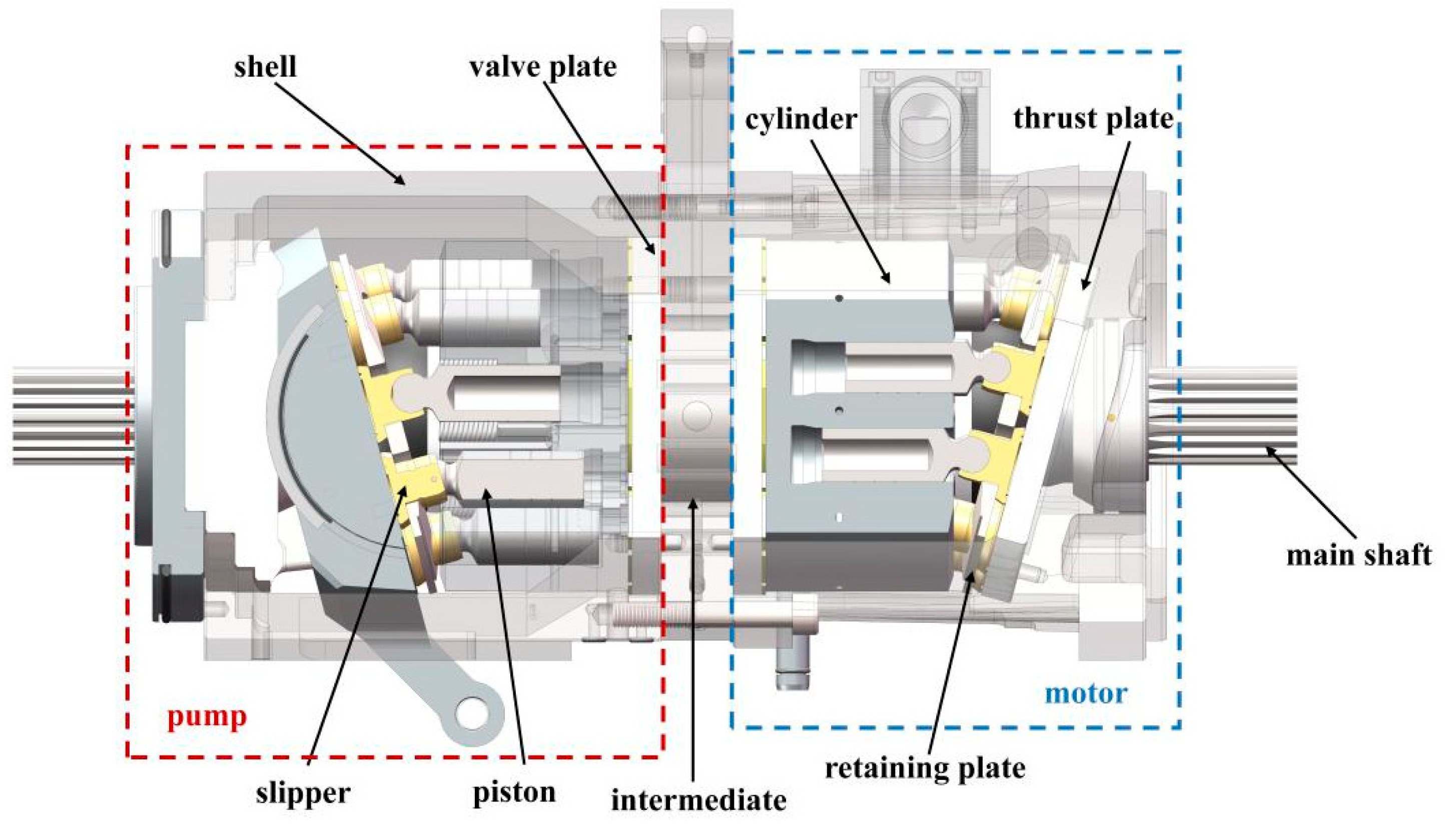
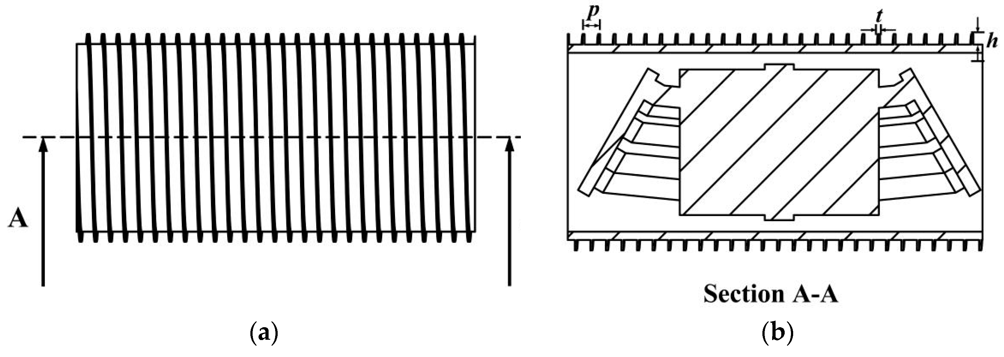
2.1. Geometrical Model
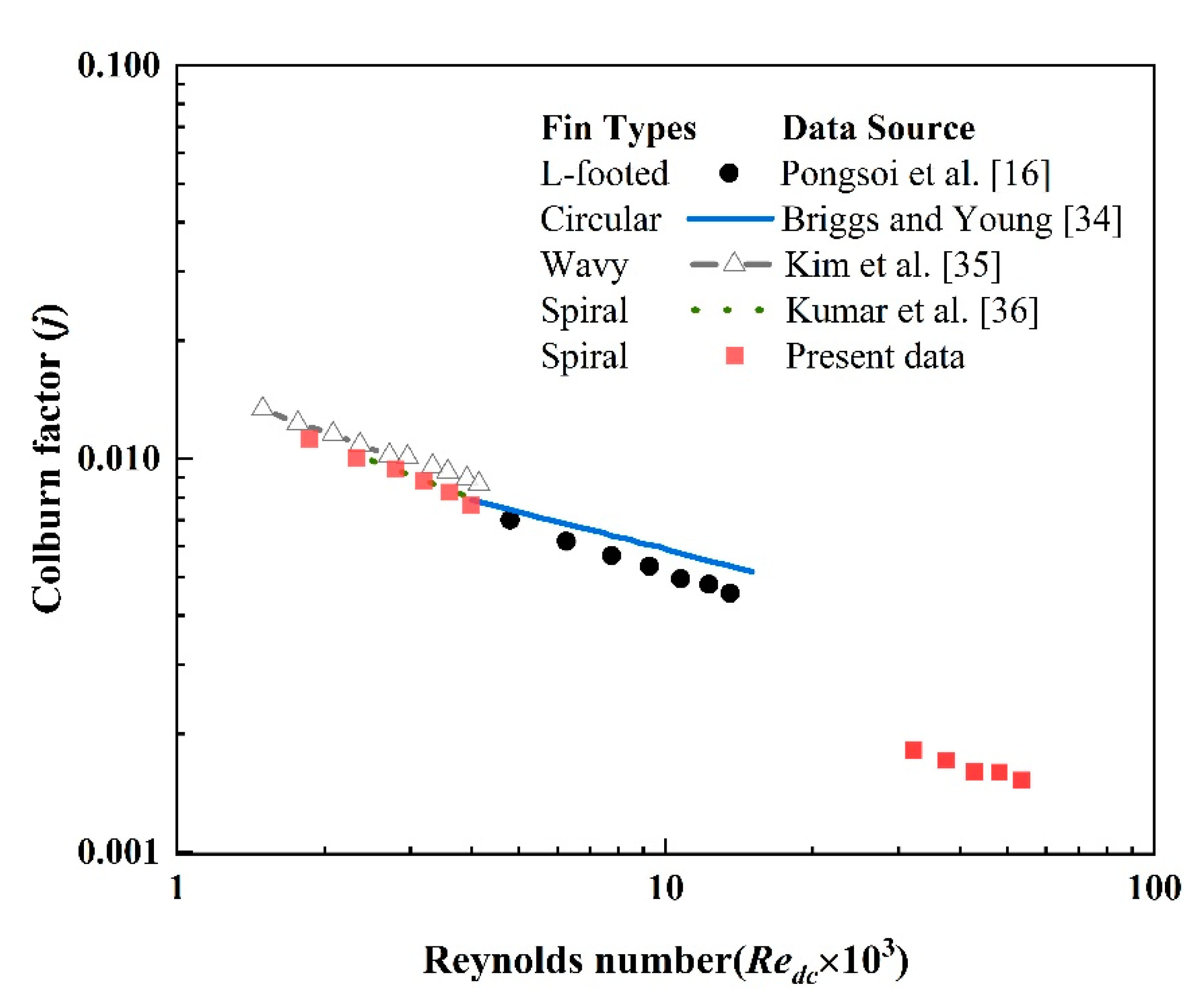
Figure 1 displays the schematic view of the CCAPT, which is mainly consisted of an axial piston pump and an axial piston motor. Serving as the power source, axial piston pump occupies an important position in the hydraulic system. The volumes in the cylinder and the piston cavity vary with the reciprocating motion of piston pushed by the swash plate, during which axial piston pump realizes the conversion from mechanical power to liquid pressure energy. The fixed displacement motor is driven by the variable displacement pump. Taking the overall dimension into consideration, the arrangement of fin structure is subjected to certain restrictions. In this investigation, a spiral fin structure is designed at the shell side on the basis of relevant heat transfer law and temperature distribution of the CCAPT. An optimization design of geometrical parameters is given to refrain from deformation caused by uneven heating. With the help of computational fluid dynamics, manpower and material resources could be saved and a comprehensive evaluation could be presented [32].
As depicted in Figure 2, the investigated geometrical parameters include the height, pitch and thickness of the fin structure. The height ranges from 5 mm to 15 mm while the thickness from 2 mm to 4 mm. The pitch increases from 10 mm to 30 mm, with an interval of 5 mm. After simplification, the internal machinery elements can be seen in Figure 2b.
The physical properties of materials for shell of CCAPT are presented in Table 1. As illustrated, the material of pump housing is 40Cr while that for motor housing is ZL105.

2.2. Data Reduction

Figure 3 demonstrates the heat transfer path, including the heat transferred between the shell and fluid, as well as shell and surroundings. Both convective and radiative heat transfer play a part in the heat dissipation. The rotating part exchanges heat with fluid through the way of convection and transfers heat to the shell by the means of conduction. According to the first law of thermodynamics, the temperatures of the shell and fluid could be calculated by the achievement of energy balance under the steady state.
The rotation of cylinder agitates the oil inside the shell, resulting in the forced convective heat transfer between the shell and internal fluids, which can be written as:
Q c f = α c f ( T cn T f ) A c f
where Q c f represents the convective heat transfer rate between the shell and fluids; αcf represents the convection coefficient between the shell and fluids; Tcn and Tf represent the temperature of inner surface and fluids, respectively; Acf represents the heat transfer area between the shell and fluids.
α c f = λ f d c f N u
where λf is the coefficient of thermal conductivity; dcf is the characteristic diameter of the inner surface; Nu is the Nusselt number.
In the turbulent flow, the forced Nusselt number can be expressed as:
N u = 0.027 Re 0.8 Pr 0.33
where Re is the Reynolds number; Pr is the Prandtl number.
The heat transfer between the shell and the ambient environment tends to be natural convective heat transfer. It can be described as:
Q c h 1 = α c h ( T cw T h ) A c h
where Q c h 1 represents the convective heat transfer rate between the shell and surroundings; αch represents the convection coefficient between the shell and surroundings; Tcw and Th represent the temperature of the outer surface and the environment, respectively; Ach represents the heat transfer area between the shell and the environment.
Nusselt number of natural convection can be derived as:
N u = 0.6 + 0.387 { Re · Pr G r · Pr [ 1 + ( 0.559 / Pr ) ] 9 / 16 } 0.33
where Gr is the Grashof number.
The radiative heat transfer rate between the shell and ambient environment can be calculated as:
Q c h 2 = ε σ ( T cn 4 T h 4 ) A c h
where ε is the blackness of shell material and σ is the Stefan–Boltzmann constant.
The heat transfer rate of forced convection between the rotating element and fluids inside the system can be expressed as:
Q s f = α s f ( T s T f ) A s f
where αsf represents the convective heat transfer coefficient between rotating elements and fluids; Ts represents the surface temperature of rotating elements; Asf represents the heat transfer area between rotating elements and fluids.
The heat transfer rate of thermal conduction between rotating elements and the pump shell can be written as follows:
Q c s = λ c ( T s T cw ) h c A c s
where λc is the thermal conductivity; hc is the thickness of the pump shell; Acs is the contact area between rotating area and the shell.
The heat transfer coefficient can be calculated as follows:
h i = Q η 0 A a Δ T L M T D
where Q refers to heat transfer quantity; Aa refers to the total heat transfer area; ΔTLMTD refers to the logarithm mean temperature difference; and η0 refers to the surface coefficient of the fin, which can be obtained from Equation (10):
η 0 = 1 A f A a ( 1 η f )
where Af is the area of the fin structure; ηf is the fin efficiency, which is determined in the following equation:
η f = tanh ( n l ) n l
where l is half the length of the fin height and parameter n is given by:
η f = 2 h k f t
where kf is the thermal conductivity of the material of the fin structure.
The heat transfer characteristic can be evaluated by the Colburn factor j, a non-dimensional physical parameter expressed as follows:
j = h ρ u c p Pr 2 / 3
where ρ, u, and cp represent the density, the velocity and the specific heat capacity of the fluid, respectively.

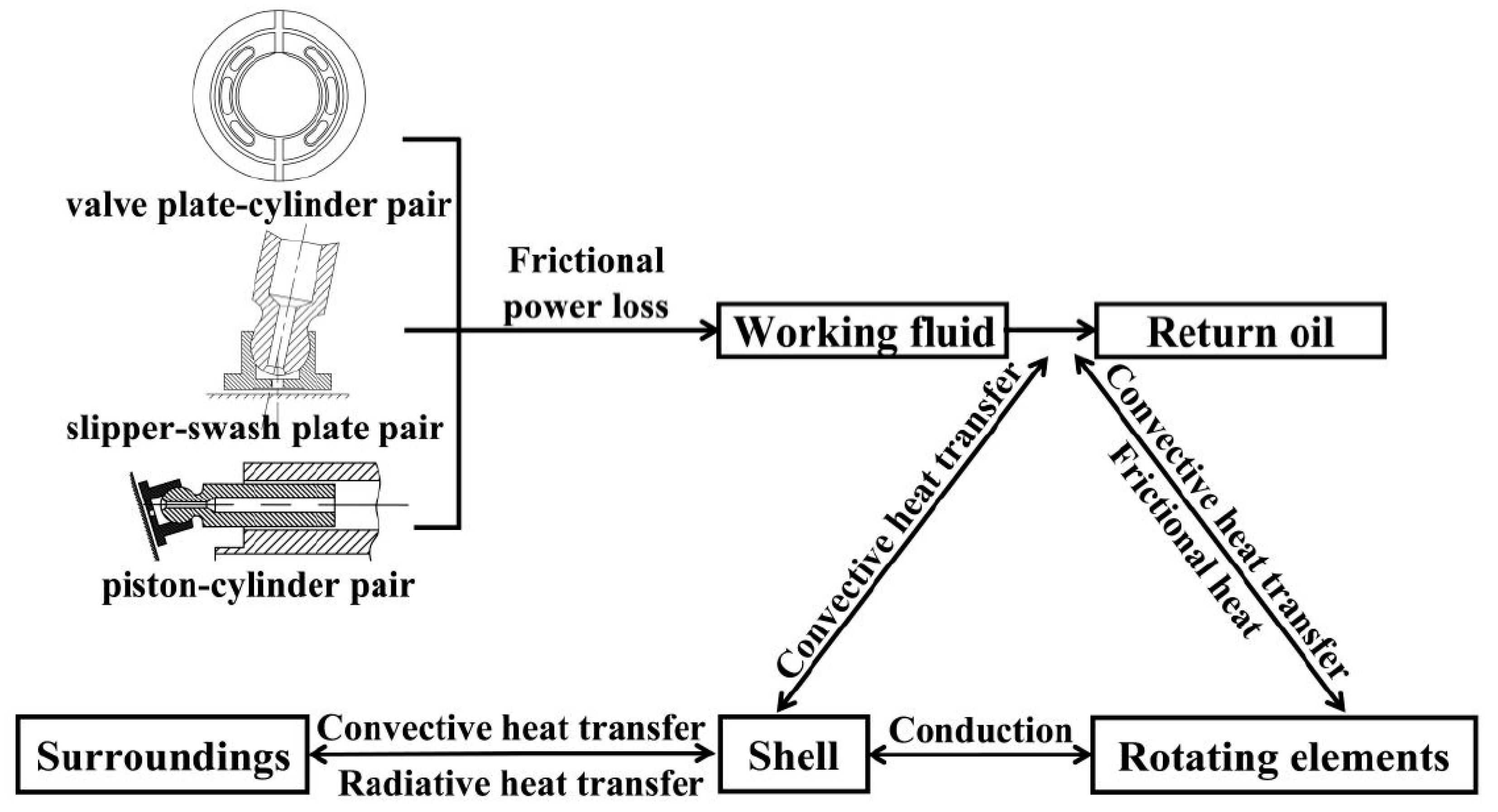
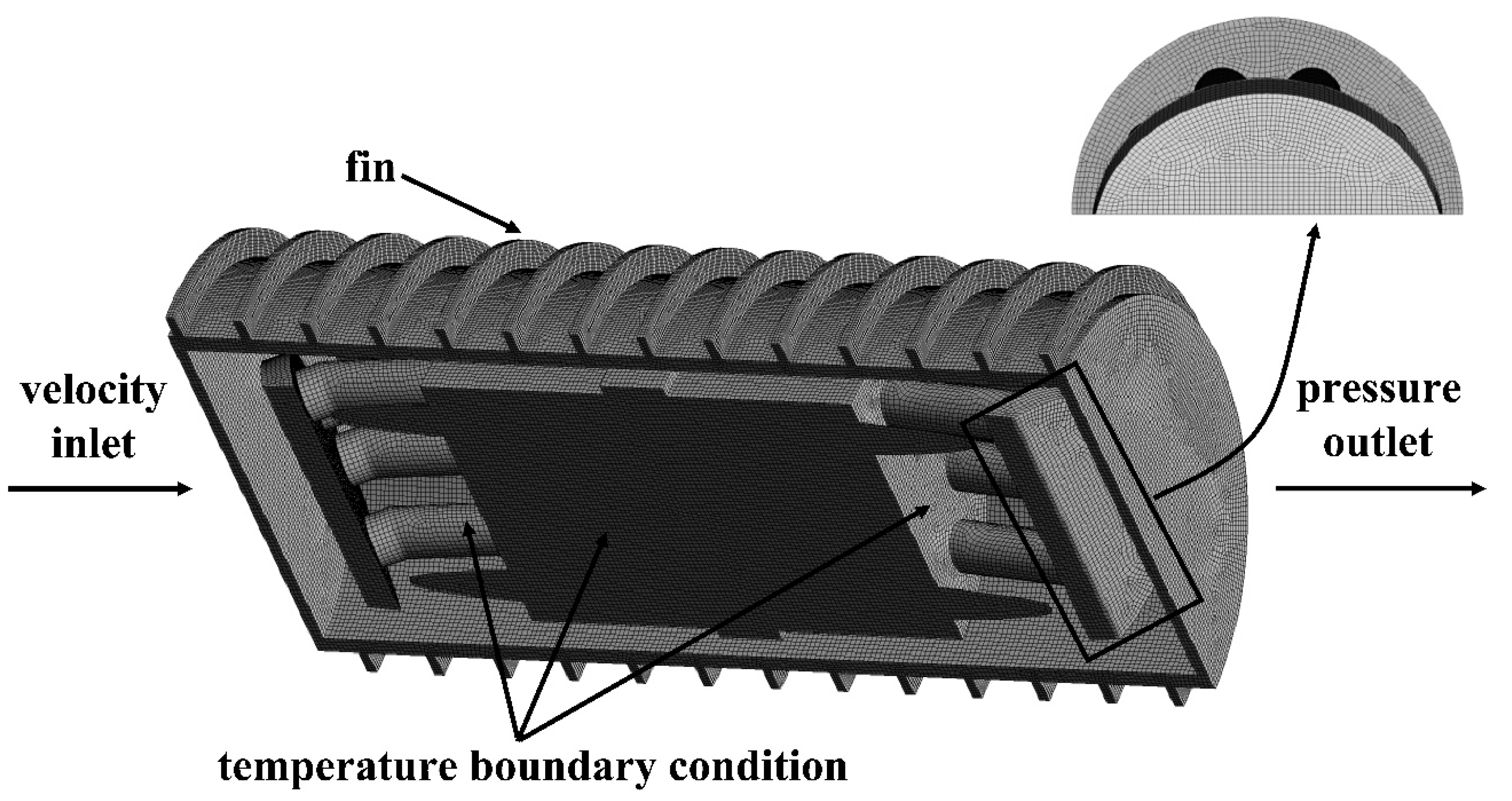
2.3. Mesh and Boundary Conditions

To exempt the inlet effects on hydraulic and thermal performance, the computational domain is extended by 150 mm at the inlet region. Similarly, it is extended by 450 mm at the outlet region in order to avoid backflow. To decrease the difficulty of meshing, some feature structures are not taken into consideration, including thread, chamfer, eyelet, and so on. The flow field is divided into four parts. Specifically, the entry section, outlet section, and the shell are meshed with structured mesh. Unstructured mesh is applied for the fin structure including quadrilateral mesh for surface and tetrahedral for body. To make sure the computational accuracy can come up to the standard, narrow space and area near the wall are dealt with grid refinement. An independence verification is depicted in Figure 4, showing the outlet temperature of model with three sets of grids. The number 1, 2, 3 refer to 4.17, 2.68, and 1.64 million cells, respectively, corresponding to finer-grid, fine-grid, and coarse condition. Figure 4a displays the outlet temperature condition under different sets of grid. The numerical uncertainty in the fine-grid solution with a cell number of 2.68 million ranges from 0.01% to 2.85%. When x/D equals to 0.25, the Grid Convergence Index (GCI) values are 2.85% and 2.10% for GCI32 and GCI21. After consideration, the fine-grid solution with a cell number of 2.68 million is dense enough for the grid independent solutions.
The steady thermal analysis of the shell is conducted on the assumption that the internal heat generation is the constant heat resource. Apart from this, further simplification is carried to receive the temperature distribution of the CCAPT considering the complexity of the structure and the flow field.
(1)
The CCAPT operates under the steady state, which means the volume loss and the mechanical loss are constant during the simulation.
(2)
Neglect the temperature differences between the shell and the internal rotating elements.
(3)
Take no account of the variance of the ambient temperature.
(4)
Leave out the pressure pulsation inside the CCAPT.
The numerical simulation is carried out in the software ANSYS FLUENT (Ansys, Canonsburg, PA, USA) supposing that the axial heat transfer of the shell has a negligible influence. The simulation model is presented in Figure 5, together with boundary conditions illustrated in the figure. The governing equations indicating continuity, momentum and energy conservation have been illustrated in published literature many times, which are not listed in the paper. Learn from Amiri et al. [30] and Alavi et al. [31], the heat transfer performance is investigated through the finite volume method on the basis of the Reynolds equation and the energy equation. Besides the Realizable κ-ε turbulence model, the SIMPLE algorithm is used for pressure-velocity coupling and the least square cell-based option for the spatial discretization of the gradient. In a gesture to calculate momentum, turbulent kinetic energy, turbulent dissipation rate and energy of the governing equations, the second order upwind scheme is utilized. Furthermore, the Presto scheme is applied for pressure interpolation. A no-slip condition is employed with respect to the wall while the standard wall function method is adopted with respect to the near-wall region.
The airflow enters the flow region in a state of uniformity with an inlet velocity of 3.5 m/s and a temperature of 300 K. The set of inlet boundary condition follows the recommendation of [33]. The material of fin can differ from that of shell. For the sake of convenience, here, both of them are selected as steel, possessing constant thermo-physical parameters, especially thermal conductivity. On the foundation of former research about the temperature distribution, Dirichlet condition is imposed on the inner surface of the shell with a constant temperature of 350 K, which is the maximum value of internal elements. With an ambient temperature of air ranges from 273.15 K to 323.15 K, the radiation heat transfer takes up less than 3% of the general heat dissipation [25]. To put it another way, the method of convection transfers more heat than radiation. Consequently, radiation is neglected in the simulation while heat transfers to the material through conduction and dissipates into the air by the means of convection.
Figure 6 illustrates the comparison between present data with experimental and correlational data from references [16,34,35,36]. In the Reynolds number range of 1867–4000, the maximum error between present data and simulation results [36] is 7.49%. In turbulent flow, the Colburn factor decreases with the increase of Reynolds number. When Re is larger than 30,000, the consistent variation trends and slopes of j factor can be observed from the figure. The correctness and validity of this work can be verified.

3. Results and Discussion

The irresistible development tendency for high-speed and high-pressure raises the difficulty of analyzing the interior flow field and temperature distribution. The thermal characteristics of the shell is the comprehensive result for internal heat generation and external heat dissipation. Hence, a good knowledge of internal thermal mechanisms and heat transfer paths would provide great guidance to the cooling structure design for the persistent pursuit of energy conservation and higher efficiency.

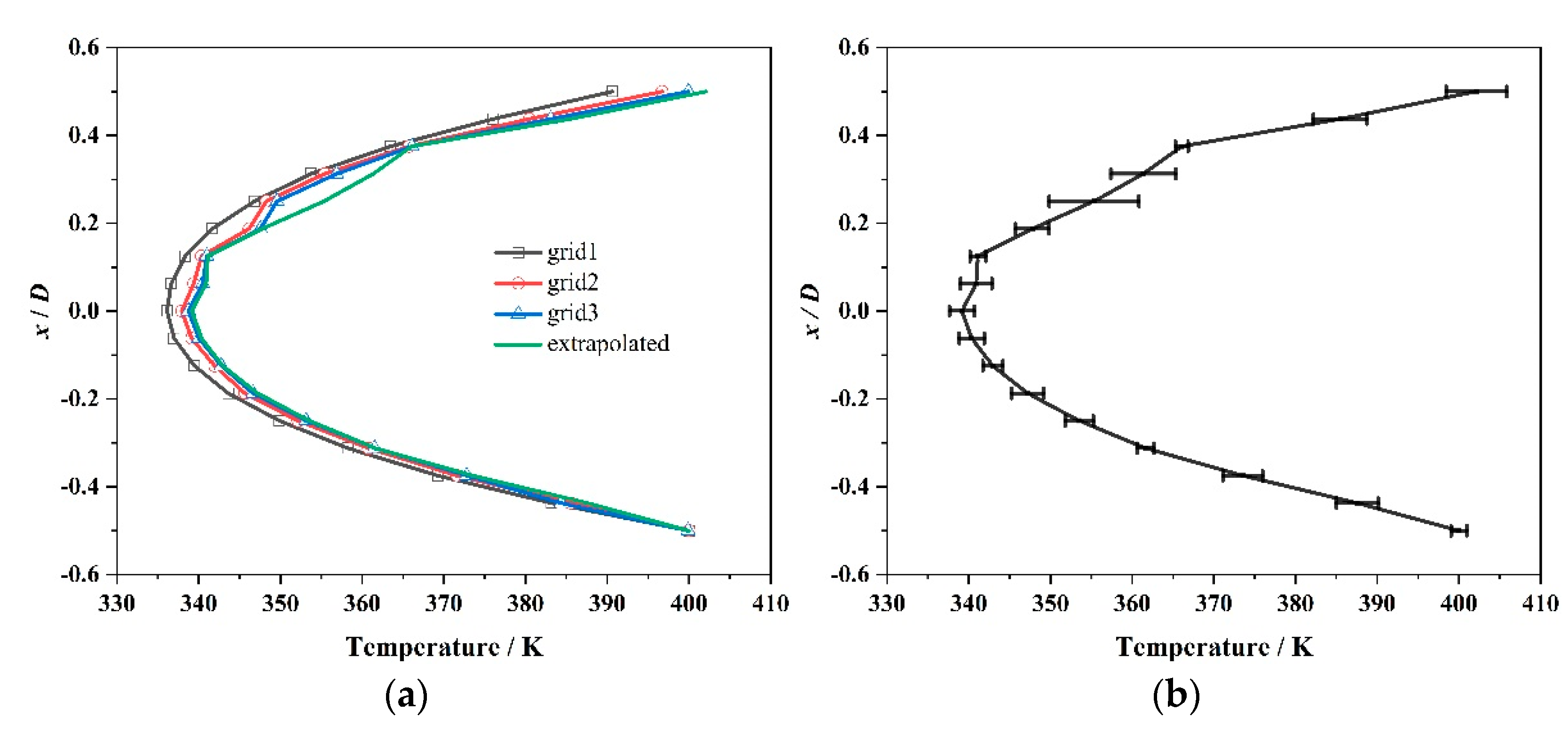
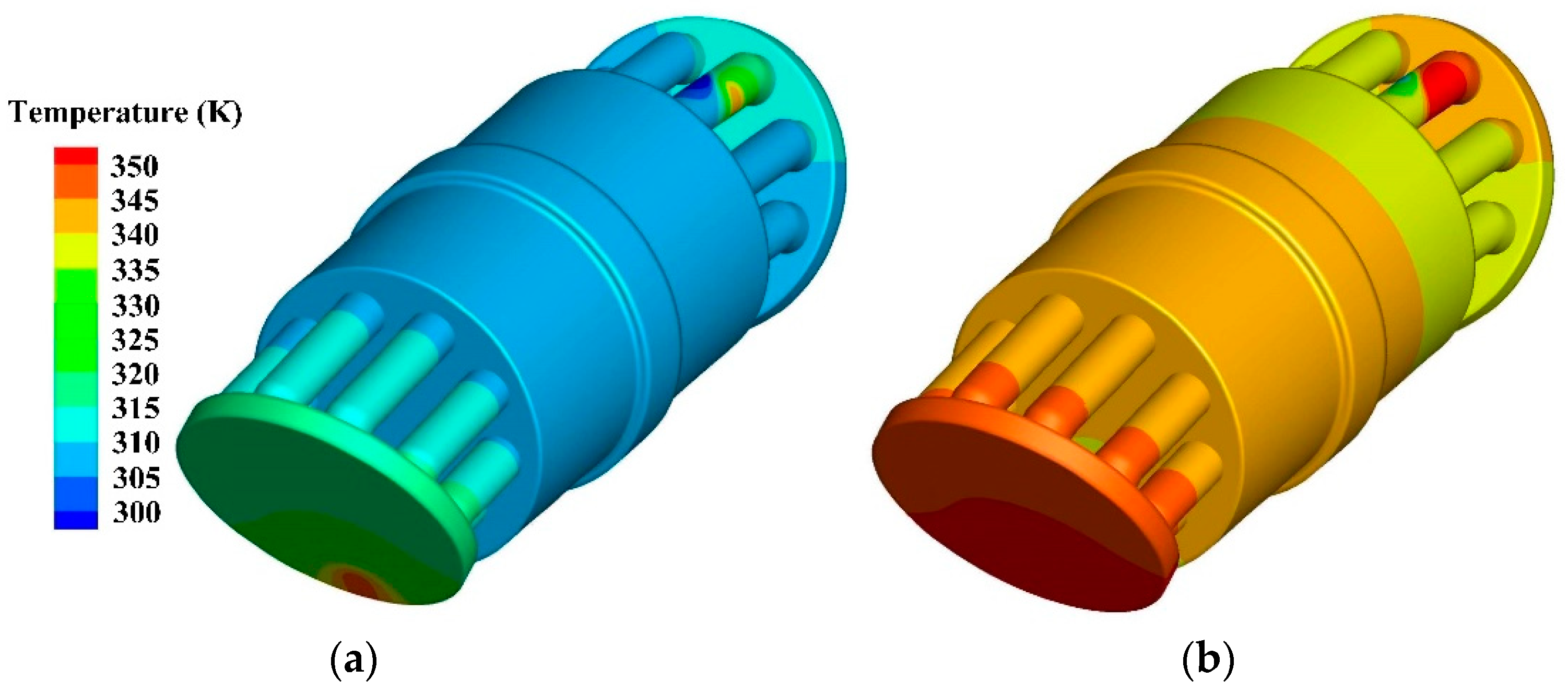
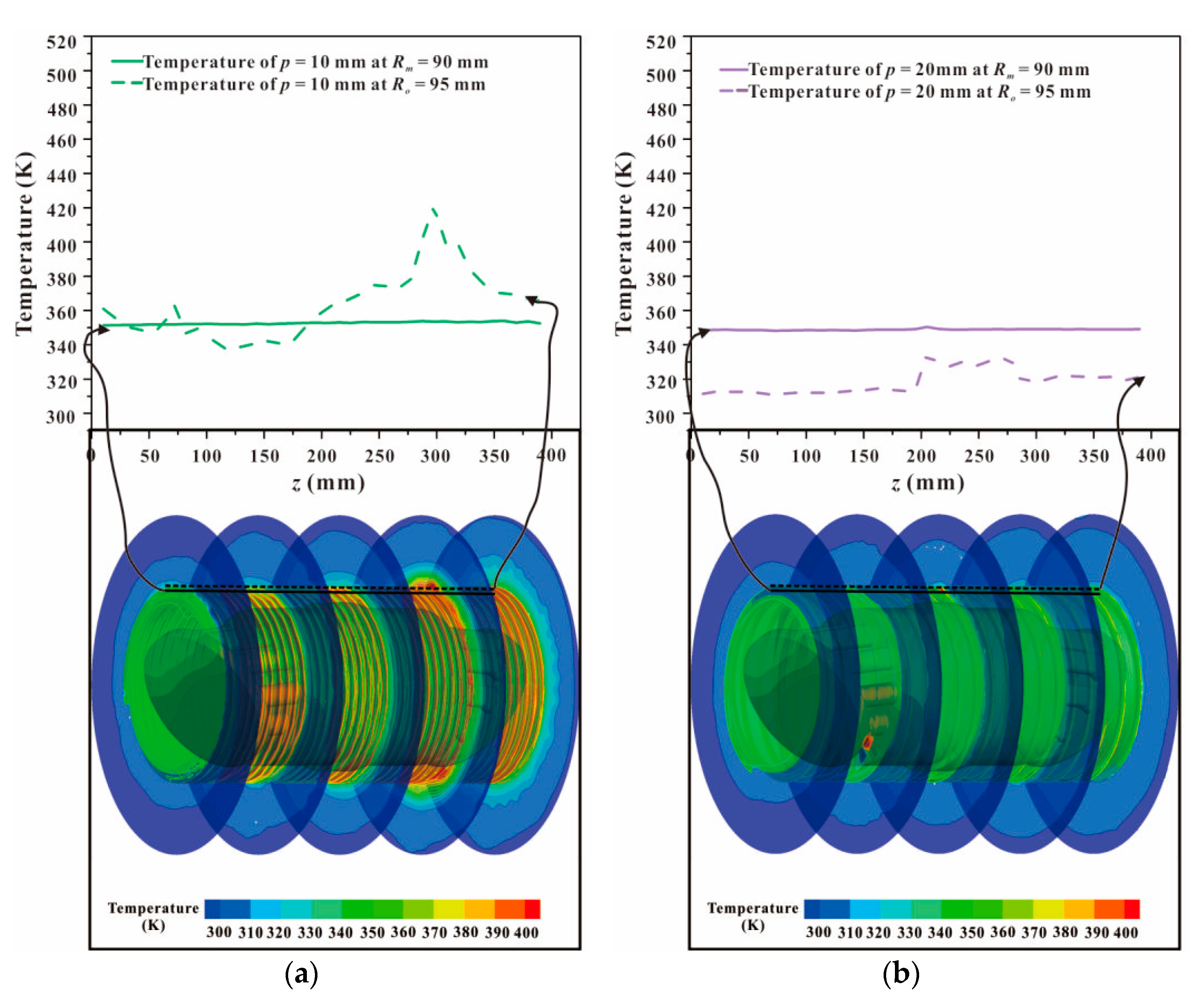
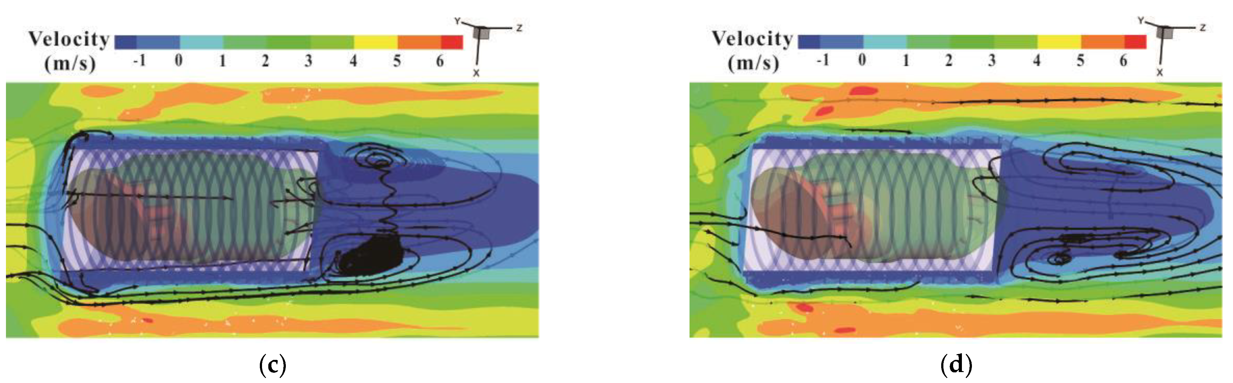
3.1. Temperature Distribution Inside the CCAPT

Assuming that all of the total power loss is converted into heat, the temperature rise of oil can be calculated according to the law of energy conservation. Results show that at the rated speed of 3500 r/min and the rated pressure of 60 MPa, the internal leakage loss is 249.78 W while the frictional power loss is 207.96 W concerning the valve plate-cylinder pair, giving rise to the temperature rise of 31.77 K. When it comes to the slipper-swash plate pair, the internal leakage loss is 7.97 W and the frictional power loss is 162.54 W, which brings about a temperature rise of 30.86 K. As to the piston-cylinder pair, the temperature rise is 17.25 K after calculation, arising from an internal leakage loss of 34.85 W and a frictional power loss of 143.44 W. The temperature rise induced by the rotating elements is less than 0.1 K, which is negligible compared with other kinds of heat generation.
At different rotating speeds, the internal heat generation varies and so does the corresponding temperature distribution. Although the maximum temperature differs, there is a resemblance between the regularities of temperature distribution. It can be seen from Figure 7 that around the slipper-swash plate pair, especially the contact region between the slipper and the swash plate, the temperature tends to be higher. The highest temperature about 350 K is achieved in this region. Compared with other kinds of friction pair, slipper-swash plate pair is the key factor affecting the development tendency of the axial piston pump with higher pressure, higher speed, and higher reliability. After entering the oil cavity of the slipper, the viscous dissipation of oil brings about heat generation and temperature rise.
During the flowing process, part of heat is taken away by oil, accompanied by the unceasing heat transfer and heat exchange. On the interface between the swash plate and oil film, as well as the contact surface between slipper and oil film, heat flows from the warmer to the cooler subject. The temperatures of the slipper and the swash plate increase after receiving part of heat. Heat dissipation takes place on the contact area between the outer surface of the machinery parts and the oil in the cavity of the shell.

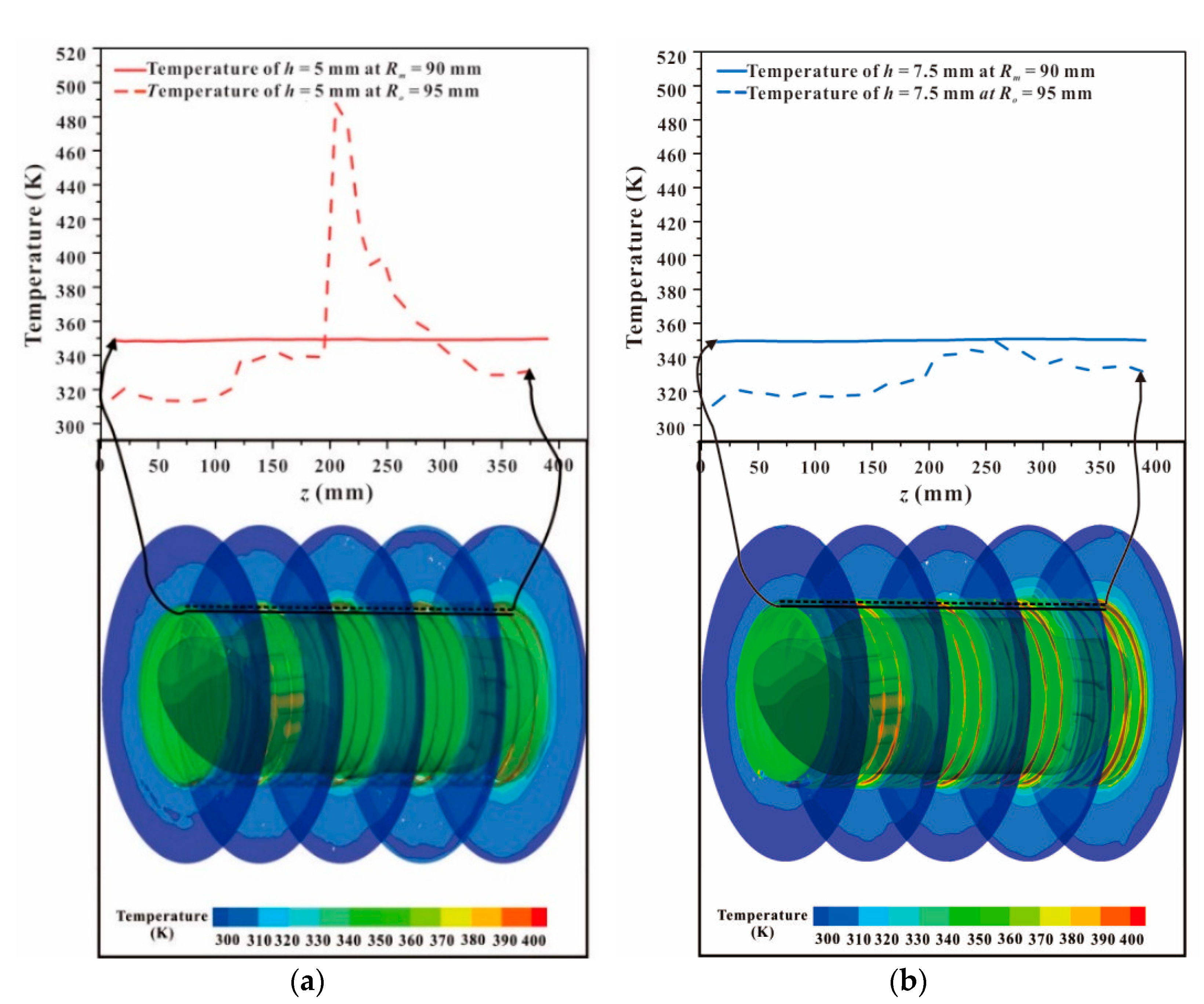
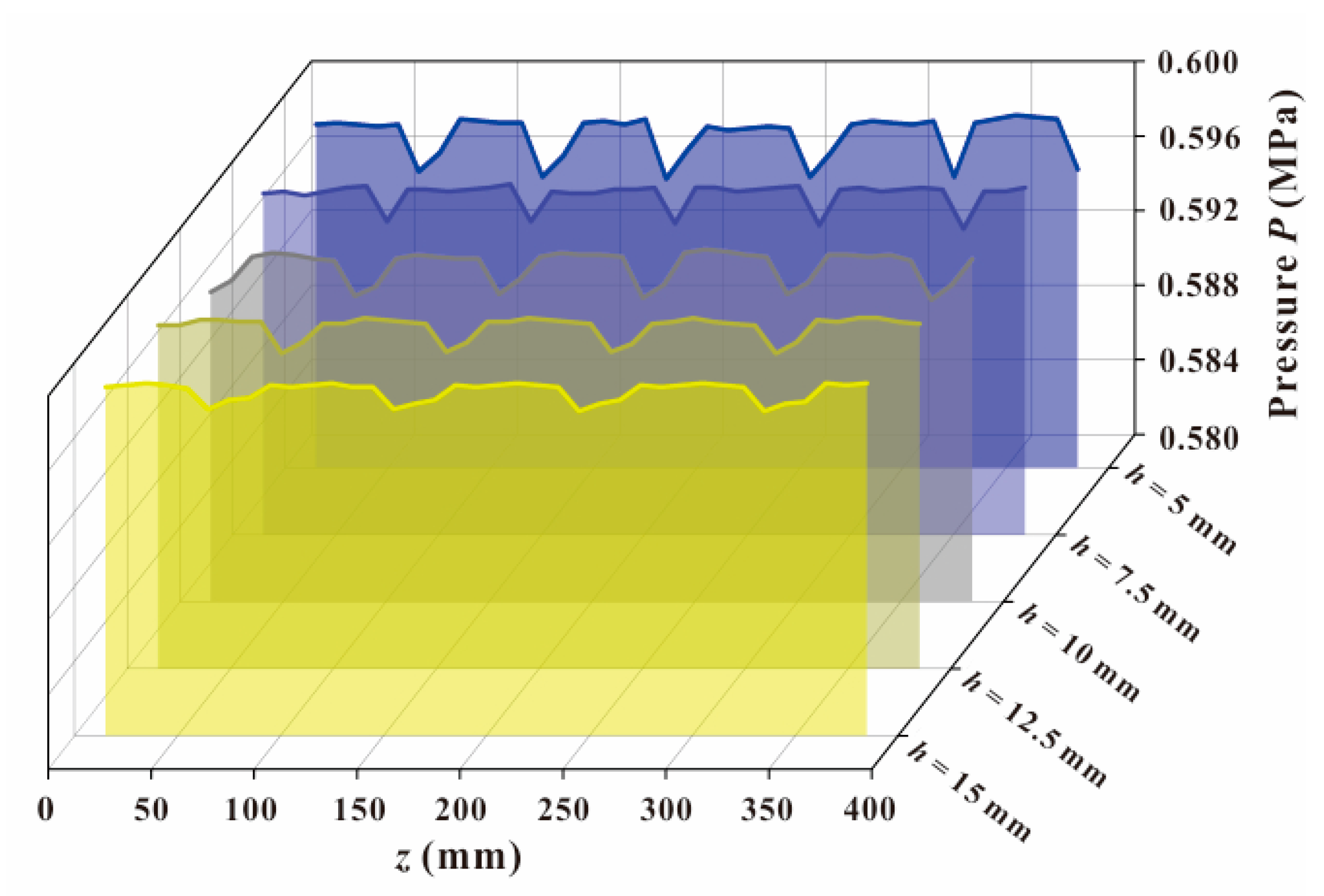
3.2. Effect of Fin Height h

The medium diameter Rm and outer diameter Ro of the CCAPT are 90 mm and 95 mm, respectively. Lines along the flow direction are extracted and temperatures at these two places are obtained. It can be inferred from Figure 8 that the temperatures at the medium diameter are subtle to distinguish, which are all around 350 K and the maximum difference is less than 2 K. As mentioned above, the inner wall of the shell is set as 350 K. Results indicate that the heat transfer along the axial direction has a negligible effect, which is in accordance with the assumption. The reality is that continuous heat is generated due to frictional loss and leakage loss. Hence, the source term is set up to fit the situation. The application of fins is beneficial to heat transfer but the exact effect depends on the arrangement and geometrical parameters. Most of the part has a temperature lower than that of the inner surface. The areas with temperature higher than 350 K accumulate more heat inside the CCAPT. To put it another way, the difficulty of reaching thermal equilibrium increases in these regions.
Compared with the condition of h = 5 mm, the temperature distribution of the shell gets improved and the highest value decreases dramatically when fin height equals to 7.5 mm. The place where peak value appears transfers from z = 205 mm to z = 256 mm. It is worth mentioning that both of them correspond to the region of rotating elements. The surface temperatures of the fin structure in Figure 8a,b follow similar distribution pattern, and so are the air flow fields in the out-side of the shell because the variance of fin height is limited compared with the size of the CCAPT. The increase of the pitch height results in the expansion of heat transfer area, and heat dissipation can be promoted consequently. However, the commercial value of this method should undergo critical assessment.
The pressure condition of the models along the flow direction can be seen in Figure 9, which reflects the average pressure of the cross-sections. They are designed with different fin height ranging from 5 mm to 15 mm when the pitch and the thickness are 20 mm and 2 mm, respectively. There exists periodic variation in the figure and the minimum value appears at intervals which can be attributed to the periodic flow of air. The fin height affects the pressure value to some extent. With the increase of fin height, the periodic length gets longer and the transition becomes smoother.
Generally, the turbulent intensity will be more intense when the fin height increases. Accordingly, the heat transfer augmentation promotes the cooling process of the shell. Although there may exist partial high temperature, but the peak value decreases and the coverage area shrinks. In other words, the heat dissipation effects get improved.
As illustrated in Table 2, the largest Nusselt number and Colburn factor are obtained with fin height h = 7.5 mm. When fin height increases from 10 mm to 15 mm, heat transfer coefficient increases, together with the Colburn factor. In other words, the best heat dissipation effect is achieved when fin height equals to 7.5 mm, almost 2.09 times that of the condition without the fin structure.

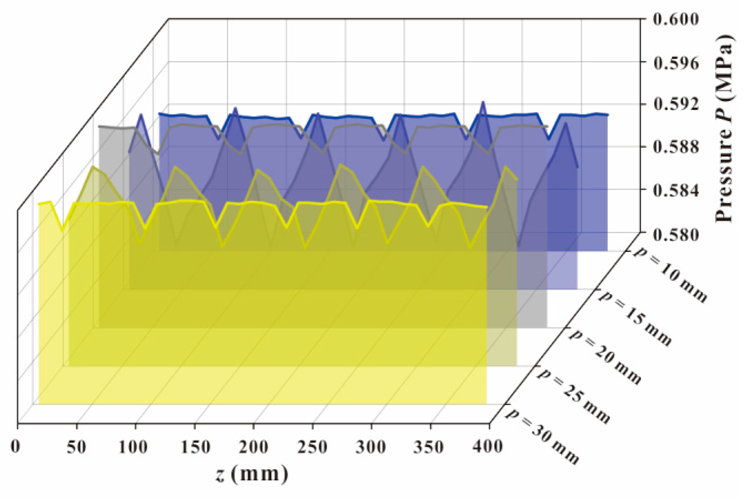
3.3. Effect of Fin Pitch p

Figure 10 displays the temperatures at medium diameter and outer diameter along the z-axis with constant value of fin height and thickness. When the pitch equals to 10 mm, the maximum temperature at outer diameter reaches 420.60 K near the piston-cylinder pair. Most of the parts are higher than 350 K and the high temperature region above 380 K exists about 50 mm. For comparison purpose, the temperature of pitch p = 20 mm is also given in Figure 10b. The range of the temperature variation is smaller and all the temperatures at the outer diameter are below 350 K. Similarly, the surface temperature of fins is lower than that of the condition with pitch p = 10 mm, which is illustrated in the temperature distribution contour. From a quantitative perspective, the heat dissipation effect of the condition with larger pitch is better. The heat exchange between cooling air and shell is insufficient when pitch equals to 10 mm. When pitch increases to 20 mm, the complete destruction of the temperature boundary layer and the velocity boundary layer enhances the efficiency of the convective heat transfer process.
The phenomenon of velocity separation appears in the outlet region of the CCAPT, where a wake region of large area is created, together with the conspicuous vortex. In this section, the velocity of air flow is small compared with other regions, as depicted in Figure 11. Apart from this, a part of air flows in the opposite direction of the mainstream, the velocity of which is in the form of negative value. Owing to the existence of the wake region, the enhancement of heat transfer gets diminished. The alteration of pitch results in the difference of velocity distribution and the wake region remains however the pitch changes. The area of the wake region reaches the maximum with a pitch of 15 mm.
Figure 12 depicts the pressure change along the flow direction with the increase of pitch from 10 mm to 30 mm. The ranges of variation alter with the difference of pitch when fin height and fin thickness equal to 10 mm and 2 mm, respectively. With a pitch of 15 mm, the pressure variance in a period experiences a more drastic change, which raises 4.8 times that of the condition with a pitch of 10 mm. The heterogeneous distribution of air gives rise to the non-uniform pressure field, affecting the heat transfer efficiency at the same time. When pitch increases up to 30 mm, the pressure distribution resembles that of the condition with a pitch of 10 mm but with higher values and shorter periodic length.
Table 3 demonstrates Nu and j under different fin pitch. With an increase in fin pitch, Nusselt number increases, indicating a better heat transfer performance. In the scope of research, the peak value of Nu is achieved with fin pitch p = 30 mm, which increases 104.27% over the original case without fin structure. When it comes to the Colburn factor, it also keeps growing when the fin pitch increases from 10 mm to 30 mm, when the fin height and thickness are consistent with other conditions. To put it another way, the best comprehensive performance is realized at p = 30 mm.

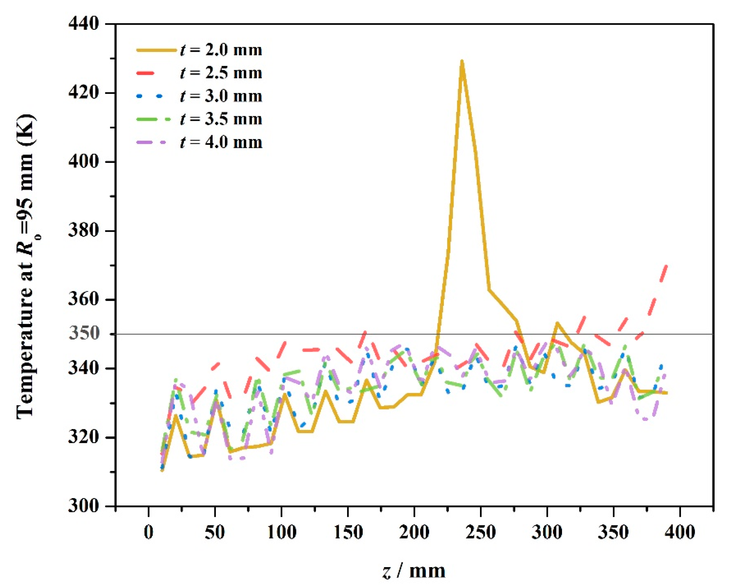
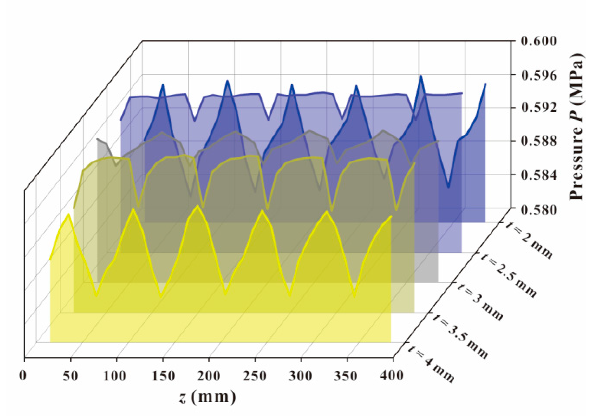
3.4. Effect of Fin Thickness t

Within the variation of fin thickness ranging from 2 mm to 4 mm, the temperature at the outer diameter is extracted along the z-axis with a fin height of 10 mm and a pitch of 15 mm. In consistence with the previous investigation, the average temperature at the medium diameter is approximately 350 K, which is plotted and painted with gray in Figure 13. The peak value emerges in the area near rotating elements. It can be inferred from aforementioned statements that the region between 200 mm and 300 mm tends to accumulate more heat in previous statements. The temperature distribution in Figure 13 is in agreement with the conclusion. To improve the heat dissipation efficiency and obtain thermal equilibrium as soon as possible, more attention should be paid on this part. In spite of the condition with fin thickness t = 2 mm, most of other lines are below 350 K. The thicker the fin is, the better the heat dissipation effect is. The average temperature at the outer diameter of the condition with thickness t = 4 mm is 335.26 K, 2.57% lower than that of the worst condition. Although the discrepancy in average value is subtle, the figure is still a reflection of the uniformity in the temperature field.
Figure 14 reveals the pressure change along the flow direction, containing the conditions of thickness t = 2 mm, 2.5 mm, 3 mm, 3.5 mm, and 4 mm. The fin height and fin pitch are set at fixed values of 10 mm and 15 mm, respectively. With a thickness of 2 mm, the pressure change experiences the largest range of variation in pressure, as an indication for the inhomogeneous flow field. The length of the period decreases with the increase of the fin thickness. Considering that the focus of the investigation is the heat dissipation effect and attention is paid to the thermal performance of the fin structure, the pressure of the inlet region and the outlet region is not displayed in the figure. Consequently, the pressure drop is not calculated in this research, which is a valuable parameter for structure optimization.

4. Conclusions

In this research, a spiral fin structure is applied to the shell side of the CCAPT to improve its heat transfer characteristic and prolong its service life. Given the heat path of the device and internal temperature distribution condition, a thermodynamic model is constructed with the help of the finite volume method. The effects of fin height h, fin pitch p, and fin thickness t on the thermal performance are studied during the investigation. Results indicate that the moderate increase of fin height can decrease the peak value of the surface temperature and reduce the coverage area of temperature over 350 K. The best heat dissipation effect is realized with fin height h = 7.5 mm in the scope of research. Both Nusselt number and Colburn factor increase with the increase of pitch. When pitch equals to 30 mm, the heat transfer coefficient is almost twice that of the condition without fin structure. In the range of 2 mm to 4 mm, the thicker the fin is, the better the heat dissipation effect.

Author Contributions

Conceptualization: C.Y. and J.-y.Q.; methodology: J.Z. and J.-y.Q.; software: C.Y.; validation: L.-j.Y.; formal analysis: C.Y.; investigation: C.Y.; resources: C.Y.; data curation: C.Y.; writing—original draft preparation: C.Y.; writing—review and editing: J.Z. and L.-j.Y.; visualization: C.Y.; supervision: J.Z. and J.-y.Q.; project administration: J.Z. and J.-y.Q.; funding acquisition: J.Z. and J.-y.Q. All authors have read and agreed to the published version of the manuscript.

Funding

This research was funded by the National Natural Science Foundation of China (NSFC), grant number 51922093; the National Key Research and Development Program, grant number 2019YFB2005101; and the Youth Funds of the State Key Laboratory of Fluid Power and Mechatronic Systems, grant number SKLoFP-QN-1801.

Institutional Review Board Statement

Not applicable.

Informed Consent Statement

Not applicable.

Data Availability Statement

Not applicable.

Conflicts of Interest

The authors declare no conflict of interest.

Abbreviations

AaTotal heat transfer areamm2
AcfHeat transfer area between the shell and fluidsmm2
AchHeat transfer area between the shell and environmentsmm2
AcsContact area between rotating area and the shellmm2
AfArea of the fin structuremm2
AsfHeat transfer area between rotating element and fluidmm2
CpSpecific heat capacityJ·kg−1·K−1
dcfCharacteristic diameter of the inner surfacemm
GrGrashof number
hFin heightmm
hiHeat transfer coefficientW·m−2·K−1
hcThickness of pump shellmm
jColburn factor
kfThermal conductivity of the material of the fin structureW·m−2·K−1
lHalf the length of the fin heightmm
NuNusselt number
NuxLocal Nusselt number
pPitchmm
PPressurePa
PrPrandtl number
QHeat transfer quantityJ
Q c f Convective heat transfer rate between the shell and fluidsW
Q c h 1 Convective heat transfer rate between the shell and surroundingsW
Q c s Heat transfer rate of thermal conduction between rotating element and systemW
Q c h 2 Radiative heat transfer rate between the shell and ambient environmentW
Q s f Heat transfer rate of forced convection between the rotating element and fluidW
ReReynolds number
TcnTemperature of inner surfaceK
TcwTemperature of outer surfaceK
TfTemperature of fluidK
ThTemperature of environmentK
TsSurface temperature of rotating elementK
tFin thicknessmm
uVelocitym·s−1
Greek symbols
εBlackness of shell material
αcfConvection coefficient between the shell and fluidsW·m−2·K−1
αchfConvection coefficient between the shell and surroundingsW·m−2·K−1
αsfConvective heat transfer coefficient between rotating elements and fluidW·m−2·K−1
η0Surface coefficient of the fin
ηfFin efficiency
λThermal conductivityW·m−1·K−1
ρDensitykg/m3
σThe Stefan-Boltzmann constantW·m−2·K−4
ΔPPressure differencePa
ΔTLMTDLogarithm mean temperature differenceK

References

  1. Wang, Z.W.; Wang, L.; Ma, A.H.; Liang, K.F.; Song, Z.; Feng, L.W. Performance evaluation of ground water-source heat pump system with a fresh air pre-conditioner using ground water. Energy Convers. Manag. 2019, 188, 250–261. [Google Scholar] [CrossRef]
  2. Sergey, A. System of energy-saving optimal control of metal heating process in heat treatment furnaces of rolling mills. Machines 2019, 7, 60. [Google Scholar]
  3. Harish, S.; Simone, B. A novel modelling approach for condensing boilers based on hybrid dynamical systems. Machines 2016, 4, 10. [Google Scholar]
  4. Muhammad, S.U.Z.; Raza, H.; Syed, B.A.B.; Hafiz, M.A.; Chul-Hwan, K. Impacts of responsive loads and energy storage system on frequency response of a multi-machine power system. Machines 2019, 7, 1–15. [Google Scholar]
  5. Gao, D.R.; Zhang, Z.Y.; Sun, Y.N.; Xu, S.H.; Liu, J.C.; Zhang, Y. Numerical simulation and analysis of temperature and flow field of high-speed axial piston motor pump. J. Eng. 2019, 13, 127–131. [Google Scholar] [CrossRef]
  6. Chen, H.; Peng, Y.H.; Wang, Y.L.; Zhang, J. Thermodynamic analysis of hybrid cooling system integrated with waste heat reusing and peak load shifting for data center. Energy Convers. Manag. 2019, 183, 427–439. [Google Scholar] [CrossRef]
  7. Chan, M.A.; Yap, C.R.; Ng, K.C. Modeling and testing of an advanced compact two-phase cooler for electronics cooling. Int. J. Heat Mass Transf. 2009, 52, 3456–3463. [Google Scholar] [CrossRef]
  8. Alexey, N.; Innokentiy, S.; Igor, S. The setup design for selective laser sintering of high-temperature polymer materials with the alignment control system of layer deposition. Machines 2018, 6, 11. [Google Scholar]
  9. Amber, K.P.; Akram, W.; Bashir, M.A.; Muhammad, S.K.; Anila, K. Experimental performance analysis of two different passive cooling techniques for solar photovoltaic installations. J. Therm. Anal. Calorim. 2020. [Google Scholar] [CrossRef]
  10. Pongsoi, P.; Pikulkajorn, S.; Wang, C.C.; Wongwises, S. Effect of number of tube rows on the air-side performance of crimped spiral fin-and-tube heat exchangers with a multipass parallel and counter cross-flow configuration. Int. J. Heat Mass Transf. 2012, 55, 1403–S1411. [Google Scholar] [CrossRef]
  11. Dezan, D.J.; Yanagihara, J.I.; Jenovencio, G.; Leandro, O.S. Parametric investigation of heat transfer enhancement and pressure loss in louvered fins with longitudinal vortex generators. Int. J. Therm. Sci. 2019, 135, 533–545. [Google Scholar] [CrossRef]
  12. Kim, N.H. Airside performance of fin-and-tube heat exchangers having nonrepeating nonsymmetrical slit fins under wet condition. Int. J. Air-Cond. Refrig. 2019, 27, 1950033. [Google Scholar] [CrossRef]
  13. Shadlaghani, A.; Farzaneh, M.; Shahabadi, M. Numerical investigation of serrated fins on natural convection from concentric and eccentric annuli with different cross sections. J. Therm. Anal. Calorim. 2018, 135, 1429–1442. [Google Scholar] [CrossRef]
  14. Alsallami, W.; Aldamook, A.; Thompson, H.M. A numerical investigation of the thermal-hydraulic characteristics of perforated plate fin heat sinks. Int. J. Therm. Sci. 2017, 121, 266–277. [Google Scholar] [CrossRef] [Green Version]
  15. Lee, M.; Kang, T.; Kim, Y. Air-side heat transfer characteristics of spiral-type circular fin-tube heat exchangers. Int. J. Refrig. 2010, 33, 313–320. [Google Scholar] [CrossRef]
  16. Kim, N. An experimental investigation on the airside performance of fin-and-tube heat exchangers having radial slit fins under wet condition. Int. J. Therm. Sci. 2016, 11, 1–17. [Google Scholar] [CrossRef] [Green Version]
  17. Pongsoi, P.; Promoppatum, P.; Pikulkajorn, S.; Wongwises, S. Effect of fin pitches on the air-side performance of L-footed spiral fin-and-tube heat exchangers. Int. J. Heat Mass Transf. 2013, 59, 75–82. [Google Scholar] [CrossRef]
  18. Nørgård, J. Thermodynamic determination of power loss in hydraulic components. J. Fluids Eng. 1973, 95, 2–7. [Google Scholar] [CrossRef]
  19. Olems, L. Investigations of the Temperature behaviour of the piston cylinder assembly in axial piston pumps. Int. J. Fluid Power 2000, 1, 27–39. [Google Scholar] [CrossRef]
  20. Iboshi, N.; Yamaguchi, A. Characteristics of a slipper bearing for swash plate type axial piston pumps and motors: 1st report, theoretical-analysis. JSME Int. J. Ser. B-Fluids Therm. Eng. 1982, 25, 1921–1930. [Google Scholar] [CrossRef] [Green Version]
  21. Iboshi, N. Characteristics of a slipper bearing for swash plate type axial piston pumps and motors: 2nd report, experiment. JSME Int. J. Ser. B-Fluids Therm. Eng. 1983, 26, 1583–1589. [Google Scholar] [CrossRef] [Green Version]
  22. Iboshi, N.; Yamaguchi, A. Characteristics of a slipper bearing for swash plate type axial piston pumps and motors: 3rd report, design method for a slipper with a minimum power loss in fluid lubrication. JSME Int. J. Ser. B-Fluids Therm. Eng. 1986, 29, 2529–2538. [Google Scholar] [CrossRef] [Green Version]
  23. Xu, B.; Wang, Q.N.; Zhang, J.H. Effect of case drain pressure on slipper/swashplate pair within axial piston pump. J. Zhejiang Univ.-Sci. A 2015, 16, 1001–1014. [Google Scholar] [CrossRef]
  24. Wieczorek, U.; Monika, I. Computer aided optimization of bearing and sealing gaps in hydrostatic machines—the simulation tool caspar. Int. J. Fluid Power 2002, 3, 7–20. [Google Scholar] [CrossRef]
  25. Li, D.L.; Li, G.Q.; Han, J.H.; Liu, Y.S.; Wu, D.F. Thermodynamic characteristics research of a water lubricating axial piston pump. Proc. Inst. Mech. Eng. C-J. Mech. 2020. [Google Scholar] [CrossRef]
  26. Xu, B.; Hu, M.; Zhang, J.H.; Mao, Z.B. Distribution characteristics and impact on pump’s efficiency of hydro-mechanical losses of axial piston pump over wide operating ranges. Cent. South Univ. 2017, 24, 609–624. [Google Scholar] [CrossRef]
  27. Xu, B.; Hu, M.; Zhang, J.H.; Su, Q. Characteristics of volumetric losses and efficiency of axial piston pump with respect to displacement conditions. J. Zhejiang Univ.-Sci. A 2016, 17, 186–201. [Google Scholar] [CrossRef] [Green Version]
  28. Ye, S.; Zhang, J.; Xu, B.; Zhu, S.; Xiang, J.; Tang, H. Theoretical investigation of the contributions of the excitation forces to the vibration of an axial piston pump. Mech. Syst. Signal Process. 2019, 129, 201–217. [Google Scholar] [CrossRef]
  29. Ye, S.; Zhang, J.; Xu, B.; Hou, L.; Xiang, J.; Tang, H. A theoretical dynamic model to study the vibration response characteristics of an axial piston pump. Mech. Syst. Signal Process. 2021, 150, 107237. [Google Scholar] [CrossRef]
  30. Amiri, H.A.; Shafaghat, R.; Alamian, R.; Taheri, S.M.; Shadloo, M.S. Study of horizontal axis tidal turbine performance and investigation on the optimum fixed pitch angle using CFD. Int. J. Numer. Method Heart 2020, 30, 206–227. [Google Scholar] [CrossRef]
  31. Alavi, S.M.A.; Safaei, M.R.; Mahian, O.; Goodarzi, M.; Yarmand, H.; Dahari, M.; Wongwises, S. A hybrid finite-element/finite-difference scheme for solving the 3-d energy equation in transient nonisothermal fluid flow over a staggered tube bank. Numer. Heat Transf. B-Fundam. 2015, 68, 169–183. [Google Scholar] [CrossRef] [Green Version]
  32. Roberto, M. Pollutant emission validation of a heavy-duty gas turbine burner by CFD modeling. Machines 2013, 1, 81–97. [Google Scholar]
  33. Nemati, H.; Moghimi, M.A.; Sapin, P.; Markides, C.N. Shape optimisation of air-cooled finned-tube heat exchangers. Int. J. Therm. Sci. 2020, 150, 106233. [Google Scholar] [CrossRef]
  34. Briggs, D.E.; Young, E.H. Convective heat transfer and pressure drop of air flowing across triangular pitch banks of finned tubes. Chem. Prog. Eng. Symp. Ser. 1963, 59, 1–10. [Google Scholar]
  35. Kim, N.H.; Ham, J.H.; Cho, J.P. Experimental investigation on the airside performance of fin-and-tube heat exchangers having herringbone wave fins and proposal of a new heat transfer and pressure drop correlation. J. Mech. Sci. Technol. Convers. Manag. 2008, 22, 545–555. [Google Scholar] [CrossRef]
  36. Kumar, A.; Joshi, J.B.; Nayak, A.K. A comparison of thermal-hydraulic performance of various fin patterns using 3D CFD simulations. Int. J. Heat Mass Transf. 2017, 109, 336–356. [Google Scholar] [CrossRef]
Figure 1. The schematic view of the closed circuit axial piston transmission.
Machines 09 00017 g001
Figure 2. Geometric details and schematic diagram from (a) front view; (b) sectional view.
Machines 09 00017 g002
Figure 3. A schematic diagram of the heat transfer path.
Machines 09 00017 g003
Figure 4. Grid independence of the fin structure including (a) outlet temperature under three sets of grids; (b) discretization error.
Machines 09 00017 g004
Figure 5. Simulation model and boundary conditions.
Machines 09 00017 g005
Figure 6. Comparison with Colburn factor with data from references.
Machines 09 00017 g006
Figure 7. The temperature distribution of machinery elements inside the axial piston pump at (a) rotating speed of 3000 r/min; (b) rotating speed of 3600 r/min.
Machines 09 00017 g007
Figure 8. Temperature distribution with a fin pitch p = 20 mm and fin thickness t = 2 mm when (a) fin height h = 5 mm; (b) height = 7.5 mm.
Machines 09 00017 g008
Figure 9. Pressure distribution with a fin pitch p = 20 mm and fin thickness t = 2 mm.
Machines 09 00017 g009
Figure 10. Temperature distribution with a fin height h = 10 mm and fin thickness t = 2 mm when (a) fin pitch p = 10 mm; (b) fin pitch p = 20 mm.
Machines 09 00017 g010
Figure 11. Velocity distribution with a fin height h = 10 mm and fin thickness t = 2 mm when (a) fin pitch p = 10 mm; (b) fin pitch p = 15 mm; (c) fin pitch p = 20 mm; (d) fin pitch p = 25 mm.
Machines 09 00017 g011aMachines 09 00017 g011b
Figure 12. Pressure distribution with a fin height h = 10 mm and fin thickness t = 2 mm.
Machines 09 00017 g012
Figure 13. Temperature distribution with a fin height h = 10 mm and fin pitch p = 15 mm.
Machines 09 00017 g013
Figure 14. Pressure distribution with a fin height h = 10 mm and fin pitch p = 15 mm.
Machines 09 00017 g014
Table 1. Physical properties of material for shell of CCAPT.
MaterialPump HousingMotor Housing
40CrZL105
Density/(kg m−3)78202680
Specific heat capacity/(J kg−1 K−1)460837
Thermal conductivity/(W m−1 K−1)32.6163.3
Table 2. Nusselt number and Colburn factor under different fin height h.
Fin Height (mm)Nuj (10−3)
5.089.021.77
7.5108.271.81
10.093.751.79
12.581.021.77
15.074.611.73
without fin structure51.76-
Table 3. Nusselt number and Colburn factor under different fin pitch p.
Fin Pitch (mm)Nuj (10−3)
1083.751.72
1587.131.75
2093.751.79
2599.421.80
30105.731.83
without fin structure51.76-
Publisher’s Note: MDPI stays neutral with regard to jurisdictional claims in published maps and institutional affiliations.

