Article

Investigation on Finishing Characteristics of Magnetic Abrasive Finishing Process Using an Alternating Magnetic Field

Graduate School of Engineering, Utsunomiya University, 7-1-2 Yoto, Utsunomiya, Tochigi 321-8585, Japan
*
Author to whom correspondence should be addressed.
Machines 2020, 8(4), 75; https://doi.org/10.3390/machines8040075
Submission received: 15 October 2020 / Revised: 12 November 2020 / Accepted: 13 November 2020 / Published: 16 November 2020
(This article belongs to the Special Issue Advanced Autonomous Machines and Designs)

Abstract

:
The magnetic abrasive finishing (MAF) process is an ultra-precision surface finishing process. In order to further improve the finishing efficiency and surface quality, the MAF process using an alternating magnetic field was proposed in the previous research, and it was proven that the alternating magnetic field has advantages compared with the static magnetic field. In order to further develop the process, this study investigated the effect on finishing characteristics when the alternating current waveform is a square wave. The difference between the fluctuation behavior of the magnetic cluster in two alternating magnetic fields (sine wave and square wave) is observed and analyzed. Through analysis, it can be concluded that the use of a square wave can make the magnetic cluster fluctuate faster, and as the size of the magnetic particles decreases, the difference between the magnetic cluster fluctuation speed of the two waveforms is greater. The experimental results show that the surface roughness of SUS304 stainless steel plate improves from 328 nm Ra to 14 nm Ra within 40 min.

1. Introduction

The corrosion and fatigue failure of machine elements undoubtedly cause huge financial losses. Excellent surface quality can improve the corrosion resistance [1] and fatigue strength [2] of the material to a certain extent. In addition, for some precision machinery, surface finish is also an important factor that is indispensable to perform its functions. Traditional finishing methods to achieve nano-level surface finish usually lead to a significant increase in production costs [3]. The magnetic abrasive finishing (MAF) process is considered to be an effective method to improve the surface finish. The grinding tool of the MAF process is the magnetic brush composed of tiny particles combined under the action of the magnetic field [4,5]. The MAF process realizes the material removal (MR) by the relative movement of these tiny particles and the workpiece [6,7]. In addition, due to the flexibility of the magnetic brush, it can be applied to the finishing of complex surfaces, such as curved surfaces [8] and groove inner surfaces [9]. The advantages of the MAF process are attracting more people to discuss.
Shinmura et al. [10,11] discussed the MAF process in the early years. The basic principle of the MAF process is clarified, and the finishing characteristics are discussed. Zou et al. [12,13] proposed a method to improve the surface uniformity by changing the trajectory of the magnetic pole. Through the analysis of the particle movement trajectory, they concluded that the magnetic pole revolution movement can effectively improve the uniformity of the finished surface, which was verified by experiments. In addition, they discussed the finishing characteristics and finishing stability of magnetic abrasive finishing combined with the electrolytic process (EMAF) [14,15]. They concluded that under suitable conditions, the finishing efficiency of EMAF process is higher than that of MAF. Yin et al. [16,17] proposed a vibration-assisted MAF process. They discussed in detail the effects of the three modes (horizontal vibration, vertical vibration, and compound vibration) on the finishing characteristics, and analyzed the finishing mechanism. It proves that the vibration-assisted MAF process can achieve effective polishing of 3D micro-curved surfaces. Jain et al. [18] evaluated the influence of working clearance and circumferential speed on finishing characteristics and showed that the material removal rate will decrease with the increase in working clearance or the decrease of workpiece circumferential speed. Yamaguchi et al. [19,20] discussed the internal finishing of the tube by the MAF process. They showed that the MAF process can effectively improve the internal surface quality of the tube. Kala et al. [21] studied the effect of changing speed and working gap on machining force on a dual-disk magnetic abrasive polishing process. They showed that the normal force and the tangential force increase with the decrease of the working gap, and the magnitude of the normal force and the tangential force will decrease sharply when the rotation speed is higher than a certain value. Mulik and Pandey [22] studied the modeling of finishing force in the ultrasonic-assisted magnetic abrasive finishing process. The normal force and finishing torque were measured under several process conditions. It has been shown that the gap and the power supply voltage are the main factors affecting the finishing force. A mathematical model has been established to predict the finishing force and torque, and verify it through experimental results. Lee et al. [23,24] discussed the influence of the two-dimensional vibration-assisted MAF process on the finishing efficiency and surface quality. They proved that this method helps to improve finishing efficiency and surface quality. Moreover, through Taguchi experimental design, the best combination of process parameters to improve surface roughness is obtained. In addition, they concluded that planetary motion combined with the two-dimensional vibration-assisted MAF process can achieve better finishing results.
However, during the finishing process, due to the uneven distribution of abrasives and aggregation of fine particles, the finishing accuracy and finishing efficiency are reduced. Therefore, we proposed the MAF process using an alternating magnetic field. In an alternating magnetic field, the magnetic field changes periodically, and the magnetic cluster periodically fluctuates. Through the fluctuation of the magnetic cluster, the abrasive particles and magnetic particles are continuously mixed, and the abrasive in contact with the workpiece can be renewed, which ensures the uniform distribution of abrasive particles and maintains the stability of the finishing tool.
In previous studies, it has been proven that the MAF process using an alternating magnetic field has more advantages than using a static magnetic field [25,26,27]. In order to further develop this process, in this study, the influence on finishing characteristics when the AC current waveform is a square wave is discussed and analyzed. First, observe and compare the fluctuation behavior of the magnetic cluster in two alternating magnetic fields (sine wave and square wave). Secondly, the effects of these two magnetic fields and static magnetic field on the finishing characteristics are investigated through experiments. Finally, the influence of some process parameters, such as magnetic particles (MPs) size, current frequency, abrasive particles (APs) size, and magnetic pole rotation speed, on the finishing characteristics is discussed when using a square wave.

2. Processing Principle and Experimental Setup

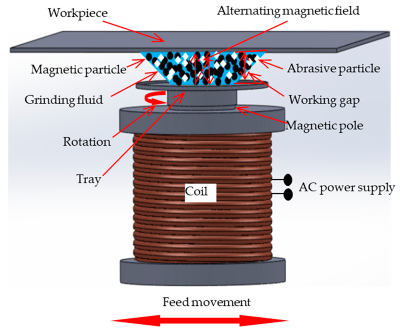
2.1. Processing Principle

Figure 1 shows the processing principle of the magnetic abrasive finishing process using an alternating magnetic field. Between the tray and the workpiece is the composite magnetic finishing fluid composed of a mixture of grinding fluid, MPs, and APs. After supplying alternating current or direct current to the electromagnetic coil, an alternating magnetic field or static magnetic field is generated. In addition, the motor is used to achieve magnetic pole rotation and feed movement. This leads to relative friction between the surface of the workpiece and the magnetic cluster, thereby effectively achieving MR. The periodic change of the alternating current causes the magnetic cluster to fluctuate up and down. This allows the magnetic cluster to recover its shape after it contacts the workpiece, and it can also update the APs in contact with the workpiece. This ensures the stability of the grinding tool and improves finishing efficiency.

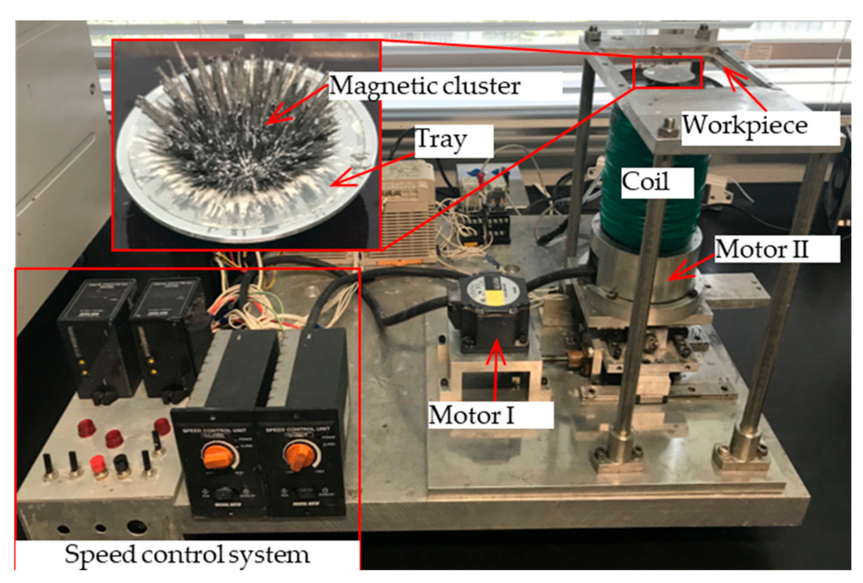
2.2. Experimental Setup

Figure 2 shows a photo of the experimental device. The electromagnetic coil can be supplied to the current through an AC power supply device according to experimental requirements. The tray is connected to the magnetic pole. The rotational movement of the magnetic pole is driven by the motor II. The workpiece is placed on the table above the tray. The composite magnetic finishing fluid on the tray forms magnetic cluster and can finish the bottom surface of the workpiece. The electromagnetic coil is connected to the mobile station and can be driven by the motor I to achieve reciprocating motion.
In addition, the magnetic flux density was measured in the experiment. The schematic diagram of the measurement principle is shown in Figure 3. The magnetic flux density above the axis of the magnetic pole is measured using a gauss meter (GM-4002) and probe (T-401) produced by EMIC (Tokyo, Japan). When measuring, the sensing area of the probe is placed above the magnetic pole axis. The magnetic flux density changes are recorded by a logger (midi LOGGER GL240 produced by Graphtec Corporation, Yokohama, Japan).

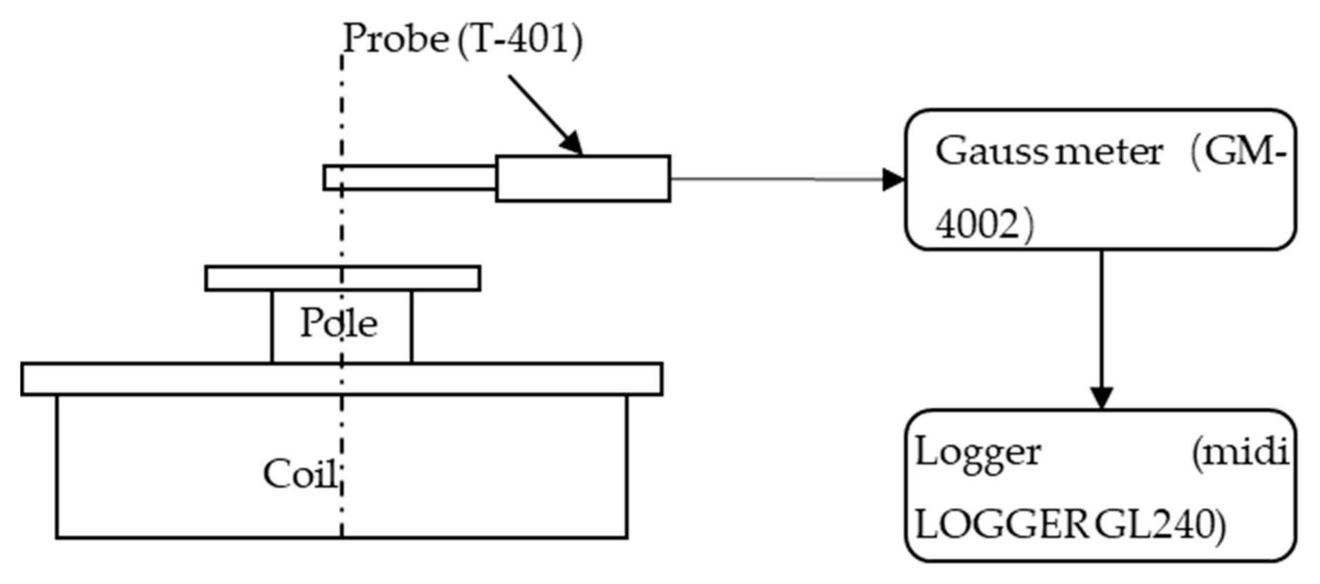
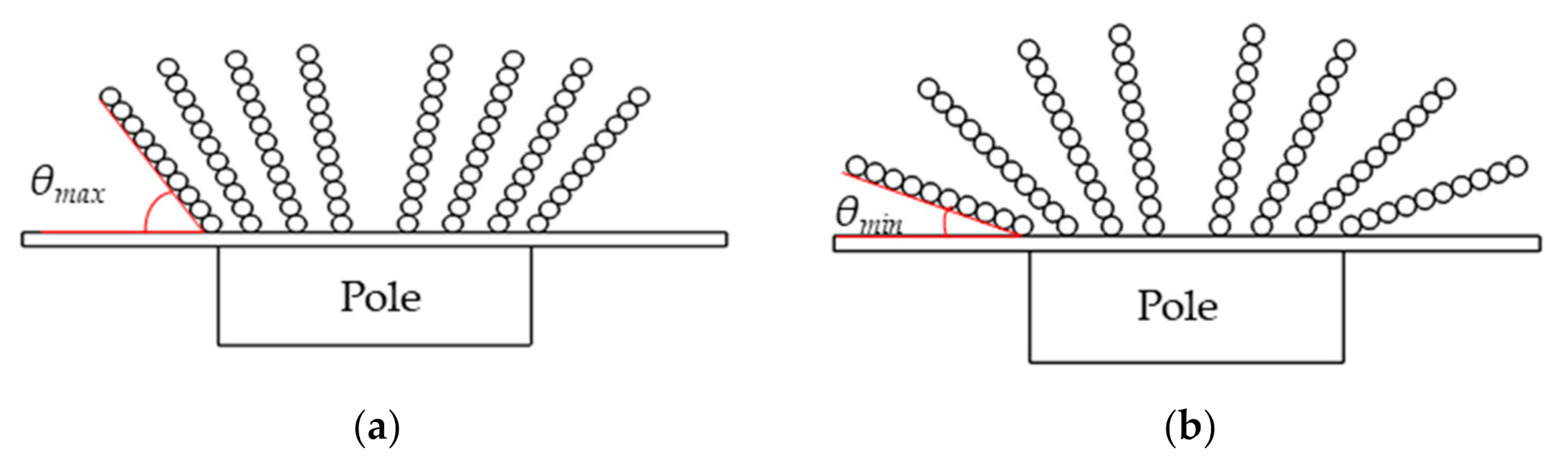
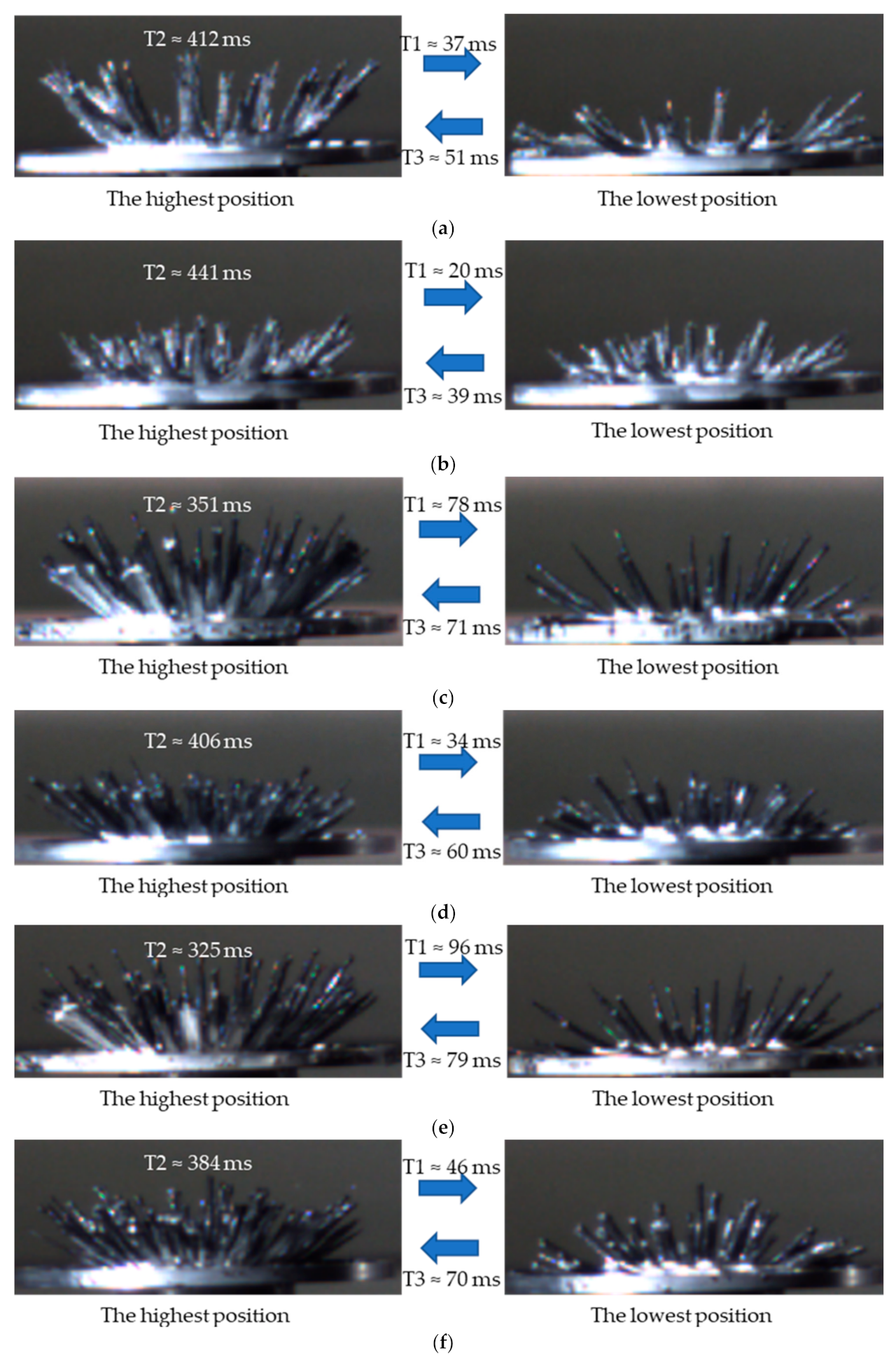
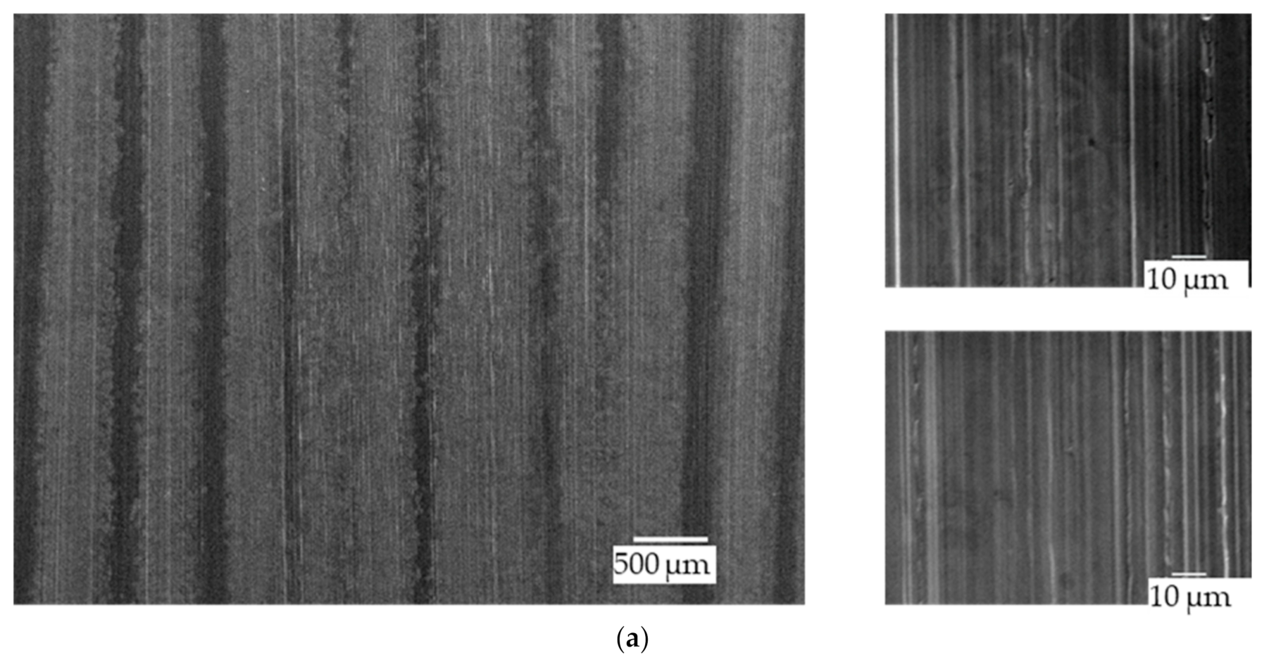
2.3. Magnetic Cluster Observation

Figure 4 is a schematic diagram of the magnetic cluster fluctuating in an alternating magnetic field. As the absolute value of the magnetic flux density increases, the angle between the magnetic cluster and the tray gradually increases from the minimum to the maximum. The subsequent increase in the absolute value of the magnetic flux density will not continue to cause the magnetic cluster to fluctuate upward, so the magnetic cluster will stay at the maximum angular position for a while. When the absolute value of the magnetic flux density decreases to a certain value, the magnetic cluster begins to fluctuate downwards until the minimum angle. In order to observe the difference of the magnetic cluster fluctuations in the two waveforms, a high-speed camera was used to observe the fluctuation process of the magnetic cluster. The shooting frequency of the high-speed camera is 1000 fps.
Figure 5 shows the photos of the lowest and highest positions of the magnetic cluster in the case of sinusoidal alternating current (Sin-AC) and square alternating current (S-AC). In the figure, T1 is the time for the magnetic cluster to drop from the highest position to the lowest position, T2 is the time for the magnetic cluster to stay at the highest position, and T3 is the time for the magnetic cluster to rise from the lowest position to the highest position. When the size of the MPs is the same, T2 is longer than in S-AC as compared to Sin-AC. As the size of the MPs increases, T2 increases when the current waveform is the same. At the same time, the difference in T2 of the two waveforms gradually decreases, with the increase in size of the MPs. When the magnetic cluster is in the highest position, it means that it will have a higher finishing efficiency than other positions.

3. Experimental Conditions and Method

The experimental conditions are shown in Table 1. SUS304 austenitic stainless-steel plates of size 100 × 100 × 1 mm are prepared as workpieces. The chemical composition and properties of SUS304 austenitic stainless-steel plate are shown in Table 2. The composite magnetic finishing fluid used in the experiment was obtained by uniformly mixing 1.2 g electrolytic iron powder, 0.3 g APs, and 0.8 mL oily grinding fluid. Because this experiment mainly investigates the influence of finishing parameters, and at the same time under optimized experimental conditions, the surface roughness is basically stable after 40 min. Therefore, the total finishing time is set to 40 min, and the workpiece is cleaned and measured every 10 min. The surface roughness of the workpiece is measured by the surface roughness meter (SURFPAK-SV produced by Mitutoyo Corporation, Kawasaki, Japan). The weight of the workpiece is measured using a semi-micro balance AEG-80SM (Shimadzu Corporation, Kyoto, Japan, minimum weighing unit: 0.01 mg). The amount of material removal is obtained by calculating the difference between the weight of the workpiece before and after finishing. In this experiment, three types of currents are used, which are Sin-AC, S-AC, and direct current (DC) as shown in Figure 6. The average value of the absolute value of the current under different waveforms is 1.9 A. The maximum and minimum current of S-AC is 1.9 A. The effects of three currents on finishing characteristics are compared. In addition, discuss the effects of MPs size, magnetic field frequency, APs size, and magnetic pole rotation speed on finishing characteristics when using S-AC.

4. Experimental Results and Discussion

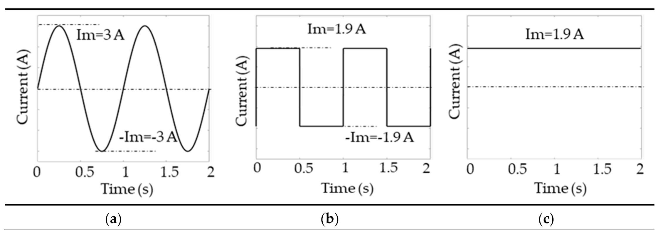
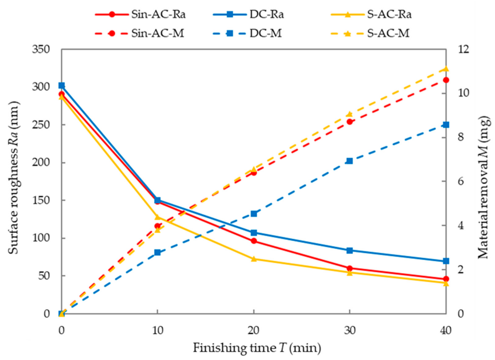
4.1. Current Waveform

The effect of the current waveform on surface roughness and MR is shown in Figure 7. It can be seen that the amount of MR is the least and the surface quality is the worst at DC. This is mainly because, in the case of Sin-AC and S-AC, the magnetic cluster constantly fluctuate with changes in current. This fluctuating motion can continuously update the APs in contact with the workpiece, thereby ensuring the stability of the finishing tool. Therefore, the finishing efficiency is higher than in DC. In the case of S-AC, the amount of MR is slightly higher than that of Sin-AC, and the surface roughness changes faster than Sin-AC. In order to analyze the reason, the change of magnetic flux density was measured.
Figure 8 shows the change curve of the magnetic flux density above the magnetic pole axis with time. The red curve is used as the reference curve, which is the standard waveform curve drawn under the same conditions (such as frequency, maximum value, etc.). It can be seen that the change of the measurement curve lags behind the reference curve, which is mainly affected by the magnetization characteristics of the material. Compared with the reference curve, it can be found that the magnetic flux density is weakened during magnetization, and the magnetic flux density is enhanced during demagnetization. In addition, it can be seen that the maximum magnetic flux density is greater than S-AC in the case of Sin-AC. But calculating the average value of the absolute value of the magnetic flux density (Ba) in one cycle, it is found that the Ba values of Sin-AC and S-AC are only slightly different, which are 120.67 mT and 120.31 mT, respectively. The finishing force is mainly affected by the size of MPs and the strength of the magnetic field. Therefore, in the case of the two waveforms, the average finishing force should be close. According to previous observations of the magnetic cluster, it can be found that the hold time (T2) of the magnetic cluster at the highest position is longer in the case of S-AC. Therefore, higher finishing efficiency is obtained in the case of S-AC.

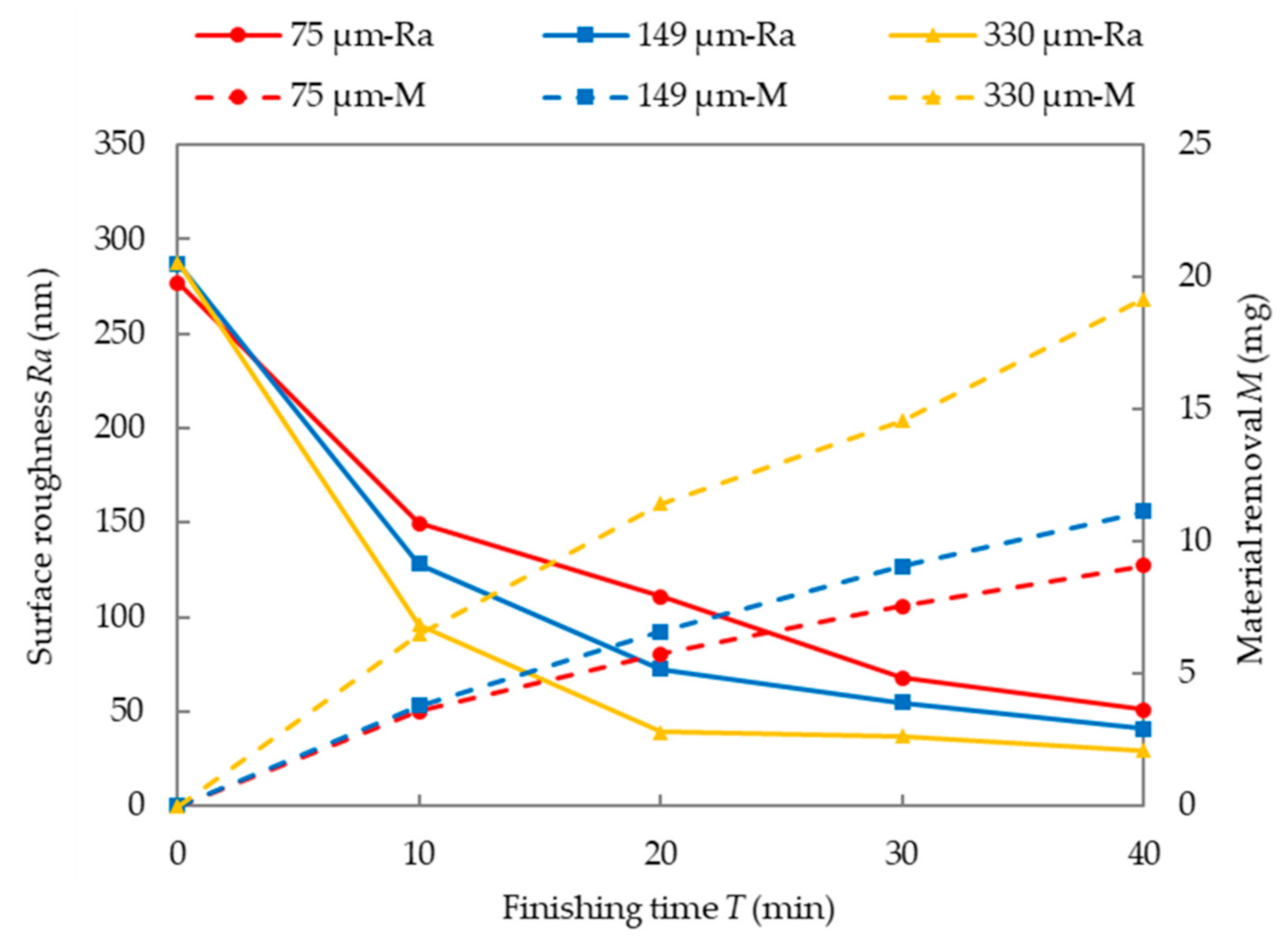
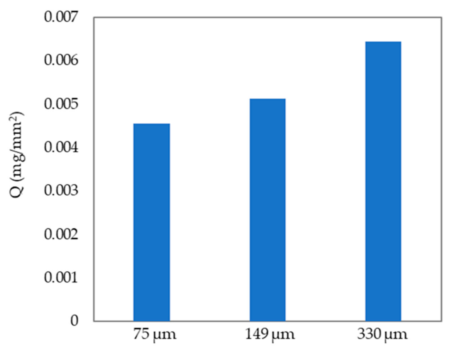
4.2. Magnetic particle size
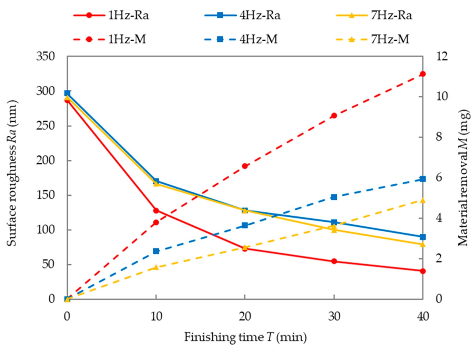
Figure 9 shows the effect of the MPs size on surface roughness and MR. According to the observation of the workpiece surface, the finishing area increases as the size of MPs increases, as shown in Figure 10. In the figure, L is the length of the finishing area and D is the rotating diameter of the magnetic cluster. It can be seen that as the size of APs increases, D gradually increases. This is because the magnetic force between MPs increases as the particle size increases [28]. Therefore, the magnetic cluster that can be formed is longer, and the finishing area increases. In order to accurately evaluate the MR, the MR per unit area (Q, mg/mm2) is calculated.
Q   =   MR / S ,
where MR (mg) is the total amount of MR, and S (mm2) is the area of the finishing area. The finishing area S is calculated by the following equation,
S   =   L D × D + π ( D / 2 ) 2 ,
The Q at different particle sizes is shown in Figure 11. According to Figure 9 and Figure 11, it can be seen that as the size of MPs increases, Q increases, and the surface roughness changes faster. This is mainly because the increase in the size of the MPs will increase the finishing force, thereby increasing the finishing efficiency [26].

4.3. Frequency

Figure 12 shows the effect of current frequency on surface roughness and MR. It can be seen that as the frequency of the current increases, the amount of MR decreases significantly. The surface quality is best obtained at 1 Hz. According to the comparison between the measured value and the reference curve in Figure 8, it can be seen that the magnetic flux density is relatively weakened during the magnetization process and relatively enhanced during the demagnetization process. But in the case of S-AC, the degree of weakening is significantly greater than the degree of enhancement. Therefore, as the frequency of the current increases, the degree to which the magnetic flux density is weakened increases. In turn, the finishing efficiency is reduced.

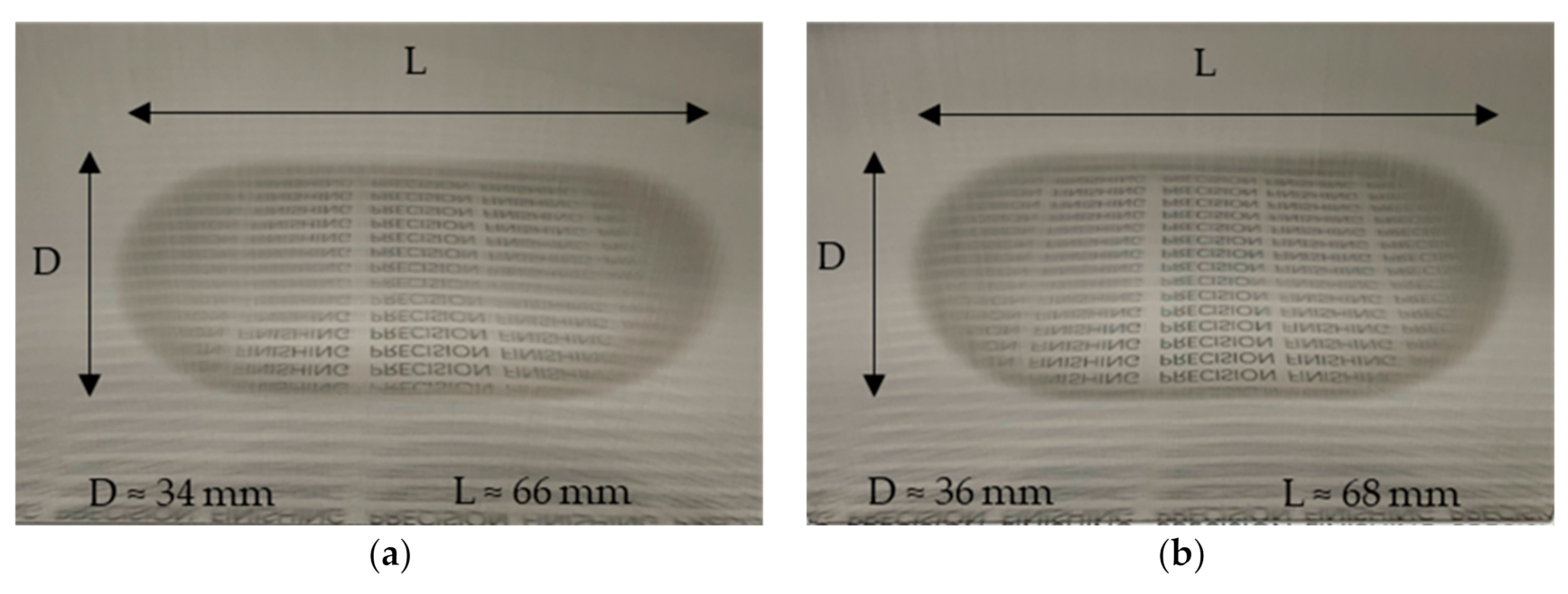
4.4. Abrasive Particle Size

Figure 13 shows the effect of APs size on surface roughness and MR. It can be seen that the highest MR and the best surface quality are obtained when using WA#8000 APs. In addition, at 10 min, the MR and surface quality changes of WA#20000 are close to WA#8000. But in the next 30 min, the change rate of surface roughness and MR gradually slows down. In order to explore the reason, the initial workpiece surface and APs were observed, as shown in Figure 14. It can be seen from Figure 14a that the initial surface of the workpiece has large grooves and is also full of small grooves. Figure 14b shows that there are significantly more small particles at WA#20000.
Furthermore, a white light interferometer (Zygo NewView7000 produced by Zygo Corporation, Middlefield, CT, U.S.) was used to observe the surface of the workpiece after finishing, as shown in Figure 15. As can be seen in Figure 15a, there is no obvious abrasive sliding trace at WA#6000. According to Jain et al. [29], a single AP cutting material needs to meet the following relationship,
Fc A s τ ,
where Fc is the tangential force acting on AP, A s is the projected area of penetration, and τ is the shear strength of the workpiece material.
At WA#6000, due to the increase of A s the tangential force required to complete the cut material increases. According to the surface state shown in Figure 15a, it can be inferred that because there is not enough tangential force acting on the APs, the APs does not slip but rolls on the surface of the workpiece. Therefore, the finishing efficiency is low.
At WA#8000 and WA#20000, obvious finishing traces can be seen. According to Figure 14 and Figure 15, in the first 10 min, the peak tip of the workpiece surface will be preferentially removed. During this process, APs enter the gap between the two peaks to cut the peak tip, which mainly depends on the tangential force. In the next 30 min, as small peaks on the surface are gradually removed, material removal in a relatively flat area mainly depends on APs being pressed into the workpiece. During this process, the material removal amount of a single AP mainly depends on the sliding distance and the projected area of the pressed workpiece, which is not only related to the tangential force but also to the normal force. When other conditions are the same, the total normal force is not much different. When the weights of APs are the same, the number of APs is more at WA#20000. The increase in the number of APs disperses the normal force, which reduces the normal force acting on a single AP, thereby reducing the penetration depth. As shown in Figure 15b,c as the size of the APs increases, the depth of the finishing mark also increases. Therefore, when the sliding distance is the same, the MR of a single AP increases. This leads to a decrease in the MR of WA#20000 in the following 30 min.

4.5. Rotational Speed

Figure 16 shows the effect of magnetic pole rotation speed on surface roughness and MR. It can be seen that as the rotation speed increases, the finishing efficiency increases. In the abrasive micromachining process, the material removal rate (MRR) can be given by the following equation [30]:
M R R = C P × P × V × ρ
where P is the normal finishing force acting on the abrasive particle, V is the relative speed between the abrasive particle and the workpiece, ρ is the material density of the workpiece, and Cp is a constant. The increase of the magnetic pole rotation speed increases the relative speed between the APs and the workpiece, so the finishing efficiency is higher.
Figure 17 is the 3D photographs of the workpiece surface before and after finishing. It can be seen that the small grooves on the surface after finishing at the three rotational speeds are almost completely removed, but some large grooves are still not removed at 350 rpm and 450 rpm. The best surface quality is obtained when the magnetic pole rotation speed is 550 rpm.

5. Conclusions

This article investigates the influence of the AC waveform on the finishing characteristics. The behavior characteristics of the magnetic cluster were observed and analyzed. The main conclusions are as follows.
  • When using a square wave, a higher magnetic cluster fluctuation speed can be obtained, and as the size of the MPs decreases, the difference between the magnetic cluster fluctuation speed of the two waveforms is greater.
  • Under this experimental condition, when the current waveform is a square wave, the finishing efficiency is improved.
  • When the waveform of the alternating current is a square wave, as the size of the MPs increases and the frequency of the magnetic field decreases, the finishing efficiency increases. At the same time, when the APs are WA#8000, the finishing efficiency is higher. In addition, the increase in the rotation speed of the magnetic pole significantly improves the finishing efficiency.
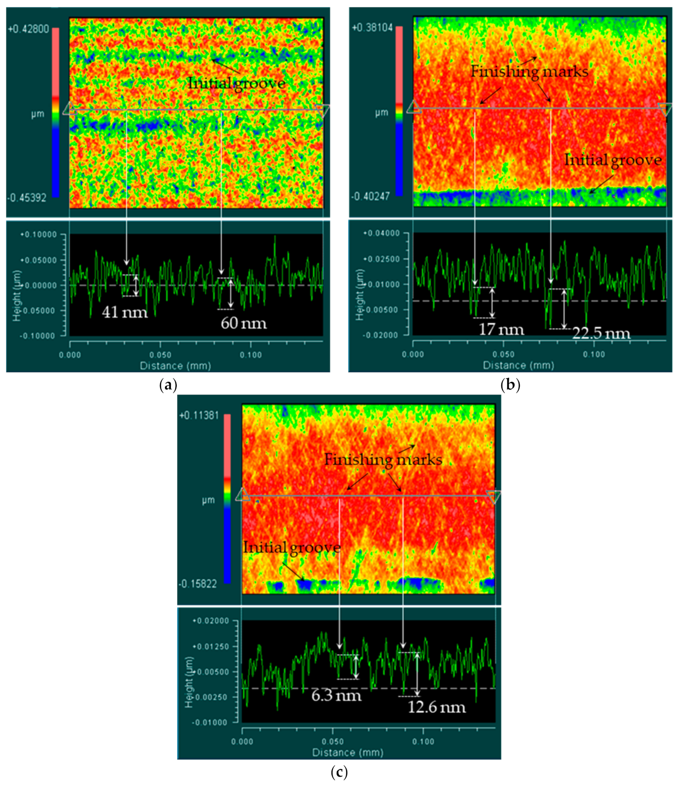
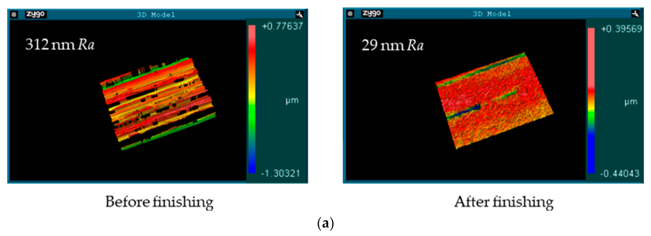
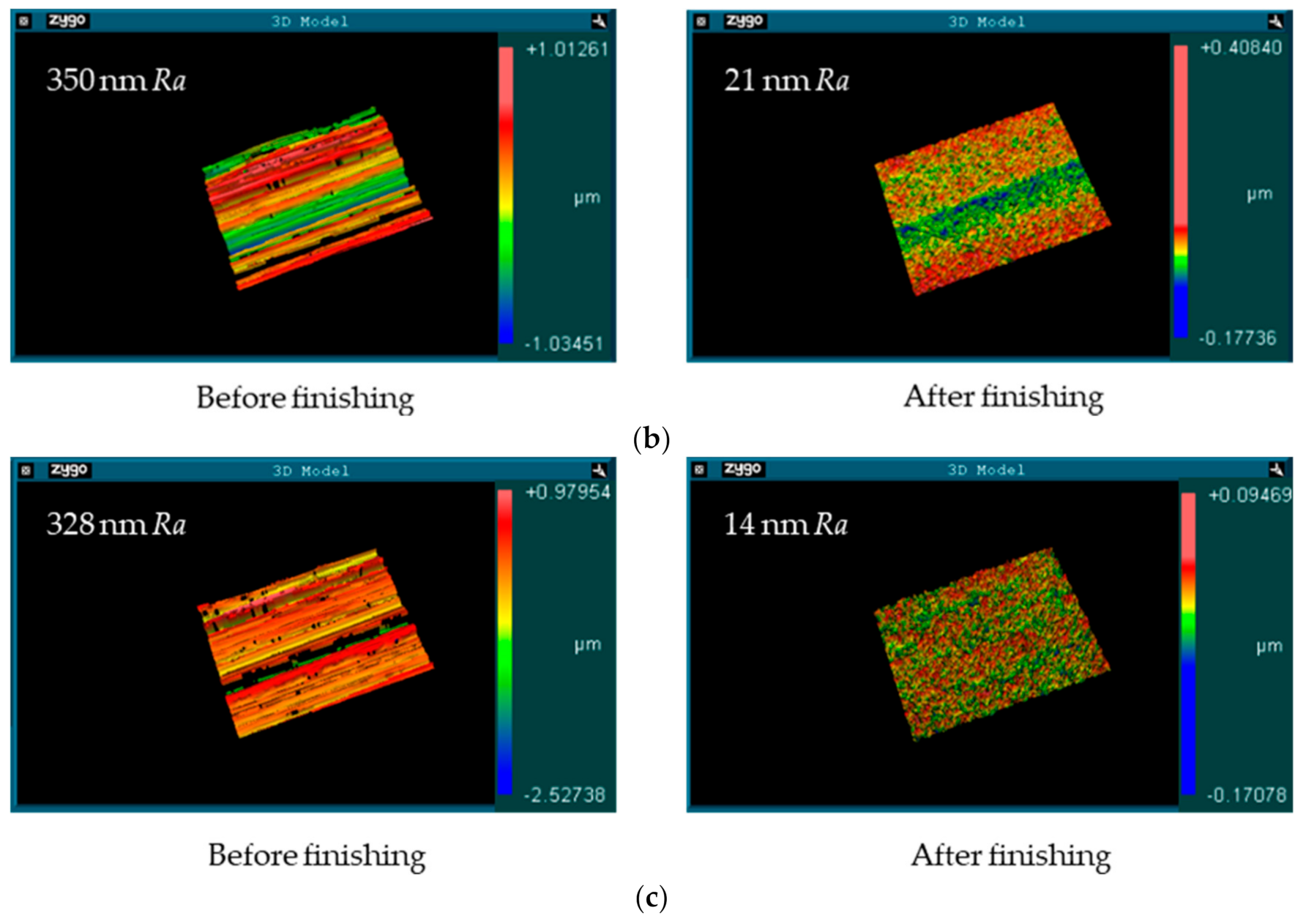
  • According to the experimental results, when the current waveform is a square wave, the average diameter of MPs is 149 μm, the current frequency is 1 Hz, the APs are WA#8000, and the rotation speed is 550 rpm, the surface roughness of the SUS304 stainless steel plate is improved from 328 nm Ra to 14 nm Ra within 40 min.

Author Contributions

Conceptualization, Y.Z.; methodology, H.X. and Y.Z.; investigation, H.X. and Y.Z.; resources, Y.Z.; data curation, H.X. and Y.Z.; writing—original draft preparation, H.X. and Y.Z.; writing—review and editing, Y.Z. and H.X.; supervision, Y.Z.; project administration, Y.Z. All authors have read and agreed to the published version of the manuscript.

Funding

This research received no external funding.

Conflicts of Interest

The authors declare no conflict of interest.

References

  1. Konefal, K.; Korzynski, M.; Byczkowska, Z.; Korzynska, K. Improved corrosion resistance of stainless steel X6CrNiMoTi17-12-2 by slide diamond burnishing. J. Mater. Process. Technol. 2013, 213, 1997–2004. [Google Scholar] [CrossRef]
  2. Bagehorn, S.; Wehr, J.; Maier, H.J. Application of mechanical surface finishing processes for roughness reduction and fatigue improvement of additively manufactured Ti-6Al-4V parts. Int. J. Fatigue 2017, 102, 135–142. [Google Scholar] [CrossRef]
  3. Jain, N.K.; Jain, V.K.; Jha, S. Parametric optimization of advanced fine-finishing processes. Int. J. Adv. Manuf. Technol. 2007, 34, 1191–1213. [Google Scholar] [CrossRef]
  4. Khalaj Amineh, S.; Fadaei Tehrani, A.; Mohammadi, A. Improving the surface quality in wire electrical discharge machined specimens by removing the recast layer using magnetic abrasive finishing method. Int. J. Adv. Manuf. Technol. 2013, 66, 1793–1803. [Google Scholar] [CrossRef]
  5. Uddin, M.S.; Santos, V.; Marian, R. Interplay of Process Variables in Magnetic Abrasive Finishing of AISI 1018 Steel Using SiC and Al2O3 Abrasives. J. Manuf. Mater. Process. 2019, 3, 29. [Google Scholar] [CrossRef] [Green Version]
  6. Wang, R.; Lim, P.; Heng, L.; Mun, S.D. Magnetic Abrasive Machining of Difficult-to-Cut Materials for Ultra-High-Speed Machining of AISI 304 Bars. Materials 2017, 10, 1029. [Google Scholar] [CrossRef] [Green Version]
  7. Zou, Y.; Shinmura, T.; Wang, F. Study on a Magnetic deburring method by the application of the plane magnetic abrasive machining process. Adv. Mater. Res. 2009, 76–78, 276–281. [Google Scholar] [CrossRef]
  8. Lin, C.; Yang, L.; Chow, H. Study of magnetic abrasive finishing in free-form surface operations using the Taguchi method. Int. J. Adv. Manuf. Technol. 2007, 34, 122–130. [Google Scholar] [CrossRef]
  9. Wang, Y.; Wu, Y.; Nomura, M. A novel magnetic field-assisted polishing method using magnetic compound slurry and its performance in mirror surface finishing of miniature V-grooves. AIP Adv. 2016, 6, 056602. [Google Scholar] [CrossRef] [Green Version]
  10. Shinmura, T.; Takazawa, K.; Hatano, E.; Aizawa, T. Study on magnetic abrasive process (finishing characteristics). Bull. Jpn. Soc. Precis. Eng. 1984, 18, 347–348. [Google Scholar]
  11. Shinmura, T.; Takazawa, K.; Hatano, E.; Aizawa, T. Study on magnetic abrasive process (Process principles and finishing possibility). Bull. Jpn. Soc. Precis. Eng. 1985, 19, 54–55. [Google Scholar]
  12. Zou, Y.; Xie, H.; Zhang, Y. Study on surface quality improvement of the plane magnetic abrasive finishing process. Int. J. Adv. Manuf. Technol. 2020, 109, 1825–1839. [Google Scholar] [CrossRef]
  13. Jiao, A.; Quan, H.; Li, Z.; Zou, Y. Study on improving the trajectory to elevate the surface quality of plane magnetic abrasive finishing. Int. J. Adv. Manuf. Technol. 2015, 80, 1613–1623. [Google Scholar] [CrossRef]
  14. Zou, Y.; Xing, B.; Sun, X. Study on the magnetic abrasive finishing combined with electrolytic process—Investigation of machining mechanism. Int. J. Adv. Manuf. Technol. 2020, 108, 1675–1689. [Google Scholar] [CrossRef]
  15. Sun, X.; Zou, Y. Study on Electrolytic Magnetic Abrasive Finishing for Finishing Stainless Steel SUS304 Plane with a Special Compound Machining Tool. J. Manuf. Mater. Process. 2018, 2, 41. [Google Scholar] [CrossRef] [Green Version]
  16. Yin, S.; Shinmura, T. Vertical vibration-assisted magnetic abrasive finishing and deburring for magnesium alloy. Int. J. Mach. Tool. Manuf. 2004, 44, 1297–1303. [Google Scholar] [CrossRef]
  17. Yin, S.; Shinmura, T. A comparative study: Polishing characteristics and its mechanisms of three vibration modes in vibration-assisted magnetic abrasive polishing. Int. J. Mach. Tool. Manuf. 2004, 44, 383–390. [Google Scholar] [CrossRef]
  18. Jain, V.K.; Kumar, P.; Behera, P.K.; Jayswal, S.C. Effect of working gap and circumferential speed on the performance of magnetic abrasive finishing process. Wear 2001, 250, 384–390. [Google Scholar] [CrossRef]
  19. Yamaguchi, H.; Shinmura, T.; Kobayashi, A. Development of an internal magnetic abrasive finishing process for nonmagnetic complex shaped tubes. JSME Int. J. Ser. C 2001, 44, 275–281. [Google Scholar] [CrossRef] [Green Version]
  20. Yamaguchi, H.; Shinmura, T. Internal finishing process for alumina ceramic components by a magnetic field assisted finishing process. Precis. Eng. 2004, 28, 135–142. [Google Scholar] [CrossRef]
  21. Kala, P.; Pandey, P.M.; Verma, G.C.; Sharma, V. Understanding flexible abrasive brush behavior for double disk magnetic abrasive finishing based on force signature. J. Manuf. Process 2017, 28, 442–448. [Google Scholar] [CrossRef]
  22. Mulik, R.S.; Pandey, P.M. Experimental Investigations and Modeling of Finishing Force and Torque in Ultrasonic Assisted Magnetic Abrasive Finishing. ASME J. Manuf. Sci. Eng. 2012, 134, 051008. [Google Scholar] [CrossRef]
  23. Lee, Y.H.; Wu, K.L.; Jhou, J.H.; Tsai, Y.H.; Yan, B.H. Two-dimensional vibration-assisted magnetic abrasive finishing of stainless steel SUS304. Int. J. Adv. Manuf. Technol. 2013, 69, 2723–2733. [Google Scholar] [CrossRef]
  24. Lee, Y.H.; Wu, K.L.; Bai, C.T.; Liao, C.Y.; Yan, B.H. Planetary motion combined with two-dimensional vibration-assisted magnetic abrasive finishing. Int. J. Adv. Manuf. Technol. 2015, 76, 1865–1877. [Google Scholar] [CrossRef]
  25. Wu, J.; Zou, Y.; Sugiyama, H. Study on ultra-precision magnetic abrasive finishing process using low frequency alternating magnetic field. J. Magn. Magn. Mater. 2015, 386, 50–59. [Google Scholar] [CrossRef]
  26. Zou, Y.; Xie, H.; Dong, C.; Wu, J. Study on complex micro surface finishing of alumina ceramic by the magnetic abrasive finishing process using alternating magnetic field. Int. J. Adv. Manuf. Technol. 2018, 97, 2193–2202. [Google Scholar] [CrossRef]
  27. Xie, H.; Zou, Y.; Dong, C.; Wu, J. Study on the magnetic abrasive finishing process using alternating magnetic field: Investigation of mechanism and applied to aluminum alloy plate. Int. J. Adv. Manuf. Technol. 2019, 102, 1509–1520. [Google Scholar] [CrossRef]
  28. Shinmura, T.; Aizawa, T. Study on internal finishing of non-ferromagnetic tubing by magnetic abrasive machining process. Bull. Jpn. Soc. Precis. Eng. 1989, 23, 37–41. [Google Scholar]
  29. Jain, V.K. Magnetic field assisted abrasive based micro-/nano-finishing. J. Mater. Process. Technol. 2009, 209, 6022–6038. [Google Scholar] [CrossRef]
  30. Cheng, K. Abrasive micromachining and microgrinding. In Micromachining of Engineering Material; McGeough, J., Ed.; CRC Press Dekker: New York, NY, USA, 2002; pp. 85–123. [Google Scholar]
Figure 1. Schematic of processing principle.
Machines 08 00075 g001
Figure 2. External view of the experimental setup.
Machines 08 00075 g002
Figure 3. Magnetic flux density measurement.
Machines 08 00075 g003
Figure 4. Schematic diagram of magnetic cluster fluctuation. (a) The highest position; (b) The lowest position.
Machines 08 00075 g004
Figure 5. The lowest position and the highest position in the fluctuation period of the magnetic cluster. (a) Sin-AC, 330 μm; (b) S-AC, 330 μm; (c) Sin-AC, 149 μm; (d) S-AC, 149 μm; (e) Sin-AC, 75 μm; (f) S-AC, 75 μm.
Machines 08 00075 g005
Figure 6. Current waveform diagram. (a) sin-AC, 1Hz; (b) S-AC, 1Hz; (c) DC.
Machines 08 00075 g006
Figure 7. The effect of current waveform on surface roughness and material removal. (Magnetic particles: 149 μm, frequency: 1 Hz, abrasive particles: WA#8000, rotational speed: 350 rpm).
Machines 08 00075 g007
Figure 8. The change curve of magnetic flux density with time. (a) Sin-AC; (b) S-AC.
Machines 08 00075 g008
Figure 9. The effect of magnetic particles size on surface roughness and material removal. (Current waveform: S-AC, frequency: 1 Hz, abrasive particles: WA#8000, rotational speed: 350 rpm).
Machines 08 00075 g009
Figure 10. Photos of the workpieces. (a) Magnetic particles: 75 μm; (b) Magnetic particles: 149 μm; (c) Magnetic particles: 330 μm.
Machines 08 00075 g010aMachines 08 00075 g010b
Figure 11. The amount of material removal per unit area (Q).
Machines 08 00075 g011
Figure 12. The effect of current frequency on surface roughness and material removal. (Magnetic particles: 149 μm, current waveform: S-AC, abrasive particles: WA#8000, rotational speed: 350 rpm).
Machines 08 00075 g012
Figure 13. The effect of abrasive particles size on surface roughness and material removal. (Magnetic particles: 149 μm, current waveform: S-AC, frequency: 1 Hz, rotational speed: 350 rpm).
Machines 08 00075 g013
Figure 14. SEM images of the workpiece surface and abrasive particles. (a) Workpiece surface; (b) Abrasive particles.
Machines 08 00075 g014aMachines 08 00075 g014b
Figure 15. The Photographs of the workpiece surface after finishing (White Light Interferometers). (a) WA#6000; (b) WA#8000; (c) WA#20000.
Machines 08 00075 g015
Figure 16. The effect of rotational speed on surface roughness and material removal. (Magnetic particles: 149 μm, current waveform: S-AC, frequency: 1 Hz, abrasive particles: WA#8000).
Machines 08 00075 g016
Figure 17. 3D photographs of the workpiece surface before and after finishing. (a) 350 rpm; (b) 450 rpm; (c) 550 rpm.
Machines 08 00075 g017aMachines 08 00075 g017b
Table 1. Experimental conditions.
WorkpieceSUS304 Austenitic Stainless Steel Plate with the Size of 100 mm × 100 mm × 1 mm
Grinding fluidOily grinding fluid (Honilo 988): 0.8 mL
Working gap1.5 mm
Feed speed260 mm/min
Current1.9 A (Average)
Finishing timeSingle 10 min (40 min)
Magnetic particlesElectrolytic iron powder, 75 μm in mean dia:1.2 g
Electrolytic iron powder, 149 μm in mean dia:1.2 g
Electrolytic iron powder, 330 μm in mean dia:1.2 g
Current waveformDC, Sine (Sin-AC), Square (S-AC)
Current frequency1 Hz, 4 Hz, 7 Hz
Abrasive particlesWA#6000: 0.3 g, WA#8000: 0.3 g, WA#20000: 0.3 g
Rotational speed350 rpm, 450 rpm, 550 rpm
Table 2. The chemical composition and properties of SUS304 austenitic stainless steel plate.
Chemical Composition (%)CCrNiMnSiPS
≤0.0818.00–20.008.00–10.50≤2.00≤1.00≤0.045≤0.030
Hardness test (max)HB 187, HRB 90, HV 200
Proof stress (N/mm2)205
Tensile strength (N/mm2)520
Elongation (%)40
Publisher’s Note: MDPI stays neutral with regard to jurisdictional claims in published maps and institutional affiliations.

