Article

Investigation of Finishing Aluminum Alloy A5052 Using the Magnetic Abrasive Finishing Combined with Electrolytic Process

Graduate School of Engineering, Utsunomiya University, 7-1-2 Yoto, Utsunomiya Tochigi 321-8585, Japan
*
Author to whom correspondence should be addressed.
Machines 2020, 8(4), 78; https://doi.org/10.3390/machines8040078
Submission received: 14 October 2020 / Revised: 10 November 2020 / Accepted: 17 November 2020 / Published: 19 November 2020
(This article belongs to the Special Issue Advanced Autonomous Machines and Designs)

Abstract

:
The magnetic abrasive finishing combined with electrolytic (EMAF) process was proposed to improve the finishing efficiency of the traditional magnetic abrasive finishing (MAF) process. Since the EMAF process contains electrolysis reactions, the machining mechanism of processing different metal is different. In this paper, a series of experiments were conducted to explore the feasibility of using the compound processing tool to finish aluminum alloy A5052, and to preliminary explore the machining mechanism. Surface roughness and material removal are used to evaluate the finishing effect and the finishing efficiency, respectively. The EMAF processing current curve is used to evaluate and analyze the EMAF process. The feasibility of the EMAF processing is proved by the analysis of simulations and the experimental results. Finally, through a series of exploration experiments and parameter optimization experiments, the main conclusions are as follows: (1) Compared with the traditional MAF process, when finishing the surface of aluminum alloy A5052 by the same compound processing tool and at the same experimental conditions (except the electrolysis conditions), the EMAF process, which includes electrolysis reactions, can achieve higher finishing efficiency. (2) In this study, when the working gap is 1 mm and the concentration of NaNO3 solution is 15%, the recommended processing voltage is about 3.4 V.

1. Introduction

As a kind of non-traditional precision finishing technology, the magnetic abrasive finishing (MAF) process has been widely used in aerospace, optics, semiconductors, biological engineering, etc. [1,2,3,4,5]. Because the magnetic field has a penetrating effect, it can penetrate the outer layer of the workpiece and form magnetic brush inside of it [6]. Therefore, MAF process can be used to process fine workpieces that are difficult to enter and finish by traditional machining tools [7]. Magnetic brush is flexible and can adapt to the surface of parts with complex shapes, and the MAF process is usually used to finish fine curved surfaces and inner surfaces of tubes [3,4,5]. The MAF process has many advantages, it can realize the high-quality surface finishing of the workpiece, but the problem is that the finishing efficiency is not high enough. In order to improve the finishing efficiency of the MAF process, the magnetic abrasive finishing combined with electrolytic process (EMAF) was proposed [8].
The electrolysis reactions use the principle of anode electrochemical dissolution to achieve material removal, the processing efficiency is high and has nothing to do with the hardness and toughness of the material [9,10]. The electrolysis reactions in EMAF process can flatten the surface of the workpiece through anodic dissolution. Meanwhile, the passive films are removed by magnetic brush to achieve efficient precision machining [11]. During the EMAF processing, the processing tool (electrode) does not come into direct contact with the workpiece, so the tool electrode does not dissolve and has a long service life [12,13].
The workpiece material aluminum alloy A5052 in this experiment belongs to aluminum alloy 5000 series which has magnesium (2.2–2.8%) as the major alloying element, and it has the advantages of light weight, good workability, high thermal conductivity, corrosion resistance to seawater and salt spray, etc. Aluminum and its alloys are widely used automotive, aerospace, marine engineering, etc., due to their superior physical and chemical properties [14,15,16]. Therefore, exploring the feasibility and machining mechanism of finishing aluminum alloy materials has great significance to the future exploration of using EMAF process for precision finishing fine surfaces. This study aims to explore the possibility of EMAF processing aluminum alloy A5052 by the compound processing tool. The experimental results are analyzed in combination with the simulation to verify the rationality of the arrangement of magnetic poles and electrode. Through comparison and analysis of the experimental results, the feasibility of using the compound processing tool to finish aluminum alloy A5052 is proved, and the machining mechanism is initially explored.

2. Processing Principle

In this section, the EMAF processing principle is first introduced, and then the effect of the electrolysis reactions in the EMAF process and the MAF process are introduced, respectively.

2.1. Principle of EMAF Process

The EMAF processing principle is shown in Figure 1. The workpiece and the electrode of compound processing tool are, respectively, connected to the positive and negative poles of the DC power supply. The compound processing tool consists of a cross electrode and four magnetic poles (arranged in the same direction). During the EMAF processing, both the workpiece and the electrode surface are immersed in the electrolyte. The workpiece surface is finished by the rotation of the compound processing tool and the horizontal feed movement of the X-Y stage. The current and voltage values during EMAF processing are recorded by a data logger, and the current and voltage curves are used for the analysis of experimental results.
The electrolysis reactions and the MAF processing act on the workpiece surface at the same time because the electrode and the magnetic poles rotate together. The electrolysis reactions are used to efficiently remove the surface protrusions, and the MAF process is used to further refine the surface of the workpiece. The processing efficiency of the EMAF process is higher than the traditional MAF process due to the electrolysis reactions is very efficient and is not affected by the hardness of the material. The MAF process included in EMAF process is also used to remove the passive film produced by electrolysis reactions on the surface. The characteristics of EMAF process not only retains the high efficiency of the electrolysis reaction, but also retains the high precision of the MAF process.
During the EMAF processing, the material removal of electrolysis reactions is shown by the Formula (1). In the formula, m is the amount of material removal, η is the current efficiency coefficient, I is the current value (A), t is the energization time (s), A is the atomic weight, F is the faraday constant (96500C) and n is the valence of the electrolysis product [17,18].
m = η I t A F n ( g ) ,

2.2. Principle of Electrolysis Reactions in EMAF Process

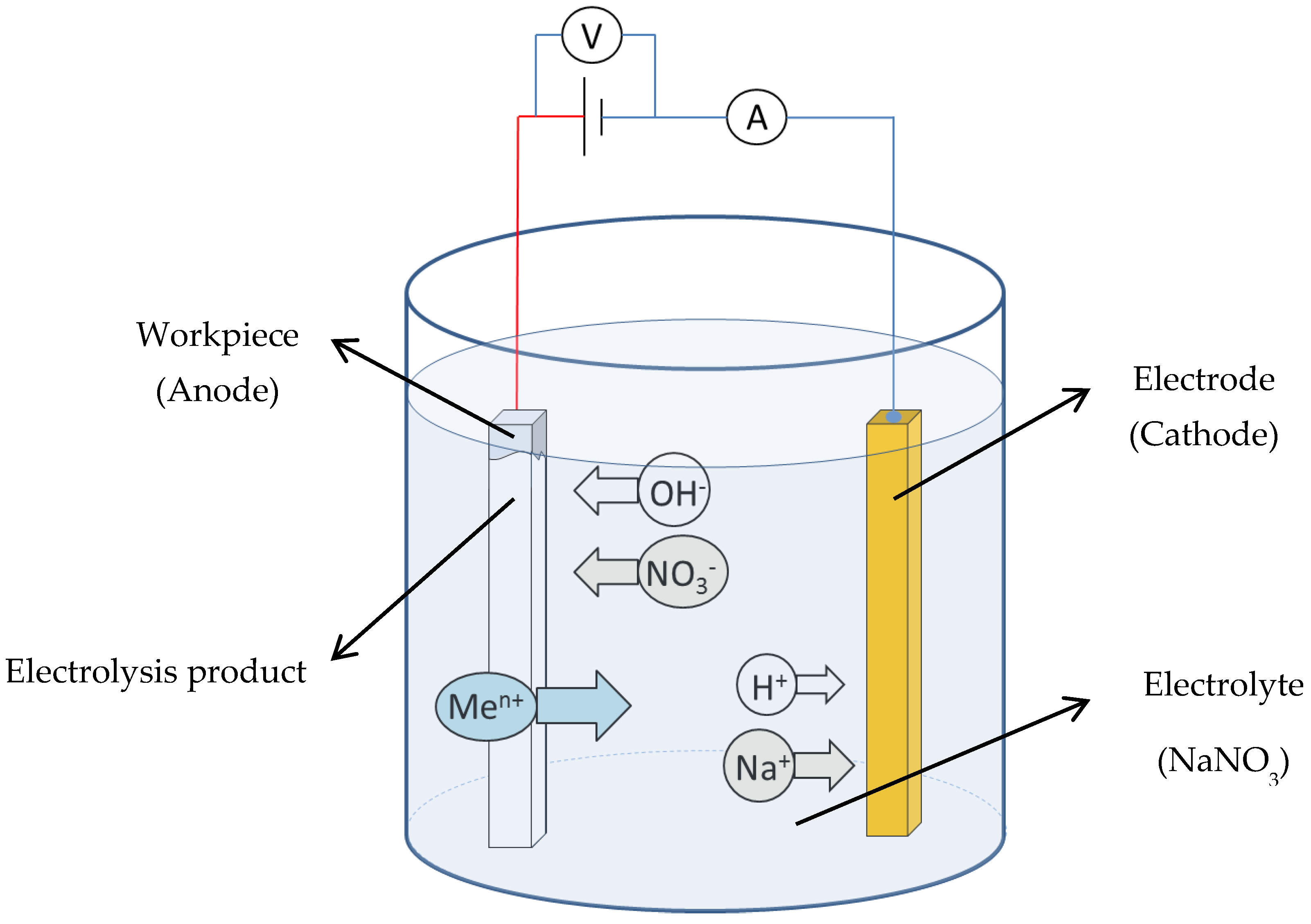
The schematic of electrolysis reactions in the EMAF process is shown in Figure 2. In this study, neutral sodium nitrate aqueous solution is selected as the electrolyte. The main electrolysis reactions that occur during the EMAF process when the power is turned on are shown in Formulas (2) and (3), [19].
The main electrolysis reaction that occurs on the surface of cathode:
2H+ + 2e → H2↑,
Metal dissolution reaction of workpiece (anode):
Me → Men+ + ne,

2.3. Principle of Plane MAF Process

During the MAF processing, the magnetic brush formed between the bottom surface of the magnetic pole and the surface of workpiece is used as a processing tool to finish workpiece. The magnetic force F experienced by a single iron powder in magnetic field can be decomposed into a force Fx (along the direction of the magnetic force) and Fy (along the direction of magnetic equipotential line), as shown in Formulas (4) and (5) [20,21].
F x = V χ μ 0 H ( H / x ) ,
F y = V χ μ 0 H ( H / y ) ,
where V is the volume of magnetic particles, χ is the magnetic susceptibility of magnetic particles, μ0 is vacuum permeability, H is the magnetic field intensity and ∂H/∂x and ∂H/∂y are the gradient of magnetic field intensity in x and y directions, respectively.

3. Experimental Setup and Compound Processing Tool

3.1. EMAF Processing Setup

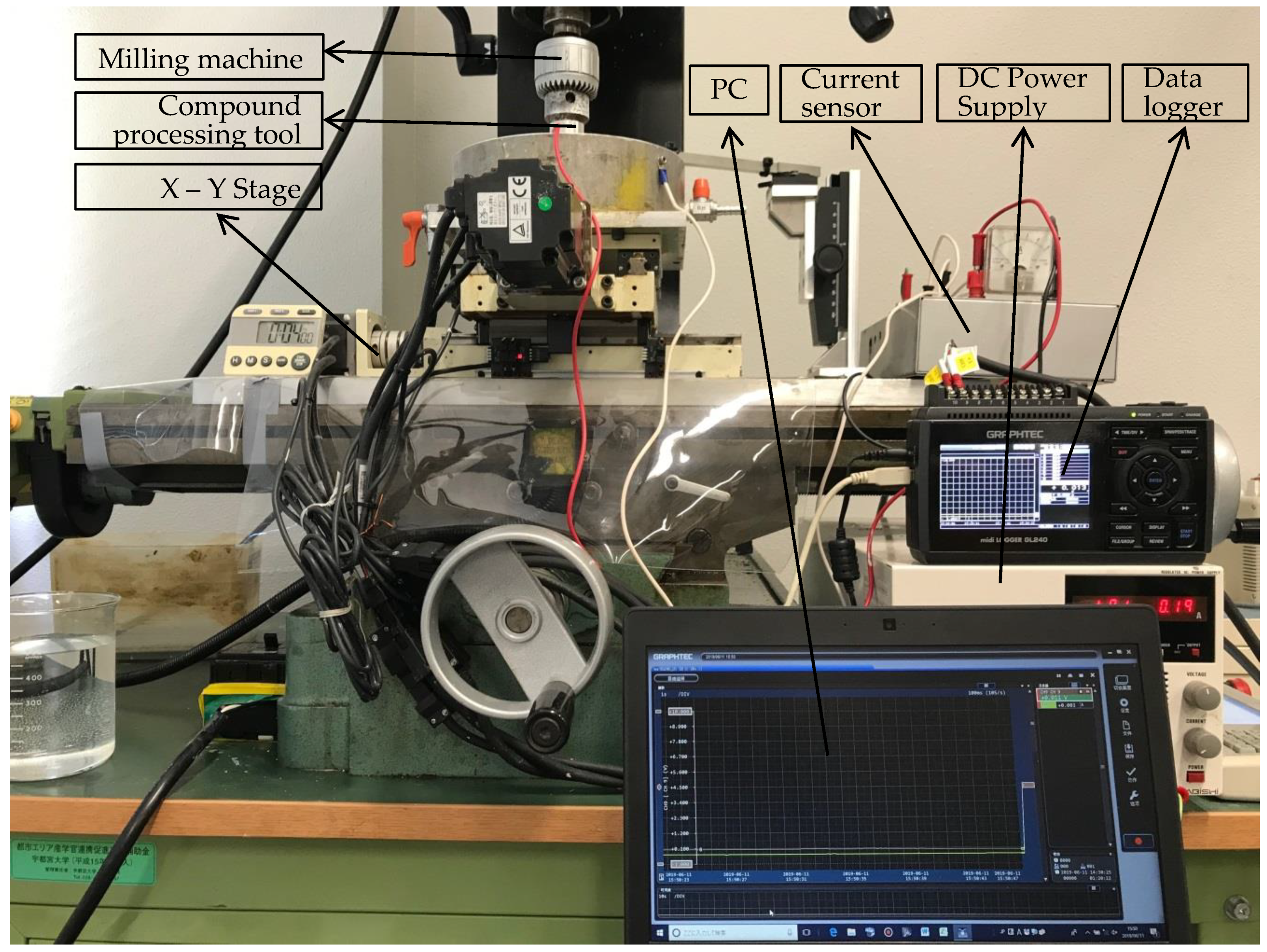
As shown in Figure 3, the EMAF experimental setup mainly includes the EMAF processing setup (vertical milling machine, X-Y stage and compound processing tool), DC power supply and the current measuring and recording setup (current sensor, data logger and PC). In the EMAF processing, the compound processing tool is clamped on the spindle of the milling machine and rotates with the spindle. The workpiece is driven by the X-Y stage to move in the horizontal direction. The electrolysis reactions in the EMAF process are powered by the DC power supply.

3.2. Current Measuring and Recording Setup

According to Formula (1), the processing current is one of the important processing parameters. The intensity of the electrolysis reaction in the EMAF process can be judged by the current value, and the current fluctuation can be used to judge whether there is a short-circuit phenomenon during EMAF processing. In this paper, the measured current curve is used to analyze the experimental results. As shown in Figure 3, the current measuring and recording set up includes a current sensor, a data logger and a computer.
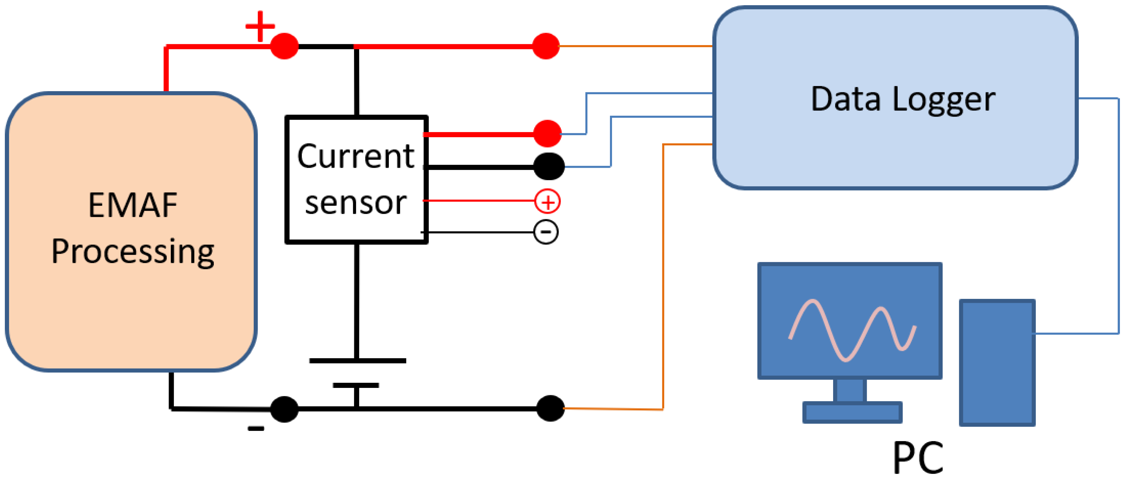
The schematic of current measuring and recording set up is shown in Figure 4. The current flowing out from the DC power supply flows through the current sensor for EMAF processing. After the processing current flows through the current sensor, the current value is converted into an output voltage of 0–10 V. The EMAF processing voltage and the current sensor output voltage are recorded by data logger. The voltage and current curves during the EMAF processing are transmitted and saved to the computer for reviewing.

3.3. Simulation of Magnetic Induction

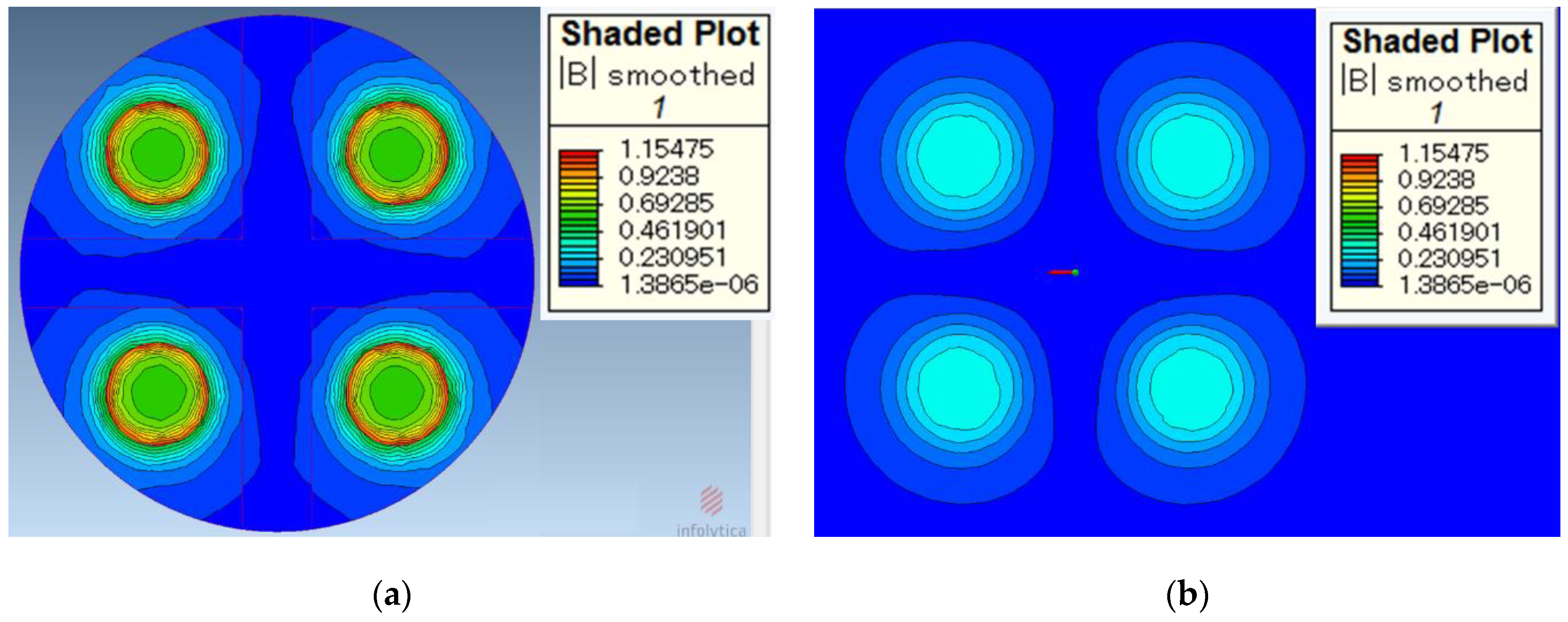
MagNet (64-bit Version 7) is used as the simulation software for this study. The simulation of the magnetic induction on the surface of the processing tool and the surface of the workpiece is shown in Figure 5, respectively. Figure 5a shows the magnetic induction on the surface of the processing tool. It can be seen from the simulation results that the magnetic induction is the largest at the edges of magnetic poles. The magnetic induction is slightly weaker on the surface of the magnetic pole and near the edge. The magnetic induction outside the magnetic pole debilitates rapidly. If the magnetic induction is too weak, the magnetic brush cannot provide sufficient finishing pressure.
Figure 5b shows the magnetic induction on the surface of the workpiece when the working gap is 1 mm. It can be seen from the simulation results that the magnetic induction on the surface of the workpiece is obviously weaker than that on the surface of the processing tool. According to Formulas (4) and (5), the finishing pressure of the magnetic brush is greater when it is closer to the processing tool.

4. Experimental Results and Discussion

The feasibility of this processing tool for EMAF processing of SUS 304 stainless steel has been proven [8], and the machining mechanism has been further studied [11]. However, the processing effect of this tool on aluminum alloy A5052 has not been explored. These experiments are used to explore the finishing effect of the compound processing tool in the neutral electrolyte (NaNO3) on aluminum alloy A5052 plate. Based on the analysis of the experimental results, the rationality of the processing tool design is further discussed. Furthermore, according to the proven machining mechanism, the future research is planned and prospected.

4.1. Experiment of Electrolysis in EMAF Process

Because of the active chemical properties of aluminum, it is necessary to explore the effect of electrolysis reactions on the aluminum alloy A5052 workpiece during EMAF process. The experimental conditions are shown in Table 1. Aluminum alloy A5052 plate is selected as the work piece, the size is 100 by 100 by 1 mm. NaNO3 aqueous solution was selected as the electrolyte with a concentration of 15%. The changes of material removal (MR) and surface roughness (SR) was investigated at the processing voltage of 4 V, 5 V and 6 V, respectively. Due to the limitation of the workpiece size and the feed speed of the X-Y stage, the one-way movement time of the X-Y stage is 12 s, and the time of each reciprocating cycle is 24 s. The EMAF processing time in this experiment is a multiple of 24 s, and the total processing time is 216 s.
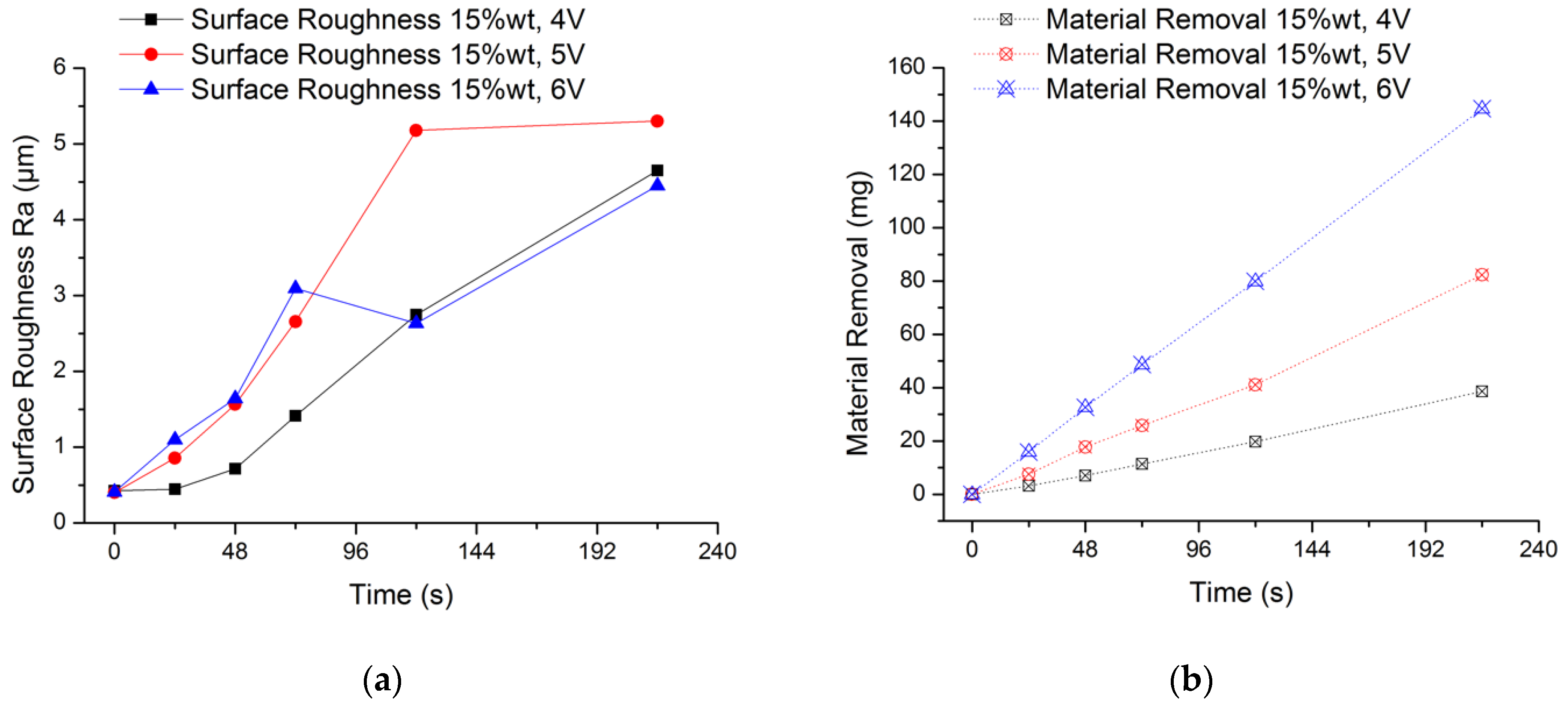
The experimental results are shown in Figure 6. It can be seen from the Figure 6a that the average surface roughness value of the workpiece surface is increasing regardless of the voltage condition. What is more, there is no obvious law for the increase of surface roughness value. This is because the passive film formed on the surface of the workpiece cannot be removed in time. Moreover, the rough surface of the initial workpiece and the irregular formation of the passive film will also make the surface of the workpiece more uneven. When the processing voltage is 6 V, the surface roughness value fluctuates greatly from 48 s to 120 s. In order to better explain this phenomenon, the analysis is carried out in conjunction with the amount of material removal in Figure 6b. When the processing voltage is 6 V, the measured surface roughness value reaches Ra 3.1 μm at 72 s, and the material removal amount is 48.7 mg; when processing to 120 s, the surface roughness value drops to 2.6 μm, and the amount of material removal is 79.9 mg. One of the reasons for the sudden change of the surface roughness value is that the passive film on the surface of the workpiece becomes uneven as the electrolysis reaction proceeds. A non-uniform passive film will result in a different intensity of electrolytic reaction on the machined surface, and when it accumulates to a certain extent, it will easily cause a sudden change in the surface roughness value. In this experiment, the removal of the passive film mainly depends on the washing of flowing electrolyte by the compound processing tool rotating and stirring the electrolyte. Therefore, the more electrolytic products accumulated during processing, the rougher the surface, the stronger the scouring effect of the electrolyte, and the easier the passive film is removed. This explains why the surface roughness value at 120 s is lower than at 72 s. It can be seen from the Figure 6b that the higher the processing voltage, the higher the material removal. Further, as time increases, the amount of material removal increases. The final material removal amount is 38.61 mg, 82.34 mg and 144.7 mg when using 4 V, 5 V and 6 V processing voltage, respectively. From the change law of material removal in this experiment, the electrolysis reaction in the EMAF process will be accelerated as the processing voltage increases.

4.2. MAF Experimental Conditions and Results

As an important part of the EMAF process, the MAF process plays a role in removing the passive film and further finishing the surface of the workpiece during the EMAF processing. If the processing capacity of MAF is not enough, the passive film will remain on the surface of the workpiece, which will affect the finished surface quality. Therefore, it is very important to select appropriate processing parameters according to different conditions during processing.
The experimental conditions are shown in Table 2. The processing time of each stage is 5 min. Electrolytic iron powders of 330 μm and 149 μm were selected as magnetic particles, and WA# 10000, WA# 20000 and WA# 30000 were selected as abrasives, respectively.
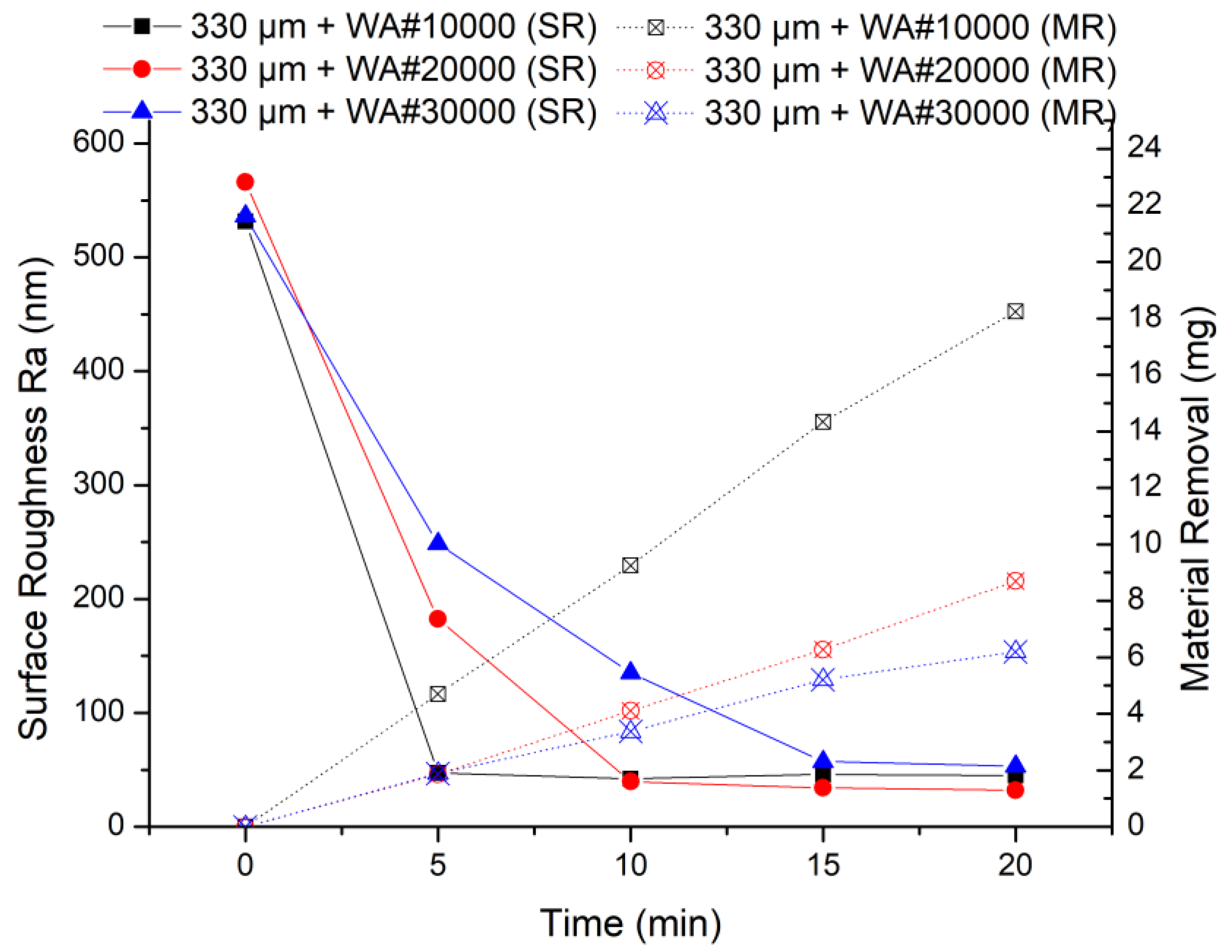
The results of the MAF experiment are shown in Figure 7, when using 330 μm electrolytic iron powder. It can be seen from the experimental results that 330 μm + WA# 10000 has the highest finishing efficiency in the early stage of processing. The smaller the abrasive particle size, the lower the processing efficiency. This is because in the same experimental conditions, the larger the abrasive grain size, the more severe the collision with the protrusions on the workpiece surface.
When 149 μm electrolytic iron powder was selected, the results of the MAF experiment are shown in Figure 8. It can be seen from the experimental results that 149 μm + WA# 10000 has the highest processing efficiency in the early stage of finishing, which is similar to when using 330 um electrolytic iron powder. However, the finishing capacity of 149 μm + WA# 20000 and 149 μm + WA# 30000 is similar, which is quite different from when using 330 um electrolytic iron powder. This is because when using 149 μm iron powder, the finishing pressure is lower, according to Formulas (4) and (5). Small finishing pressure and too small abrasive particle size result in insufficient collision between abrasive particles and the surface of the workpiece.
Comparing the two sets of experiments, the finishing efficiency is highest when 330 μm electrolytic iron powder and WA# 10000 abrasive particles are used for processing. Moreover, no matter whether electrolytic iron powder of 330 μm or 149 μm is used, the finishing efficiency of WA# 10000 is always the highest. From the experimental results of material removal, when using WA# 10000 abrasive, the material removal is much higher than the other two types of abrasives. Furthermore, when using 330 μm electrolytic iron powder, the highest material removal obtained after 20 min of processing is 18.24 mg; when using 149 μm electrolytic iron powder processing for 30 min, the highest material removal obtained is 19.41 mg. The final surface roughness values show that the finishing effect of using 149 μm electrolytic iron powder is relatively better than that of using 330 μm electrolytic iron powder.

4.3. Experiment of EMAF Processing

Through the previous experiments, the processing characteristics of electrolysis reactions in the EMAF process and the MAF processing characteristics of the processing tool have been initially explored. From the previous experimental results, the material removal by electrolysis reactions in the EMAF process is significantly higher than that in the MAF process. However, if only the electrolytic reactions in the EMAF process are used for processing by using this compound processing tool, the passive film will remain on the surface, resulting in uneven surface.
In order to obtain a better composite processing effect, 330 μm electrolytic iron powder with higher finishing efficiency will be used during EMAF processing (Stage 1). After the first stage of processing, 149 μm electrolytic iron powder will be used to continue finishing the workpiece for 5 min (Stage 2). Because the WA# 10000 abrasive has the highest processing efficiency in previous experiments, WA# 10000 abrasive is used for the next experiment. The processing voltage is initially set at 4 V, so the passive film can be removed more effectively. The EMAF experimental conditions are shown in Table 3.
The experimental results of EMAF processing are shown in Figure 9. From the results of the EMAF experiment, it can be seen that the material removal of EMAF processing in 2 min is 4.9 mg, which is greater than the maximum material removal of 4.7 mg by 5 min MAF processing. It can also be seen that the finishing efficiency is greatly improved when using the EMAF process to finish the aluminum alloy A5052, compared with the traditional MAF process. After the first stage of finishing, the total material removal is 8.85 mg; after the second stage of finishing, the final material removal is 12.75 mg.
But from the change of surface roughness, the average surface roughness after EMAF processing is about Ra 175 nm. After the first stage of finishing, it reaches about Ra 86 nm, and after the second stage of finishing, it finally reaches Ra 56 nm. Since the surface roughness value does not reach below Ra 50 nm, it is necessary to further explore more suitable processing parameters. Through microscope observation, it is found that after the EMAF processing, some electrolytic reaction products still remain on the processed surface that have not been completely removed.
The observed surfaces by microscope after finishing are shown in Figure 10. It can be seen from the figure that after EMAF processing, the surface of the workpiece is not uniform, and there are still some electrolysis reaction products that cannot be removed in time. However, after the MAF process in the first stage, the electrolysis reaction products remain on surface are basically removed. After the second stage of MAF processing, the surface becomes smoother.

4.4. Further Study on the EMAF Processing Parameters

In order to obtain a better finishing effect, the processing parameters have been optimized in this section. Through the previous experiments and figures, it can be concluded that there are still electrolysis reaction products on the surface of the workpiece after EMAF processing, and the electrolysis reaction speed in EMAF increases with the increase of processing voltage. Therefore, for the purpose of improving the finished surface quality, priority is given to reducing the processing voltage to reduce the electrolysis reaction speed in the EMAF process. The new EMAF processing conditions are shown in Table 4.
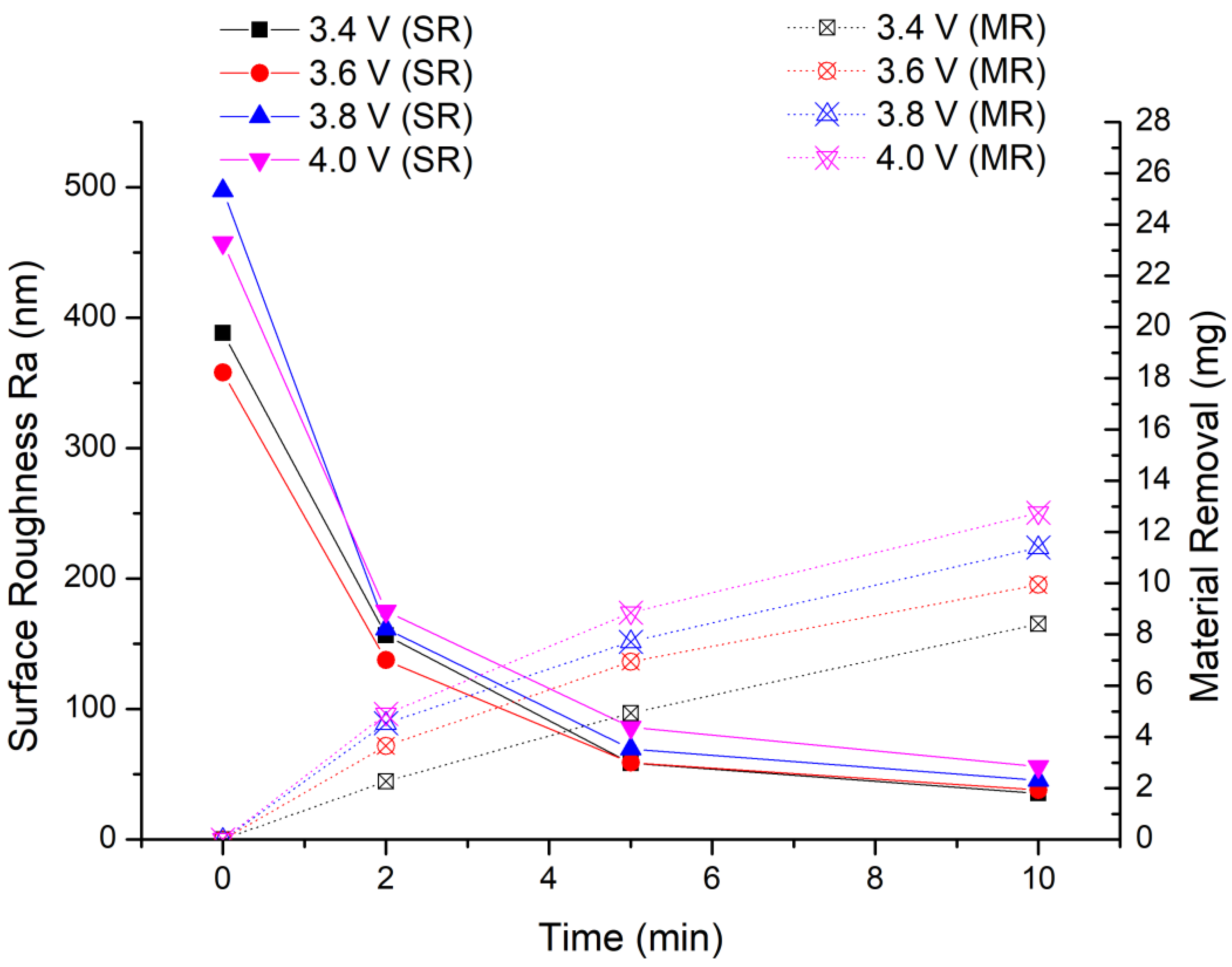
In this experiment, we keep the other experimental conditions unchanged and only lower the processing voltage. The experimental results are shown in Figure 11. It can be seen from the experimental results that the amount of material removal decreases as the processing voltage decreases. After the first stage of processing, the material removal is 4.93 mg, 6.94 mg and 7.72 mg when the processing voltage is 3.4 V, 3.6 V and 3.8 V, respectively. The lowest material removal is 4.93 mg at 3.4 V, but it is still greater than the maximum material removal (4.7 mg) of 5 min MAF processing in the previous experiment. After two stages of finishing, the material removal is 8.41 mg, 9.94 mg and 11.4 mg when the processing voltage is 3.4 V, 3.6 V and 3.8 V, respectively. The amount of material removal at each stage shows the rule that the greater the processing voltage, the larger amount of material removal.
From the final average surface roughness value, the optimal surface roughness of the workpiece is Ra 35.5 nm at 3.4 V. The surface roughness values at other processing voltages are Ra 38 nm at 3.6 V and Ra 45.5 nm at 3.8 V. Therefore, when the finishing voltage is 3.4 V, the finished surface with the lowest surface roughness value is obtained.

4.5. Discussion of Processing Current and 3D Topography

4.5.1. EMAF Processing Current

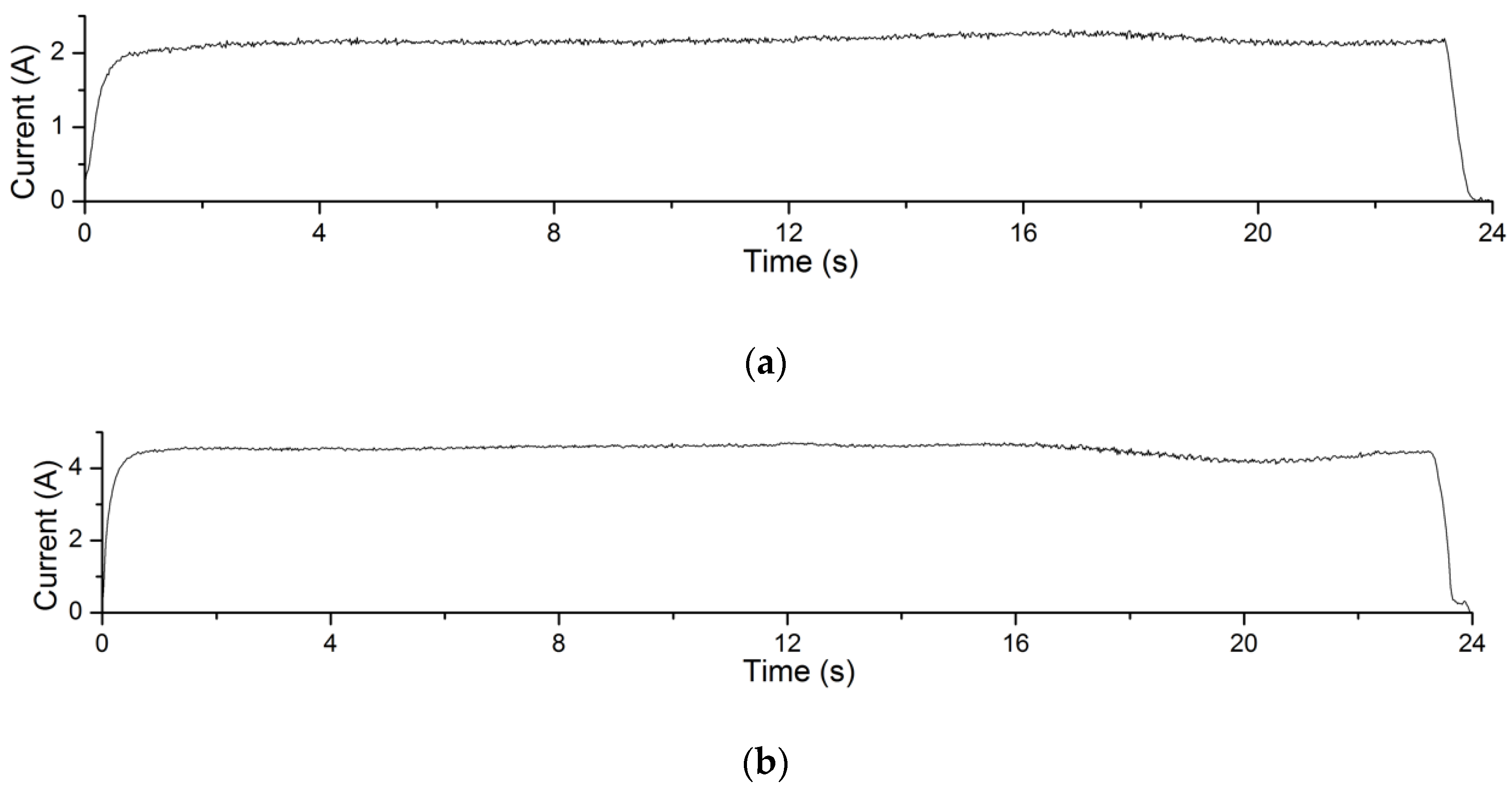
The electrolysis reaction current curves in Experiment 4.1 are shown in Figure 12. The processing voltage values corresponding to the current curves in Figure 12a–c are 4 V, 5 V and 6 V, respectively. The recording time of the processing current is 24 s. It can be seen from the figures that in this experiment, the greater the processing voltage, the greater the processing current. According to Formula (1), under the same processing conditions, the greater the processing current, the greater the amount of material removal achieved. This explains the changing trend of material removal of Experiment 4.1.
The current curves during EMAF processing of the Experiment 4.4 are shown in Figure 13. The processing voltage values corresponding to the current curves in Figure 13a–d are 3.4 V, 3.6 V, 3.8 V and 4.0 V, respectively. It can be seen that the processing current of the EMAF process also increases with the increase of the processing voltage. Similarly, according to Formula (1), the greater the processing current during the EMAF processing, the greater the amount of material removal achieved.

4.5.2. 3D Topography of Finished Surfaces

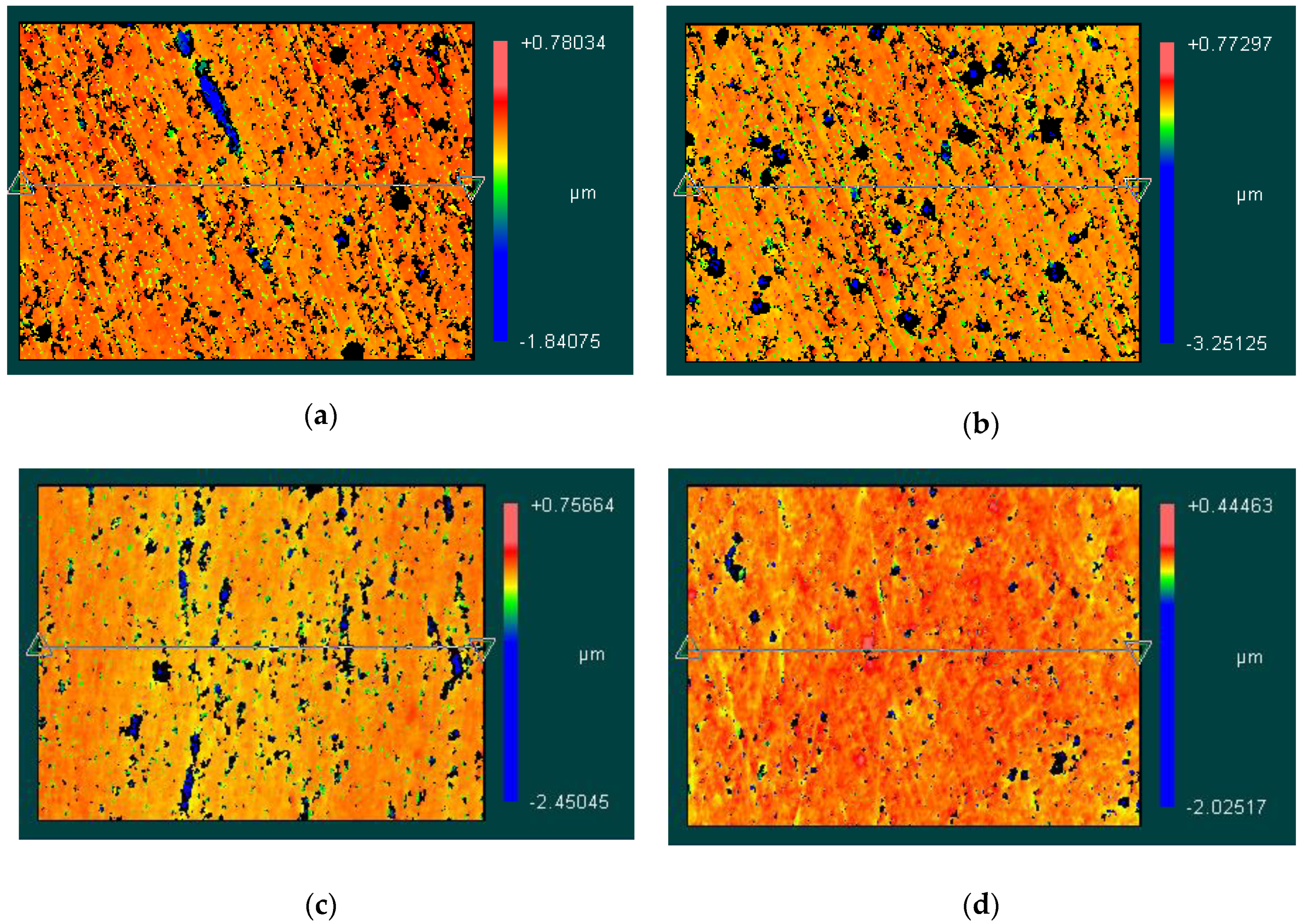
The 3D topography measured by Zygo NewView7300 are shown in Figure 14. Figure 14a–d correspond to the EMAF processing voltage values of 4.0 V, 3.8 V, 3.6 V and 3.4 V, respectively. It can be seen from the figures that when the processing voltage decreases, the surface of the workpiece gradually becomes uniform. However, due to the strong metal activity of aluminum alloy itself, it is relatively difficult to control the intensity of electrolysis reactions. Therefore, surface defects are prone to appear on the finished surface after EMAF processing.

5. Discussion

The experimental results have proved the feasibility of using the compound processing tool for EMAF process to finish aluminum alloy A5052. Additionally, the processing efficiency of the EMAF process shows better results than that of the traditional MAF process. It can be seen from Figure 5 that the magnetic induction at the edge of compound processing tool is weak. So according to Formulas (4) and (5), the finishing pressure at the edge of the processing tool is slightly insufficient. It is not obvious when processing SUS304 stainless steel [8,11]. However, due to the higher metal activity of aluminum, there will be more passive films left on the edges during the EMAF processing.

6. Conclusions

After a series of experiments to explore the feasibility of the compound processing tool for finishing aluminum alloy A5052 by EMAF process, the conclusions are as follows:
  • Through a series of experiments, it is proved that the compound processing tool with arrangement of a cross electrode and four magnetic poles in the same direction can finish aluminum alloy A5052 by EMAF process.
  • Compared with the traditional MAF process, when finishing the surface of aluminum alloy A5052 by the same compound processing tool and at the same experimental conditions (except the electrolysis conditions), the EMAF process, which includes electrolysis reactions, can achieve higher finishing efficiency.
  • The processing current of the EMAF process increases with the increase of the processing voltage within a certain range.
  • When using EMAF process to finish the surface of aluminum alloy A5052, the processing voltage should not be too high. In this experiment, when the working gap is 1 mm and the concentration of NaNO3 aqueous solution is 15%, the recommended processing voltage is about 3.4 V.

Author Contributions

Project administration, Y.Z.; experiments B.X. and Y.Z.; data curation, B.X. and Y.Z.; writing—original draft preparation, B.X. and Y.Z.; writing—review and editing, B.X. and Y.Z.; Simulation, B.X. All authors have read and agreed to the published version of the manuscript.

Funding

This research received no external funding.

Conflicts of Interest

The authors declare no conflict of interest.

References

  1. Shinmura, T.; Takazawa, K.; Hatano, E.; Aizawa, T. Study on magnetic abrasive process -process principle and finishing possibility. Bull. JSPE 1985, 19, 54. [Google Scholar]
  2. Shinmura, T.; Takazawa, K.; Hatano, E.; Matsunaga, M. Study on magnetic abrasive finishing. CIRP Ann. Manuf. Technol. 1990, 39, 325–328. [Google Scholar] [CrossRef]
  3. Singh, D.K.; Jain, V.; Raghuram, V. Experimental investigations into forces acting during a magnetic abrasive finishing process. Int. J. Adv. Manuf. Technol. 2006, 30, 652–662. [Google Scholar] [CrossRef]
  4. Kim, J.D.; Choi, M.S. Simulation for the prediction of surface-accuracy in magnetic abrasive machining. J. Mater. Process. Technol. 1995, l53, 630–642. [Google Scholar] [CrossRef]
  5. Yamaguchi, H.; Shinmura, T.; Kaneko, T. Development of a new internal finishing process applying magnetic abrasive finishing by use of pole rotation system. Int. J. Japan Soc. Prec. Eng. 1996, 30, 317. [Google Scholar]
  6. Jain, V.K. Magnetic field assisted abrasive based micro-/nano-finishing. J. Mater. Process. Technol. 2009, 209, 6022–6038. [Google Scholar] [CrossRef]
  7. Zou, Y.; Shinmura, T. Study on magnetic field-assisted machining process for internal finishing using magnetic machining jig. Key Eng. Mater. 2004, 257, 505–510. [Google Scholar] [CrossRef]
  8. Sun, X.; Zou, Y. Development of magnetic abrasive finishing combined with electrolytic process for finishing SUS304 stainless steel plane. Int. J. Adv. Manuf. Technol. 2017, 92, 3373–3384. [Google Scholar] [CrossRef]
  9. McGeough, J.A. Principles of Electrochemical Machining; Chapman and Hall: London, UK, 1974. [Google Scholar]
  10. McGeough, J.A.; Barker, M.B. Electrochemical machining. Int. J. Chemtech. Res. 1991, 9, 536–542. [Google Scholar]
  11. Zou, Y.; Xing, B.; Sun, X. Study on the magnetic abrasive finishing combined with electrolytic process—Investigation of machining mechanism. Int. J. Adv. Manuf. Technol. 2020, 108, 1675–1689. [Google Scholar] [CrossRef]
  12. Rajurkar, K.P.; Zhu, D.; Mcgeough, J.A. New Development in electro-chemical machining. CIRP Ann. Manuf. Technol. 1999, 48, 567–579. [Google Scholar] [CrossRef]
  13. Labib, A.W.; Keasberry, V.J.; Atkinson, J.; Frost, H.W. Towards next generation electrochemical controllers: A fuzzy logic control approach to ECM. Expert Syst. Appl. 2011, 38, 7486–7493. [Google Scholar] [CrossRef]
  14. Rajesh Jesudoss Hynes, N.; Kumar, R. Electrochemical Machining of Aluminium Metal Matrix Composites. Surf. Eng. Appl. Electrochem. 2018, 54, 367–373. [Google Scholar] [CrossRef]
  15. Abhijeet, B.; Dilip, M. A Comprehensive Study of an Aluminum Alloy AL-5052. Appl. Phys. Lett. 2016, 3, 20–22. [Google Scholar]
  16. Aluminium Alloy Data Sheet 5052 of Atlas Steels. Available online: http://www.atlassteels.com.au/documents/Atlas_Aluminium_datasheet_5052_rev_Oct_2013.pdf (accessed on 6 November 2020).
  17. Rebecca, J.L.; Atanas, I. Electrochemical micromachining: An introduction. Adv. Mech. Eng. 2016, 8, 1–13. [Google Scholar]
  18. Natsu, W.; Kunimi, T. Analysis of ECM phenomena with equivalent circuit for electrolysis. Int. J. Electr. Mach. LJEM 2009, 15, 45–50. [Google Scholar]
  19. Natsu, W. Basic Theory and Actual Situation of Electrochemical Machining. J. Jpn. Soc. Prec. Eng. 2015, 81, 317–322. [Google Scholar] [CrossRef]
  20. Natsume, M.; Shinmura, T. Study on the mechanism of plane magnetic abrasive finishing process-elucidation of normal force characteristics. Trans. Jpn. Soc. Mech. Eng. 2008, 74, 212–218. [Google Scholar] [CrossRef] [Green Version]
  21. Shinmura, T.; Takazawa, K.; Hatano, E.; Aizawa, T. Study on magnetic abrasive process-finishing characteristics. Bull. JSPE 1984, 18, 347. [Google Scholar]
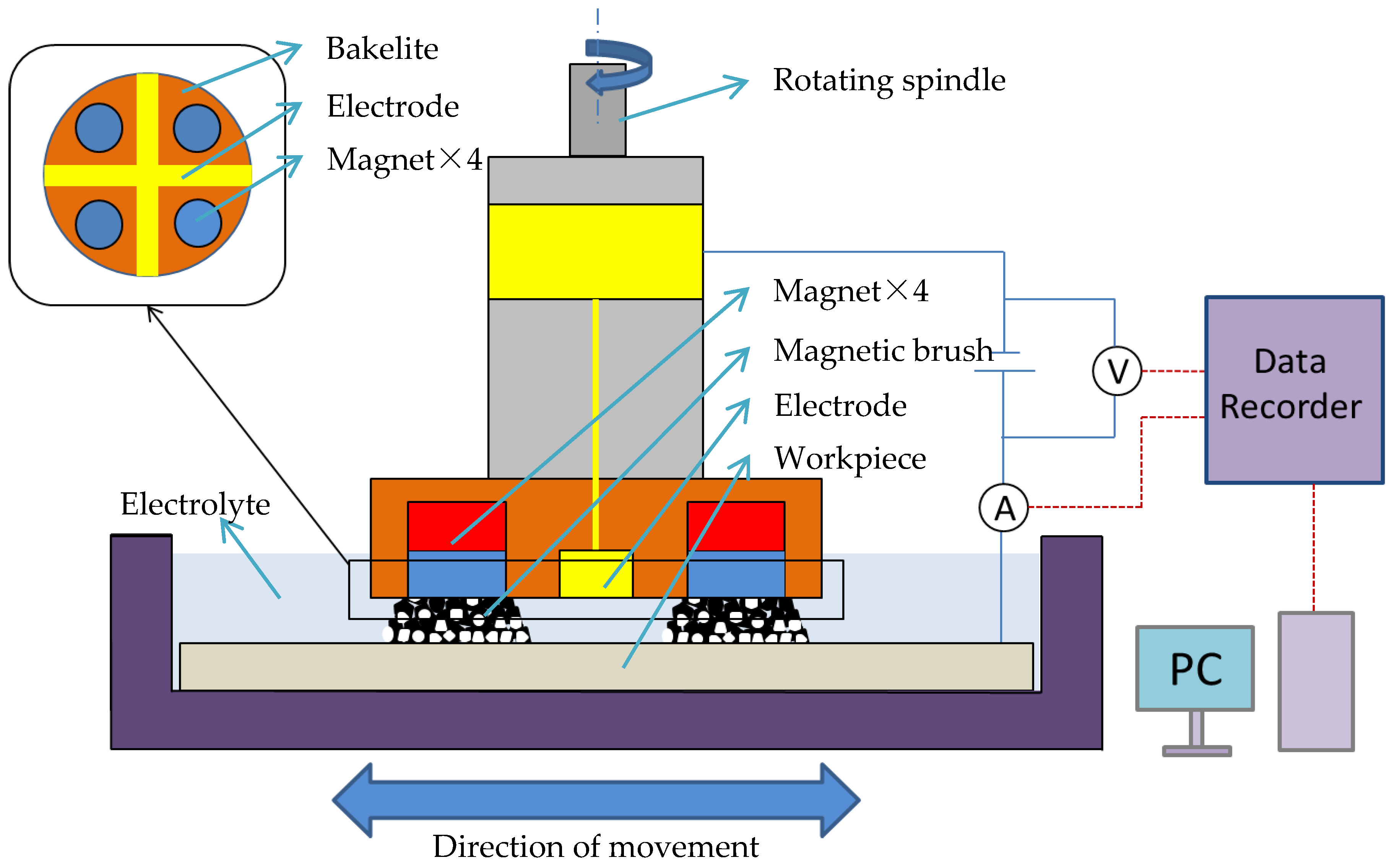
Figure 1. Schematic of magnetic abrasive finishing combined with electrolytic process (EMAF) processing principle.
Machines 08 00078 g001
Figure 2. Schematic of electrolysis reactions during the EMAF process.
Machines 08 00078 g002
Figure 3. External view of experimental setup.
Machines 08 00078 g003
Figure 4. Schematic of current measuring and recording set up.
Machines 08 00078 g004
Figure 5. Simulation of magnetic induction. (a) magnetic induction on the surface of processing tools and (b) magnetic induction on the surface of the workpiece (working gap 1 mm).
Machines 08 00078 g005
Figure 6. Experimental results of electrolysis in EMAF process. (a) Changes of surface roughness during processing and (b) changes of material removal during processing.
Machines 08 00078 g006
Figure 7. MAF process experimental results (330 μm electrolytic iron powder).
Machines 08 00078 g007
Figure 8. MAF process experimental results (149 μm electrolytic iron powder).
Machines 08 00078 g008
Figure 9. EMAF process experimental results.
Machines 08 00078 g009
Figure 10. Observed surface by microscope after finishing. (a) Finished surface after EMAF processing; (b) finished surface after Stage 1; and (c) finished surface after Stage 2.
Machines 08 00078 g010
Figure 11. Optimization experiment of EMAF processing parameters.
Machines 08 00078 g011
Figure 12. Processing current curves of electrolysis reactions in EMAF process. (a) The current curve when processing voltage is 4 V; (b) the current curve when processing voltage is 5 V; and (c) the current curve when processing voltage is 6 V.
Machines 08 00078 g012aMachines 08 00078 g012b
Figure 13. Processing current curves of EMAF process. (a) the current curve when processing voltage is 3.4 V; (b) the current curve when processing voltage is 3.6 V; (c) the current curve when processing voltage is 3.8 V; and (d) the current curve when processing voltage is 4.0 V.
Machines 08 00078 g013
Figure 14. 3D topography of finished surfaces. (a) the 3D topography when processing voltage is 4.0 V; (b) the 3D topography when processing voltage is 3.8 V; (c) the 3D topography when processing voltage is 3.6 V; and (d) the 3D topography when processing voltage is 3.4 V.
Machines 08 00078 g014
Table 1. Experimental conditions of electrolysis in EMAF process.
ItemExperimental Conditions
WorkpieceAluminum alloy A5052 plane (100 × 100 × 1 mm)
ElectrolyteNaNO3 15% wt
Processing voltage4 V, 5 V, 6 V
Working gap1 mm
Stage feed speed5 mm/s
Tool rotation speed450 rpm
Total processing time216 s
Table 2. Experimental conditions of magnetic abrasive finishing (MAF) process.
ItemExperimental Conditions
WorkpieceAluminum alloy A5052 plane (100 × 100 × 1 mm)
Electrolytic iron powders330 μm, 149 μm
Abrasives particlesWA# 10000, WA# 20000, WA# 30000
Working gap1 mm
Stage feed speed5 mm/s
Tool rotation speed450 rpm
Processing time5 min/stage
Table 3. EMAF experimental conditions.
ItemExperimental Conditions
WorkpieceAluminum alloy A5052 plane (100 × 100 × 1 mm)
Electrolytic iron powders330 μm (Stage 1), 149 μm (Stage 2)
Abrasives particlesWA# 10000
ElectrolyteNaNO3 15% wt
Processing voltage4 V
Working gap1 mm
Stage feed speed5 mm/s
Tool rotation speed450 rpm
Processing time (Stage 1)EMAF (2 min) + MAF (3 min)
Processing time (Stage 2)MAF (5 min)
Table 4. EMAF experimental conditions for optimization of processing parameters.
ItemExperimental Conditions
WorkpieceAluminum alloy A5052 plane (100 × 100 × 1 mm)
Electrolytic iron powders330 μm (Stage 1), 149 μm (Stage 2)
Abrasives particlesWA# 10000
ElectrolyteNaNO3 15% wt
Processing voltage4 V, 3.8 V, 3.6 V, 3.4 V
Working gap1 mm
Stage feed speed5 mm/s
Tool rotation speed450 rpm
Processing time (Stage 1)EMAF (2 min) + MAF (3 min)
Processing time (Stage 2)MAF (5 min)
Publisher’s Note: MDPI stays neutral with regard to jurisdictional claims in published maps and institutional affiliations.