Strategy for Application of Support Object for Fall Prevention in the Elderly Based on Balance Recovery Characteristics

Abstract
1. Introduction
- I.
- Partial weight bearing of legs
- II.
- Obtaining kinematic information of whole body
2. Modeling Reaction Force Characteristics of Support Objects
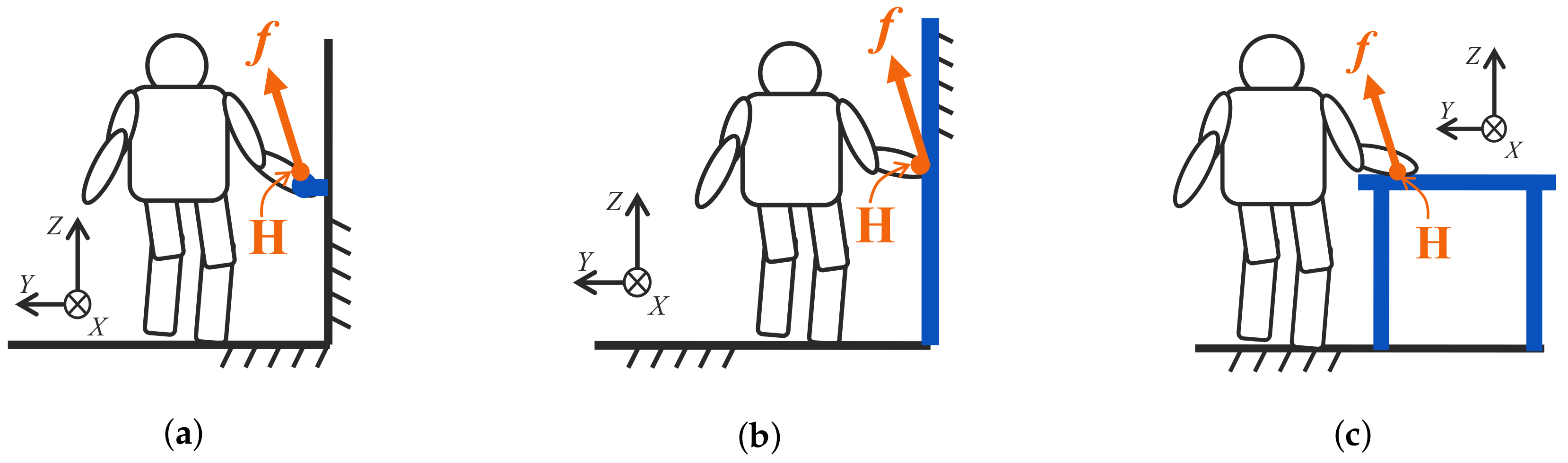
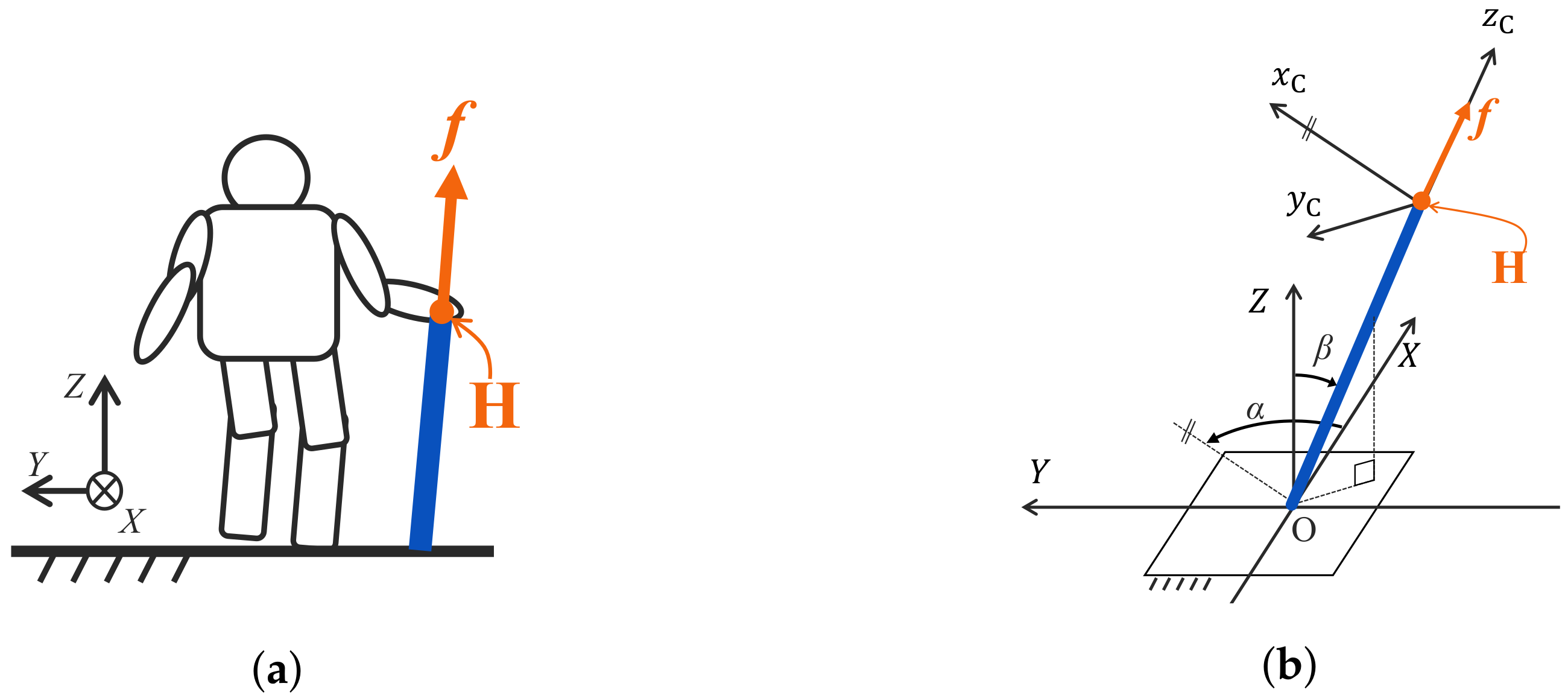
2.1. Support Objects in This Paper
2.2. Modeling Reaction Force Characteristics
3. Assessment Method of Support Object Based on Balance Recovery Characteristics
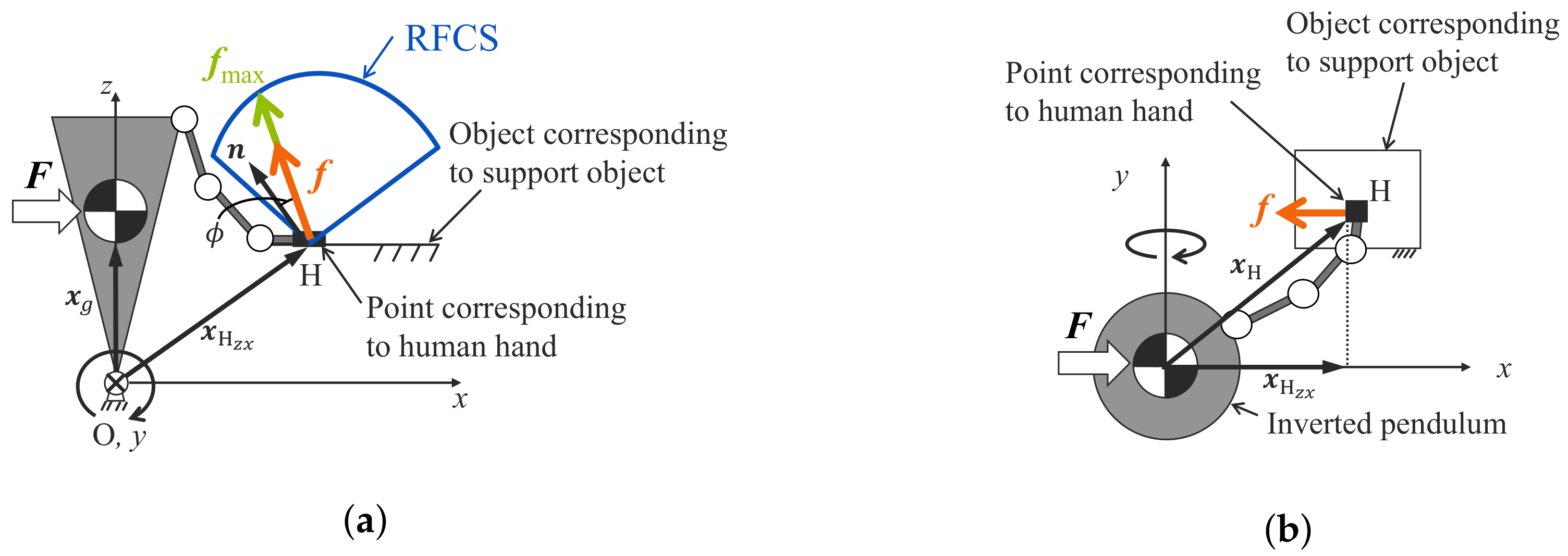
3.1. Reaction Force Characteristic Solid (RFCS)
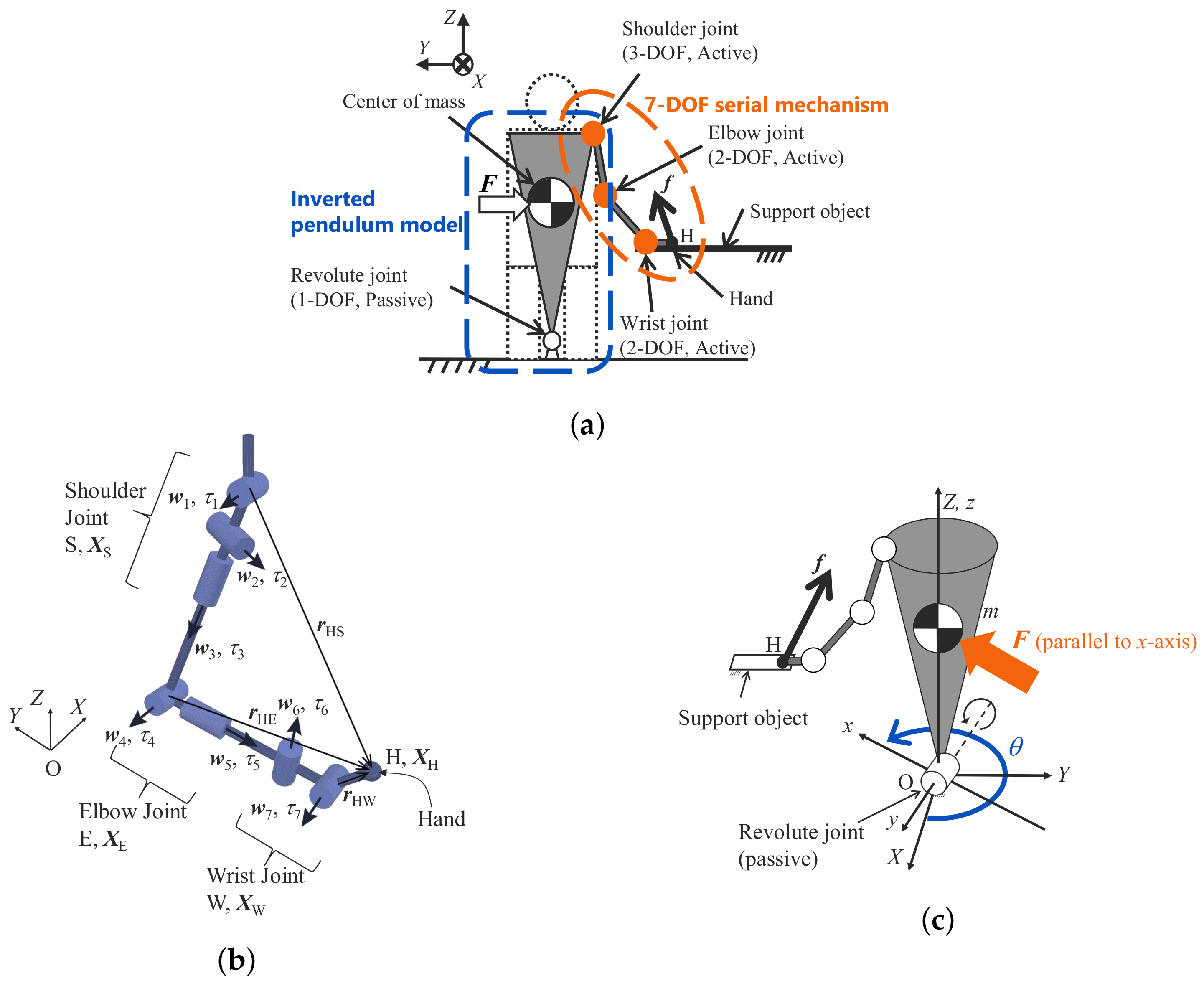
3.1.1. Analysis Model
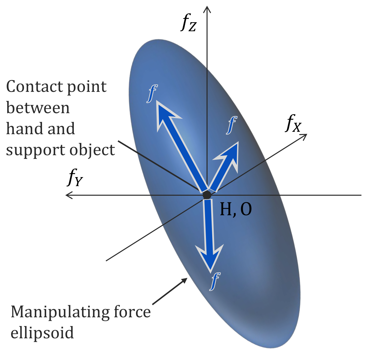
3.1.2. Manipulating Force Ellipsoid
3.1.3. Reaction Force Characteristic Solid (RFCS)
3.2. Evaluation Index Regarding Balance Recovery Characteristics Based on RFCS
- Based on the RFCS, the reaction force effective for balance recovery is derived.
- The reaction force whose direction is the same as and whose magnitude is necessary for balance recovery is derived.
- The margin S, which is the ratio of the magnitude of to the magnitude of , is derived.
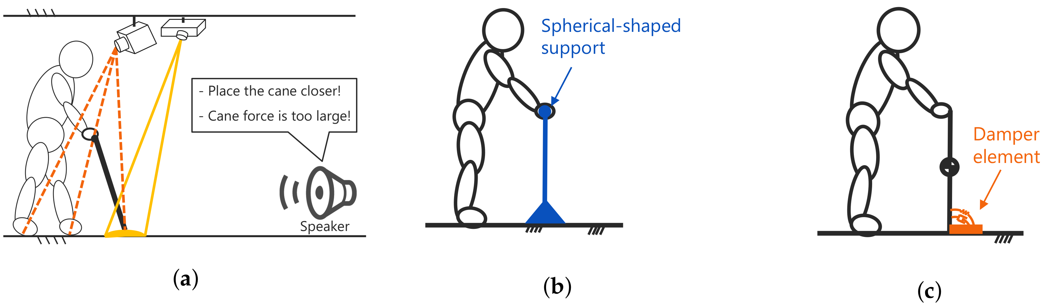
4. Assessment Method of Anterior Position of Cane Tip Based on Model with Dynamic Pair
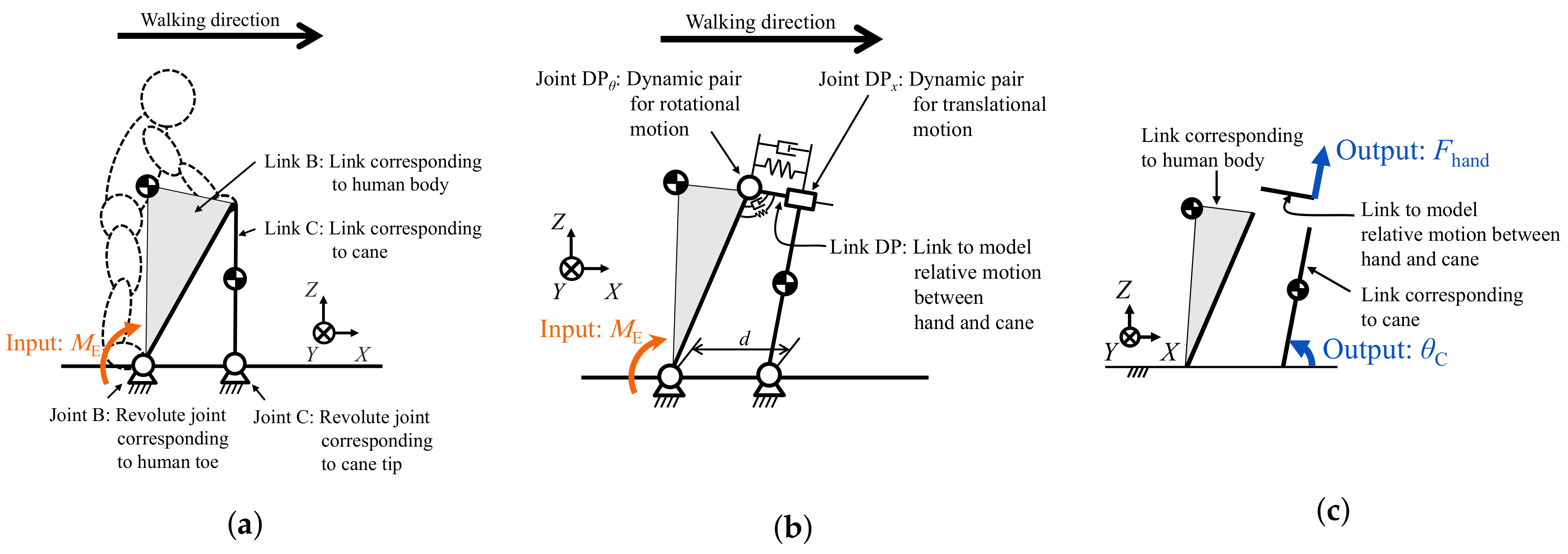
4.1. Dynamic Analysis Using Model with Dynamic Pair
4.1.1. Analysis Model Used in the Simulation
- i.
- Movable direction: translational and rotational directions.
- ii.
- Viscoelastic characteristics: linear elastic and damping effects in each movable direction.
4.1.2. Simulation Result
4.2. Evaluation Indices for Anterior Position of Cane Tip
4.2.1. Amount of Energy Dissipation by Damper Element of Dynamic Pair
4.2.2. Magnitude of Force Acting on Hand from Cane
4.2.3. Ability to Perform Negative Work at Each Joint
4.3. Method for Determination of Cane Tip Position Useful for Preventing Anterior Fall
5. Proposal of Strategy for Application of Support Objects
5.1. Assessment Example for a Single Support Object
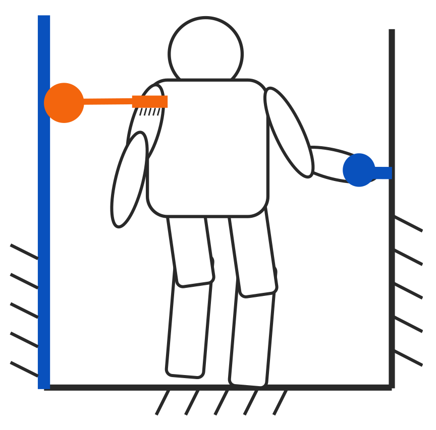
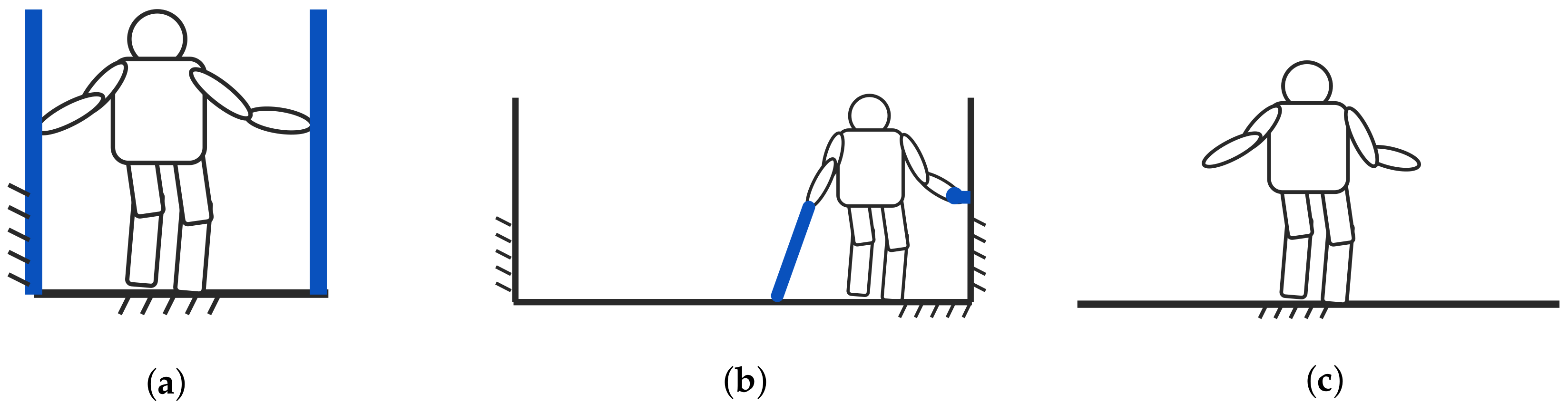
5.1.1. Prerequisites
- Case 1.
- Walking with a handrail
- Case 2.
- Walking while touching the top of a table
- Case 3.
- Walking while pinching the edge of a table by his/her hand
- Case 4.
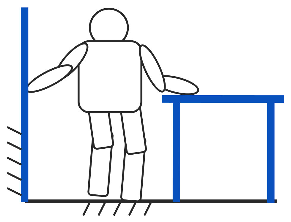
- Walking while touching a wall
- Case 5.
- Walking while touching a wall that has low friction
- Case 6.
- Walking with a cane
5.1.2. Assessment Results and Discussion
- A.
- There are many directions in which the reaction force can be obtained.
- B.
- There is a sufficient margin for the magnitude of force to recover balance.
- Priority 1.
- Walk while touching the handrail.
- Priority 2.
- If there are no handrails around and there is a table or wall, walk while touching it.
- Priority 3.
- Carry a cane always, and if there is nothing around, use it to walk.
5.2. Application of Support Objects According to Physical Characteristics and Environmental Conditions
5.2.1. Setting of Physical Characteristics and Environmental Conditions
- Condition 1.
- Physical characteristics: both arms are healthy/One arm is healthy
- Condition 2.
- Physical characteristics: walking ability
- Condition 3.
- Environmental conditions: environment in which support objects are used
5.2.2. Discussion under Each Condition
Condition 1. Physical Characteristics: Both Arms Are Healthy/One Arm Is Healthy
Condition 2. Physical Characteristics: Walking Ability
Condition 3. Environmental Conditions: Environment in Which Support Objects Are Used
6. Conclusions and Future Work
Author Contributions
Funding
Acknowledgments
Conflicts of Interest
References
- Cabinet Office. Annual Report on the Ageing Society FY 2019; Cabinet Office: Tokyo, Japan, 2019. [Google Scholar]
- Raj, A.K.; Neuhaus, P.D.; Moucheboeuf, A.M.; Noorden, J.H.; Lecoutre, D.V. Mina: A sensorimotor robotic orthosis for mobility assistance. J. Rob. 2011, 2011. [Google Scholar] [CrossRef]
- Farris, R.J.; Quintero, H.A.; Goldfarb, M. Preliminary evaluation of a powered lower limb orthosis to aid walking in paraplegic individuals. IEEE Trans. Neural Syst. Rehabil. Eng. 2011, 19, 652–659. [Google Scholar] [CrossRef] [PubMed]
- Hayashi, T.; Kawamoto, H.; Sankai, Y. Control method of robot suit HAL working as operator’s muscle using biological and dynamical information. In Proceedings of the 2005 IEEE/RSJ International Conference on Intelligent Robots and Systems, Edmonton, AB, Canada, 2–6 August 2005; pp. 3063–3068. [Google Scholar]
- Boonsinsukh, R.; Panichareon, L.; Phansuwan-Pujito, P. Light touch cue through a cane improves pelvic stability during walking in stroke. Arch. Phys. Med. Rehab. 2009, 90, 919–926. [Google Scholar] [CrossRef] [PubMed]
- IJmker, T.; Lamoth, C.; Houdijk, H.; Tolsma, M.; Van Der Woude, L.; Daffertshofer, A.; Beek, P. Effects of handrail hold and light touch on energetics, step parameters, and neuromuscular activity during walking after stroke. J. Neuroeng. Rehabil. 2015, 12, 70. [Google Scholar] [CrossRef] [PubMed]
- Stramel, D.M.; Carrera, R.M.; Rahok, S.A.; Stein, J.; Agrawal, S.K. Effects of a Person-Following Light-Touch Device During Overground Walking With Visual Perturbations in a Virtual Reality Environment. IEEE Robot. Autom. Let. 2019, 4, 4139–4146. [Google Scholar] [CrossRef]
- Matsuda, S.; Matsuura, D.; Sugahara, Y.; Takeda, Y. Assessment of living space for assisting stable walks by elderly people based on evaluation of balance recovery capability (Indices for evaluation for stable walk by a single support object). Trans. JSME 2017, 83, 17-00282. (In Japanese) [Google Scholar] [CrossRef][Green Version]
- Matsuda, S.; Takeda, Y. Proposal of method for assessment of anterior position of cane tip for fall prevention during walking by elderly people based on model with dynamic pair. Trans. JSME 2020, 86, 20-00063. (In Japanese) [Google Scholar] [CrossRef]
- Di, P.; Hasegawa, Y.; Nakagawa, S.; Sekiyama, K.; Fukuda, T.; Huang, J.; Huang, Q. Fall detection and prevention control using walking-aid cane robot. IEEE/ASME Trans. Mechatron. 2015, 21, 625–637. (In Japanese) [Google Scholar] [CrossRef]
- Nakamura, Y.; Nagai, K.; Yoshikawa, T. Mechanics of Coordinative Manipulation by Multiple Robotic Mechanisms. J. Rob. Soc. Jpn. 1986, 4, 489–498. (In Japanese) [Google Scholar] [CrossRef]
- Yoshikawa, T. Foundations of Robotics: Analysis and Control; The MIT Press: Cambridge, MA, USA, 1990. [Google Scholar]
- Consumer Product Safety Association. SG Standard for Walking Sticks. 2020. Available online: https://www.sg-mark.org/SG/0073 (accessed on 20 July 2020). (In Japanese).
- Okada, H.; Ae, M.; Fujii, N.; Morioka, Y. Body Segment Inertia Properties of Japanese Elderly. Biomechanisms 1996, 13, 125–139. (In Japanese) [Google Scholar] [CrossRef]


| No. | Portability | Support Object | Shape | Reaction Force Characteristics | |
|---|---|---|---|---|---|
| Normal Force | Friction Force | ||||
| 1 | Nonportable | Handrail | Cylindrical shape | Radial direction | Longitudinal direction |
| 2 | Wall | Vertical-planar shape | Direction normal to surface | Surface direction | |
| 3 | Table | Horizontal-planar shape | Same as above | Same as above | |
| 4 | Portable | Cane | Line-segment shape | Longitudinal direction | |
| Parameter | Value |
|---|---|
| Age [year] | 75 |
| Height [m] | 1.58 |
| Mass [kg] | 57.1 |
| Walking Case | Type/Usage of Support Objects | Model of Support Objects | Index Value |
|---|---|---|---|
| 1 | Handrail | Cylindrical shape | 101 |
| 2 | Table | Horizontal-planar shape | 45 |
| 3 | Table (pinched) | Horizontal-planar shape (reaction force can be | |
| obtained in upper and lower directions) | 59 | ||
| 4 | Wall | Vertical-planar shape | 51 |
| 5 | Wall (low friction) | Vertical-planar shape | 27 |
| 6 | Cane | Line-segment shape | 12 |
© 2020 by the authors. Licensee MDPI, Basel, Switzerland. This article is an open access article distributed under the terms and conditions of the Creative Commons Attribution (CC BY) license (http://creativecommons.org/licenses/by/4.0/).
Share and Cite
Matsuda, S.; Takeda, Y. Strategy for Application of Support Object for Fall Prevention in the Elderly Based on Balance Recovery Characteristics. Machines 2020, 8, 60. https://doi.org/10.3390/machines8040060
Matsuda S, Takeda Y. Strategy for Application of Support Object for Fall Prevention in the Elderly Based on Balance Recovery Characteristics. Machines. 2020; 8(4):60. https://doi.org/10.3390/machines8040060
Chicago/Turabian StyleMatsuda, Soichiro, and Yukio Takeda. 2020. "Strategy for Application of Support Object for Fall Prevention in the Elderly Based on Balance Recovery Characteristics" Machines 8, no. 4: 60. https://doi.org/10.3390/machines8040060
APA StyleMatsuda, S., & Takeda, Y. (2020). Strategy for Application of Support Object for Fall Prevention in the Elderly Based on Balance Recovery Characteristics. Machines, 8(4), 60. https://doi.org/10.3390/machines8040060